


IntelliFlo® Variable Speed
Programmable Pump
(Compatible with IntelliComm® communication center and EasyTouch®, IntelliTouch® and SunTouch® control systems)
Installation and
User’s Guide
IMPORTANT SAFETY INSTRUCTIONS
READ AND FOLLOW ALL INSTRUCTIONS
SAVE THESE INSTRUCTIONS

i
Customer Service / Technical Support
If you have questions about ordering Pentair Water Pool and Spa (“Pentair”) replacement parts, and pool products, please use the following contact information:
Customer Service (8 A.M. to 5 P.M. — Eastern and Pacific Times)
Phone: (800) 831-7133 Fax: (800) 284-4151
Web site
visit www.pentairpool.com or www.staritepool.com to find information about Pentair products.*
Technical Support
Sanford, North Carolina (8 A.M. to 5 P.M. ET) Phone: (919) 566-8000
Fax: (919) 566-8920
Moorpark, California (8 A.M. to 5 P.M. PT) Phone: (805) 553-5000 (Ext. 5591)
Fax: (805) 553-5515
Table of Contents
Important Pump Warning and |
|
Safety Instructions .............................................. |
ii |
Pump Overview .................................................... |
1 |
IntelliFlo® Pump |
1 |
External Control |
1 |
Features |
2 |
IntelliFlo® Drive Assembly and Control Panel |
3 |
IntelliFlo® Motor Features |
3 |
Operating the Control Panel ............................... |
4 |
IntelliFlo® Operator Control Panel |
4 |
Controls and LEDs |
4 |
Operating the Pump ............................................ |
6 |
Starting and stopping the pump |
6 |
Operating the Pump at Preset Speeds |
6 |
Pump Operating Modes |
7 |
Programming the Pump |
7 |
IntelliFlo® Variable Speed Pump Menus |
8 |
Settings: Pump Address |
9 |
Settings: Set Time |
9 |
Settings: Set AM/PM or 24 Clock |
10 |
Settings: Set Temperature Unit |
10 |
Settings: Screen Contrast Level |
10 |
Settings: Language |
11 |
Settings: Set Minimum Speed (RPM) |
11 |
Settings: Set Maximum Speed (RPM) |
11 |
Settings: Password |
12 |
Password Protection |
12 |
Speed 1-8 (Schedule a Time to Run the Pump) |
14 |
External Control |
15 |
Features: Quick Clean |
15 |
Programming for Constant Run |
15 |
Features: Time Out |
16 |
Priming |
17 |
Disable Priming Feature on the Pump |
19 |
AntiFreeze |
20 |
Priming the pump |
22 |
External Control with IntelliComm |
|
Communication Center |
23 |
Connecting the pump to EasyTouch and |
|
IntelliTouch Systems |
24 |
Connecting the pump to a SunTouch System |
26 |
User Maintenance ............................................... |
27 |
Pump Strainer Basket |
27 |
Pump Strainer Basket Service |
27 |
Motor Service |
28 |
Winterizing |
29 |
Priming the pump after service |
29 |
Installation and Removal ................................... |
30 |
IntelliFlo® Variable Speed Kit Contents |
30 |
Installing the IntelliFlo® |
30 |
Location |
30 |
Piping |
30 |
Electrical |
30 |
Wiring the IntelliFlo® Pump |
31 |
Ground Wire Connection |
31 |
Pump Disassembly |
32 |
Shaft Seal Replacement |
33 |
Pump Reassembly/Installing New Seal |
33 |
Drive Assembly Removal and Installation |
34 |
Troubleshooting ................................................. |
35 |
Alerts and Warnings |
35 |
General IntelliFlo® Troubleshooting Problems |
36 |
Replacement Parts ............................................. |
38 |
Illustrated Parts List |
38 |
IntelliFlo® Pump Dimensions |
39 |
IntelliFlo® Flow and Power vs |
|
Flow Pump Curve |
39 |
IntelliFlo® Electrical Specifications |
39 |
*Spanish versions of this manual are available online at / La versión en español de este manual del producto, se puede encontrar en línea a: http://www.pentairpool.com/es/pool-owner/manuals/.
P/N 354604 Rev. C 4/19/12
IntelliFlo® Variable Speed Pump Installation and User’s Guide
ii
IMPORTANT PUMP WARNING AND SAFETY INSTRUCTIONS
IMPORTANT NOTICE
This guide provides installation and operation instructions for the IntelliFlo® Variable Speed Pump. Consult Pentair with any questions regarding this equipment. Attention Installer: This guide contains important information about the installation, operation and safe use of this product. This information should be given to the owner and/
or operator of this equipment after installation or left on or near the heat pump. Attention User: This manual contains important information that
will help you in operating and maintaining this product. Please retain it for future reference.
READ AND FOLLOW ALL INSTRUCTIONS
SAVE THESE INSTRUCTIONS
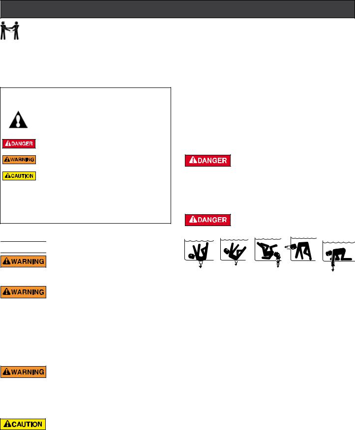
This is the safety alert symbol. When you see this symbol on your system or in this manual, look for one of the following signal words and be alert to the potential for personal injury.
Warns about hazards that can cause death, serious personal injury, or major property damage if ignored.
Warns about hazards that may cause death, serious personal injury, or major property damage if ignored.
Warns about hazards that may or can cause minor personal injury or property damage
if ignored.
NOTE indicates special instructions not related to hazards.
Carefully read and follow all safety instructions in this manual and on equipment. Keep safety labels in good condition; replace if missing or damaged.
When installing and using this electrical equipment, basic safety precautions should always be followed, include the following:


 Do not permit children to use this product.
Risk of Electrical Shock. Connect only to a branch circuit protected by a ground-fault circuit-interrupter
(GFCI). Contact a qualified electrician if you cannot verify that the circuit is protected by a GFCI.
This unit must be connected only to a supply circuit that is protected by a ground-fault circuit-interrupter
(GFCI). Such a GFCI should be provided by the installer and should be tested on a routine basis. To test the GFCI, push the test button. The GFCI should interrupt power. Push the reset button. Power should be restored. If the GFCI fails to operate in this manner, the GFCI is defective. If the GFCI interrupts power to the pump without the test button being pushed, a ground current is flowing, indicating the possibility of an electric shock. Do not use this pump. Disconnect the pump and have the problem corrected by a qualified service representative before using.
This pump is for use with permanent swimming pools and may also be used with hot tubs and spas if so marked. Do not use with storable pools. A permanently-installed
pool is constructed in or on the ground or in a building such that it cannot be readily disassembled for storage. A storable pool is constructed so that it is capable of being readily disassembled for storage and reassembled to its original integrity.
General Warnings
•Never open the inside of the drive motor enclosure. There is a capacitor bank that holds a 230 VAC charge even when there is no power to the unit.
•The pump is not submersible.
•The pump is capable of high flow rates; use caution when installing and programming to limit pumps performance potential with old or questionable equipment.
•Code requirements for the electrical connection differ from state to state. Install equipment in accordance with the National Electrical
Code and all applicable local codes and ordinances.
•Before servicing the pump; switch OFF power to the pump by disconnecting the main circuit to the pump.
•This appliance is not intended for use by persons (including children) of reduced physical, sensory or mental capabilities, or lack of experience and knowledge, unless they have been given supervision or instruction concerning the use of the appliance by a person responsible for their safety.
FAILURE TO FOLLOW ALL INSTRUCTIONS AND
WARNINGS CAN RESULT IN SERIOUS BODILY INJURY OR DEATH. THIS PUMP SHOULD BE INSTALLED AND
SERVICED ONLY BY A QUALIFIED POOL SERVICE PROFESSIONAL. INSTALLERS, POOL OPERATORS AND OWNERS MUST READ THESE WARNINGS AND ALL INSTRUCTIONS IN THE OWNER’S MANUAL BEFORE USING THIS PUMP. THESE WARNINGS AND THE OWNER’S MANUAL MUST BE LEFT WITH THE POOL OWNER.
SUCTION ENTRAPMENT HAZARD: STAY OFF
THE MAIN DRAINANDAWAYFROMALLSUCTION OUTLETS!
THIS PUMP PRODUCES HIGH LEVELS OF SUCTIONAND CREATES A STRONG VACUUM AT THE MAIN DRAIN AT THE BOTTOM OF THE BODYOF WATER.THIS SUCTION IS SO STRONGTHATITCANTRAP ADULTS OR CHILDREN UNDER WATER IF THEY COME IN CLOSE PROXIMITY TO A DRAIN OR A LOOSE OR BROKEN DRAIN COVER OR GRATE.
THE USE OF UNAPPROVED COVERS OR ALLOWING USE OF THE POOLOR SPAWHEN COVERSARE MISSING, CRACKED OR BROKEN CAN RESULT IN BODY OR LIMB ENTRAPMENT, HAIR ENTANGLEMENT, BODY ENTRAPMENT, EVISCERATION AND/OR DEATH.
The suction at a drain or outlet can cause:
Limb Entrapment: When a limb is sucked or inserted into an opening resulting in a mechanical bind or swelling. This hazard is present when a drain cover is missing, broken, loose, cracked or not properly secured.
Hair Entanglement: When the hair tangles or knots in the drain cover, trapping the swimmer underwater. This hazard is present when the flow rating of the cover is too small for the pump or pumps.
Body Entrapment: When a portion of the body is held against the drain cover trapping the swimmer underwater. This hazard is present when the drain cover is missing, broken or the cover flow rating is not high enough for the pump or pumps.
Evisceration/Disembowelment: When a person sits on an open pool (particularly a child wading pool) or spa outlet and suction is applied directly to the intestines, causing severe intestinal damage. This hazard is present when the drain cover is missing, loose, cracked, or not properly secured.
IntelliFlo® Variable Speed Pump Installation and User’s Guide
iii
IMPORTANT PUMP WARNING AND SAFETY INSTRUCTIONS
Mechanical Entrapment: When jewelry, swimsuit, hair decorations, finger, toe or knuckle is caught in an opening of an outlet or drain cover. This hazard is present when the drain cover is missing, broken, loose, cracked, or not properly secured.
NOTE: ALL SUCTION PLUMBING MUST BE INSTALLED IN ACCORDANCE WITH THE LATEST NATIONAL AND LOCAL CODES, STANDARDS AND GUIDELINES.
TO MINIMIZE THE RISK OF INJURY DUE TO SUCTION ENTRAPMENT HAZARD:
•Aproperly installed and securedANSI/ASMEA112.19.8 approved anti-entrapment suction cover must be used for each drain.
•Each suction cover must be installed at least three (3’) feet apart, as measured from the nearest point to nearest point.
•Regularly inspect all covers for cracks, damage and advanced weathering.
•If a cover becomes loose, cracked, damaged, broken or is missing, replace with an appropriate certified cover.
•Replace drain covers as necessary. Drain covers deteriorate over time due to exposure to sunlight and weather.
•Avoid getting hair, limbs or body in close proximity to any suction cover, pool drain or outlet.
•Disable suction outlets or reconfigure into return inlets.
A clearly labeled emergency shut-off switch for the pump must be in an easily accessible, obvious place.
Make sure users know where it is and how to use it in case of emergency.
The Virginia Graeme Baker (VGB) Pool and Spa Safety Act creates new requirements for owners and operators of commercial swimming pools and spas.
Commercial pools or spas constructed on or after December 19, 2008, shall utilize:
(A) A multiple main drain system without isolation capability with suction outlet covers that meet ASME/ANSI A112.19.8a Suction Fittings for Use in Swimming Pools, Wading Pools, Spas, and Hot Tubs and either:
(i)A safety vacuum release system (SVRS) meeting ASME/ANSI A112.19.17 Manufactured Safety Vacuum Release systems (SVRS) for Residential and Commercial Swimming Pool, Spa, Hot Tub, and Wading Pool Suction Systems and/or ASTM F2387 Standard Specification for Manufactured Safety Vacuum Release Systems (SVRS) for Swimming pools, Spas and Hot Tubs or
(ii)A properly designed and tested suction-limiting vent system or
(iii)An automatic pump shut-off system.
Commercial pools and spas constructed prior to December 19, 2008, with a single submerged suction outlet shall use a suction outlet cover that meets ASME/ANSI A112.19.8a and either:
(A)A SVRS meeting ASME/ANSI A112.19.17 and/or ASTM F2387, or
(B)A properly designed and tested suction-limiting vent system, or
(C)An automatic pump shut-off system, or
(D)Disabled submerged outlets, or
(E)Suction outlets shall be reconfigured into return inlets.
For Installation of Electrical Controls at Equipment Pad (ON/OFF Switches, Timers and Automation Load Center)
Install all electrical controls at equipment pad, such as on/off switches, timers, and control systems, etc. to allow the operation (startup, shut-down, or servicing)
of any pump or filter so the user does not place any
portion of his/her body over or near the pump strainer lid, filter lid or valve closures. This installation should allow the user enough space to stand clear of the filter and pump during system start-up, shut down or servicing of the system filter.
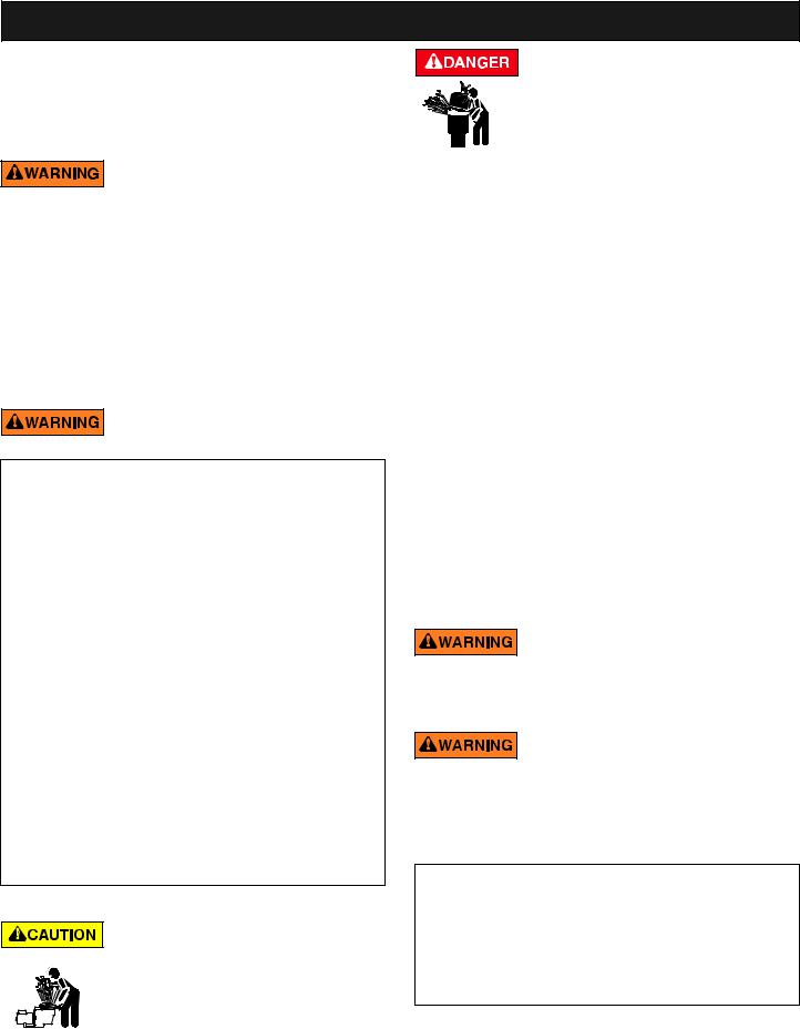
HAZARDOUS PRESSURE: STAND CLEAR OF PUMP AND FILTER DURING START UP
Circulation systems operate under high pressure.
When any part of the circulating system (i.e.
locking ring, pump, filter, valves, etc.) is serviced,
air can enter the system and become pressurized.
Pressurized air can cause the pump housing cover filter lid and valves to violently separate which can result in severe personal injury or death. Filter tank lid and strainer cover must be properly secured to prevent violent separation. Stand clear of all circulation system equipment when turning on or starting up pump.
Before servicing equipment, make note of the filter pressure. Be sure that all controls are set to ensure the system cannot inadvertently start during service. Turn off all power to the pump. IMPORTANT: Place filter manual air relief valve in the open position and wait for all pressure in the system to be relieved.
Before starting the system, fully open the manual air relief valve and place all system valves in the “open” position to allow water to flow freely from the tank and back to the tank. Stand clear of all equipment and start the pump.
IMPORTANT: Do not close filter manual air relief valve until all pressure has been discharged from the valve and a steady stream of water appears. Observe filter pressure gauge and be sure it is not higher than the pre-service condition.
General Installation Information
•All work must be performed by a qualified service professional, and must conform to all national, state, and local codes.
•Install to provide drainage of compartment for electrical components.
•These instructions contain information for a variety of pump models and therefore some instructions may not apply to a specific model. All models are intended for use in swimming pool applications. The pump will function correctly only if it is properly sized to the specific application and properly installed.
Pumps improperly sized or installed or used in applications other than for which the pump was
intended can result in severe personal injury or death. These risks may include but not be limited to electric shock, fire, flooding, suction entrapment or severe injury or property damage caused by a structural failure of the pump or other system component.
The pump can produce high levels of suction within the suction side of the plumbing system. These high
levels of suction can pose a risk if a person comes within the close proximity of the suction openings. A person can be seriously injured by this high level of vacuum or may become trapped and drown. It is absolutely critical that the suction plumbing be installed in accordance with the latest national and local codes for swimming pools.
Warnings and safety instructions for Pentair Water Pool and Spa® pumps and other related products are available at: http://www.pentairpool.com/pool-owner/safety-warnings/ or call (800) 831-7133 for additional free copies of these instructions.
Please refer to http://www.pentairpool.com/pool-owner/ safetywarnings/ for warning and safety instructions related to the IntelliFlo® Variable Speed Pump.
SAVE THESE INSTRUCTIONS
IntelliFlo® Variable Speed Pump Installation and User’s Guide
1
Section 1
Pump Overview
Introduction
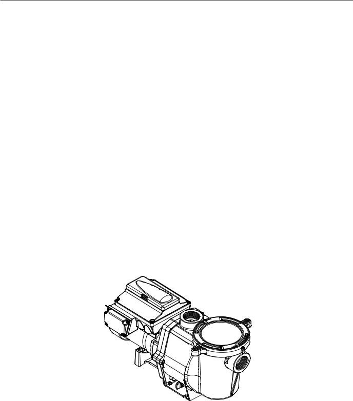
The IntelliFlo® Variable Speed pump is well suited for all of your pool, spa, cleaner, waterfall and other water applications. Using the control panel, IntelliFlo® can use one of the four selectable preset speeds or the pump speed can be adjusted to run at a specific speed. Advanced energy conservation features ensure that your filtration system is operating at peak efficiency.
The IntelliFlo® pump is a variable speed pump that can use up to eight speeds that can be adjusted to run at specific speeds and time intervals. The IntelliFlo® Variable Speed pump out performs all conventional pumps in its class.
The pump can operate from 450 RPM to 3450 RPM with preset speeds of 750, 1500, 2350 and 3110 RPM. The pump can be adjusted from the control panel to run at any speed between 450 RPM to 3450 RPM for different applications. The pump control panel alarm LED and error messages warn the user against under and over voltage, high temperature, over current and freeze protection with user defined minimum and maximum speed presets.
External Control
The IntelliFlo® pump can communicate with an IntelliTouch®, EasyTouch®, or SunTouch® control system or the IntelliComm® communication center via a two-wire RS-485 communication cable. The communication cable is included with the IntelliFlo® Variable Speed pump. EasyTouch® and IntelliComm® can remotely control the IntelliFlo® Variable speed four preset speeds. The IntelliTouch® system can be configured to control a total of eight speeds. The pump’s address and other pump functions are accessed from the pump’s control panel.
IntelliFlo® Variable Speed Pump
IntelliFlo® Variable Speed Pump Installation and User’s Guide
2
Features
Adjusts to various pool sizes Prevents thermal overload
Detects and prevents damage from under and over voltage conditions Protects against freezing
Communicates with EasyTouch, IntelliTouch or SunTouch control systems or an IntelliComm communication center via a two-wire RS-485 cable connection
Easy to use operator control panel
Operator control panel buttons for speed control Built-in strainer pot and volute
Ultra energy-efficient TEFC Square Flange Motor
Compatible with most cleaning systems, filters, and jet action spas Motor assembly features permanent magnet synchronous motor Heavy-duty, durable construction designed for long life
12 Programmable Speeds
Eight Set speeds
Schedule
Duration
Manual
Four IntelliComm speed modes Priming Feature
Load Sensing
Enable or Disable
Lock out protection
Four Digit password
Enable or Disable LCD Display
Power and Speed
Text Alerts
Antifreeze Protection
Adjustable speed
Adjustable Temperatures
Enable and Disable in stand alone Additional Features
Clock and Timer
Maximum and Minimum Speed Limits Quick Clean Mode
Address up to 16 pumps
Service Features
Timeout Mode
IntelliFlo® Variable Speed Pump Installation and User’s Guide
3
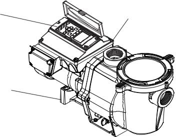
IntelliFlo® Drive Assembly and Control Panel
The IntelliFlo® drive assembly consists of an operator control panel and the system electronics that drive the motor. The drive microprocessor controls the motor by changing the frequency of the current it receives together, with changing the voltage to control the rotational speed.
Operator Control Panel,
Buttons and LED
AC Power Connection
Compartment 
Motor Stand
Communication port for connection to EasyTouch, IntelliTouch or SunTouch control system or IntelliComm communication center via two-wire RS485 cable.
IntelliFlo® Variable Speed Drive Assembly
IntelliFlo® Variable Speed Motor Features
•Permanent Magnet Synchronous Motor (PMSM)
•High efficiency (3450 RPM 92% and 1000 RPM 90%)
•Superior speed control
•Operates at lower temperatures due to high efficiency
•Same technology as deployed in hybrid electric vehicles
•Designed to withstand outdoor environment
•Totally enclosed fan cooled
•Three-phase motor
•56 Square Flange
•Six-Pole
•Low noise
IntelliFlo® Variable Speed Pump Installation and User’s Guide

4
Section 2
Operator Control Panel
This section describes the IntelliFlo® Variable Speed pump operator controls and LEDs.
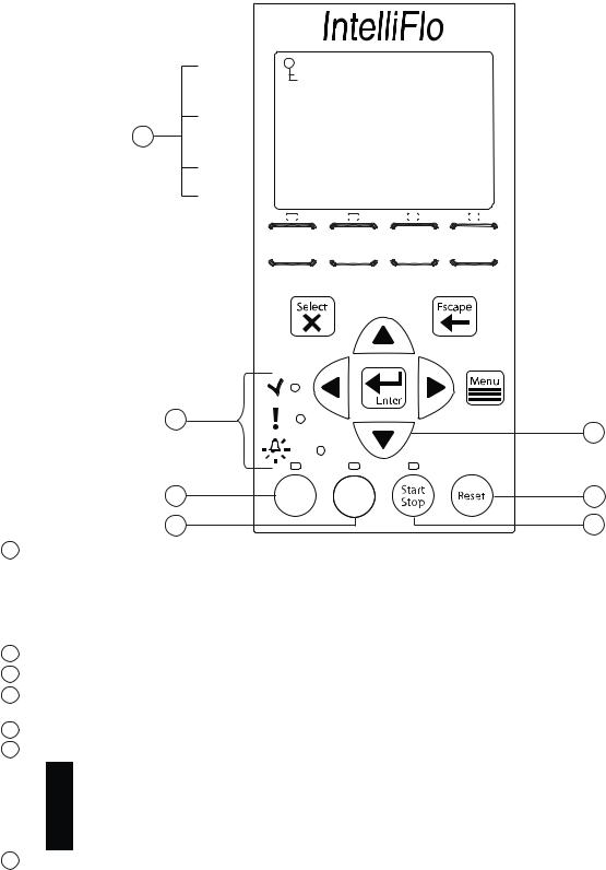
IntelliFlo® Operator Control Panel
®
Line 1: Key Lockout Icon |
12:15 |
Current Time |
|
Line 2: |
|
750 RPM |
Current Speed |
||
|
|
|
|
||
Line 3: Countdown Time |
T 0.00 |
150 WATTS |
Current Power Usage |
||
Line 4: |
Running Speed 1 |
|
Current Feature Running |
||
1 |
Speed |
Speed |
Speed |
Speed |
4 |
1 |
2 |
3 |
4 |
||
2 |
|
|
|
|
3 |
5 |
|
|
|
|
6 |
7
8
Quick |
Time |
Clean |
Out |
Controls and LEDs
1Speed 1 button/LED: Press button to select Speed 1 (750 RPM). LED on indicates Speed 1 is active.
2Speed 2 button/LED: Press button to select Speed 2 (1500 RPM). LED on indicates Speed 2 is active.
3Speed 3 button/LED: Press button to select Speed 3 (2350 RPM). LED on indicates Speed 3 is active.
4Speed 4 button/LED: Press button to select Speed 4 (3110 RPM). LED on indicates Speed 4 is active.
5Select button: Displays available menu items or enters edit mode for changing a value on line two of the display.
6Escape button: Moves to next level up in the menu structure, and/or stops editing the current setting.
7Menu button: Accesses the menu items if the pump is stopped.
8Enter button: Saves current menu item setting. Press this button to acknowledge alarms and warning alerts.
IntelliFlo® Variable Speed Pump Installation and User’s Guide
5
Controls and LEDs (Continued)
®
Line 1
Line 2
15
Line 3
Line 4
12:15
750 RPM
T 0.00 150 WATTS
Running Speed 1
|
|
|
|
|
|
|
|
|
|
|
|
|
|
|
|
|
|
|
|
|
|
|
|
|
|
|
|
|
|
|
|
|
|
|
|
|
|
|
|
|
|
|
|
|
|
|
|
|
|
|
|
|
|
|
|
|
|
|
|
|
|
|
|
|
|
|
|
|
|
|
|
|
|
|
|
|
Speed |
|
|
Speed |
|
|
Speed |
|
|
|
Speed |
|
|||||||||||
|
|
|
|
|
|
|
|
|
|
|||||||||||||||
|
1 |
|
|
|
2 |
|
|
|
3 |
|
|
|
4 |
|
|
|
||||||||
|
|
|
|
|
|
|
|
|
|
|
|
|
|
|
|
|
|
|
|
|
|
|
|
|
|
|
|
|
|
|
|
|
|
|
|
|
|
|
|
|
|
|
|
|
|
|
|
|
|
|
|
|
|
|
|
|
|
|
|
|
|
|
|
|
|
|
|
|
|
|
|
|
|
|
14 |
|
|
9 |
|
|
|
|
||
10 |
Quick |
Time |
13 |
|
Clean |
Out |
|||
|
|
|||
11 |
|
|
12 |
9Arrow buttons:
•Up arrow: Move one level up in the menu tree or increase a digit when editing a setting.
•Down arrow: Move one level down in the menu tree or decrease a digit when editing a setting.
•Left arrow: Move cursor left one digit when editing a setting.
•Right arrow: Move cursor right one digit when editing a setting.
10Quick Clean: Duration and speed (RPM) can be preset to save energy. The LED is on when active.
11Time Out: When active (LED on), at the end of a “Time Out” preset time, the pump will run a schedule.
12Start/Stop button: Start or Stop the pump. When the LED is on, the pump is currently running or in a mode to start automatically.
13Reset button: Reset alarm or alert.
14LEDs
On: This green, power LED is on when IntelliFlo® is powered on. Warning: LED is on if a warning condition is present.
 Alarm: The red LED is on if an alarm condition occurs. See “Alerts and Warnings” on page 35.
15Control Panel LCD:
• Line 1 - Key icon indicates password protect mode is active. If password protect is not enabled,
no key icon is displayed.
•Line 2 - Displays the current pump speed (RPM).
•Line 3 - Count down time and Watts
•Line 4 - Current pump status.
IntelliFlo® Variable Speed Pump Installation and User’s Guide

6
Section 3
Operating the Pump
This section describes how to operate the IntelliFlo® pump using the control panel buttons and menu features.
Starting the pump
To start the pump
1.Be sure the pump is powered on and the green power LED is on.
2.Select one of the speed buttons, then press the Start button (LED on) to start the pump.
Stopping the pump
To stop the pump
•Press the Stop button to stop the pump.
Note: The pump can automatically restart if the communication cable is connected.
Servicing Equipment (Disconnect Power to Pump)
•When servicing equipment (filters, heaters, chlorinators etc.), disconnect the communication cable, and switch OFF circuit breaker to remove power from the pump.
Operating the IntelliFlo Pump at Preset Speeds
The IntelliFlo® Variable Speed pump is programmed with four default speeds of 750, 1500, 2350 and 3110 RPM. A Speed button is assigned to each of the preset speeds as shown.
To operate the pump at one of the four preset speeds
1.Be sure the pump is powered on and the green power LED is on.
2.Press the Speed button (1- 4) corresponding to the desired preset speed, and release quickly. The LED above the Speed button will come on as shown.
3.Press the Start button. The pump will quickly ramp to the selected preset speed.
LED lit |
|
|
|
Speed |
Speed |
Speed |
Speed |
1 |
2 |
3 |
4 |
Adjusting the pump speed
1.While the pump is running, press the Up Arrow to increase speed setting.
2.Press the Down Arrow to decrease speed Setting.
3.Press and hold down a Speed Button for three (3) seconds to save speed to the button or press the Enter button to save the speed.
IntelliFlo® Variable Speed Pump Installation and User’s Guide
7
Pump Operating Modes
The IntelliFlo® Variable Speed pump can be programmed three ways:
1.Manual Operation: Speed buttons 1-4 can be programmed for Manual operation. This means the speed button is pressed and then the start button and the pump runs a programmed speed. Speeds 5-8 cannot be programmed for Manual operation because there are no buttons associated with them.
To operate the pump in Manual Mode, press one of the four speed buttons, and press the Start/Stop button to run the assigned speed for that button. When the pump is running a Manual Speed Setting (speed 1, 2, 3 or 4 button pressed manually) and a scheduled speed is set to run, the scheduled speed will take priority regardless of speed (RPM) assigned to each button. When the Scheduled Speed’s time is over, it will not revert back to the manually pressed speed. If the pump is running a schedule and a speed button is pressed manually, the pump will run the manually selected speed until the next scheduled speed program.
2.Egg Timer (Duration): Speeds 1-4 can be programmed to run for a duration of time once pressed. This means that the Speed button is pressed and then the start button and the pump runs a programmed speed and the speed will turn off at the end of a preprogrammed amount of time. Speeds 5-8 have no direct pump speed buttons and therefore cannot be programmed with an Egg-Timer.
3.Schedule: The speed button can be programmed to turn on and off at a certain time. The LED above the Start/Stop button must be lit for the pump to run schedules. When a speed is set to run in Schedule mode it can still be operated manually. When a speed is programmed to run 23 hours and 59 minutes per day it will not turn off. For example, for the pump to run 24 hours per day, program the pump to start at 8:00 AM and stop at 7:59 AM.
Programming the Pump
When the pump is running, a manual speed and password time out is activated (see page 12) the pump can be turned off but it cannot be turned back on. Pressing the Start/Stop button places it in the Running Schedule mode. Therefore, it will only run Speeds that are Scheduled to come on at their scheduled Start Time.
IntelliFlo® Variable Speed Pump Installation and User’s Guide

8
IntelliFlo® Variable Speed Pump Menus
MENU
SETTINGS
(page 9)
Press MENU button to access menus
|
Pump Address |
|
|
|
(1-16) Default: ADDRESS 1 |
|
|
|
|
|
|||
|
|
|
|
|
|
(hr:mm) Default: 12:00 AM |
|
Set Time |
|
|
|
||
|
|
|
||||
|
|
|
|
|
|
AM/PM |
|
Set AM/PM |
|||||
|
|
|
|
|||
|
|
|
|
|
|
24 hr. |
|
|
|
|
|
|
|
|
|
|
|
|
|
Fahrenheit - Default: F° |
|
Temperature Unit |
|
|
|
||
|
|
|
|
|||
|
|
|
|
|
|
C° Celsius |
|
|
|
|
|
|
|
|
|
|
|
|
|
(1-5) Default 3 |
|
Screen Contrast |
|
|
|
||
|
|
|
|
|||
|
|
|
|
|
|
English - Default: English |
|
Language |
|
|
|
||
|
|
|
|
|||
|
|
|
|
|
|
(450 RPM - 1700 RPM) - Default: 450 RPM |
|
Set Min Speed |
|
|
|
||
|
|
|
|
|||
|
|
|
|
|
|
(1900 RPM - 3450 RPM) - Default: 3450 RPM |
|
Set Max Speed |
|
|
|
||
|
|
|
|
|||
|
|
|
|
|
|
Disabled/Enabled - Default: Disabled |
|
PASSWORD |
|
|
|
||
|
|
|
|
|||
|
|
|
|
|
|
Password Time Out (1 min. - 6 hours) Default:10 minutes |
|
|
|
|
|
|
|
|
|
|
|
|
|
Enter Password (xxxx) Default: 1234 |
|
|
|
|
|
|
|
SPEED 1-8
(page 14)
EXT CONTROL
(page 15)
FEATURES
(page 15)
PRIMING
(page 17)
ANTI FREEZE
(page 20)
|
Speed 1 (1-4) |
|
|
|
|
Manual |
|
|
|
|
|
|
|
|
|
|
|
Set Speed - Default: MANUAL |
|
|
|
|
|
|
|
|
|
|
|
|
|
|
|
|
|
||||
|
|
|
|
|
|
|
Schedule |
|
|
|
|
|
|
|
|
Set Speed |
|||
|
|
|
|
|
|
|
|
|
|
|
|||||||||
|
|
|
|
|
|
|
|
|
|
|
|
|
|
|
|
|
|
|
Set Start Time |
|
|
|
|
|
|
|
|
|
|
|
|
|
|
|
|||||
|
|
|
|
|
|
|
|
|
|
|
|
|
|
|
|
|
|||
|
|
|
|
|
|
|
Egg Timer |
|
|
|
|
|
|
|
Set Stop Time |
||||
|
|
|
|
|
|
|
|
|
|
|
|
|
|||||||
|
|
|
|
|
|
|
|
|
|
|
|
|
|
Set Speed |
|||||
|
|
|
|
|
|
||||||||||||||
|
|
|
|
|
|
|
|
|
|||||||||||
|
|
|
|
|
|
|
Disabled |
|
|
|
|
|
|
|
|
|
Time |
||
|
|
|
|
|
|
|
|
|
|
|
|
|
|
|
|||||
|
Speed |
5 (5-8) |
|
|
|
|
|
|
|
|
|
Default: Disabled |
|||||||
|
|
|
|
|
|
|
|
|
|||||||||||
|
|
|
|
|
|
|
Schedule |
|
|
|
|
|
|
|
|
Set Speed |
|||
|
|
|
|
|
|
|
|
|
|
|
|
|
|
||||||
|
|
|
|
|
|
|
|
|
|
|
|
|
|
|
|
|
|
Set Start Time |
|
|
|
|
|
|
|
|
|
|
|
|
|
|
|
|
|
|
|
||
|
|
|
|
|
|
|
|
|
|
|
|
|
|
|
|
|
|
|
Set Stop Time |
|
|
|
|
|
|
|
|
|
|
|
|
|
|
|
|
|
|
||
|
Program 1 |
|
|
|
|
Speed - Default: 750 RPM |
|||||||||||||
|
|
|
|
||||||||||||||||
|
|
|
|
|
|
|
Speed - Default: 1500 RPM |
||||||||||||
|
Program 2 |
|
|
|
|||||||||||||||
|
|
|
|
||||||||||||||||
|
|
|
|
|
|
|
Speed - Default: 2350 RPM |
||||||||||||
|
Program 3 |
|
|
|
|||||||||||||||
|
|
|
|
||||||||||||||||
|
|
|
|
|
|
|
Speed - Default: 3110 RPM |
||||||||||||
|
Program 4 |
|
|
|
|||||||||||||||
|
|
|
|
||||||||||||||||
|
|
|
|
|
|
|
Time Out Duration (1 min. to 10 hrs.) Default: 3 hours |
||||||||||||
|
Time Out |
|
|
|
|||||||||||||||
|
|
|
|
||||||||||||||||
|
|
|
|
|
|
|
Set Speed (450 -3450 RPM) Default: 3450 RPM |
||||||||||||
|
Quick Clean |
|
|
|
|
||||||||||||||
|
|
|
|
||||||||||||||||
|
|
|
|
|
|
|
Time (1 min. to 10 hrs.) Default: 10 minutes |
||||||||||||
|
|
|
|
|
|
||||||||||||||
|
|
|
|
|
|
|
Default: Enabled |
||||||||||||
|
DISABLED/ENABLED |
|
|
|
|||||||||||||||
|
|
|
|
||||||||||||||||
|
|
|
|
|
|
|
(1 min. to 30 min.) Default: 11 minutes |
||||||||||||
|
MAX PRIMING TIME |
|
|
|
|
||||||||||||||
|
|
|
|
||||||||||||||||
|
|
|
|
|
|
|
(1 - 100%) Default: 1 |
||||||||||||
|
PRIMED SENSITIVITY |
|
|
|
|||||||||||||||
|
|
|
|
||||||||||||||||
|
|
|
|
|
|
|
(1 second - 10 minutes) Default: 20 seconds |
||||||||||||
|
PRIMING DELAY |
|
|
|
|||||||||||||||
|
|
|
|
|
|||||||||||||||
|
|
|
|
|
|
|
Disabled / Enabled - Default: Enabled |
||||||||||||
|
DISABLED/ENABLED |
|
|
|
|||||||||||||||
|
|
|
|
||||||||||||||||
|
|
|
|
|
|
|
Set Speed (450 RPM - 3450 RPM) Default 1000 RPM |
||||||||||||
|
SET SPEED |
|
|
|
|
||||||||||||||
|
|
|
|
|
|||||||||||||||
|
|
|
|
|
|
|
40° F - 50° F (4.4° C - 10° C) Default: 40° F (4.4° C) |
||||||||||||
|
PUMP TEMPERATURE |
|
|
|
|
||||||||||||||
|
|
|
|
|
|||||||||||||||
IntelliFlo® Variable Speed Pump Installation and User’s Guide
9
IntelliFlo® Pump Menus
The IntelliFlo® pump menu descriptions are as follows:
Settings: Pump Address
The IntelliFlo® pump address needs to be changed when there is more than one IntelliFlo® pump on an automation system. This allows the automation system to know which pump to send a command. The “Pump Address” setting is used when the IntelliFlo® pump is connected via the RS-485 COM port to an IntelliTouch®, EasyTouch®, SunTouch® or IntelliComm® system. The default pump address is #1. When connected to EasyTouch®, SunTouch® or IntelliComm® the pump only communicates with address #1. The pump address can be set from 1-16. However, IntelliTouch® can communicate to four (1-4) IntelliFlo® pumps.
Note: IntelliFlo® pumps cannot be connected in series with other pumps.
To access the Settings menu:
1.Be sure the green power LED is on and the pump is stopped.
2.Press the Menu button. “Settings” is displayed.
3.Press the Select button. “Pump Address” is displayed. The Factory default setting is address “1.”
4.To change the pump address, press the Select button. The first digit “1” selected.
5.Press Up or Down arrow button to change the address number from 1-16.
6.Press the Enter button to save the setting. To cancel any changes, press the Escape button to exit edit mode without saving.
7.Press the Escape button to exit.
Settings: Set Time
Use “Set Time” to set the IntelliFlo® system time. The IntelliFlo® system clock controls all scheduled start and stop times, functions, and programmed cycles. The system clock can store the correct time for up to 96 hours after power is shut off. The IntelliFlo® will retain the time memory for 96 hours before a reset is needed.
To access the Set Time menu:
1.Check that the green power LED is on.
2.Press the Menu button. “Settings” is displayed.
3.Press the Select button. “Pump Address” is displayed.
4.Use the Up or Down arrow button to scroll to “Set Time”
5.Press the Select button. The cursor will appear in the Minutes column.
6.Press Up or Down arrow button to set the time.
7.Press the Enter button to save the setting. To cancel any changes, press the Escape button to exit edit mode without saving.
8.Press the Escape button to exit.
IntelliFlo® Variable Speed Pump Installation and User’s Guide
10
Settings: Set AM/PM or 24 Clock
This setting is for changing the pump’s time clock from regular time (AM/PM) to a 24 hour clock. For example, Midnight (12:00 AM) is 0000 hr., 8:00 AM is 0800 hr., and 11:00 PM is 2300 hr.
To access the AM/PM or 24 hr. menu:
1.Check that the green power LED is on.
2.Press the Menu button. “Settings” is displayed.
3.Press the Select button. “Pump Address” is displayed.
4.Use the Up or Down arrow button to scroll to “AM/PM.”
5.Press the Select button to change the setting.
6.Press Up or Down arrow button to choose between 24 hr. and AM/PM.
7.Press the Enter button to save the setting. To cancel any changes, press the Escape button to exit edit mode without saving.
8.Press the Escape button to exit.
Settings: Set Temperature Unit
Use this setting to set the temperature unit to Celsius (°C), or Fahrenheit (°F). The IntelliFlo® AntiFreeze protection feature (see page 20) can be set to either Fahrenheit or Celsius.
To access the Temperature Units menu:
1.Check that the green power LED is on.
2.Press the Menu button. “Settings” is displayed.
3.Press the Select button. “Pump Address” is displayed.
4.Use the Up or Down arrow button to scroll to “Temperature Units” menu item. The factory default setting is “F” (Fahrenheit).
5.Press the Select button. “F” is displayed.
6.Press Up or Down arrow button to choose between Celsius (°C), or Fahrenheit (°F).
7.Press the Enter button to save the setting. To cancel any changes, press the Escape button to exit edit mode without saving.
8.Press the Escape button to exit.
Settings: Screen Contrast Level
This setting changes the contrast of the LCD screen. The default setting is 3. Screen contrast levels can be adjusted from 1 to 5 units for low or high lighting conditions.
To access the Temperature Units menu:
1.Check that the green power LED is on.
2.Press the Menu button. “Settings” is displayed.
3.Press the Select button. “Pump Address” is displayed.
4.Use the Up or Down arrow to scroll to “Contrast level.
5.Press the Select button. Screen will show current contrast setting number. The default is “3”.
6.Press the Select button to change the setting. Number will highlight.
7.Press the Enter button to save the setting. To cancel any changes, press the Escape button to exit edit mode without saving.
8.Press the Escape button to exit.
IntelliFlo® Variable Speed Pump Installation and User’s Guide
 Loading...