How it Works
Log In / Sign Up
Buy Points
How it Works
FAQ
Contact Us
Questions and Suggestions
Users
Peerless Industries
Loading...
P
PLP-NEC61
PLP-PAN65
PLP-UN-1
2
PLP-UNLP
3
PLP-UNLP-S
3
PLP-UNL-S
3
PLP-UNM
3
PLP-UNMP
PLP-UNM-S
2
PLP-V100
3
PLP-V2X1
3
PLP-V2X2
3
PLP-V3X2
2
PLP-V3X3
4
PLP-V4X2
3
PLP-V4X3
2
PLP-V4X4
2
PLP-V5X2
PLP-V6X2
2
PLP-V6X4
2
PLP-V6X5
PLP-V6X6
2
PLP-V84X
PLP-V8X4
2
PLP-V8X4-LG
PLP-V9X6
PLS-50F25AL01-04
PLS-50F25AL03-04
PLS-65F25AL02-08
PLS-65F25AL04-04
PLS-75F25AL02-08
PLS-75F25AL04-08
PLT-BLK
4
PLT UNL
PM 13
PM 13S
PM 13W
PM 20
PM 20C
PM 20S
PM 20W
PM 27
PM 27C
PM 27S
PM 27W
PM47S
2
PM610
PM610G
PM732W
Polycarbonate Tweeter
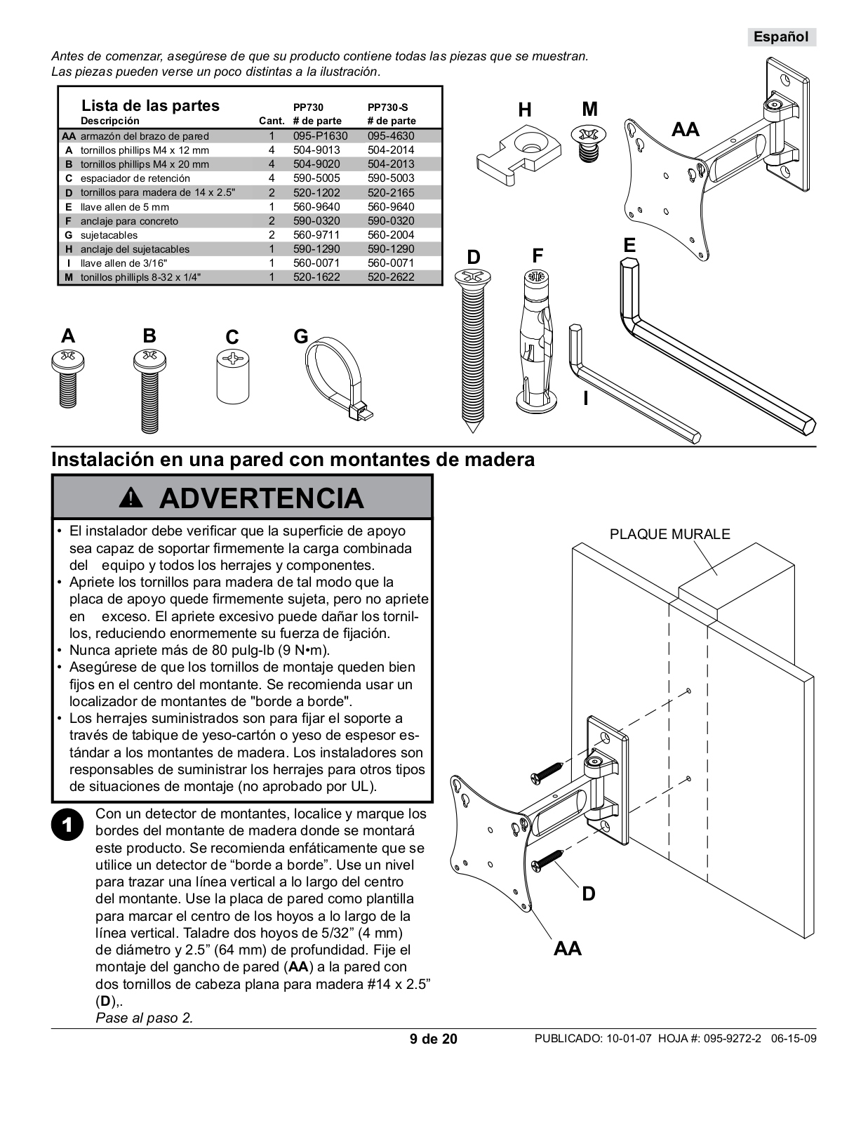
PP730
4
PP730-S
2
PP740
5
PP740-S
2
PPB-S
PPC-W
PPF
PPF-S
PPF-S-W
PPF-W
2
PRG-1
PRG-1S
2
PRG-1W
2
PRG3-EXA
2
PRG3-EXB
2
PRG-EXA
PRG-EXA-S
PRG-EXA-W
3
PRG-EXB
2
PRG-EXB-S
PRG-EXB-W
3
PRG-EXC
3
PRG-EXC-S
PRG-EXC-W
4
PRGS-455
3
PRGS-ALU0811
PRGS-UNV
3
PRGS-UNV-S
PRGS-UNV-W
2
PRG-UNV
2
PRG-UNV-B
2
PRG-UNV-S
2
PRG-UNV-W
3
PRMA100
PRMA2X1
PRMA4X4
PRMALU
PRMF100
PRMF2X1
PRMF2X2
PRMFLU
PRMFMU
PRMP100
PRMP2X1
PRMT100
PRMT2X1
PRMT2X2
PRMTLU
PRMTMU
PRS 145
Loading...
Loading...
Nothing found
PP730
Datasheet
2 pgs
243.29 Kb
0
Specsheet
2 pgs
351.13 Kb
0
User Manual
20 pgs
3.7 Mb
0
User Manual
2 pgs
213.57 Kb
0
Table of contents
Loading...
Peerless Industries PP730, PP730-S User Manual
...
Peerless Industries User Manual
Download
Specifications and Main Features
Frequently Asked Questions
User Manual
Download
Loading...
+
hidden pages
Unhide
You need points to download manuals.
1 point = 1 manual.
You can buy points or you can get point for every manual you upload.
Buy points
Upload your manuals