

Page 1
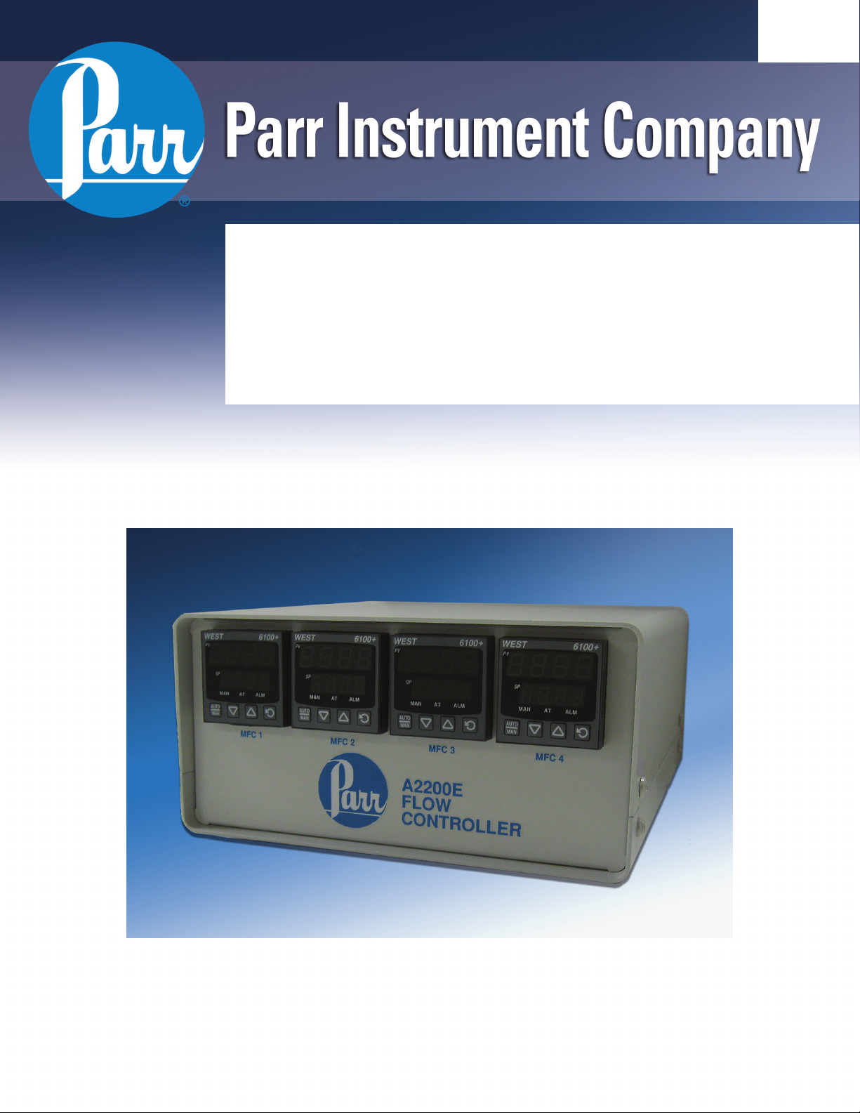
A2200E
Flow Controller
Operating Instruction Manual
594M
Page 2

Flow Controller
Preface
Related Instructions — 3
Scope — 3
Applications — 3
Customer Service — 3
Explanation of Symbols — 4
Safety Information — 4
Intended Usage — 4
Unpack Carefully — 4
Cleaning & Maintenance — 5
Provisions for Lifting and Carrying — 5
General Specifications — 5
Electrical Ratings— 5
Environmental Conditions— 5
Installation
General Instructions — 6
Inputs/Outputs — 6
Main power switch — 7
Protective Fuses — 7
Fuses— 7
Figures
A2200E Rear Panel — 6
Back View A2200E Flow Controller — 7
Instructions for the A2200E Flow Controller
Navigating the Menus — 9
Configuration Mode - ConF — 9
Setup Mode - SEtP — 9
Automatic Tune Mode – Atun — 9
Operation Mode - OPtr — 9
Parts List
Fuses — 10
Mains Supply Cords — 10
2
Parr Instrument Company
Page 3

Flow Controller
Preface
Related Instructions
The following Parr publications are also included to
further your understanding of this instrument and
its component parts:
No. Description
201M Limited Warranty
Scope
These instructions cover the installation and
operation of Parr Model A2200E Flow Controller as
used with Parr Laboratory Reactors and Pressure
Vessels. The users should study the instructions
carefully before using any of these controllers so
that they will fully understand the capabilities of
this equipment and the safety precautions to be
observed in its operation.
Applications
These units are designed specifically for use with
Parr reactors and pressure vessels and are to be
used only with Parr equipment.
Customer Service
Questions concerning the installation or operation of this instrument
can be answered by the Parr Customer Service Department:
1-309-762-7716 • 1-800-872-7720 • Fax: 1-309-762-9453
E-mail: parr@parrinst.com • http://www.parrinst.com
www.parrinst.com
3
Page 4
Flow Controller
Explanation of Symbols
I On position
O Off Position
~ Alternating Current (AC)
This CAUTION symbol may be present on the Product Instrumentation
and literature. If present on the product, the user must consult the
appropriate part of the accompanying product literature for more
information.
Protective Earth (PE) terminal. Provided for connection of the
protective earth (green or green/yellow) supply system conductor.
Safety Information
To avoid electrical shock, always:
1. Use a properly grounded electrical outlet of
correct voltage and current handling capability.
2. Ensure that the equipment is connected to
electrical service according to local national
electrical codes. Failure to properly connect may
create a fire or shock hazard.
3. For continued protection against possible
hazard, replace fuses with same type and rating
of fuse.
4. Disconnect from the power supply before
maintenance or servicing.
To avoid personal injury:
1. Do not use in the presence of flammable or
combustible materials; fire or explosion may
result. This device contains components which
may ignite such material.
2. Refer servicing to qualified personnel.
Intended Usage
This controller has been designed for use with
Parr Pressure Vessels and Reactors. It has been
designed, built, and tested to strict physical
and electrical standards. However, it is the
user’s responsibility to install and operate it in
conformance with local pressure and electrical
codes.
If the instrument is used in a manner not specified
by Parr Instrument Company, the protection
provided by the equipment may be impaired.
Establish training procedures to ensure that any
person handling the equipment knows how to use it
properly.
Unpack Carefully
Unpack the equipment carefully and check all the
parts against the packing list. If shipping damage is
discovered, report it immediately to the delivering
carriers. Examine the components closely for any
loose parts or shipping damage and be sure to
check all layers of packing materials thoroughly so
as not to overlook any parts which might otherwise
be discarded.
4
Parr Instrument Company
Page 5

Flow Controller
Cleaning & Maintenance
Periodic cleaning may be performed on the exterior
surfaces of the controller with a lightly dampened
cloth containing mild soap solution. All power
should be disconnected and the power cord should
be unplugged when cleaning the A2200E Controller.
There are no user serviceable parts inside the
product other than what is specifically called
out and discussed in this manual. Advanced
troubleshooting instructions beyond the scope
of this manual can be obtained by calling Parr
Instrument Company in order to determine which
part(s) may be replaced or serviced.
Provisions for Lifting and Carrying
Before moving the instrument, disconnect all
connections from the rear of the apparatus. Lift the
instrument by grabbing underneath each corner.
General Specifications
Environmental Conditions
This instrument is intended to be used indoors.
Operating: 15 ºC to 40 ºC; maximum relative
humidity of 80% non-condensing. Installation
Category II (over voltage) in accordance with IEC
664.
Pollution degree 2 in accordance with IEC 664.
Altitude Limit: 2,000 meters.
Storage: -25 ºC and 65 ºC; 10% to 85% relative
humidity.
Caution!
Do not use in hazardous atmospheres.
Electrical Ratings
115/230VAC, 3.0 Amps max, 50/60 Hz
Before connecting a controller to an electrical outlet,
the user must be certain that the electrical outlet has
an earth ground connection and that the line, load
and other characteristics of the installation do not
exceed the following limits:
Voltage: Fluctuations in the line voltage should not
exceed 10% of the rated nominal voltage shown on
the data plate.
Frequency: Controllers can be operated from either
a 50 or 60 Hertz power supply without affecting their
operation or calibration.
Current: The total current drawn should not exceed
the rating shown on the data plate on the controller
by more than 10 percent.
www.parrinst.com
5
Page 6

Flow Controller
Installation
General Instructions
Set the controller near the reactor on a sturdy bench
or table where there is convenient access to an
electrical outlet capable of carrying the appropriate
current. Leave a space of at least twelve inches
between the controller and the reactor so that the
controller will not be affected by radiant heat.
Inputs/Outputs
Up to 4 MFC I/O connectors and corresponding meters can be supplied with each A2200E. The A2200E
I/O’s are to only be used with Parr approved controllers. The interface is designed for mass flow controllers which are specified during the ordering process.
An interface cable is supplied for each I/O.
With the A2200E powered off, attach the provided
I/O cable(s) to each MFC. Then attach the opposing
end to the A2200E Flow Controller.
If more than one MFC has been supplied it is recommended that each I/O be identified as to which MFC
is connected.
A2200E Rear Panel
Attach the supplied power cord to the POWER
INPUT connector located on the rear panel of the
A2200E Flow Controller.
Plug the power cord into a properly grounded
electrical supply outlet.
6
Parr Instrument Company
Page 7

Back side
Flow Controller
Back View A2200E Flow Controller
Main power switch
This switch will cut off power to the controller.
Protective Fuses
Main fuses are mounted on the back panel of the
flow controller. These fast acting, 250VAC, 4 amp
fuses are intended to protect the controller and supply in case of a fault condition.
Warning:
Unplug unit before servicing. For continued protection against possible hazard,
replace fuses with same type and rating of
fuse.
Fuses
The following are A2200E Controller fuses which are
intended to be field serviceable.
Fuse Rating Part number
Main Fuse(s) Fast acting, 4
Amp, 250VAC
1434E
www.parrinst.com
7
Page 8

Flow Controller
Instructions for the A2200E Flow Controller
Each A2200E can be supplied with up to four I/O’s.
These I/O’s are used to interface the Mass Flow Controllers on the corresponding reactor system.
The AUTO/MAN key is used only during the pro-
gramming process. It is used to “set” a new value
for a displayed variable. It is also used for other
functions within the meter not specific to the application of the A2200E.
The Up and Down Arrow keys are used to increment
values for each displayed variable.
The SP indication displays the current set point
value which relates to a scaled linear output voltage
or current transmitted to the corresponding mass
flow controller.
The set point can be changed by pressing the Return
key (Circular Arrow) once while in the operation
mode. SP will now be displayed in the SP position.
Use the Up or Down arrow key to select the flow
rate you would like to use. Pressing the Return key
will return the display to normal operation.
In modes other than operation, the SP display indicates a specific variable and the PV display indicates
the current value for that variable. If the PV display
is flashing the current value displayed has not yet
been set and this is done using the AUTO/MAN key.
Each unit is locked with pre-programmed specifications. For troubleshooting or making changes to the
programming follow the instructions below.
The Return key (circular arrow) is used for navigating through each variable in the different mode
menus.
In operation mode on the normal operating display,
the PV indication relates to the flow value transmitted from the Mass Flow Controller. As supplied the
PV value represents the flow in units of SCCM (Standard Cubic Centimeters per Minute; where standard
is 0 °C and 1 ATM.
8
Parr Instrument Company
Page 9

Flow Controller
Navigating the Menus
To navigate to the menu select mode, hold down the
Return key and press the Up Arrow key. To navigate
in the select mode press the Up Arrow or Down Ar-
row key and then the Return key to enter the chosen
mode.
Once in the desired mode press the Return key to
navigate to each parameter, use the Up Arrow or
Down Arrow to change the respective parameter
value. Pressing the Auto/Man key or pressing the
Return key will save the new value.
Configuration Mode - ConF
Note: There are software “locks” in place to change certain
parameters.
To enter the configuration mode, cLoc = 10
*Remember to press the AUTO/MAN key to save
any new value.
Operation
Mode
InPt 0_5 0-5VDC
ruL * Upper range flow
rLL 0 Lower range flow
dPoS 0 Decimal position
CtYP SnGL Primary Control
CtrL rEv Reverse Acting
ALA1 nonE No Alarm 1
ALA2 nonE No Alarm 2
LAEn diSA
Inhi nonE
USE1 rEtS Retransmit SP output
tyP1 0_5 0 to 5Vdc output 1
ro1H * Upper range flow
ro1L 0 Lower range flow
diSP 1
CLoc 10 Configuration Mode
Select
type/value
Comment
value of MFC
value of MFC
value of MFC
value of MFC
Lock Code
Setup Mode - SEtP
To enter setup mode, uLoc = 20
Operation
Mode
FiLt 2.0
OFFS 0 PV offset value
PPLJ Current Primary Out-
Pb_P 0
diFP 0.1
SPuL ro1H value from Con-
SPLL 0
APt diSA Auto Pre-tune
PoEn diSA Manual Control Select
SPr diSA Set point ramp shown
rP blank
SP Current setpoint value
SLoc 20 Setup Mode Lock Code
Automatic Tune Mode – Atun
To enter Tune mode, tLoc = 30
Operation
Mode
Ptun OFF
Stun OFF
tLoc 30
Operation Mode - OPtr
Press the Return key to navigate to the SP value
display. Press the Up Arrow or Down Arrow key to
change the SP value. Press the Auto/Man key to
store the SP value.
Select
type/value
Select type/value
Comment
put Power. Read only
figuration Mode
in operating mode
from operation mode
www.parrinst.com
9
Page 10

Flow Controller
Parts List
Fuses
Fuse Rating Part Number
Main Fuse(s) Fast acting, 4 Amp, 250VAC 1434E
Warning:
For continued protection against possible hazard, replace fuses with same
type and rating of fuse.
External MFC Cables
Part number Description
A1989E MFC harness, voltage input 10 ft (Brooks)
A1989E2 MFC harness, voltage input 20 ft (Brooks)
A1989E3 MFC harness, voltage input 30 ft (Brooks)
Mains Supply Cords
Part number Description
A719E North America, 115VAC, NEMA 5-15P
A719EEE North America, 230VAC, NEMA 6-15P
1465EEE British, 10 Amp, 230VAC
1200EEE European Union, 10 Amp, 230VAC
1858EEE China, 10 Amp, 230VAC
2121EEE Brazil, 10 Amp, 230VAC
10
Parr Instrument Company
Page 11

Revision 08/08/11
 Loading...