

Page 1

A1120HC10 Magnetic Drive
Operating Instruction Manual
656M
Description
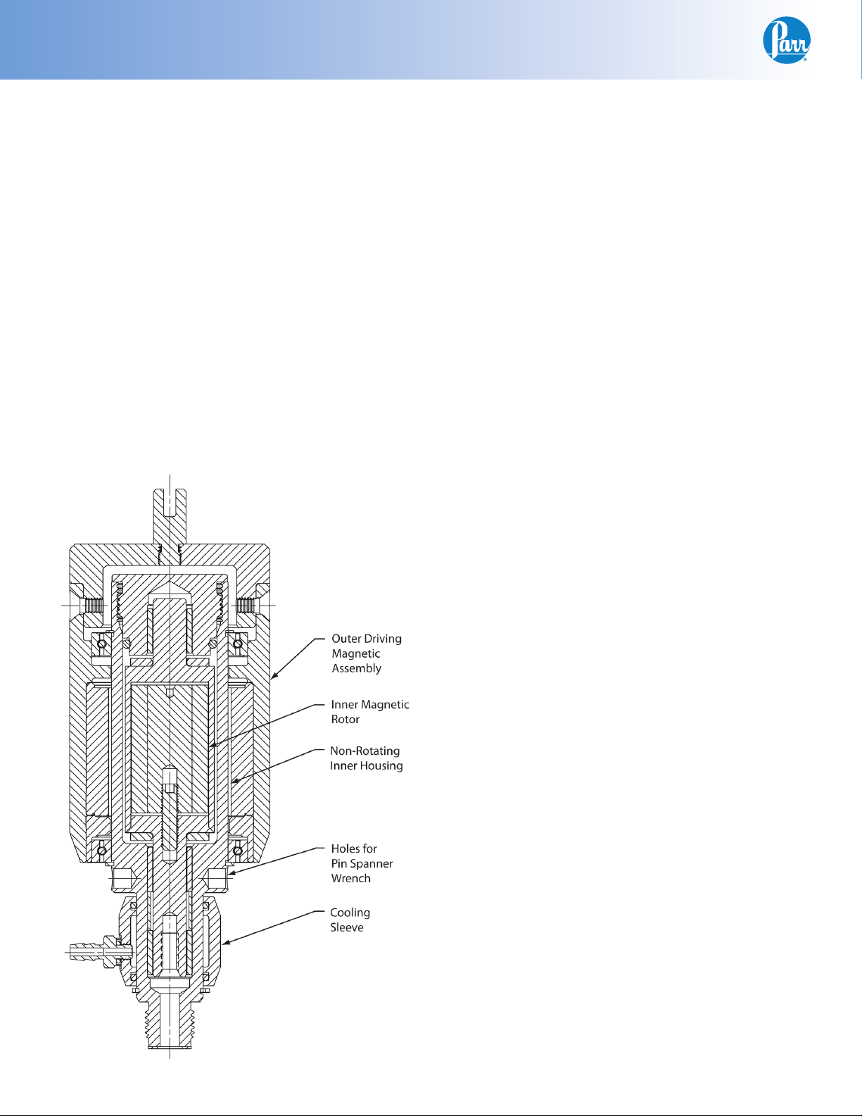
The A1120HC10 magnetic stirrer consists of a internal
rotor assembly with an inner set of magnets and an
outer coupling assembly with a second set of magnets. This assembly is intended for medium viscosity
applications and has a torque rating of 16 in-lbs (1.8
Nm).
The A1120HC10 magnetic stirrer can be used with
both the standard stirrer shaft and impeller(s) or
with a gas entrainment stirrer arrangement. It is
designed to stir at speeds up to approximately 2000
rpm. Maximum stirrer speeds are dependent upon
the viscosity of the vessel contents and the resultant
load on the motor.
This magnetic stirrer requires minimal maintenance;
however, it is important to protect these magnetic
stirrers from the heat in the reactor vessel. To prevent overheating each magnetic drive includes a
cooling sleeve. The cooling sleeve is held in place
on the housing with a snap ring and seals against
the housing with two O-rings. A steady fl ow of cold
water through this sleeve during all vessel operation
at temperatures above 80 ºC is required. Excessive
heating without use of the cooling water will also
damage the O-rings in the cooling sleeve.
Shaft Removal and Installation
To remove the stirrer shaft hold the A1147HC outer
housing of the magnetic drive assembly, and unscrew the stirrer shaft in a counter-clockwise rotation.
To install a replacement or alternate shaft, hold the
outer housing of the magnetic drive fi rmly and screw
in the new shaft.
*Note: It is important to hold the housing
securely when installing any of the stirrer
shafts so that the threads are fully engaged.
Magnetic Drive Maintenance
All rotating parts in Parr magnetic drives are self
lubricating and do not require servicing during normal opera tions. It is advisable, however, to check the
drive from time to time for any evidence of leakage
into the con fi ned space between the inner and outer
rotors. This can be done without removing the drive
from the vessel head and does not require complete
disas sembly. To inspect the drive:
1. Remove the four socket head screws located near
the top of the outer housing and remove the top
cover from the housing. This will expose the plug
which aligns the inner rotor and carries the principle O-ring seal.
2. Unscrew the 1136HC2 plug, using a 264AC5 face
spanner inserted into the two holes at the top
of the plug while holding the rotor fi rmly with
a 264AC4 pin spanner inserted into one of the
holes at the bottom of the assembly above the
cooling sleeve. With the plug removed, the sleeve
bushing and thrust washer at the top of the rotor
will be exposed.
3. Check for any evidence of leakage past the O-ring
seal. If vapors from the reactor have produced
solid deposits in or around the rotor housing, the
deposits will have to be removed to keep them
from destroying the bushings or jamming the
rotor. If cleaning is not re quired, replace the plug
and close the drive.
4. If cleaning is required, the A1125HC inner ro tor
can be removed without removing the entire
drive from the bomb head. To remove: Unscrew
and remove the stir rer shaft from the underside
of the ves sel head. Then push the rotor upward
and out of the housing using the stirrer shaft
or other suitable rod inserted through the shaft
opening.
The inner rotor is a laser-welded, sealed unit which
should require no mainte nance, but it can be damaged by over heating as mentioned earlier.
www.parrinst.com
1
Page 2
A1120HC10 Magnetic Drive
Bushing Removal
Remove the A1125HC inner rotor assembly from the
1135HC4 housing, the upper thrust washer 1132HC
sits on top of the inner rotor. The lower thrust
washer will be loose and also easily removed. Two
1133HC bushings are located in the 1135HC4 housing. The third 1133HC bushing is located in the end
cap. A 1948HC bushing removal tool is recommended to remove these bushings.
Once the inner rotor, thrust washers and bushings
are removed, inspect the housing for any material
deposits that may have collected during operation.
When this unit is completely assembled, there is
about 5 ml of gas space surrounding the inner rotor
assembly. With some applications material may
condense in this area which would necessitate periodic cleaning to remove any build up of debris.
Parr Magnetic Drive
Bushing Installation
There are two 1133HC bushings required in the lower portion of the 1135HC4 housing. A 1947HC bushing installation tool is recommended to install these
bushings. Install one bushing into the housing until
it stops against the lower shoulder of the housing.
The second bushing should be installed so that the
top of the bushing is .020” below the larger diameter area of the housing. The 1947HC installation
tool will accomplish this. This leaves a small internal
space between the two bushings in the housing.
Install the third 1133HC bushing in the end cap.
After cleaning the rotor and the chamber, install the
inner rotor as follows:
1. Set the lower thrust washer into posi tion so
that it will be available to cushion the rotor if it
should accidentally slam into the bottom of the
chamber.
2. Lower the rotor into the chamber slowly, but be
prepared to resist the strong pull of the outer
magnets during this operation. Use the same
rod employed when removing the rotor to resist
the strong pull during assembly.
3. Replace the upper sleeve bushing and the O-ring
in the top plug; insert the upper thrust washer;
lubricate the threads with 424HC2 anti-seize lubricant (careful not to get any on the O-ring) and
screw the top plug into place. Then replace the
top cover and secure it with the four socket head
screws.
2
Parr Instrument Company
Page 3

A1120HC10 Magnetic Drive
The O-Ring Seal
The 1137HCHA O-ring, which seals the top plug in
Parr magnetic drives, is made of PTFE. O-rings of
alternate materials are available to meet specifi c research applications if required. PTFE O-rings should
be replaced each time the drive is re-assembled.
Servicing the Outer Drive
The outer drive is supported by two high quality
sealed ball bearings which do not require lubrication. Any oil leak or noise from the bearing will
indicate that the seal or the bearing has failed and
the bearing must be replaced.
To disassemble the outer drive:
1. Remove the four socket head screws located
near the top of the outer housing; then lift the
cover from the housing to expose the upper
snap ring. Peel the snap ring out of its groove
with a small screwdriver; slide it upward and
remove it.
2. Take a fi rm grip on the outer drive housing and
pull it upward to separate the outer assembly
from the magnetic drive housing. The lower
bearing may not come out with the housing. If
not, remove at this time.
To reassemble the outer drive:
1. Slide the lower spiral snap ring back into its
groove; then slide the lower ball bearing onto
the inner hous ing. The inner magnets should
hold the bearing at the middle of the housing.
2. Slide the outer drive assembly over the rotor,
thereby pushing the lower bearing down against
the lower spiral snap ring. Hold both parts fi rmly
during this step so that the magnets do not slam
the outer drive into place.
3. Insert the upper wave spring into its groove in
the outer drive housing and slide the ball bearing into place against the wave spring, then anchor the bearing by pushing the retaining snap
ring downward until it snaps into its groove
above the bearing. During this step suffi cient
pressure must be applied against the snap ring
to force the wave spring downward and allow
the snap ring to drop into its groove. This can be
done with a pair of screw drivers, using alternating pressure on the snap ring. This must be done
carefully to be sure that the screw drivers do
not slip and damage the seals in the bearings.
To simplify the opera tion, Parr offers a magnetic
drive assem bly tool (Part No. 2086HC) consisting of a properly sized cup which can be pushed
downward against the snap ring to force it into
its groove.
4. Replace the top cover and secure it with the four
socket head screws.
Cooling Sleeve
The A2685HC cooling sleeve mounted on the
1135HC4 magnetic drive body includes two 827HC
O-rings which seal against the body. After extended
operation these O-rings will require replacement.
To replace the O-rings, remove the magnetic stirrer from the vessel head as described previously.
Remove the 825HC retaining ring from the 1135HC4
body and slide the cooling sleeve off. Remove the
O-rings from the inside of the cooling sleeve. Care
must be taken not to scratch the O-ring grooves.
Clean any accumulated lime deposits from the
inside of the sleeve. To reinstall the cooling sleeve,
insert new O-rings into the grooves, moisten the
O-rings with water, slide the sleeve back onto the
housing, and reinstall the 825HC retaining ring.
www.parrinst.com
3
Page 4

A1120HC10 Magnetic Drive
A1120HC10 Magnetic Drive Parts Lists
Item Description
A1125HC Rotor assembly
1132HC Thrust washer
1133HC Bushing
1134HC Spacer
1135HC4 Stirrer housing
1136HC2 Plug
1137HCHA O-ring, PTFE
1138HC Snap ring, external
1138HC2 Snap ring, spiral
1139HC Bearing
1142HC3 Jacket cover
1144HC Wave spring
A1147HC Outer magnetic housing assy
2437HC Drive adapter (Hub)
SA1632FS06 Set screw
A1120HC10 Magnetic Drive Assembly
Cooling Sleeve Assembly
Item Description
2683HC Cooling Sleeve
827HC O-rings
2714HC Hose Barbs
A2685HC Consists of the components listed above
Tools
Item Description
264AC4 Pin Spanner Wrench, 1–½”
1947HC Bushing Installation Tool
1948HC Bushing Removal Tool
424HC2 Anti-Seize Lubricant
NOTE:
1) (*) Parts marked respectively are of corresponding material in assemblies constructed of special material.
2) Shafts are not included as part of A1120HC10.
3) For use with JP0025TB06 tubing.
P
arr Instrument Company
211 53rd Street • Moline, Illinois 61265 USA 1-309-762-7716 • 1-800-872-7720 • Fax: 1-309-762-9453
E-mail: parr@parrinst.com • http://www.parrinst.com
Revision 12/11/12
 Loading...