

Page 1
6755
Solution Calorimeter
Operating Instruction Manual
For models produced after November 2010
593M
Page 2

Table of Contents
Preface
Scope — 1
Related Instructions — 1
Customer Service — 1
Explanation of Symbols — 2
Safety Information — 3
Intended Usage — 3
General Specifi cations — 3
Environmental Conditions — 3
Provisions for Lifting and Carrying — 3
Cleaning & Maintenance — 3
Specifi cations — 3
Chapter 1
Installation
Power Connection — 4
Motor Installation — 4
Thermistor Probe Installation — 4
Chapter 2
Quick Start — 6
Chapter 3
Operation
Menu System — 8
Menu Keys — 8
Control Keys — 8
Programming — 8
Default Settings — 9
Performing an Analysis — 9
Sample Size — 10
Filling the Dewar — 10
Loading a Solid Sample — 10
Loading a Liquid Sample — 10
Installing the Loaded Cover Assembly — 10
Combining the Reactants — 10
Emptying the Calorimeter — 11
Manual Test Sequencing— 11
Automatic Test Sequencing— 11
Chapter 4
Menu Descriptions
Main Menu — 12
Calorimeter Operation Menu — 12
Operating Controls Menu — 14
Program Information and Control Menu — 14
Data Entry Controls Menu — 16
Reporting Controls Menu — 16
Communication Controls Menu — 17
File Management Menu — 19
Diagnostics Menu — 20
Chapter 5
Calculations
Standardization — 22
Calculating the Energy Change — 23
Reading the Thermogram — 23
Chapter 6
Reports — 26
Chapter 7
Memory Management — 27
Chapter 8
Accessory Connections
Communication Connection — 28
Printer Connections — 28
Balance Connections — 28
Mettler 011/012 Interface — 28
Sartorious Interface — 28
Generic Interface — 28
Bar Code Port — 29
Computer Connections — 29
Remote Operation (Optional) — 37
Samba Server Feature (Optional) — 37
Feature Keys — 37
Chapter 9
Maintenance
Fuses — 38
Conversion from 6755 to 6725 — 38
Chapter 10
Troubleshooting
Error List — 39
Chapter 11
Technical Service
Return for Repair — 40
Chapter 12
Parts Lists
Parts for the 6755 Solution Calorimeter — 41
Principal Assemblies in 6772 Thermometer — 41
Chapter 13
Drawings
External Parts View of 6755 Solution Calorimeter — 42
Internal Parts View of 6755 Solution Calorimeter — 43
6772 Schematic — 44
Internal View of 6772 Calorimetric Thermometer — 45
Back Panel of 6772 Calorimetric Thermometer — 47
Chapter 14
Default Settings — 48
Page 3

6755
PREFACE
Scope
This manual contains instructions for installing and
operating the Parr 6755 Solution Calorimeter. For
ease of use, the manual is divided into 14 chapters.
Installation
Quick Start
Operation
Menu Descriptions
Calculations
Reports
Memory Management
Accessory Connections
Maintenance
Troubleshooting
Technical Service
Parts Lists
Drawings
Default Settings
Preface
Related Instructions
Additional instructions concerning the installation and operation of various component parts and
peripheral items used with the 6755 Solution Calorimeter should be made a part of these instructions.
Additional instructions for the optional printer are
found in the respective printer package and should
be made a part of this book.
No. Description
201M Limited Warranty
230M Safety in the Operation of Laboratory
and Pressure Vessels
This manual contains detailed instructions related to
solution calorimetry, standardization of the calorimeter, and calculation of energy change.
Note: The unit of heat used in this manual is
the thermochemical calorie, which is equal to
4.1840 absolute joules.
Subsections of these chapters are identifi ed in the
Table of Contents.
To assure successful installation and operation, the
user must study all instructions carefully before
starting to use the Solution Calorimeter to obtain an
understanding of the capabilities of the equipment
and the safety precautions to be observed in the
operation.
Customer Service
Questions concerning the installation or operation of this instrument
can be answered by the Parr Customer Service Department:
1-309-762-7716 • 1-800-872-7720 • Fax: 1-309-762-9453
E-mail: parr@parrinst.com • http://www.parrinst.com
www.parrinst.com
1
Page 4
Preface
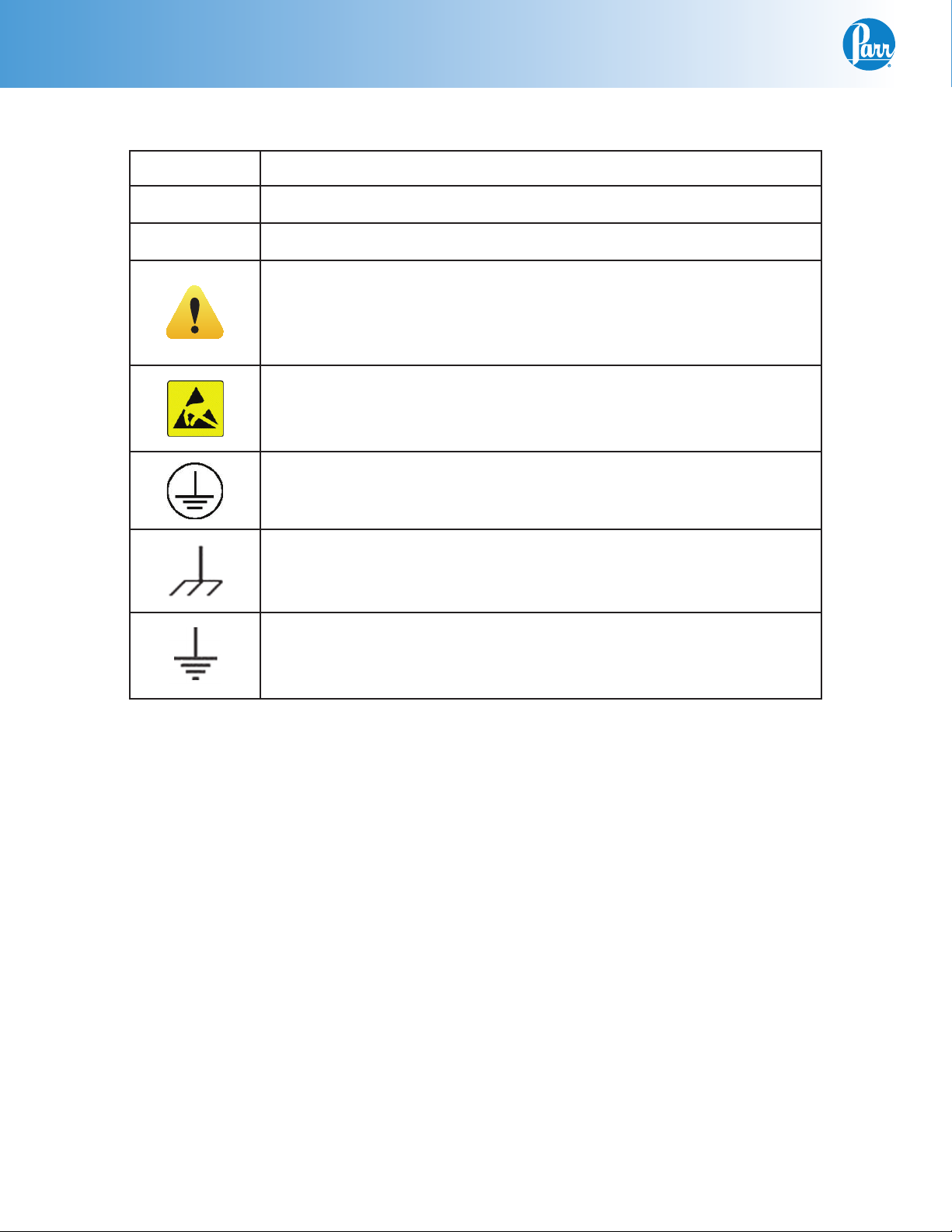
Explanation of Symbols
I On Position
O Off Position
~ Alternating Current
This CAUTION symbol may be present on the Product Instrumentation
and literature. If present on the product, the user must consult the appropriate part of the accompanying product literature for more information.
ATTENTION, Electrostatic Discharge (ESD) hazards. Observe precautions for handling electrostatic sensitive devices.
Protective Earth (PE) terminal. Provided for connection of the protective earth (green or green/yellow) supply system conductor.
Chassis Ground. Identifi es a connection to the chassis or frame of the
equipment shall be bonded to Protective Earth at the source of supply
in accordance with national and local electrical code requirements.
Earth Ground. Functional earth connection. This connection shall be
bonded to Protective earth at the source of supply in accordance with
national and local electrical code requirements.
2
Parr Instrument Company
Page 5

6755
Preface
Safety Information
To avoid electrical shock, always:
1. Use a properly grounded electrical outlet of
correct voltage and current handling capability.
2. Ensure that the equipment is connected to
electrical service according to local national
electrical codes. Failure to properly connect may
create a fi re or shock hazard.
3. For continued protection against possible
hazard, replace fuses with same type and rating
of fuse.
4. Disconnect from the power supply before
maintenance or servicing.
To avoid personal injury:
1. Do not use in the presence of fl ammable or
combustible materials; fi re or explosion may
result. This device contains components which
may ignite such material.
2. Refer servicing to qualifi ed personnel.
Intended Usage
If the instrument is used in a manner not specifi ed
by Parr Instrument Company, the protection provided by the equipment may be impaired.
General Specifi cations
Electrical Ratings
115VAC, 1.0 Amp, 50/60 Hz
230VAC, 1.0 Amp, 50/60 Hz
Before connecting the calorimeter to an electrical
outlet the user must be certain that the electrical
outlet has an earth ground connection and that the
line, load and other characteristics of the installation
do not exceed the following limits:
Voltage: Fluctuations in the line voltage should not
exceed 10% of the rated nominal voltage shown on
the data plate.
Frequency: Calorimeters can be operated from either a 50 or 60 Hertz power supply without affecting
their operation or calibration.
Environmental Conditions
This apparatus is to be used indoors.
Operating: 15 °C to 30 °C; maximum relative humidity of 80% non-condensing. Installation Category II
(overvoltage) in accordance with IEC 664.
Pollution degree 2 in accordance with IEC 664.
Altitude Limit: 2,000 meters.
Storage: -25 °C and 65 °C; 10% to 85% relative hu-
midity.
Provisions for Lifting and Carrying
Before moving the instrument, disconnect all connections from the rear of the apparatus. Lift the
instrument by grabbing underneath each corner.
Cleaning & Maintenance
Periodic cleaning may be performed on the exterior
surfaces of the instrument with a lightly dampened
cloth containing a mild soap solution. All power
should be disconnected when cleaning the instrument. There are no user serviceable parts inside the
product other than what is specifi cally called out
and discussed in this manual. Advanced troubleshooting instructions beyond the scope of this
manual can be obtained by calling Parr Instrument
Company in order to determine which part(s) may
be replaced or serviced.
Specifi cations
Probe type Thermistor
Thermometer range 10-50 °C
Resolution 0.0001 °C
Absolute accuracy
without calibration
with calibration
Repeatability,
single point +/- 0.002 °C
Linearity, 10 °C span +/- 0.002 °C
Communications port Ethernet
Data logging capacity 1MB (~10000 points)
+/- 0.100 °C
+/- 0.0500 °C
Current: The total current drawn should not exceed
the rating shown on the data plate on the calorimeter by more than 10 percent.
www.parrinst.com
3
Page 6

1
Installation
CHAPTER 1
Installation
The 6755 Solution Calorimeter requires approximately 4 square feet of work space on a
sturdy bench/table in a location free from room drafts or radiant heat sources, (preferably
in an air conditioned room providing minimal temperature change), and an electrical outlet.
Other necessary accessories include:
• Chemical balance sensitive to 0.1 mg
• Top loading balance capable of weighing up to 1.5 kg with a sensitivity of 0.1g
Unpack the calorimeter carefully and check the individual parts against the packing list. If
shipping damage is discovered, report it immediately to the delivery carrier. Handle the
glass cell, Dewar fl ask and the thermistor probe with care as these parts are fragile and
easily broken.
Set the calorimeter on a bench or table in a location that is free from drafts and protected
from sources of radiant heat. Temperature changes in the room should be minimal.
Power Connection
Plug the power line into any grounded outlet providing proper voltage that matches the
specifi cation on the nameplate of the Calorimetric Thermometer. The calorimeter will
draw approximately 100 watts of power. Grounding is very important not only as a safety
measure, but also to ensure satisfactory controller performance. If there is any question
about the reliability of the ground connection through the power cord, run a separate earth
ground wire to the controller chassis.
Turn the power switch to the on position. After a short time, the Parr logo will appear on
the LCD display followed by a running description of the instrument boot sequence. When
the boot sequence is complete, the 6772 Calorimetric Thermometer Main Menu is displayed.
Motor Installation
Remove the 493E plug with 3280HC retainer on the motor output. Attach the motor cord to
the rear of the calorimeter case using the mounting screws provided for safety purposes.
Set the cover with its attached stirring shaft onto the stainless steel air can; drop the geared
drive belt over the motor and stirrer pulleys. The drive system should run freely. Although
the belt may appear to be unusually loose, it is intended to operate under light tension to
minimize friction in the stirrer bearing. The gearing on the belt and pulleys will prevent
slippage.
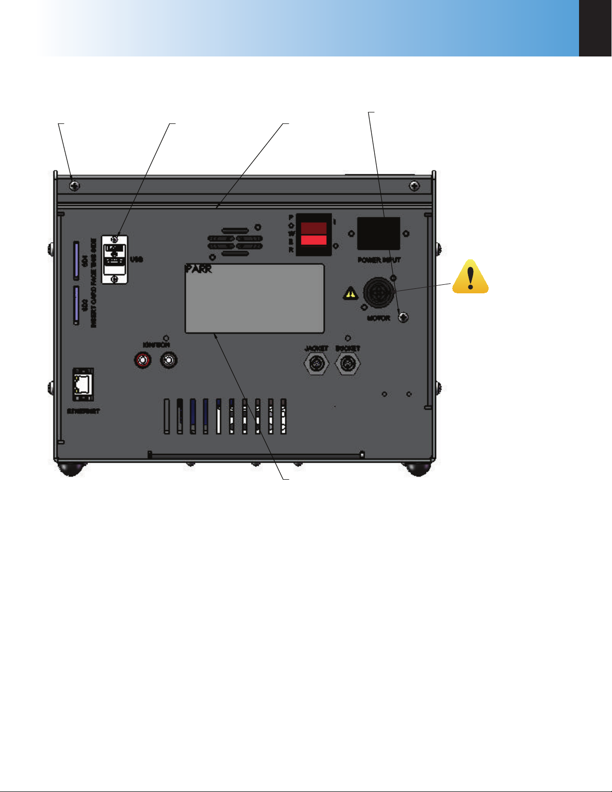
Thermistor Probe Installation
Connections for two thermistor probes are located on the back of the 6772 Calorimetric
Thermometer. If only one probe is to be used, connect it to the “bucket” connection. If the
second probe is used, it should be inserted in the hole on the left, rear of the instrument.
Install the thermistor in the cover opening and press the bushing fi rmly into place to anchor the probe in its proper position. Place the cover on the calorimeter with the orienting
pin in the alignment hole.
4
Parr Instrument Company
Page 7
6755
2X SA1332RP06
6-32 X 3/8 RHMS PHILLIPS
2X SA1140RP04
4-40 X 1/4 RHMS PHILLIPS
Figure 1
327C2
BACK PANEL (REF)
SA1332RP06
6-32 X 3/8 RHMS PHILLIPS
(SEE NOTE)
with 3280HC Retainer
installed to insulate
from live circuits when
no motor is attached.
Installation
493E Plug
1
95F
DATA LABEL
NOTE: CONNECT UNTERMINATED 493E WITH 328HC BRACKET TO THE MOTOR
OUTPUT RECEPTACLE SECURING IT USING THE SA1332RP06 FASTENER.
6772 Calorimetric Thermometer Back Panel
www.parrinst.com
5
Page 8

2
Quick Start
CHAPTER 2
Quick Start
Before starting to use the calorimeter for the fi rst time, it is recommended that the user perform a dry run with the calorimeter completely assembled, but with no liquid in the Dewar and
no sample in the rotating cell. This will give the user an opportunity to become familiar with
the individual parts of the calorimeter and the manner in which they must be handled. The
calorimeter must be standardized prior to analyzing a sample.
See Chapter 3: Operation for more detail.
1. Allow at least 20 minutes for the calorimeter to warm up.
2. Turn on the stirrer motor switch on the 6755 calorimeter.
3. Prepare and weigh the sample to 0.0001g or 1 mL in the PTFE dish.
4. Fill the Dewar volumetrically or by weight.
5. Install the thermistor probe in the cover opening and press the bushing fi rmly into place to
anchor the probe in its proper position.
6. Lower the cover assembly with the cell and thermistor probe into the Dewar and set the
cover in place on the air can, then drop the drive belt over the pulleys, start the motor and
press the start key.
7. The pre-period will now start. When the reactants come to thermal equilibrium, the thermometer will beep. Initiate the reaction by pressing downward on the push rod to drop the
sample out of the rotating cell.
8. During the reaction period, the enthalpy change will occur.
9. The calorimeter will again come to equilibrium during the post period and at the conclusion
of the test, the calorimeter will signal the user and produce a report.
10. Stop the calorimeter motor, raise the cover carefully and wipe any excess liquid from the
parts that were immersed in the Dewar. Remove the thermistor probe from the cover and
remove the sample dish from the end of the push rod; then remove the rod and release the
glass cell from the drive shaft.
11. Lift the Dewar out of the air can and empty it. Wash and dry all wetted parts carefully.
12. At the end of the testing period, press the
menu. Turn OFF the thermometer at the power switch when prompted.
6
Parr Instrument Company
key on the thermometer touch screen main
Page 9

6755
Notes
www.parrinst.com
7
Page 10
3
Operation
CHAPTER 3
Operation
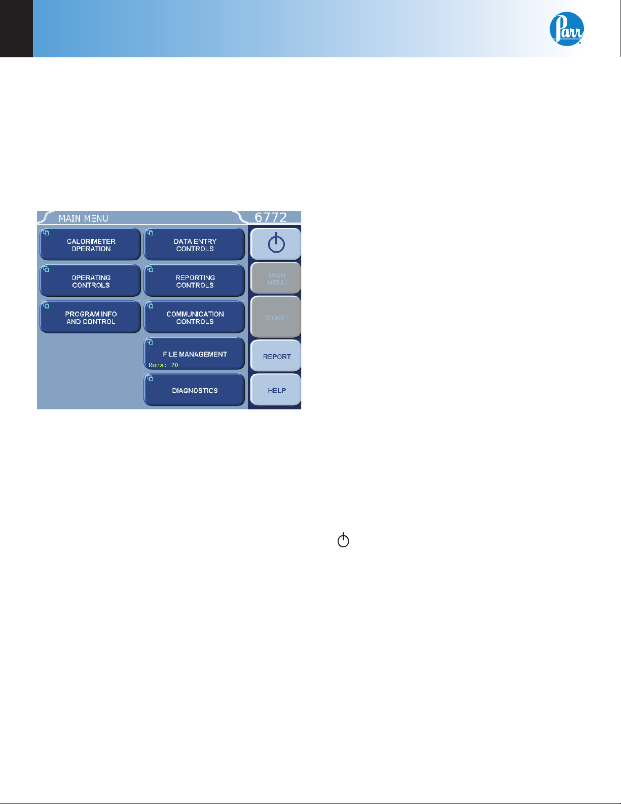
Menu System
All confi gurations and operations are handled by a
menu-driven system operated from the bright touch
screen display. The settings and controls are organized into eight main sections as displayed on the
MAIN MENU.
4. Data Displays. Most of these keys display values
that have been calculated by the Calorimetric
Thermometer and are informational only. Certain ones can be overridden by the user entering
a desired value through a sub-menu. The value
is displayed in the lower right corner of the key.
Note: Some keys will respond with an opportunity for the user to confi rm the specifi ed action
to minimize accidental disruptions to the program
and/or stored data.
Control Keys
There are fi ve control keys which always appear
in the right column of the primary displays. These
keys are unavailable when they are gray instead of
white.
1. Escape. This key is used to go up one level in
the menu structure.
2. Main Menu. This key is used to return to the
main menu touch screen from anywhere in the
menu structure.
Note: Keys with a “double box” in the upper
left hand corner lead to sub-menus.
Menu Keys
The controls that change the data fi eld information
in the menus will be one of the following:
1. Toggles. These data fi elds contain ON/OFF or
YES/NO choices. Simply touching the key on the
screen toggles the choice to the other option.
The current setting is displayed in the lower
right corner of the key.
2. Option Selection. These data fi elds contain a list
of options. Touching the key on the screen steps
the user through the available choices. The current setting is displayed in the lower right corner
of the key.
3. Value Entry Fields. These data fi elds are used
to enter data into the Calorimetric Thermometer. Touching the key on the screen brings up a
sub-menu with a key pad or similar screen for
entering the required value. Some keys lead to
multiple choices. Always clear the current value
before entering a new value. Once entered the
screen will return to the previous menu and the
new value will be displayed in the lower right
corner of the key.
3. Start. This key is used to start a Calorimetric
Thermometer test.
4. Report. This key is used to access the test re-
sults stored in the Calorimetric Thermometer, to
enter thermochemical corrections, and to initiate a report on the display, printer or attached
computer.
5. Help. This key is used to access help screens
related to the menu currently displayed on the
touch screen.
6.
This key appears in the Escape key location
when the main menu is displayed. This key is
used to shut down the calorimeter program before turning off the power.
Programming
The program in the 6772 Calorimetric Thermometer can be extensively modifi ed to tailor the unit
to a wide variety of operating conditions, reporting
units, laboratory techniques, available accessories
and communication modes. In addition, the calculations, thermochemical corrections and reporting
modes can be modifi ed to conform to a number of
standard test methods and procedures. Numerous
provisions are included to permit the use of other
reagent concentrations, techniques, combustion
aids and short cuts appropriate for the user’s work.
8
Parr Instrument Company
Page 11
6755
Operation
3
Note: Changes to the program are made by use
of the menu structure. Any of these items can
be individually entered at any time to revise the
operating program.
Default Settings
The 6772 Calorimetric Thermometer is preprogrammed with default settings for use with the 1341
Plain Jacket Calorimeter. On the operating controls
page of the 6772 Thermometer is the Method of Operation key. This key toggles the thermometer between
solution and combustion calorimetry. Make sure that
the calorimeter is set to solution calorimetry. This
will force the calorimeter to restart and bring up the
appropriate set of menus and eliminate all of the keys
dedicated to combustion calorimetry.
The default values of the 6772 are designed to operate with the 1341 Plain Jacket calorimeter. Therefore,
the following parameters must be changed in the
Calorimetry Parameters menu found in the Diagnostics Menu.
Correction (K) Parameters:
K1 0.5
K2 0.00080
K3 1.0
K4 0.0
K5 0.0
Blackout (B) Parameters:
Misfi re Blackout (B2) 72
Derivative Blackout (B3) 0.5
Dynamic Blackout (B4) 6
Equilibrium Blackout (B5) 18
Dynamic Derivative Blackout (B6) 0.02
Dynamic Time Blackout (B7) 20
Note: To perform an endothermic run, set the
Tolerance Parameter (L2) to -1.
See Chapter 14: Default Settings for a listing of the
factory default settings. A more in-depth explanation
of these parameters is found on the corresponding
parameter group help pages. These default settings
remain in effect until changed by the user. Should
the user ever wish to return to the factory default settings, go to the Program Info and Control Menu, User/
Factory Settings, touch Reload Factory Default Settings and YES. Non-volatile memory is provided to
retain any and all operator initiated program changes;
even if power is interrupted or the unit is turned off.
If the unit experiences an intentional or unintentional
“Cold Restart”, the controller will return to the last
known settings.
The default parameters of the 6772 Calorimetric
Thermometer can be changed to guarantee that the
thermometer, when cold restarted, will always be in
the desired confi guration before beginning a series
of tests. Users who wish to permanently revise their
default settings may do so using the following procedure:
• Establish the operating parameters to be stored
as the user default settings.
• Go to the Program Info and Control Menu, User/
Factory Settings, User Setup ID, and enter the
desired User Setup ID.
• Select Save User Default Settings
• To re-load the user default setting, go to the
Program Info and Control Page, User/Factory
Settings, Re-load User Default Settings, and YES.
Performing an Analysis
Tests can be run in a strictly manual fashion or automatically where the thermometer sequences the
calorimeter through the pre and post periods. The
manual sequencing approach is useful for applications where raw data is logged and subsequently
analyzed, off-line. In the automatic mode, the thermometer fully sequences the test and applies real
time corrections to the calorimeter temperature rise
in order to correct for all systemic heat leak effects.
In either case, the operator must determine the appropriate temperature source for the jacket.
• Probe – This method uses a thermistor probe
attached to the jacket wall to measure the actual
temperature of the surroundings (at the chosen
point) and the heat leak corrections are based
upon the actual differences between the bucket
and this external jacket temperature.
• Calculated – During the initial equilibrium period
this method analyzes the actual heat leak rate
and calculates the apparent temperature of the
surroundings which would generate this rate and
applies this calculated jacket temperature for the
determination.
• Fixed – In this method the operator determines
what his jacket temperature will be and enters it
into the thermometer. All heat leak corrections are
then based upon this fi xed jacket temperature.
For most applications the calculated method is recommended.
www.parrinst.com
9
Page 12

3
Operation
Sample Size
The rotating sample cell will hold up to 20 ml of
liquid sample or a solid sample weighing up to one
gram. More than one gram of solid may be used in
some cases, but smaller samples are preferred so
that the heat capacity and ionic strength of the system will not change signifi cantly when the reactants
are mixed. The Dewar must be fi lled with not less
than 90 ml and not more than 120 ml of liquid to
properly cover the rotating cell.
Filling the Dewar
It is best to lift the Dewar out of the air can during
the fi lling operation. The liquid to be placed in it
can be measured volumetrically, or the Dewar can
be placed on a solution or trip balance and fi lled by
weight. After fi lling the Dewar, set it in the air can
and gently push the spacer ring down as far as it
will go.
Loading a Solid Sample
Solid samples should be suitably ground so that
they will dissolve quickly or mix uniformly with the
liquid in the Dewar. Place the 126C PTFE Dish on
an analytical balance and weigh the sample directly
into the dish. Be careful not to drop any of the sample into the push rod socket. After the fi nal weighing, set the dish on a fl at surface and carefully press
the glass bell over the dish to assemble the cell. Do
not grasp or press the thin-walled glass stem during this operation; it is fragile and will break easily. Instead, grasp the bell and press it fi rmly onto
the dish. Then lift the cover from the calorimeter
and attach the cell to the stirring shaft by sliding
the plastic coupling onto the shaft as far as it will
go and turning the thumbscrew fi nger tight. If the
thumbscrew is not tight against the shaft, the contents will not be released. If necessary, use a 9/64
Allen wrench to tighten further. Hold the cover in
a horizontal position and lower it carefully until
the bottom of the rotating cell rests on a fi rm, fl at
surface; then insert the push rod through the pulley
hub and press the end of the rod into the socket in
the 126C Sample Dish.
Loading a Liquid Sample
Liquid samples can be measured into the rotating
cell either by volume or by weight. Best precision is
obtained by weighing, but fi lling from a volumetric
pipette may be adequate in some cases. Set the
126C PTFE Dish on a fl at surface and press the glass
bell over the dish, handling the glass carefully as
described above. If the sample is to be weighed,
tare the empty cell on a laboratory balance; insert a
pipette through the glass stem and add the liquid,
then reweigh the cell. Attach the cell to the stirring
shaft and insert the push rod.
Installing the Loaded Cover Assembly
Install the thermistor probe in the cover opening
and press the bushing fi rmly into place to anchor
the probe in its proper position. Lower the cover
assembly with the cell and thermistor probe into the
Dewar and set the cover in place on the air can, then
drop the drive belt over the pulleys and start the
motor as required.
Combining the Reactants
Each test in a solution calorimeter can be divided
into three distinct time periods:
1. A pre-period during which the reactants are allowed to come to an initial thermal equilibrium.
The thermometer will beep to inform the operator that it has established the initial equilibrium
and that it is now time to initiate the reaction.
2. A reaction period during which the reactants are
combined and an enthalpy change occurs in the
system.
3. A post-period during which the calorimeter
again comes to equilibrium. The thermometer
will produce a report when the fi nal equilibrium
has been achieved and that the test is complete.
At the end of the pre-period, start the reaction by
pressing the push rod downward to drop the sample
out of the rotating cell. This should be done quickly
without interrupting the rotation of the rod without
undue friction from the fi nger. Push the rod down
as far as it will go; after which it should continue
to rotate the pulley. Let the stirrer continue to run
during the reaction and the calorimeter reports its
results.
10
Parr Instrument Company
Page 13

6755
Operation
3
Emptying the Calorimeter
Stop the calorimeter motor, raise the cover carefully
and wipe any excess liquid from the parts that were
immersed in the Dewar. Remove the thermistor
probe from the cover and remove the sample dish
from the end of the push rod; then remove the rod
and release the glass cell from the drive shaft. Lift
the Dewar out of the air can and empty it; then wash
and dry all wetted parts carefully.
The two operating modes, (manual or automatic)
are outlined below:
Manual Test Sequencing
Some users may wish to construct their own thermo
gram and apply the classic graphical corrections developed by Dickenson and others. In this case, the
actual temperatures can be logged to the memory
of the thermometer and then analyzed at the end of
the test. These logged temperatures can be printed
on an attached printer or transferred to a computer
using an SD Card. The Ethernet Connection can also
be used to transfer temperatures to a computer for
plotting.
First, select the appropriate jacket temperature
source as described previously. Then fi ll the Dewar.
Next, prepare and load the reaction. After the calorimeter is fully assembled, turn on the motor, and
then turn on the stirrer by pressing the stirrer key on
the calorimeter operation menu screen. Turn on the
data logger (accessed via the Diagnostics page) in
order to periodically record the bucket or calorimeter temperature. The bucket temperature is updated
every 10 seconds. Turn on the calorimetric preperiod. The pre-period should last for 6-7 minutes.
After the 6-7 minute pre-period test phase, start the
reaction by pressing the push rod downward to
drop the sample out of the rotating cell. This begins the reaction and subsequent post-period. The
calorimeter temperature should begin to signifi cantly change at this point, indicating sample reaction. The calorimetric post-period should last for an
additional 6-7 minutes from sample introduction. At
the conclusion of the post-period, turn the stirrer off
by pressing the stirrer key once again. The motor
switch may be left in the “on” position for subsequent tests. Empty and clean the calorimeter.
If the data log destination is a log fi le, the log fi le is
located at /fl ash/log/datalog.csv and may be retrieved via FTP. The log fi le is easily imported into a
spreadsheet program where the calorimeter temperature can be plotted in order to realize a thermal
curve. Instructions for working with or analyzing
thermal curves are found in the calculations section.
Automatic Test Sequencing
The solution calorimeter will perform all calculations for the user. To do this, fi rst select the appropriate jacket temperature source. For most
applications, the calculated jacket approach works
well. First, select the appropriate jacket temperature
source as described previously. Then fi ll the Dewar.
Next, prepare and load the reaction. After the calorimeter is fully assembled, turn on the motor, and
then press the START key located on the right hand
side of the screen. This will activate the stirrer that
gently circulates the fl uid that surrounds the glass
cell. The thermometer will prompt for the sample
ID number. This begins the calorimetric pre-period.
After the thermometer determines that adequate
temperature equilibrium is realized, the thermometer will prompt the user to start the reaction by
pressing the push rod downward to drop the sample
out of the rotating cell. This starts the calorimetric
post-period. The calorimeter temperature should
begin to signifi cantly change at this point, indicating
sample reaction. The calorimetric post-period will
last for an additional 6-7 minutes until the calorimeter temperature drift rate suffi ciently stabilizes. At
the end of the post-period the calorimeter will signal
the end of the test and generate a report.
Stop the calorimeter motor, raise the cover carefully
and wipe any excess liquid from the parts that were
immersed in the Dewar. Remove the thermistor
probe from the cover and remove the sample dish
from the end of the push rod; then remove the rod
and release the glass cell from the drive shaft. Lift
the Dewar out of the air can and empty it; then wash
and dry all wetted parts carefully.
www.parrinst.com
11
Page 14
4
Menu Descriptions
CHAPTER 4
Menu Descriptions
Note: Keys which make global changes to the
setup of the calorimeter contain a YES or NO
response to make certain that the user wishes
to proceed. This two step entry is intended to
prevent inadvertent global program changes.
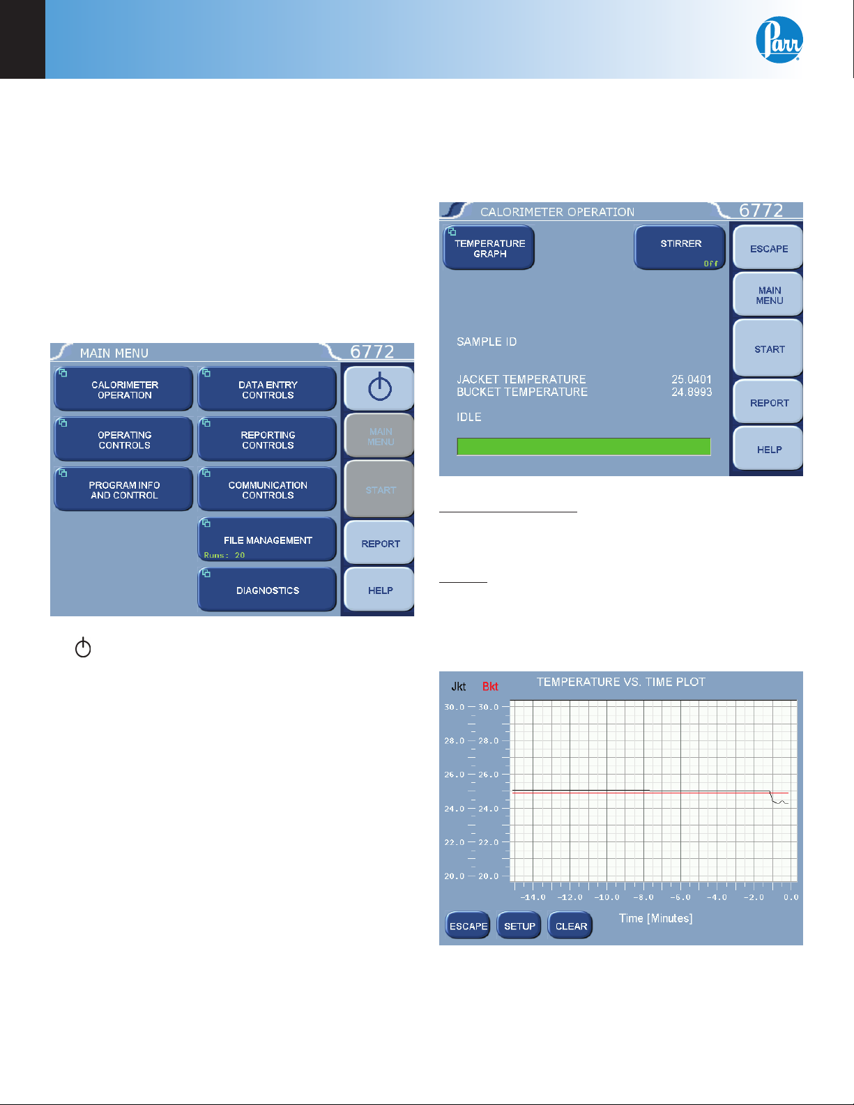
Main Menu
Selecting the Main Menu key on any menu will return you to the screen pictured below.
Calorimeter Operation Menu
The Calorimetric Thermometer will normally be
operated from the Calorimeter Operation Menu,
although tests can always be started from any menu
screen.
1. : This key appears in the Escape key loca-
tion when the main menu is displayed. This key
is used to shut down the calorimeter program
before turning off the power.
2. Start Key: Press the Start key to begin an Auto-
matic Test.
3. Report: Press the Report key to begin the report-
ing process.
4. Help: Press the Help key on any screen to dis-
play the explanation text for that screen.
Temperature Graph: Press this key to display a realtime plot of the bucket and/or jacket temperature on
the Temperature vs. Time Plot screen.
Stirrer: Toggles ON/OFF. This key provides a convenient way to manually start and stop the calorimeter
stirrer motor. The motor must be physically turned
on for this function to be active.
Temperature vs. Time Plot
12
Press the Setup key to access the Temperature Plot
Setup Menu, which has many keys that permit the
user to fully customize both the x (time) axis and the
scaling of the y axis.
Parr Instrument Company
Page 15
6755
Menu Descriptions
4
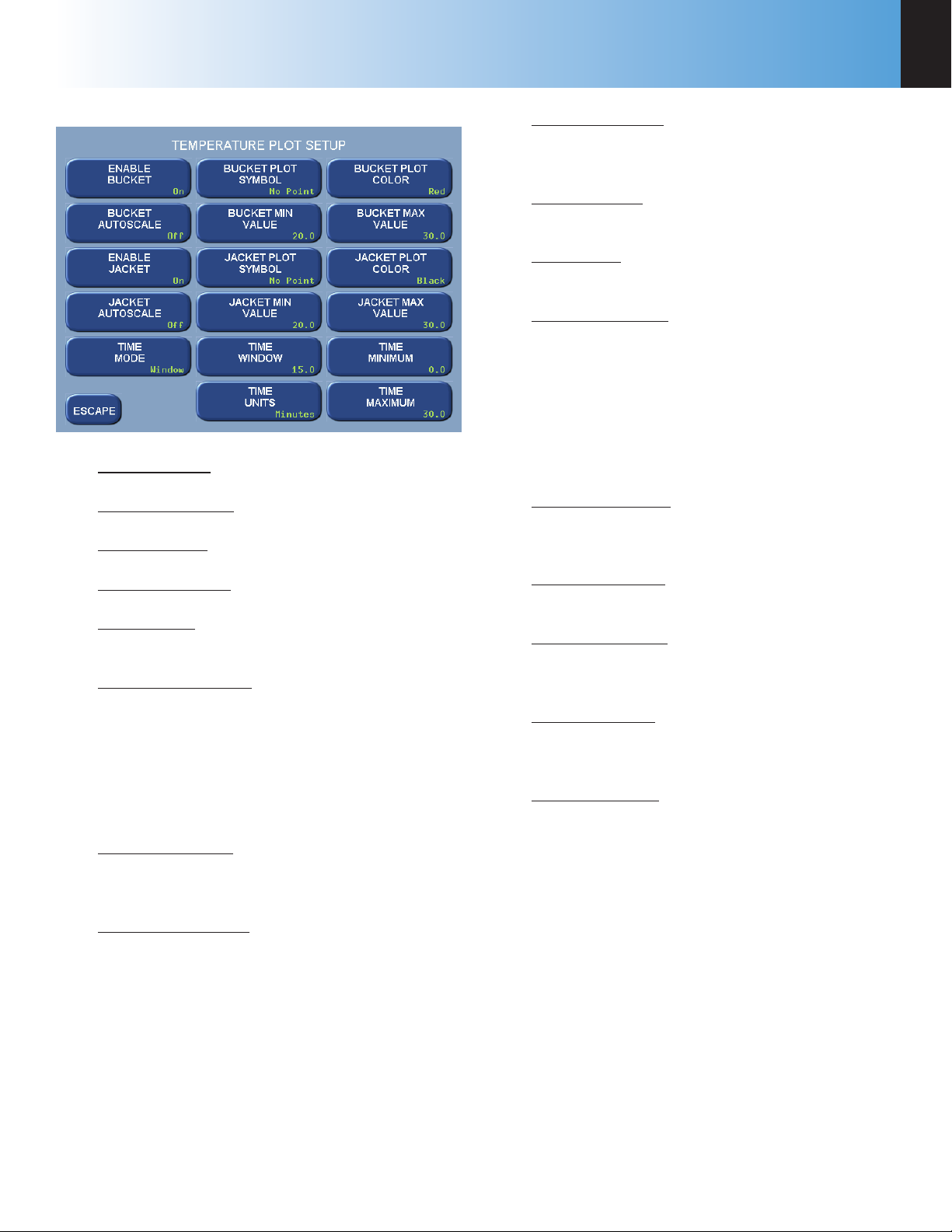
Temperature Plot Setup Menu
Enable Bucket: Toggles ON/OFF.
Bucket Autoscale: Toggles ON/OFF.
Enable Jacket: Toggles ON/OFF.
Jacket Min Value: Press this key to access its
numeric dialog box to set a minimum jacket
value.
Time Window: Sets the time scale for the Xaxis.
Time Units: Toggles between minutes and
seconds.
Bucket Plot Color: Toggles between:
» Red
» Green
» Yellow
» Blue
» Magenta
» Cyan
» White
» Black
Bucket Max Value: Press this key to access its
numeric dialog box to set a maximum bucket
value.
Jacket Autoscale: Toggles ON/OFF.
Time Mode: Toggles between Autoscale, Win-
dow, and Range.
Bucket Plot Symbol: Toggles between:
» No Point
» Small Dot
» Round
» Square
» Up Triangle
» Down Triangle
» Diamond
Bucket Min Value: Press this key to access its
numeric dialog box to set a minimum bucket
value.
Jacket Plot Symbol: Toggles between (same as
Bucket Plot Symbol, above).
Jacket Plot Color: Toggles between (same as
Bucket Plot Color, above).
Jacket Max Value: Press this key to access its
numeric dialog box to set a maximum jacket
value.
Time Minimum: Press this key to access its
numeric dialog box to set the least amount of
time for the run.
Time Maximum: Press this key to access its
numeric dialog box to set the greatest amount
of time for the run.
www.parrinst.com
13
Page 16
4
Menu Descriptions
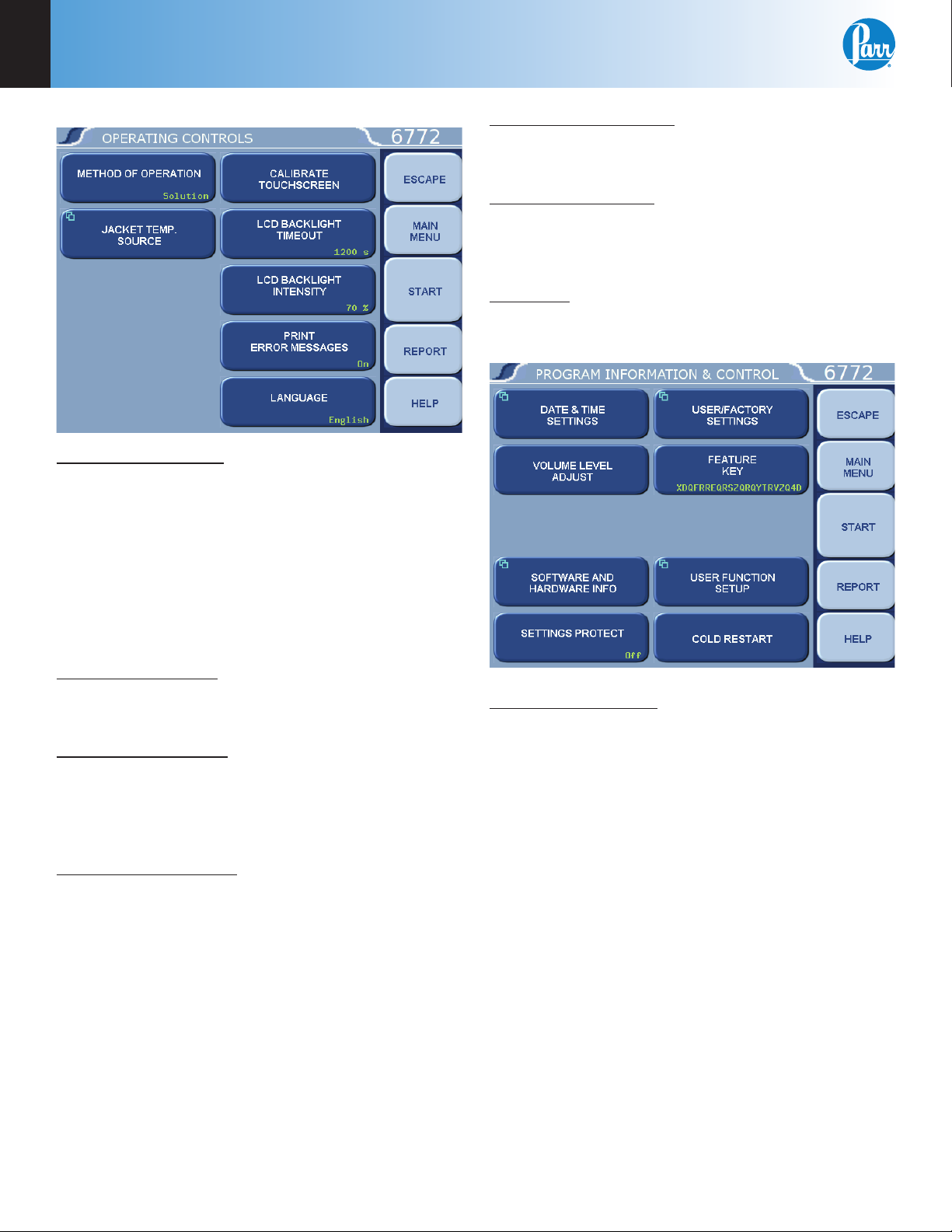
Operating Controls Menu
Method of Operation: Offers an operating mode
of either combustion or solution. In the solution
calorimetry mode, the instrument menu structure is
streamlined in order to remove items that are only
relevant to solution calorimetry. The text on the key
displays the current instrument operating mode.
Pressing the key will prompt the user to restart the
calorimeter, loading the appropriate menu structure.
Help screens are context sensitive with respect to
the operating mode.
LCD Backlight Intensity: This key accesses a submenu with a slide control which adjusts the brightness on the LCD display for optimum viewing.
Print Error Messages: When turned ON, all error
messages will be printed on the printer as well as
displayed on the screen. When turned OFF, messages will only display on the screen.
Language: Steps the Calorimetric Thermometer
through the installed operating languages.
Program Information and Control Menu
Jacket Temp. Source: Press this key to display a
menu that allows the user to select the source for
the jacket temperature used for tests.
Calibrate Touchscreen: This key prompts the user
to touch the screen at predefi ned points in order to
facilitate touch screen calibration. It is important that
a touch screen stylus, rather than a fi nger, be used
in order to realize an accurate calibration.
LCD Backlight Timeout: The unit is equipped with
an automatic circuit to shut off the backlight when it
is not being used. The back light will shut off if there
is no keyboard activity for the number of seconds
entered. Pressing any key will automatically turn
the back lighting ON. A setting of 0 will keep the
backlight ON at all times.
Date & Time Settings: Access the sub-menu on
which Date & Time are set.
14
Parr Instrument Company
Page 17

6755
Menu Descriptions
4
Date & Time Settings
Date: Displays current date and accesses the
sub-menu on which the date is set (YY/MM/
DD) format.
Time: Display current time and accesses the
sub-menu on which time is set in (HH:MM)
format.
Time zone: Allows the user to select the local
time zone. Pressing the button will toggle
through the time zones.
Volume Level Adjust: Displays a slider adjustment
to change the volume of calorimeter.
Software and Hardware Info: This screen displays
important information such as the main software
version, I/O board hardware information, CPU type,
I/O fi rmware revision, and Controller IP address.
User/Factory Settings
Reload Factory Default Settings: Used to erase
all of the settings and restore the factory default settings.
Reload User Default Settings: Used to restore
current user setup ID settings should the program in the instrument be corrupted for any
reason.
Save User Default Settings: Used to record the
setup to the memory once the user has confi gured the instrument to their operating requirements.
Note: Keys which make global changes to the setup of the calorimeter contain a YES or NO response
to make certain that the user wishes to proceed.
This two step entry is intended to prevent inadvertent global program changes.
Settings Protect: Provides protection for the program options and settings on the menus. If this is
turned ON, the user will be warned that enumeration keys are locked when a key is pressed. Enumeration Keys either toggle a value (ON/OFF) or select
from a predefi ned list. This feature is used primarily
to protect the instrument settings from accidental
changes if one were to inadvertently touch or bump
up against the touch screen.
User/Factory Settings: This key leads to a sub-menu
that allows the user to save or recall user defi ned instrument settings. Additionally, factory pre installed
settings supporting different bombs or special operating modes can also be recalled.
Compare Settings With Factory Defaults: This
button will bring up a screen that will show the
differences in the current settings of the calorimeter with the factory defaults.
Feature Key: Unique Feature Keys obtained from
Parr allow the user to access capabilities on the
instrument such as bar code interfacing or remote
operation of the calorimeter.
User Function Setup: This key leads to sub menus
that support the confi guration of fi ve factory/user
defi nable function keys. The function keys are accessible from the Diagnostics page.
Cold Restart: This is essentially the same as cycling
power on the unit. All valid test data will be retained
during this cold restart procedure.
www.parrinst.com
15
Page 18

4
Auto Sample ID Controls
Menu Descriptions
Data Entry Controls Menu
Auto Sample ID Controls: Accesses sub-menu for
controlling the automatic assignment of sample
identifi cation numbers.
Auto Sample ID Controls
Next Auto Sample ID Number: Establishes the
initial sample number for a series of tests and
then shows the next sample ID which will be
assigned. Used when the Automatic Sample
ID is set to ON. Press this key to access a submenu for entering a numeric increment.
Auto Sample ID Increment: Establishes the increment between sample numbers; used when
the Automatic Sample ID is set to ON. Press
this key to access a sub-menu for entering a
numeric increment.
Reporting Controls Menu
Automatic Sample ID: When set to ON the unit
will automatically assign sample identifi cation
numbers in accordance with parameters set by
the other three keys on this menu. When set
to OFF, the user manually enters each sample
ID when prompted to do so.
Auto Sample ID Prefi x: An entry here will be
used as a prefi x for all sample IDs, if the Automatic Sample ID is set to ON. Press this key
to access a sub-menu for entering an alphanumeric prefi x.
Report Width: Toggle this key to set the column
width of the printer to either 40 or 80 columns. Select 40 when the 1758 Printer is used.
Automatic Reporting: Toggles the automatic reporting ON/OFF. When ON, reports will be generated at
the conclusion of the test. When OFF, reports will
only be generated through the Report Menu.
Automatic Report Destination: Toggles to direct the
reports to the Printer port or the screen display.
Individual Printed Reports: When set to ON, will
generate extra line feeds for each report printed. In
the OFF position, only one header will be printed for
a series of tests.
16
Parr Instrument Company
Page 19

6755
Menu Descriptions
4
Communication Controls Menu
Accesses sub-menus which set the communications
protocols for the printer and balances.
Printer Type: Toggles between a Parr 1758 and a generic printer. When set for the 1758 Printer, all of the
features of this printer, such as bold printing, will be
activated.
Balance Port: Accesses sub-menu, Balance Port
Communications.
Balance Port Communications
Balance Type: Toggles through the available
balance templates.
Balance Port Device: This key displays a screen
which allows the user to specify the balance
port device. The default (dev/ttyUSB0) is the
designation for the fi rst USB to serial converter
cable assigned by the calorimeter upon power
up.
Customize Balance Settings: Sets the communication parameters for the USB port used
for the balance port. Standard options for
data bits, parity, stop bits, handshaking, baud
rate and balance type are provided to match
any devices that might be connected to these
ports.
www.parrinst.com
17
Page 20

4
Menu Descriptions
Balance Port Settings
» Number of Data Bits. Standard options
for data bits. Toggles between 7 and 8.
» Parity. Standard options for parity.
Choose from None, Odd or Even.
» Number of Stop Bits. Standard options
for stop bits. Toggles between 1 and 2.
» Handshaking. Standard options for hand-
shaking. Choose from Xon / Xoff, RTS/
CTS and None.
» Baud Rate. Standard options for baud
rate. Choose from 19.2K , 9600, 4800,
2400, 1800, 1200, 600, 300, 150, 134.5,
110, and 75.
» Data Precision. This key allows the user to
establish the number of digits to the right
of the decimal point that are passed from
the balance handler.
» Transfer Timeout (seconds). This value
determines how long the interface will
wait before giving up on a weight transfer. The value is entered in seconds.
» Balance Handler Strings. This key leads to
a submenu that allows balance template
to be customized for unique balances or
needs.
Log Balance to Display: Directs the incoming data
stream from the balance to a display buffer. This
function can be used to determine the data format
from an unknown balance type. The display buffer is 40 characters in length. The balance must
be forced to issue at least 40 characters before the
contents of the buffer are displayed.
Balance Port LoopBack Test: Initiates a loopback test
on the port. A special loopback plug is required in
order to perform this test.
Further information on establishing communications for the Printer, Balance, Network
Interface, Bar Code Port and other Network
Data Devices can be found in the Accessory
Connections section of this manual.
18
» Data Characters from Balance. This
setting is only used when the generic
balance format is selected. This value
determines the number of numeric data
characters (0-9 . + -) to accept. Any additional characters after this value and
before the string terminating <CR> are
discarded.
Parr Instrument Company
Page 21

6755
Menu Descriptions
4
File Management Menu
Run Data File Manager: This key activates the File
Manager. The File Manager is used to delete or
rename test report fi les. It is also used to convert fi le
types.
Run Data File Manager
» Select: This key is used to begin the fi le
selection process. The up / down and
page up / page down keys are used to
scroll up and down the fi le list. Pressing
the select key when a fi le is highlighted
blue will highlight the fi le with a cyan
color. This indicates that it is selected.
Multiple fi les throughout the list can be
selected in this fashion.
» Extend Sel: This key selects all fi les
between the last fi le selected and the fi le
that is highlighted in blue.
» Desel All: This key deselects all fi les pre-
viously selected.
» Rename: This key allows the user to re-
name the blue highlighted fi lename.
» Delete: This key deletes all selected fi les.
Format the SD Card: This key provides access to a
function that will format the user installed SD card
in a manner that is compatible with the CPU Boot
loader. Formatting the card this way is recommended prior to installing any program update fi les on
the SD card.
Run Data File Manager: The white upper
portion of the Run Data File Manager screen
presents all tests in memory in a scrollable
window. Test attributes include fi lename
(sample ID), test type, status, and date. Touching anywhere in the column related to a given
test attribute will sort the fi le list by that attribute. Successive touches will toggle between
an ascending and descending sort.
Formatting will erase all fi les on the card!
SD Card capacity is limited to 2GB.
SDHC cards will not work.
Copy Run Data to SD Card: This key copies all test
data to a SD memory card inserted into the rear of
the calorimeter controller. This feature is used as a
means of either archiving data or transferring it to a
PC.
Copy User Settings to SD Card: This key copies all
previously saved user setups to the SD.
Copy User Settings From SD Card: This key copies
all user setups previously saved to SD back to the
calorimeter controller memory. This feature can be
used to confi gure multiple calorimeters in an identical manner.
www.parrinst.com
19
Page 22

4
Menu Descriptions
Diagnostics Menu
Provides the user with the means to test many of
the components and subsystems of the Calorimetric
Thermometer. These capabilities should be used in
conjunction with the Maintenance Instructions in
order to obtain the maximum benefi ts from these
capabilities.
Calorimetry Parameters: This key accesses its submenu which allows access to the calorimetry parameters used to automatically sequence a calorimetric
test. These parameters are organized according to
their use. The three types are:
• Tolerance (L) Parameters. These parameters
are used primarily to establish appropriate
criteria for transitioning from pre-period to
post-period as well as ending a test.
Data Logger Controls
Data Logger: This key toggles the data logging
function ON/OFF.
Data Log Interval: This key displays the interval of which the selected data is logged. The
interval in seconds is defi ned in the Select
Data Items sub-menu (normally 10 seconds).
This roughly matches the update interval for
the bucket temperature.
Data Log Destination: Options are logfi le,
printer or both. When the logfi le option is
selected, the logfi le is located at /fl ash/datalog.
csv. The maximum allowed size for this fi le is
roughly one megabyte. If the fi le reaches this
size, logging is halted.
• Correction (K) Parameters. These parameter s
are used for calorimeter temperature drift
corrections.
• Blackout (B) Parameters. These parameters
establish suitable blackout criteria for the
post-period of the testing sequence.
Test Ignition Circuit: Activates the ignition circuit.
A volt meter can be placed across the fi ring connections to ensure that the actual fi ring charge is reaching these contacts.
Note: The ignition Unit circuit is not used in the
6755 Solution Calorimeter.
Data Logger: Displays ON/OFF status and accesses
the Data Logger Controls Menu for setting the specifi c logging controls.
20
Parr Instrument Company
Select Data Log Items: Press this key to access
the Data Log Items sub-menu, which provides
keys for fi fteen items that can be individually selected for logging. By default, both the
bucket and jacket temperatures are logged. All
records are date and time stamped. The most
commonly helpful items to log are:
» D0 - Corrected calorimeter drift rate.
» Tsum - Accumulated temperature rise.
» T1 - Extrapolated temperature rise.
» C0 - Temperature conversion counter
Page 23

6755
Menu Descriptions
4
Data Log Format: Toggles between Text Format
and Data Format (csv). Data is either logged
with the supporting tag information (text) or in
a comma separated variable (csv) data format
as selected by the user. The text setting is useful if the data log destination is a printer. The
data (csv) format is especially useful if the data
is ultimately transferred to another computer
for post processing, graphing etc. The log fi le
can be transferred to another computer via
FTP or SD Card.
Delete Data Log File: When this key is pressed
the contents of the data log fi le are deleted.
Log Trigger: Select when the log fi le data
is recorded. Timebase will record the data
according to the Data Log Interval. Bucket
Conversion records the data when the bucket
temperature is updated.
View System Log: This key accesses its sub-menu
which displays the contents of /fl ash/log/messages.
This fi le is used primarily to log application program
debug messages. Press the Print key to print these
messages.
User Defi ned Functions: This key leads to a submenu that offers fi ve special purpose user/ factory
defi nable function keys.
Combine Determination Reports: Pressing this
key combines all determination reports into a
single fi le named /tmp/bigdetfi le.txt.
Combine Standardization Reports: Pressing
this key combines all standardization reports
into a single fi le named /tmp/bigstdfi le.txt.
Instrument Monitor: This key accesses its sub-menu
screen which provides a summary of most of the
important instrument parameters. This screen is
used to detail the course of a test or to observe the
heating / cooling performance of the calorimeter.
View System Info: Press this key to display a screen
with current operating system information / statistics such as:
• Processes and their associated PIDs
• Memory
• Mass Storage
• Network
Press the Print key to print this information.
View Instrument Log: Press this key to display a
screen with contents of the /tmp/instlog fi le. It contains a sequential log of the instrument’s processing. Press the Print key to print this log.
I/O Diagnostics: Press this key to display its I/O
Diagnostics sub-menu, which allows the user to manipulate digital outputs for troubleshooting. The I/O
Diagnostics screen is used to display the digital outputs at a basic level for troubleshooting. Both the
bucket and jacket temperatures are also displayed
on this screen. Any output can be selected using
the left and right arrow keys. The selected output is
turned ON (1) or OFF (0) using the 1 and 0 keys. Prior to entering the Diagnostics Menu, the controller
stores the present state of the outputs. This state is
restored when you exit this screen. Digital outputs
cannot be manipulated while a test is in progress.
I/O Diagnostics
Note: Combined Determination Reports and
Combined Standardization Reports are not
applicable for Solution Calorimetry.
Logged Data to SD: Copies the internal data
log fi le to an SD card inserted into the back of
the calorimeter.
www.parrinst.com
21
Page 24

5
Calculations
CHAPTER 5
Calculations
Standardization
A sample of tris (hydroxymethyl) aminomethane,
commonly called TRIS, is furnished with the 6755
Calorimeter to provide a reliable standardizing reagent. TRIS is furnished as a dry powder which can
be used directly from the bottle as supplied without
further preparation, but undue exposure to air and
moisture should be avoided in order to preserve the
integrity of the standard.
For standardizing the 6755 Solution Calorimeter,
solid TRIS can be dissolved in dilute hydrochloric
acid in a controlled reaction for which the amount of
heat evolved is well established. In the recommended standardization procedure described below, 0.5
gram of TRIS is dissolved in 100 ml of 0.1 N HCl to
evolve 58.738 calories per gram of TRIS AT 25 °C.
1. Tare the Dewar on a solution or trip balance and
add exactly 100.00 + .05 grams of 0.100 N HCl.
2. Weigh 0.50 +.01 gram of TRIS into the 126C Teflon Dish on an analytical balance to an accuracy
of +.0001 g.
Calculate the energy equivalent of the calorimeter
and its contents by substituting in the equation:
where:
e is expressed in calories per °C.
Determine the energy equivalent of the empty calorimeter by subtracting the heat capacity of the 100 g
of 0.1N HCl from e, as follows:
=
e’
where:
e’
100.00
0.99894
Example:
A standardization reaction involving 0.5017
grams of TRIS, and 100.00 grams of 0.100N HCl
producing a net corrected temperature rise of
∆TC = 0.244 °C with 0.63 rise, T(0.63R), at 24.301
°C.
e - (100.00)(0.99894)
=
energy equivalent of the empty
calorimeter in calories per °C.
=
mass of 0.100N HCl in grams
=
specifi c heat of 0.1N HCl at 25 °C
3. Assemble the rotating cell; place it in the calorimeter and start the motor.
4. Let the calorimeter come to equilibrium; then
initiate the reaction by depressing the push rod.
5. Analyze the thermogram to determine the net
corrected temperature rise, ∆T
sion of the test the instrument will report a net
corrected temperature rise, ∆Tc.
6. Calculate the known energy input by substituting in the equation:
QE = m[58.738 + 0.3433(25 - T(0.63R))]
where:
QE = the energy input in calories
m = weight of TRIS in grams
T(0.63) = temperature at point 0.63R on the
thermogram
Note: The term, 0.3433(25 – T(0.63R)), adjusts
the heat of reaction to any temperature above
or below the 25 °C reference temperature.
. At the conclu-
c
In this reaction the known energy input is:
QE = 0.5017 [58.738+0.3433 (25 - 24.301)]
= 29.589 calories
The energy equivalent, e, of the calorimeter and
its contents is then computed:
The energy equivalent, e’, of the empty calorimeter is then computed:
22
Parr Instrument Company
Page 25

6755
Calculations
5
Calculating the Energy Change
The energy change, Q, measured in this calorimeter
is calculated by multiplying the net corrected temperature change, ∆Tc, by the energy equivalent, e, of
the calorimeter and its contents.
Q = (∆Tc)(e)
If ∆Tc is measured in °C and e is expressed in calories per °C, Q will be reported in calories. (The
energy equivalent, e, is determined by a standardization procedure).
The change in enthalpy, ∆H, at the mean reaction
temperature is equal to -Q divided by the amount of
sample used in the experiment, expressed either in
moles or grams.
where:
T is the temperature at the 0.63R point on the
thermogram.
Enthalpy values are usually expressed in kilocalories
per mole.
Procedures for converting enthalpy changes, ∆H, to
thermodynamic standard conditions and for using
∆H in other computations can be obtained from
thermodynamics or thermochemistry textbooks, or
from literature references.
Reading the Thermogram
In order to determine the net temperature change
produced by the reaction, it is necessary to interpolate a point on the thermogram at which the temperature reached 63 percent of its total rise. This can
be done easily by following Figure 2, although other
variations of this method can be used as well.
1. Place a straight edge over the preperiod drift line
and extend this line well past the point at which
the reaction was initiated.
2. Move the straight edge to the postperiod drift
line and extrapolate this line backward to the
mixing time. If there are fl uctuations in the
drift lines due to noise or other variations in the
signal, use the best average when drawing these
extrapolations.
3. Using a centimeter scale, measure the vertical
distance, R, between the two extrapolated lines
at a point near the middle of the reaction period.
4. Multiply the distance, R, by 0.63.
5. Set the zero end of the centimeter scale on the
extrapolated preperiod drift line and move the
scale along this line to locate a vertical intercept
with the thermogram which is exactly 0.63R
above the preperiod drift line. Draw a vertical
line through this point to intercept both drift
lines.
6. Read the initial temperature, and the fi nal temperature, at the points of intersection with the
drift lines and subtract to determine the corrected temperature rise, ∆T (see Figure 2)
∆T
= Tf - T
c
i
Figure 2
Thermogram
www.parrinst.com
23
Page 26

5
Calculations
Example - Exothermic Reaction
Problem: Determine the change in enthalpy for
solid sodium sulfate, Na
a 5 gram/liter aqueous solution of barium chloride, BaCl
Na
Ba
Corrected temperature rise
∆T
T(0.63R) = 24.885 °C
Energy equivalent
e = 121.46 cal/°C
Energy evolved
Q = (∆T
• 2H2O.
2
m
2SO4
++
solution
C
= (0.042) (121.46)
= 5.1013 calories
=
=
= 0.042 °C (from Figure 3)
) (e)
C
0.1458 grams
100.00 grams
, when dissolved in
2SO4
Enthalpy change
=
=
= -34.99 cal/g @ 24.885 °C
Or, multiplying by 142.04 (the molecular weight
of Na
)
2SO4
= (-34.99) (142.04)
= -4.970 Kcal/mole @ 24.885 °C
0.1458 g solid Na
100.00 g of 5 g/l aqueous
BaCl
• 2H2O
2
Temperature at
time of mixing
R = ∆T
0.63R 0.026 °C
T
T(0.63R) = T
T
C
i
+ 0.63R 24.885 °C
i
= Ti + R 24.901 °C
f
dissolved in
2SO4
24.852 °C
0.042 °C
24.859 °C
Figure 3
24
Exothermic Reaction
Parr Instrument Company
Page 27

6755
Calculations
5
Example - Endothermic Reaction
Problem: Determine the heat of solution of solid
potassium nitrate, KNO3, when dissolved in
water.
m
KNO
3
Distilled water
Corrected temperature rise
∆T
C
T(0.63R) = 25.400 °C
Energy equivalent
e = 121.46 cal/°C
Energy evolved
Q =
= (-0.508) (121.46)
= -61.70 calories
= -0.508 °C (from Figure 3)
(∆T
) (e)
C
0.7180 gram
=
=
100.00 grams
Enthalpy change
=
=
= -34.99 cal/g @ 24.885 °C
Or, multiplying by the molecular weight of KNO3
= (85.94) (101.10)
= 8.69 Kcal/mole @ 25.400 °C
Figure 4
0.7180g solid KNO
100.00g of distilled water
Temperature at
time of mixing
R = ∆T
0.63R -0.320 °C
T
T(0.63R) = T
T
C
i
+ 0.63R 25.400 °C
i
= Ti + R 25.212 °C
f
dissolved in
3
25.714 °C
-0.508 °C
25.720 °C
Endothermic Reaction
www.parrinst.com
25
Page 28

6
Reports
CHAPTER 6
Reports
The 6772 Calorimetric Thermometer can transmit its stored test
data in either of two ways. The
Auto Report Destination key on the
Reporting Controls Menu toggles
the report destination between
the display and an optional printer
connected to the USB printer port
of the Calorimetric Thermometer.
Test results are stored as fi les using the sample ID number as the
fi le name. A listing of the stored
results is accessed by pressing
the REPORT command key. The
REPORT command key brings up
a sub-menu on which the operator
specifi es.
Select From List: This key displays
the stored results specifi ed with
the following two keys.
Run Data Status: This key enables the operator to display fi ve report options:
• only preliminary and fi nal reports
• only fi nal reports
• only preliminary reports
• only pre-weighed sample reports
• all stored reports.
The displayed fi les can be sorted by fi lename (sample ID number), by type, by status or
by date of test by simply touching the appropriate column. Individual fi les can be chosen by highlighting them using the up and down arrow keys to move the cursor. Press
the SELECT key to actually enter the selection. Once selected the highlight will turn from
dark blue to light blue. A series of tests can be selected by scrolling through the list and
selecting individual fi les. The double up and down keys will jump the cursor to the top or
bottom of the current display. If a range of tests is to be selected, select the fi rst test in the
series, scroll the selection bar to the last test in the series and press EXTEND SEL to select
the series.
26
The DESEL ALL key is used to cancel the current selection of fi les.
To bring the selected report or series of report to the display, press the DISPLAY key. To
send the reports to the printer press the PRINT key.
Parr Instrument Company
Page 29

6755
The 6772 Calorimetric
Thermometer will hold data
for 1000 tests in its memory.
These tests may be pre
weights, preliminary or fi nal
reports for either calibration
or determination runs. Once
the memory of the controller
is fi lled, the controller will
not start a new analysis until
the user clears some of the
memory.
The FILE MANAGEMENT key
on the main menu leads to
the fi le management submenu. The RUN DATA FILE
MANAGER key leads to a
listing of the fi les. Single fi les
can be deleted by highlighting
the fi le and pressing the DELETE key. The controller will then ask the user to confi rm that
this fi le is to be deleted. A series of fi les can be deleted by selecting the fi rst fi le in the
series and then the last fi le in the series using the EXTEND SEL key and then pressing the
DELETE key.
CHAPTER 7
Memory Management
Memory Management
7
The controller of the 6772 Calorimetric Thermometer can accept SD memory cards.
These cards can be used to:
• Copy test fi le data for transfer to a computer
• Copy user settings for back up
• Reload user settings to the controller to restore or update the controller’s
operating system.
• Copy the data log fi le for transfer to a computer.
SD memory cards are inserted into the slot on the back of the control section of the
Calorimetric Thermometer. Keys are provided on the FILE MANAGEMENT sub-menu
to initiate some of these functions. The data log is transferred from the User Defi ned
Functions Menu on the Diagnostics Menu.
www.parrinst.com
27
Page 30

Accessory Connections
8
CHAPTER 8
Accessory Connections
Communication Connection
There is a USB connection on the rear of the 6772 to
facilitate printer and balance connections.
The 6772 will allow the user to specify the IP addresses of one or more Balance Interface devices on
the network by selecting the Network Data Device
menu in the Communications Controls menu. Balance Interface devices are polled from device 1 to 15
for sample and / or spike weights when the weight
entry mode is set to Network.
Printer Connections
The printer type setting is on the Communication
Controls Menu. The default parameters for the 6772
Calorimetric Thermometer are set up for use with
the Parr 1758 Printer.
Balance Connections
The 6772 Calorimetric Thermometer supports input
from the multiple balance types. Additionally, a
generic input driver is provided for communications
with balances that do not conform to the supported
protocols. A new feature supported by all balance
input drivers is the ability to change the expected
number of characters in the data fi eld. The number
of data characters, indicated for each of the drivers below, are default values. This feature virtually
eliminates the need for balance input drivers to be
re-written in the event the balance manufacturer
elects to alter the output string of a balance when
new models are introduced.
The format of an unknown balance can be determined by logging the balance output to the printer
attached to the Calorimetric Thermometer. Those
protocols which send a command string to the balance will do so while logging is active. In order for
the logging to produce meaningful results, the cable
connecting the balance to the balance input port
of the Calorimetric Thermometer must be correctly
wired or confi gured. In addition, the specifi cs of the
data frame, such as the baud rate, # of data bits, parity, # of stop bits and handshaking (if used) must be
the same for both the balance and the Calorimetric
Thermometer.
Mettler 011/012 Interface
The ID fi eld must contain
“S_” to indicate a stable
mass. The data fi eld contains
the current mass, right justifi ed, with a decimal point. The
balance should be confi gured
to send continuously.
Sartorious Interface
The polarity fi eld must contain either a “+” or a
space. Leading zeros in the data fi eld are blanked,
except for the one to the left of
the decimal point. The stability fi eld must contain “g_” for
the Calorimetric Thermometer
to accept a mass. The balance
should be confi gured to transmit data upon receipt of the
following command string:
[ESC] P [CR] [LF]
Note: The automatic data
output option should not be used.
The Calorimetric Thermometer will send this command string once every few seconds after the
ENTER key has been pressed during a mass entry
sequence. The ENTER key should only be pressed
when the mass reading is stable.
Generic Interface
The data fi eld should consist
of 9 numeric characters (0
through 9, +, - and space) terminated with a carriage return
(CR). Leading zeros may be blanked as spaces and
are counted. Non-numeric characters are ignored
and will reset the input buffer if the data fi eld has
not been fi lled. Any characters received after fi lling the data fi eld and before the carriage return are
ignored.
Field Length
ID 2
space 1
data 9
space 1
g 1
CR 1
LF 1
Field Length
polarity 1
space 1
data 8
space 1
stability 2
CR 1
LF 1
Field Length
data 8
CR 1
28
Parr Instrument Company
Page 31

6755
Accessory Connections
8
Bar Code Port
The use of barcodes in the laboratory has become
a highly accurate, rapid and inexpensive way to
identify samples. When purchasing this feature,
the user must supply Parr with the MAC address of
the calorimeter (found in the Software & Hardware
Info menu screen). This allows Parr to activate the
feature key. In order to enable the calorimeter to
use the bar code feature, the feature key needs to
be entered into the instrument. Select the “Program
Information and Control” key from the Main Menu.
Next, select “Feature Key” and enter the feature key
purchased from Parr Instrument Company into the
instrument by using the touchpad. Pressing the key
labeled “ABC” allows the user to switch from upper case letters, to lower case letters and fi nally to
numerals. A CD containing all the necessary documentation and setup information for using both the
scanner and the printer is provided at the time of
purchase. A PC based program used for printing bar
coded labels is also provided on this CD.
Computer Connections
the network-connected Calorimetric Thermometer.
The network DHCP (Dynamic Host Confi guration
Protocol) server provides this address shortly after
the Calorimetric Thermometer is turned on. The address can be seen on the Software & Hardware Info”
screen, under Program Info and Control Menu; see
the example screenshot. Users who don’t have a
network infrastructure can create a simple network
by connecting a router with DHCP server capability
to the Calorimetric Thermometer using an ordinary
CAT 5 network cable. The Calorimetric Thermometer
should be connected to LAN side of the router. The
PC in turn is also connected to the LAN side of the
router using a similar CAT 5 cable. A D-Link 614+
router is recommended for this purpose. For this
router, operated without a WAN connection, the primary DNS address of the router (WAN setup) must
be set to the IP address of the router found on the
LAN setup page. Other routers behave differently
in the absence of a WAN connection. Providing an
active upstream connection to the WAN port of most
routers generally minimizes the use of any obscure
setup confi gurations. An FTP enabled web browser
can be used to access stored test data. The URL is
of the following form:
If the 6772 Calorimetric Thermometer is to be connected to a computer, the Ethernet connection
should be used. Calorimetric Thermometer test
data can be transferred to an Ethernet network
connected computer using the FTP File Transfer
Protocol. First, you must know the IP address of
Test Data:
ftp://root:rootroot@192.168.0.125/../fl ash/data/
Data Log:
ftp://root:rootroot@192.168.0.125/../fl ash/log/datalog.csv
In this case, 192.168.0.125 is the IP address of the
Calorimetric Thermometer.
www.parrinst.com
29
Page 32

Accessory Connections
8
The following screenshot illustrates the contents of the Calorimetric Thermometer data directory as presented by a web browser.
You can drag and drop or copy and paste test data fi les (with the csv suffi x) from the web browser window
to any convenient folder or directory on the PC.
30
Parr Instrument Company
Page 33

6755
The Calorimetric Thermometer offers a web server service. Test reports can be viewed with a web browser
using a URL of the following form.
http://10.1.5.100
Where 10.1.5.100 is the IP address of the Calorimetric Thermometer. The following screenshot illustrates the
Calorimetric Thermometer status page.
Accessory Connections
8
www.parrinst.com
31
Page 34

Accessory Connections
8
Clicking on the Confi g tab displays some of the confi guration options available in the 6772. Changes made
on this page will change the settings in the 6772.
32
Parr Instrument Company
Page 35

6755
Clicking on the Run Data tab displays a list of reports currently in the instrument memory. Clicking on any
given report will provide a display similar to the following:
Accessory Connections
8
www.parrinst.com
33
Page 36

Accessory Connections
8
Clicking on System Info will bring up the Software and Hardware Info screen from the 6772.
34
Parr Instrument Company
Page 37

6755
Clicking on the LCD Snapshot Page will bring up an image of the current display on the 6772. Note that this
is a picture only. To operate the 6772 from a PC a Remote Feature Key must be installed. Please contact Parr
Instrument Company for more details.
Accessory Connections
8
www.parrinst.com
35
Page 38

Accessory Connections
8
Clicking on Documentation will provide links to the manual and other helpful documents. Note: a connection to the Internet is required to access the documentation.
36
Parr Instrument Company
Page 39

6755
Accessory Connections
8
Remote Operation (Optional)
The 6772 can be operated remotely via PC over a
network with the purchase of the 1965E Remote
Feature Key.
Samba Server Feature (Optional)
Samba was originally developed as an implementation of the SMB (Server Message Block) protocol.
The most common use of SMB is in Mircosoft’s CIFS
(Common Internet File System) implementation.
As a result, Samba has become a de facto Microsoft network compatibility tool. In relation to CIFS,
Samba allows non-Microsoft operating systems to
enjoy effectively seamless server and client operation in networks catering to the needs of Windows
computers. It is an “open” standard and defi ned in
IETF RFC1001 and RFC1002.
The Samba server feature option in the Parr 6400
Calorimeter offers seamless fi le services to Windows based clients. It allows the calorimeter to
interact with a Microsoft Windows client as if it is a
Windows fi le server. The Samba server feature can
be used to facilitate data fi le transfer from a calorimeter or proximate interface to a PC running the Windows operating system. This method of fi le transfer,
for some users, may be less cumbersome and more
intuitive than using a web browser as an FTP client
program to retrieve or log fi les.
Feature Keys
When purchasing a Remote Feature Key, Samba
Server Feature Key, or Bar Code Feature Key, the
user must supply Parr with the MAC address of the
calorimeter (found in the Software & Hardware Info
menu screen). This allows Parr to activate the feature key. In order to enable the calorimeter to use
the purchased feature, the feature key needs to be
entered into the instrument. Select the PROGRAM
INFORMATION AND CONTROL key from the Main
Menu. Next, select FEATURE KEY and enter the feature key purchased from Parr Instrument Company
into the instrument by using the touchpad. Pressing
the key labeled “ABC” allows the user to switch from
upper case letters, to lower case letters, to numerals, and fi nally to symbols.
To access the test data open the run data folder. To access the log fi le open the log data folder.
www.parrinst.com
37
Page 40

9
Maintenance
CHAPTER 9
Maintenance
Examine the rotating cell periodically for leaks by closing the cell and submerging the empty bell
in a beaker of water for a period of time comparable to a complete run in the calorimeter. If water
migrates into the sealing area between the PTFE dish and the glass bell, the seal is deteriorating
and the 126C PTFE dish should be replaced.
After one hundred hours of operation, or once each year, apply one drop of instrument oil or
household oil to the motor bearing, and one drop of oil to the bronze stirrer shaft bearing. Be sure
to remove any excess oil that may appear at the bottom of the shaft.
There is no routine maintenance recommended for the 6772 Calorimetric Thermometer.
Fuses
The replacement of protective fuses for the 6722 Calorimetric Thermometer should be performed
by qualifi ed personnel.
WARNING:
For continued protection against possible hazard, replace fuses with same type and rating of fuse.
Part No. Type Specifi cations
139E23 Main line protective fuses Fast-Act 15 Amp, 250VAC
1641E Fuse F1– stirrer fuse Fast-Act 1 Amp, 250VAC, 5 x 20mm
The stirrer fuse is located on the A2140E I/O board located inside the instrument. To gain access
to the inside, fi rst disconnect the power cord from the rear of the unit. Remove the two screws at
the upper rear of the unit that secure the front cover. Pry up on the back lip of the cover and carefully hinge it forward. Make sure that the cables attached to the front portion of the cover do not
become stretched or disconnected. Follow this procedure in reverse order to re-secure the front
cover.
Conversion from 6755 to 6725
All parts needed for this conversion are provided in a 6729 Conversion Set. Installation should
proceed step-wise, as follows:
1. Remove the A1195E2 Thermistor, A130C Cell and A137C Pulley Assembly from the calorimeter
cover.
2. Remove the 123C Dewar and 122C Ring from the air can. Attach the A137C Pulley Assembly
with 3/8” I.D. washer from the solution calorimeter cover to the bearing tower on the A120C3
Cover furnished with the conversion set. Attach the A72C2 Impeller Assembly to the drive
shaft. Then place the cover assembly on the air can so that the cover is centered in the air can
and the alignment slot straddles the alignment pin.
3. Replace the drive belt, attaching it fi rst to the drive pulley and then onto the driven pulley.
The calorimeter is now ready to operate as a Semi-micro Oxygen Bomb Calorimeter, using instructions furnished with the 6729 Conversion Set.
38
Parr Instrument Company
Page 41

6755
Troubleshooting
CHAPTER 10
Troubleshooting
Error List
The calorimeter will run a number of diagnostic checks upon itself and will advise the operator if
it detects any error conditions. Most of these errors and reports will be self-explanatory. The following list contains errors that are not necessarily self-evident and suggestions for correcting the
error condition.
A Misfi re Condition Has Been Detected. This error will be generated in the event the total temperature change fails to exceed 0.05 ºC after the fi rst minute of the post-period. Note that if your
reaction is endothermic that you may have to change the L2 parameter to -1. This is found in the
Main Menu -> Diagnostics -> Calorimetry Parameter -> Tolerance (L) Parameters.
A Preperiod Timeout Has Occurred. The calorimeter has failed to establish an acceptable initial
temperature within the time allowed. Possible causes for this error are listed below:
• A cell leak.
• Poor bucket stirring.
• Lid not tight.
• Initial Dewar temperature outside the acceptable range.
10
The Current Run Has Aborted Due To Timeout. The calorimeter has failed to establish an acceptable fi nal temperature within the time allowed. Possible causes for this error are listed below:
• A cell leak.
• Poor bucket stirring.
There Is A Problem With The Bucket Thermistor. Possible electrical open or short. This error will
result if the temperature probe response is not within the expected range. Probe substitution
can be useful in determining the cause of the problem (probe or electronics). The valid working
range of the probe resistance is 1000 to 5000 ohms.
• Check connection.
• Replace probe.
• Temperature below 10 ºC
There Is A Problem With The Jacket Thermistor. Possible electrical open or short. This error will
result if the temperature probe response is not within the expected range. Probe substitution
can be useful in determining the cause of the problem (probe or electronics). The valid working
range of the probe resistance is 1000 to 5000 ohms.
• Check connection.
• Replace probe.
• Check jacket temperature source on Operating Controls page.
You Have Exceeded The Run Data File Limit (1000 Files). The memory set aside for test runs has
been fi lled. Use the memory management techniques to clear out non-current tests.
www.parrinst.com
39
Page 42

11
Technical Service
CHAPTER 11
Technical Service
Contact Us
Technical Service Department
Should you need assistance in the operation or service of your instrument, please contact the Technical Service Department.
1-309-762-7716 • 1-800-872-7720 • Fax: 1-309-762-9453
E-mail: parr@parrinst.com • http://www.parrinst.com
Any correspondence must include the following basic information:
• The model and serial # of the instrument.
• Date purchased.
• Software version(s) shown on the “Software and Hardware Information” page.
• Help system revision. This is displayed by pressing the <MAIN MENU> key and then the
<HELP> key.
When calling by phone, it is helpful if the person is close to the instrument in order to implement any changes recommended by the Technical Service Department.
Return for Repair
To return the instrument for repair, please call the Technical Service Department for shipping
instructions and a RETURN AUTHORIZATION NUMBER. This number must be clearly shown
on the outside of the shipping carton in order to expedite the repair process.
If you have not saved the original carton and traps, please request a packaging return kit.
We prefer the calorimeter to be shipped in our cartons and traps to prevent shipping damage.
Ship repair to:
Parr Instrument Company
Attn: Service Department, RMA# XXXX
211- 53rd Street
Moline, Illinois 61265
40
Parr Instrument Company
Page 43

6755
CHAPTER 12
Parts Lists
Parts for the 6755 Solution Calorimeter
Part Number Description
A338CEB Stirrer Drive Motor Assembly 115V
A338CEE Stirrer Drive Motor Assembly 230V
A120C Calorimeter Cover with Stirrer Hub & Bearing Assembly
122C Locating Ring (6755)
123C Dewar Flask 150 mL
126C Sample Dish, PTFE
128C Hollow Shaft
A129C Push Rod Assembly
A130C Sample Cell with Coupling, less 126C Dish
132C Bushing for 133C Stirrer Pulley
133C Stirrer Pulley
135C Drive Belt, Geared
139C O-ring, Buna N 2-11/16 ID x 3/32 CS
752HC2 Air Can, Stainless Steel
A1195E2 Thermistor Probe Assembly
3421 Tris (Hydroxymethyl) Aminomethane, Parr Standard for Solution Calorimetry,
100 Gram Bottle
A137C Pulley Assembly
Parts List
12
Principal Assemblies in 6772 Calorimetric Thermometer
Part Number Description
1940E Power Supply
A2141E LCD Transition Board
A2154E4 CPU Board
A2140E I/O Board
A2166E Cable, I/O to CPU USB
A2167E Cable, USB Peripheral
2147E Touchscreen LCD
A719E Cordset, 115V
1200EEE Corset, 220V, EU Plug
1889E Film, Display Protection
1344DD Stylus
139E23 Fuse Fast/ Act 15 Amp 250V
1641E Fuse Fast/ Act 1.0 Amp 250V, 5 x 20 mm
WARNING:
For continued protection against possible hazard, replace fuses with same type
and rating of fuse.
www.parrinst.com
41
Page 44

13
Drawings
CHAPTER 13
Drawings
External Parts View of 6755 Solution Calorimeter
42
Parr Instrument Company
Page 45

6755
Internal Parts View of 6755 Solution Calorimeter
Drawings
13
www.parrinst.com
43
Page 46

13
Drawings
6772 Schematic
REF
A2165E
A2165E
TRANSITION
BOARD TO
DISPLAY CABLE
IN THIS VIEW
CONTACTS ARE
EXPOSED
DETAIL "A"
A
J1
J10
(SEE SHEET 2 FOR INSTALLATION
ON ENCASEMENT)
A2141E
BOARD
LCD TRANSISTION
1472DD
LCD ENCASEMENT
J6
J9
J2
J8
2147E
LCD DISPLAY
SPEAKER
ASSEMBLY
CABLE
A1821E
A2164E BACKLIGHT CONTROL CABLE ASSY
J1
USB PORT
BACK PANEL
CABLE ASSY
CONNECTS IN UPPER PORT
A2167E USB PERIPHERAL
A2163E LCD CABLE ASSY
A1823E2 TOUCH
SCREEN CABLE ASSY
J5
J17
J19
J100
J4
J8
J1
J6
OF J4 OF CPU
J10 J9
A2154E
CPU BOARD
A1822E POWER CABLE ASSY
PIN #1
P8
A2140E
IO BOARD
CONNECTS IN LOWER PORT OF J4 ON CPU
(RED WIRE ON CABLE CONNECTS TO PIN #1)
A2166E IO TO CPU USB CABLE ASSY
PIN #1
P6
USB PORT
44
Parr Instrument Company
Page 47

6755
Internal Parts View of 6772 Calorimetric Thermometer
4X SA1140RP08
4-48 X 1/2 RHMS
PHILLIPS
MF2154E
BOARD, CPU (GCM)
A2167E
CABLE, USB
PERIPHEARAL
Drawings
1262DD
2X 379E2
BRACKET, CAPACITOR
13
CABLE TIE, 14"
ASSY
A1821E
SPEAKER
NYLON INS
2X SN1140HLHJ
4-40 HEX LOCK NUT
PHILLIPS
4X SA1140RP08
4-40 X 1/2 RHMS
CAPACITOR
897E
909E
911E FILTER
2X TN1140HL
4-40 HEX KEPS NUT
INTERFERENCE, 10 AMP
SWITCH, POWER 16 AMP
494E
2X TN1140HL
4-40 HEX KEPS NUT
RECEPTACLE, 4 SKT
339C
A2140E
I/O BOARD
I/O BOARD
SA1332RP04
MOUNTING PLATE,
6-32 X 1/4 RHMS PHILIPS
2X 185E
2X TN1332HL
6-32 HEX KEPS NUT
2X 1157E
2X 139E23
MICRO 3-PIN
CONNECTOR, FEMALE
2X TN1140HL
FUSE HOLDER
FUSE, 15 AMP
FAST ACT 250V
4-40 HEX KEPS NUT
www.parrinst.com
2X 200F4
2X 340C
LABEL, FAST
ACTING FUSE, 15 AMP
190F (REF)
STANDOFF, 6-32 THD X 3.83"L
45
Page 48

13
Drawings
Internal Parts View of 6772 Calorimetric Thermometer
2X TN1332HL 1940E 327C2
6-32 HEX KEPS NUT
(1262DD BRKT MTG)
46
POWER SUPPLY BINDING POST, RED
2X TA030MFP05
3mm X 5mm FHPMS
Note: 1262DD Capacitor Bracket and 897E Capacitor not shown for clarity.
Parr Instrument Company
BINDING POST, BLACK
A59A4
A59A2
BACK PANEL
ASSEMBLY
Page 49

6755
Back Panel of 6772 Calorimetric Thermometer
2X SA1332RP06
6-32 X 3/8 RHMS PHILLIPS
2X SA1140RP04
4-40 X 1/4 RHMS PHILLIPS
327C2
BACK PANEL (REF)
SA1332RP06
6-32 X 3/8 RHMS PHILLIPS
(SEE NOTE)
with 3280HC Retainer
installed to insulate
from live circuits when
no motor is attached.
Drawings
493E Plug
13
95F
DATA LABEL
NOTE: CONNECT UNTERMINATED 493E WITH 328HC BRACKET TO THE MOTOR
OUTPUT RECEPTACLE SECURING IT USING THE SA1332RP06 FASTENER.
www.parrinst.com
47
Page 50

14
Default Settings
CHAPTER 14
Default Settings
The following are recommended operation settings for the 6755 Solution Calorimeter.
Calorimeter Operation
Stirrer OFF
Operating Controls
Method of Operation Solution
LCD Backlight Timeout(s) 1200 S
LCD Backlight Intensity 70%
Print Error Messages ON
Language English
Program Info and Control
Settings Protect OFF
Data Entry Controls
Auto Sample ID Controls ON
Auto Sample ID Controls
Automatic Sample ID ON
Automatic Sample ID Number 1
Automatic Sample ID Increment 1
Reporting Controls
Report Width 40
Automatic Reporting ON
Auto Report Destination Printer
Individual Printed Reports OFF
Diagnostics
Calorimetry Parameters
Tolerance (L) Parameters
Preperiod Tolerance (L1) 0.002
Misfi re Tolerance (L2) 0.05
Dynamic Post period Tolerance (L3) 0.002
Eqlbrm Post period Tolerance (L4) 0.002
Preperiod Stability (L5) 2
Preperiod Blackout (L6) 36
Derivative Wghtng Cutoff (L7) 0.02
Preperiod Timeout (L8) 42
Postperiod Timeout (L9) 60
Preperiod Tolerance Jck Calc’d (L10) 0.5
Communication Controls
Printer
Printer Type Parr 1758
Printer Destination Local (USB)
Balance Port
Balance Port Device /dev/tty/USB0
Number of Data Bits 8
Parity None
Number of Stop Bits 1
Handshaking None
Baud Rate 9600
Data Characters from Balance 8
Data Precision 4
Transfer Time Out 10
Correction (K) Parameters
K1 0.5
K2 0.00080
K3 1.0
K4 0.0
K5 0.0
Blackout (B) Parameters
Misfi re Blackout (B2) 72
Derivative Blackout (B3) 0.5
Dynamic Blackout (B4) 6
Equilibrium Blackout (B5) 18
Dynamic Derivative Blackout (B6) 0.02
Dynamic Time Blackout (B7) 20
Data Logger
Data Logger OFF
Interval in Seconds 10
Data Log Destination Log File and Printer
Data Log Format Text
48
Parr Instrument Company
Page 51

Page 52

Revision 07/08/13
 Loading...