

Page 1

6750
Proximate Interface
Operating Instruction Manual
For models produced after January 2012
650M
Page 2

Page 3

Proximate Interface
Table of Contents
Preface
Related Instructions — 3
Scope — 3
Concept of Operations — 3
Customer Service — 3
Safety Information — 4
Intended Usage — 4
Explanation of Symbols — 5
General Specifi cations — 5
Environmental Conditions — 5
Cleaning & Maintenance — 5
Installation
Balance Port Connections — 6
Printer Port Connections — 6
Ethernet Network Port — 6
Start Up — 6
Instrument Description
Types of Controls — 6
Menu Keys — 7
Control Keys — 7
Program Installation and Control
Software Installation — 7
Factory Default Settings — 7
User Default Settings — 7
Factory Default Settings — 8
Menu Operating Pages
Process Timers — 9
Operating Controls — 9
Program Information and Controls — 10
Data Entry Controls — 11
Reporting Controls — 12
Communication Controls Menu — 13
File Management Menu — 21
Run Data File Manager — 21
Diagnostics — 22
Operating Instructions
Data Entry & Operation — 22
Basic Data Entry Procedures — 23
BTU Weight Entry — 23
BTU & Sulfur Value Entry — 23
Air Dried Loss or Total Moisture Entry — 24
Ash Fusion Entry — 24
FSI Entry — 24
Automatic Sample ID Increment Option — 24
Batch Input Mode — 25
Reporting Instructions
Report Generation — 26
Editing Reports — 26
Memory Management
— 27
Data & Communication Specifi cations
6750 Run Data Template — 28
Filename Convention — 29
Balance Input Driver Specifi cations — 29
Mettler 011/012 Interface — 29
Mettler MT-SICS — 29
Sartorius Balance Interface — 29
A&D Standard Format (type 0) — 30
Generic Interface — 30
Parr Balance Interface Cables — 30
Technical Service
Return for Repair — 30
References
— 31
Figures
Figure 1
6750 Proximate Interface - Internal Parts
View — 32
Figure 2
6750 Proximate Interface - Back View — 33
Figure 3
6750 Proximate Cover Panel - Internal
View — 33
Figure 4
6750 Proximate Interface Schematic — 34
2
Parr Instrument Company
Page 4

Proximate Interface
Preface
Related Instructions
The following Parr publications are also included
to further your understanding of this instrument and
its component parts:
No. Description
201M Limited Warranty
Scope
This manual contains instructions for installing
and operating the 6750 Proximate Interface.
The 6750 Proximate Interface can be installed in
a variety of confi gurations and the user will want to
choose the proper installation procedures for his or
her planned setup. Each 6750 Proximate Interface
is equipped with two USB ports and an Ethernet network connection.
Normally, the USB printer connection will be
used in conjunction with a standalone printer. The
1758 Printer can be used with the 6750 Proximate
Interface. A cable to connect the 6750 Proximate
Interface to the 1758 Printer is supplied
with the printer.
The USB port is also used to accept sample
weights directly from an analytical or top-loader
balance. The Interface software has been confi gured
to operate with a wide variety of balances. Parr can
supply cables for common balance connections.
An Ethernet network connection is used when
the 6750 Proximate Interface will be installed in
conjunction with a calorimeter and / or ADL or total
moisture interface devices. It may also be chosen
when longer distance communications are required.
Separate sections of this manual deal with each of
these communication ports.
Concept of Operations
The 6750 Proximate Interface is an advanced
microprocessor system designed to:
t Collect and store all individual weights obtained
during the series of steps required to determine
moisture, volatile matter, ash, Btu’s and Sulfur
for up to 1000 coal samples, with all data identifi ed by a user assigned alphanumeric sample ID
string (16 characters).
t Collect and store sample weights for Btu deter-
minations.
t Coordinate and organize all data as it becomes
available, and store it in correct order without
regard to entry sequence.
t Calculate the resulting proximate analysis for
each sample on any of four reference bases:
As-determined (AD)
As-received (AR)
Dry (DRY)
Dry, ash-free (DAF)
t Convert and report Btu and sulfur values to se-
lected moisture reference bases.
t Act as a remote Air Dry Loss or Total Moisture
Interface.
t Support data entry, storage and reporting for
two additional types of coal tests commonly
done in the same laboratory along with the
more traditional mass loss or calorimetric based
measurements.
t Free swelling index (FSI)
t Ash Fusion
t Transmit all results to a network printer, and/or
to a 40 or 80-column printer, and/or to a central
computer to obtain a consolidated printout or
report of the proximate analysis, Btu and sulfur
values for each sample.
t Produce fi nal or preliminary reports at any time
for any valid sample ID.
Customer Service
Questions concerning the installation or operation of this instrument
can be answered by the Parr Customer Service Department:
tt'BY
&NBJMQBSS!QBSSJOTUDPNtIUUQXXXQBSSJOTUDPN
www.parrinst.com
3
Page 5

Proximate Interface
Preface (Continued)
The 6750 Proximate Interface does not require
a special oven, furnace or analytical balance. All
drying and ashing operations are performed in the
same oven and furnace normally used for standard
ASTM proximate analyses. The 6750 Proximate
Interface is designed to communicate with a Mettler,
Sartorius, Ohaus or most digital analytical balances
for automatic data entry. Sample weights can also
be entered manually using the touch screen keyboard on the console.
Existing laboratory procedures do not have to
be changed. Samples can be weighed and treated in
any order, with the 6750 Proximate Interface accepting data from a digital balance as generated, organizing and storing it in the correct order, under operator assigned sample IDs. The operator can override
the automatic data entry system at any time to enter
weights as percentage values, manually if necessary. Weights used to determine air-dry loss (ADL)
or total moisture can be entered manually, or the
ADL or total moisture value can be calculated and
entered separately as a percent.
Usually the 6750 Proximate Interface will be
installed adjacent to an electronic analytical balance
and connected to the Interface with a serial communications cable. After each weighing, the entry will
be shown on a LCD display of the 6750 Proximate
Interface for confi rmation before it is entered into
memory. The operator will then use the touch screen
keyboard to identify each entry test (moisture, ash,
volatile matter, Btu or air dry loss) or function (tare,
gross or fi nal weight) to which the data applies.
The 6750 Proximate Interface will also prompt the
operator to identify each entry with a valid sample
ID. Several selectable options are available to speed
data entry procedures by allowing the operator to
enter consecutive tare and gross weights automatically with a minimum number of keystrokes. Data
for up to 1000 samples can be entered before results
must be withdrawn to make room for additional
data. All data is stored in non-volatile Flash ROM
based memory.
Additional 6750 Proximate Interfaces may be
connected to the network confi gured as ADL or total
moisture interface devices at some remote location.
In this system, the primary 6750 Proximate Interface
can then be confi gured to get ADL or total moisture
data (weights) from the remote 6750 Proximate
Interface, confi gured as an ADL or total moisture
device.
If the 6750 Proximate Interface is connected to
a Parr Calorimeter via an Ethernet communications
network, sample weights for heats of combustion
determinations will be transferred automatically to
the calorimeter. Determined Btu and Sulfur values
can then be transferred back to the 6750 Proximate Interface for incorporation in fi nal reports. If
the 6750 Proximate Interface is not connected to a
calorimeter controller, Btu and Sulfur values can be
entered directly through the touch screen.
The user can select from a variety of pre-programmed options to obtain either complete or partial reports for individual samples or for a full range
of tests. A memory management system will clear
the test report memory when desired.
Safety Information
To avoid electrical shock, always:
1. Use a properly grounded electrical outlet of correct voltage and current handling capability.
2. Ensure that the equipment is connected to electrical service according to local national electrical codes. Failure to properly connect may create
a fi re or shock hazard.
3. For continued protection against possible hazard, replace fuses with same type and rating of
fuse.
4. Disconnect from the power supply before maintenance or servicing.
To avoid personal injury:
1. Do not use in the presence of fl ammable or combustible materials; fi re or explosion may result.
This device contains components which may
ignite such material.
2. Refer servicing to qualifi ed personnel.
Intended Usage
If the instrument is used in a manner not specifi ed
by Parr Instrument Company, the protection provided by the equipment may be impaired.
Provisions for Lifting and Carrying
Before moving the instrument, disconnect all
connections from the rear of the apparatus. Lift the
instrument by grabbing underneath each corner.
4
Parr Instrument Company
Page 6
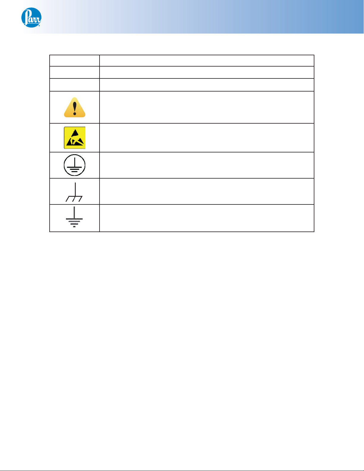
Explanation of Symbols
I On position
O Off Position
~ Alternating Current (AC)
Proximate Interface
This CAUTION symbol may be present on the Product Instrumentation and literature. If present on the product, the user must consult
the appropriate part of the accompanying product literature for more
information.
ATTENTION, Electrostatic Discharge (ESD) hazards. Observe precau-
tions for handling electrostatic sensitive devices.
Protective Earth (PE) terminal. Provided for connection of the Protec-
tive Earth (green or green/yellow) supply system conductor.
Chassis Ground. Identifi es a connection to the chassis or frame of the
equipment shall be bonded to Protective Earth at the source of supply
in accordance with national and local electrical code requirements.
Earth Ground. Functional earth connection. Note: This connection shall
be bonded to Protective earth at the source of supply in accordance
with national and local electrical code requirements.
General Specifi cations
Electrical Ratings
115VAC, 2.0 Amps. 50/60 Hz
230VAC, 2.0 Amps, 50/60 Hz
Before connecting the 6750 Proximate Interface
to an electrical outlet, the user must be certain that
the electrical outlet has an earth ground connection
and that the line, load and other characteristics of
the installation do not exceed the following limits:
Voltage: Fluctuations in the line voltage should not
exceed 10% of the rated nominal voltage shown on
the data plate.
Frequency: 6750 Proximate Interface units can be
operated from either a 50 or 60 Hertz power supply
without affecting their operation or calibration.
Current: The total current drawn should not exceed
the rating shown on the data plate on the unit by
more than 10 percent.
Environmental Conditions
Operating:
15 ºC to 40 ºC; maximum relative humidity of
80% non-condensing.
Installation Category II (overvoltage) in accordance with IEC 664.
Pollution degree 2 in accordance with IEC 664.
Altitude Limit: 2,000 meters.
Storage:
-25 ºC and 65 ºC; 10% to 85% relative humidity.
Cleaning & Maintenance
Periodic cleaning may be performed on the
exterior surfaces of the instrument with a lightly
dampened cloth containing mild soap solution. All
power should be disconnected when cleaning the
instrument. There are no user serviceable parts
inside the product other than what is specifi cally
called out and discussed in this manual. Advanced
troubleshooting instructions beyond the scope of
this manual can be obtained by calling Parr Instrument Company in order to determine which part(s)
may be replaced or serviced.
Fuses
Lines protective fuses rated: Fast-Act 15 Amp,
250VAC (Parr number 139E23).
The replacement of protective fuses for the 6750
Proximate Interface should be performed by qualifi ed personnel.
www.parrinst.com
5
Page 7
Proximate Interface
Installation
This apparatus is to be used indoors. It requires
at least 2 square feet of workspace on a sturdy
bench or table in a well-ventilated area with convenient access to an electric outlet. The supply voltage
must be within ± 10% of marked nominal voltage on
the apparatus. The supply voltage receptacle must
have an earth ground connection.
Balance Port Connections
The balance driver software in the 6750 Proximate Interface has been confi gured to operate with
a wide variety of balances. The following three balance protocols are supported:
1. Mettler
2. Sartorius
3. A & D
A fourth “generic” protocol is provided which
may, in many cases work with other balances that
are not directly supported. The user should fi rst
study the input specifi cation of the generic format
for compatibility with the intended balance if it is
not one of the fi rst three protocols listed above.
Other balances may be supported if their output
formats are compatible with the above four balances or a generic format which is supported by the
6750 Proximate Interface. Parr can supply the cables
for the balance port to balance connection. The
cables are listed in the
chapter of this manual.
Balances with an RS232C output will need to use
the 2203E RS232 to USB converter.
Data and Communications
be transferred to an Ethernet network connected
computer using the FTP File Transfer Protocol. By
default, the network interface is turned off. The
Interface can be confi gured to use DHCP (Dynamic
Host Confi guration Proticol) or have a static or fi xed
IP address. It is recommended, that any network
confi guration parameters only be set or altered after
consulting with your network administrator. Further
details related to the Ethernet port can be found in
the chapter that specifi cally addresses the data and
communication specifi cations.
Start Up
Once the appropriate cable connections have
been made, the unit is ready to be turned on by
moving the main power switch on the back of the
instrument to the on (I) position. The unit will display the Parr logo in the upper left hand corner of
the LCD, followed by a running description of the
instrument boot sequence. This boot sequence ends
when the instrument Main Menu is displayed.
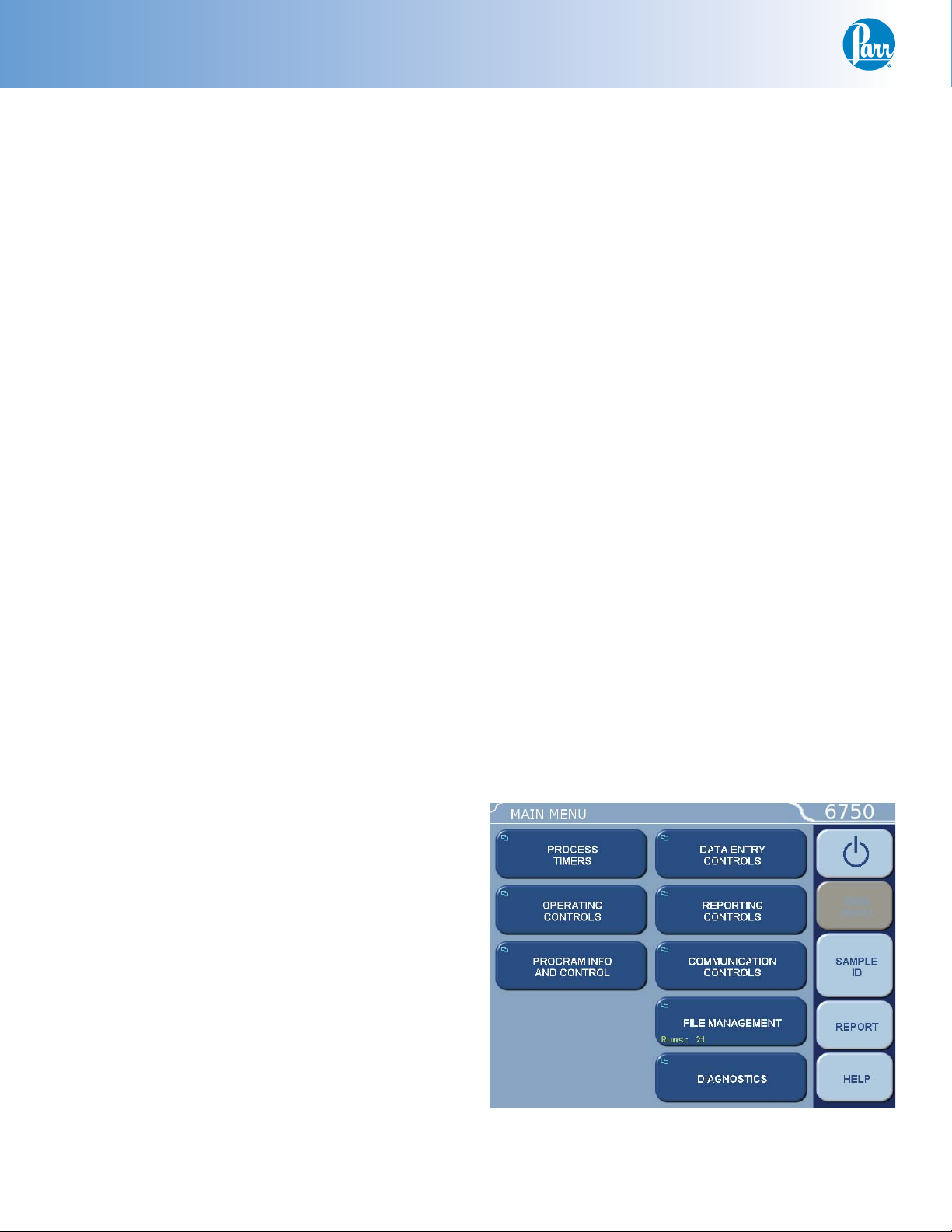
Instrument Description
Types of Controls
All confi gurations and operations are handled
by a menu-driven system operated from the bright
touch screen display. The settings and controls are
organized into ten main sections as displayed on the
MAIN MENU.
Note: Keys with a “double box” in the upper left
hand corner lead to sub-menus.
Printer Port Connections
The USB Ports on the 6750 Proximate Interface
may be used for connection to either a 40 or 80-column printer. Before making either of these connections, the data transmission rate of the 6750 Proximate Interface and the printer must be matched.
Parr offers the 1758 Printer for use with the 6750
Proximate Interface. An A2170E cable (supplied with
the printer) is used to connect the 6750 Proximate
Interface to the 1758 Printer. The Ethernet network
port can be used for long distance communications.
Ethernet Network Port
The Interface uses the TCP/IP protocol to communicate with other devices, such as PC, on a
standard Ethernet network. Interface test data can
6
Parr Instrument Company
Page 8

Proximate Interface
Menu Keys
The controls that change the data fi eld information in the menus will be one of the following:
Toggles. These data fi elds contain ON/OFF or
t
YES/NO choices. Simply touching the key on the
screen toggles the choice to the other option.
The current setting is displayed in the lower
right corner of the key.
Option Selection. These data fi elds contain a list
t
of options. Touching the key on the screen steps
the user through the available choices. The current setting is displayed in the lower right corner
of the key.
Value Entry Fields. These data fi elds are used to
t
enter data into the Interface. Touching the key on
the screen brings up a sub-menu with a keypad
or similar screen for entering the required value.
Some keys lead to multiple choices. Always
clear the current value before entering a new
value. Once entered, the screen will return to
the previous menu and the new value will be
displayed in the lower right corner of the key.
Data Displays. Most of these keys display val-
t
ues that have been calculated by the Interface
and are informational only. The user, entering
a desired value through a sub-menu, can override certain values. The value is displayed in the
lower right corner of the key.
Note: Some keys will respond with an opportunity
for the user to confi rm the specifi ed action to minimize accidental disruptions to the program and/or
stored data.
Control Keys
There are fi ve control keys that always appear
in the right column of the primary displays. These
keys are unavailable when they are gray instead of
white.
Escape. This key is used to go up one level in
1.
the menu structure.
Main Menu. This key is used to return to the
2.
main menu touch screen from anywhere in the
menu structure.
Sample ID. This key is used to start the data
3.
entry sequence for a given analysis.
Report. This key is used to access the test
4.
results stored in the Interface and to initiate a
report on the display or printer.
Help. This key is used to access help screens
5.
related to the menu currently displayed on the
touch screen.
System Shutdown. This key appears in the
ESCAPE key location when the Main Menu is
displayed. Pressing this button will prompt the
user to confi rm a system shutdown.
Program Installation and Control
Software Installation
The program in the Interface can be extensively
modifi ed to tailor the unit to a wide variety of standard test methods, laboratory techniques, and communication modes.
Note: Changes to the program are made by use of
the menu structure described later in this manual.
Any of these items can be individually entered at
any time to revise the operating program.
Factory Default Settings
Units are preprogrammed with DEFAULT SETTINGS. These default settings remain in effect until
changed by the user. Should the user ever wish to
return to the factory default settings, go to the Program Information and Control Menu, touch Reload
Factory Default Settings and YES.
Flash ROM based memory is provided to retain
any and all operator initiated program changes;
even if power is interrupted or the unit is turned off.
User Default Settings
The user default parameters of the Interface can
be changed to guarantee that the instrument will
always be in the desired confi guration before beginning a series of tests.
Users who wish to permanently revise their default settings may do so using the following procedure:
1. Establish the operating parameters to be stored
as the user default settings.
2. Go to the Program Information and Control
Menu, User/Factory Settings, User Setup ID,
and enter the desired User Setup ID (up to eight
characters).
3. Go to the Program Information and Control
Menu, Save User Default Settings, and YES.
4. To re-load the user default settings, go to the
Program Information and Control Menu, Re-load
User Default Settings, and YES.
Note: It is a good idea to enable “protect settings”
on the Interface to prevent them from being inadvertently changed.
www.parrinst.com
7
Page 9

Proximate Interface
Factory Default Settings
Process Timers
Moisture 01:00:00
Ash 04:00:00
VM 00:07:00
Operating Controls
Device Type Proximate Inter-
face
LCD Backlight Timeout 1200
LCD Backlight Intensity 90%
Language English
Program Information & Control
User Setup ID 00000001
Settings Protect Off
Data Entry Controls
Auto Sample ID Controls On
Verify Data On
BTU/Spike Tare Zero
Moisture and Ash Separate
ADL Prompt Order Tare-Gross-Final
FSI Units Fahrenheit
Auto Sample ID Controls
Automatic Sample ID On
Next Auto Sample ID Number 1
Auto Sample ID Increment 1
Data Source Controls
ADL/Total Moisture Source Touchscreen
Moisture Source Touchscreen
Ash Source Touchscreen
Volatile Matter Source Touchscreen
Spike Weight Source Touchscreen
Sulfur Source Touchscreen
BTU Source Touchscreen
BTU Weights Source Touchscreen
Reporting Controls
Report Width 40
Report Format Text
Individual Printed Reports Off
Edit Final Reports Off
Report Inclusions
BTU On
BTU Weights On
Sulfur On
Moisture On
Ash On
Volatile Matter On
ADL/Total Moisture On
FSI On
Ash Fusion On
Spike Weight On
Balance Port Communications
Balance Type Generic
Balance Port Device /dev/ttyUSB0
Balance Port Settings
Number of Data Bits 8
Parity None
Number of Stop Bits 1
Handshaking None
Baud Rate 9600
Characters from Balance 8
Data Precision 4
Transfer T imeout (seconds) 10
Network Communications
DHCP (Automatic Setup) Off
Network Driver Off
8
Parr Instrument Company
Page 10
Proximate Interface
Menu Operating Pages
The 6750 Proximate Interface contains the following keys that lead to sub-menus.
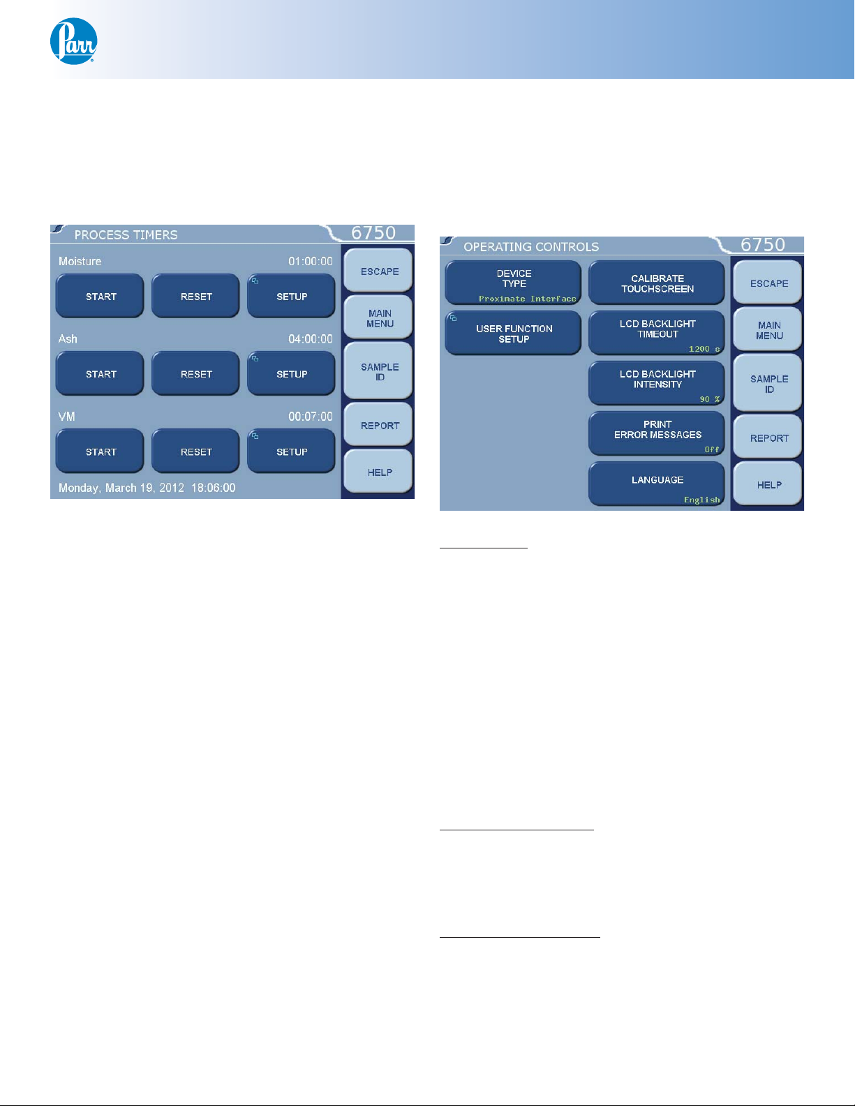
Process Timers
popup is displayed and the prior alarm is queued
underneath it.
The lower portion of the Timers page displays
the current date and time.
Operating Controls
Many of the tests involving proximate analysis
require holding the sample at a set temperature for
a pre-set time. As a result, a series of three independent countdown timers are provided. By default
these timers are labeled Moisture, Ash, and VM after
the most popular items to time. Each timer has three
buttons associated with it. The fi rst button starts and
stops the timer (toggle). The timer value is displayed
to the right of the label in a HH:MM:SS format.
The next button is a reset button that will reload
the timer preset value when the timer is not running. When the timer is running the reset button is
not active.
The third button associated with each timer is a
setup button that leads to a submenu. The submenu
allows the user to change the label and duration
for a timer. Each timer has a series of tones that are
sounded when the timer reaches zero. This alarm is
repeated indefi nitely until it is acknowledged.
When the timer reaches zero, the backlighting is
turned on, if required, and a popup box is displayed
in order to allow acknowledgment of the alarm.
The popup box displays the timer tag. Pressing the
continue button inside the large popup box provides
alarm acknowledgment. If an alarm occurs before an
active one is acknowledged, the most recent alarm
Device Type:
This key allows the user to customize the operation
of the device. Various screens and related prompts
will change depending on what type of device is selected. This setting also determines how the device
is confi gured in a networked environment.
The device options available are:
t Proximate Interface
t ADL Interface
t Total Moisture Interface
t Balance Interface
t Moisture Interface
t Ash Interface
t Volatile Interface
User Function Setup:
This key leads to sub-menus that support the confi guration of fi ve factory/user defi nable function keys.
The function keys are accessible from the Diagnostics page.
Calibrate Touchscreen:
This key prompts the user to touch the screen
at predefi ned points in order to facilitate touch
screen calibration. It’s important that a touch screen
stylus, rather than a fi nger, be used in order to realize an accurate calibration.
www.parrinst.com
9
Page 11
Proximate Interface
Operating Controls (Continued)
LCD Backlight Timeout:
The unit is equipped with an automatic circuit to
shut-off the backlight when it is not being used. The
back light will shut-off if there is no keyboard activity for the number of seconds entered. Touching the
screen will automatically turn the back lighting ON.
A setting of 0 will keep the backlight ON at all times.
LCD Backlight Intensity:
This button provides a slider control that allows
the user to adjust the display backlight intensity for
optimum viewing.
Print Error Messages:
When turned ON, all error messages are printed on
the printer as well as displayed on the screen.
Language:
This button steps the calorimeter through the installed operating languages.
t Time Zone. Displays the selected time zone
in relation to Greenwich Mean Time. Pressing this key will step through the time
zones and automatically adjust the time
setting.
Volume Level Adjust:
Opens a window with a slide adjustment to set the
volume of the key clicks and alarms of the calorimeter. Default is 85%.
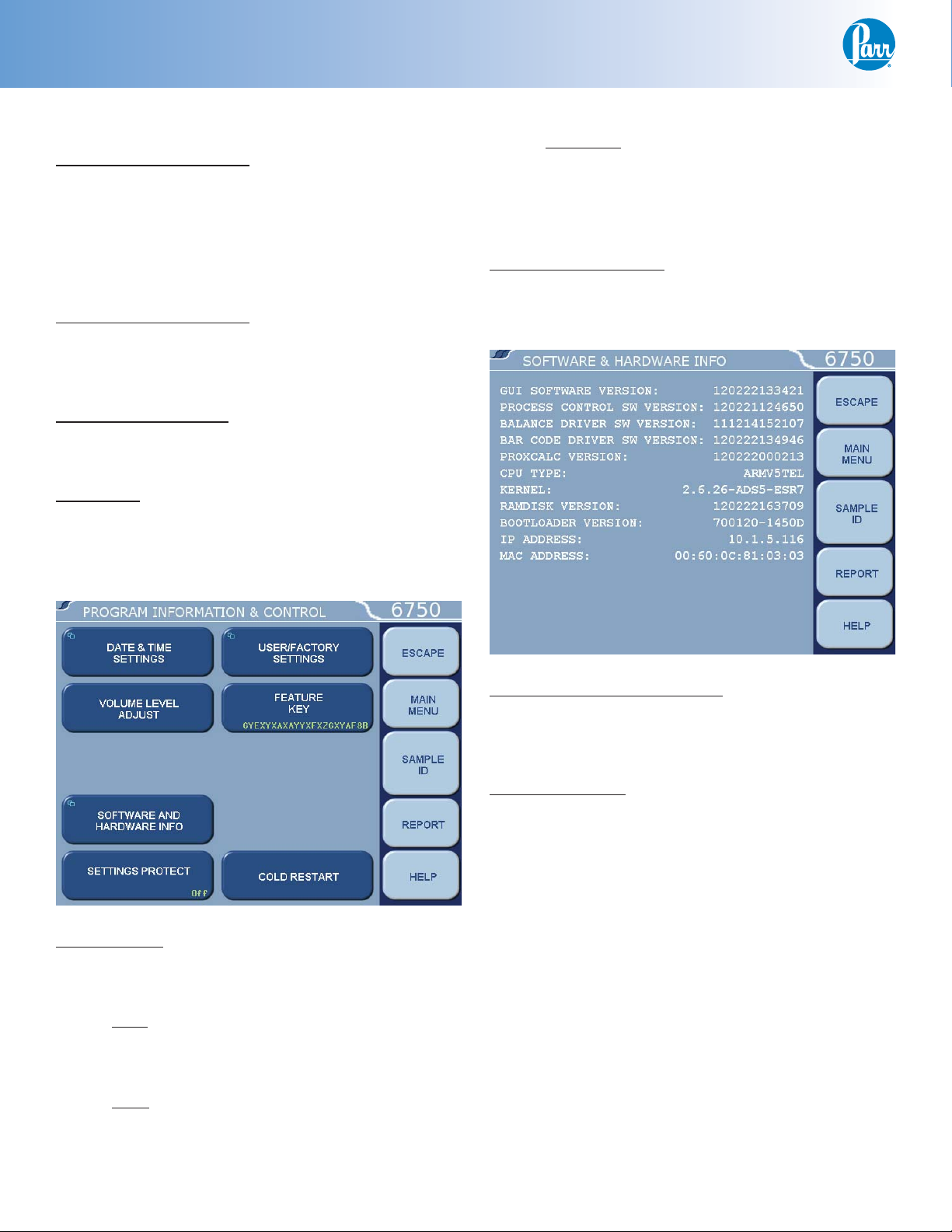
Program Information and Controls
Date & Time:
Accesses a sub-menu to set the current date and
time.
t Date. Displays current date and accesses
sub-menu on which date is set in (YY/MM/
DD) format.
Software and Hardware Info:
This screen displays important information such as
the main software version, I/O board information,
CPU information, and IP address assigned.
Settings Protect:
Provides protection for the program options and
settings on the menus. If this is turned ON, the user
will be warned that enumeration keys are locked
when a key is pressed. Enumeration Keys either
toggle a value (ON/OFF) or select from a predefi ned
list. This feature is used primarily to protect the
instrument settings from accidental changes if one
were to inadvertently touch or bump up against the
touchscreen.
t Time. Displays current time and accesses
sub-menu on which time is set in (HH:MM)
format.
10
Parr Instrument Company
Page 12

User/Factory Settings:
This key leads to a sub-menu that allows the user to
save or recall user defi ned instrument settings. Additionally, factory pre installed settings supporting
different bombs or special operating modes can also
be recalled.
Proximate Interface
Cold Restart:
This is essentially the same as cycling power on the
unit. All valid test data will be retained during this
cold restart procedure.
Data Entry Controls
t User Setup ID. Used to enter a unique identi-
fi er for recalling or saving user settings.
t Reload Factory Default Settings. Used to erase
all of the settings and restore the factory
default settings.
t Reload User Default Settings. Used to restore
the user setup ID settings should the program in the instrument be corrupted for
any reason.
t Save User Default Settings. Used to record the
setup to the memory once the user has
confi gured the instrument to their operating requirements.
t Compare Settings With Factory Defaults.
button will bring up a screen that will show
the differences in the current settings of the
calorimeter with the factory defaults.
This
Feature Key:
This key displays a screen which allows the user to
input a code to access special calorimeter features
such as the bar code capabilities, remote operation
by PC or Samba server feature.
Auto Sample ID Controls:
This key accesses the sub-menu for controlling the
automatic assignment of sample identifi cation numbers.
Verify Data:
When this setting is set to ON, the user must press
the <ENTER> key to store incoming data. The value
may be edited prior to storage. The user may turn
this option ON or OFF.
Btu/Spike Tare:
When this setting is set to Zero, the Btu tare weight
is always equal to zero. The Btu net weight is then
entered as the Btu gross weight. The user may set
this key to Zero or Tare.
Moisture and Ash:
When this setting is set to Combined, it specifi es
that the weights entered for moisture tare, gross
shall be used for ash tare and gross. The user may
set this key to Combined or Separate.
ADL Prompt Order:
This key establishes the ADL or TM weight prompting order: Tare-Gross-Final or Gross-Final-Tare.
FSI Units:
The user may set either degrees Celsius or Fahrenheit.
www.parrinst.com
11
Page 13

Proximate Interface
Data Entry Controls (Continued)
Data Sources:
This key accesses a sub-menu where the user can
select input devices for each of the following types
of data:
Note: Ash fusion and FSI only come from the keyboard.
t ADL/Total Moisture – Touchscreen / Balance Port
/ Network
t Moisture Source – Touchscreen / Balance Port /
Network
t Ash Source – Touchscreen / Balance Port / Net-
work
t Volatile Matter Source – Touchscreen / Balance
Port / Network
t Spike Weight Source - Touchscreen / Balance Port
/ Network
t Sulfur Source – Touchscreen / Balance Port /
Network
t Btu Source – Touchscreen / Balance Port / Net-
work
t Btu Weights Source – Touchscreen / Balance Port
Network Device IP Addresses
This key accesses a sub menu where the user can
input the IP addresses of equipment attached to the
network.
Reporting Controls
Report Width
This key allows the user to select either 40 or 80 column report width. Select 40 when the 1758 Printer
is used.
Report Format
This setting allows the user to select the type of
report format for the printer or device attached to
the local printer port, either Data or Text. When Data
is selected, only numerical items are reported with a
comma delimiter.
Individual Printed Reports
When set to ON, will generate header information
for each report printed. In the OFF position, only one
header will be printed for a series of tests.
Edit Final Reports
When set to ON, this enables the user to revise
sample weights and related values contained in fi nal
reports.
Report Inclusions
This key leads to a submenu that allows the user to
select which analyses (and associated bases) are reported. Proper selection of the tests that correspond
to the types of analyses actually done will determine
when a report becomes fi nal. This selection will also
determine which kinds of test choice keys are displayed during a data entry session.
This key accesses a sub-menu where the user
can establish the report format for the local printer
port.
t Btu
t Btu Weights
t Sulfur
t Moisture
t Ash
t Volatile Matter
t ADL / Total Moisture
t FSI
t Ash Fusion (oxidizing and reducing)
t Spike Weight
12
Parr Instrument Company
Page 14

Proximate Interface
Communication Controls Menu
Accesses sub-menus which set the communications protocols for the printer and balances.
Printer Type:
Toggles between Parr 1758 and Generic.
Balance Port:
Accesses sub-menu, Balance Port Communications.
t Customize Balance Setting. Sets the com-
munication parameters for the balance
port. Standard options for data bits, parity, stop bits, handshaking, baud rate and
balance type are provided to match any
devices that might be connected to these
ports.
» Number of Data Bits. Standard options
for data bits. Toggles between 7 and 8.
» Parity. Standard options for parity.
Choose from None, Even or Odd.
» Number of Stop Bits. Standard options
for stop bits. Toggles between 1 and 2.
» Handshaking. Standard options for hand-
shaking. Choose from None, Xon/Xoff,
and RTS/CTS.
» Baud Rate. Standard options for baud
rate. Choose from 19.2K , 9600, 4800,
2400, 1800, 1200, 600, 300, 150, 134.5,
110, and 75.
» Data Characters from Balance. This
setting is only used when the generic
balance format is selected. This value
determines the number of numeric data
characters (0-9 . + -) to accept. Any additional characters after this value and
before the string terminating <CR> are
discarded.
t Balance Type. Toggles through the available
balance templates.
t Balance Port Device.
screen which allows the user to specify the
balance port device. The default
(dev/ttyUSB0) is the designation for the fi rst
USB to serial converter cable assigned by the
calorimeter upon power up.
This key displays a
» Data Precision. This key allows the user to
establish the number of digits to the right
of the decimal point that are passed from
the balance handler.
» Transfer T imeout (seconds). This value
determines how long the interface will
wait before giving up on a weight transfer. The value is entered in seconds.
www.parrinst.com
13
Page 15

Proximate Interface
Communication Controls Menu (Continued)
» Balance Handler Strings. This key leads to
a submenu that allows balance template
to be customized for unique balances or
needs.
t Log Balance to Display. Directs the incom-
ing data stream from the balance to a display
buffer. This function can be used to deter-
mine the data format from an unknown bal-
ance type. The display buffer is 40 characters
in length. The balance must be forced to is-
sue at least 40 characters before the contents
of the buffer are displayed.
t Balance Port LoopBack Test. Initiates a
loopback test on the port. A special loopback
plug is required in order to perform this test.
Further information on establishing
communications for the Printer, Balance, Network
Interface, Bar Code and other Network Data Devices
can be found in the
and Communication Specifi cations section of this
manual.
Installation section and Data
Users who don’t have a network infrastructure
can create a simple network by connecting a router
with DHCP server capability to the calorimeter using
an ordinary CAT 5 network cable. The unit should be
connected to the LAN side of the router. The PC in
turn is also connected to the LAN side of the router
using a similar CAT 5 cable. A D-link 614+ router is
recommended for this purpose.
For this router, operated without a WAN connection, the primary DNS address of the router (WAN
setup) must be set to the IP address of the router
found on the LAN setup page. Other routers behave
differently in the absence of a WAN connection. Providing an active upstream connection to the WAN
port of most routers generally minimizes the use of
any obscure setup confi gurations.
The Proximate Interface also supports the use of
a static IP address. A static IP address can be assigned from the Network Interface page under Communication Controls.
An FTP enabled web browser can be used to
access stored test data. The URL is of the following
form:
Network Interface
The test data can be transferred to an Ethernet
network connected computer using the FTP File
Transfer Protocol. First you must know the IP address of the network-connected Proximate Interface.
The network DHCP (Dynamic Host Confi guration
Protocol) server provides this address shortly after
the unit is turned on. The address can be seen on
the “Software and Hardware Info” page within the
“Program Information & Control” menu.
ftp://root.rootroot@10.1.5.32/../fl ash/data/
In this case, 10.1.5.32 is the IP address of the
Proximate Interface.
14
Parr Instrument Company
Page 16

Proximate Interface
The following screen shot illustrates the contents of the Proximate Interface data directory as presented
be a web browser.
The user can drag and drop or copy and paste test data fi les (with the csv suffi x) from the web browser
window to any convenient folder or directory on the PC.
The four folders or directories correspond to the device confi guration. For example, if the device is confi gured as a proximate interface device, all entered data is placed in the prox folder or directory. The three
other folders correspond to ADL, total moisture and balance interface devices.
The following screen shot illustrates the typical contents of the prox directory.
www.parrinst.com
15
Page 17

Proximate Interface
You can drag and drop or copy and paste test data fi les (with csv suffi x) from the web browser window
to any convenient folder or directory on the PC.
The Proximate Interface offers a web server service. Test reports can be viewed with a web browser using a URL of the following form:
http://10.1.5.32
16
Parr Instrument Company
Page 18

Proximate Interface
Where 10.1.5.32 is the IP address of the Proximate Interface. The following screen shot illustrates the
Proximate Interface home page.
From this page the Process Timers can be remotely monitored.
Clicking on the Sample Data tab displays a list of reports currently in the instrument memory.
www.parrinst.com
17
Page 19

Proximate Interface
From the Confi guration Page the Error Reporting and Sample ID & Bomb ID options can be set. Changes
made to this screen will change the settings in the 6750.
18
Parr Instrument Company
Page 20

Proximate Interface
On the Run Data screen test data can be reviewed and fi ltered by status and type.
www.parrinst.com
19
Page 21

Proximate Interface
The System Info page displays the Software and Hardware Information page of the 6750.
20
Parr Instrument Company
Page 22

Proximate Interface
File Management Menu
Run Data File Manager:
This key activates the File Manager. The File Manager is used to delete or rename test report fi les. It
is also used to convert fi le types.
Format the SD Card:
This key allows the user to format an installed SD
card in a manner that is compatible with the calorimeter.
Run Data File Manager
The white upper portion of the Run Data File
Manager screen presents all tests in memory in a
scrollable window. Test attributes include fi lename
(sample ID), test type, status, and date. Touching
anywhere in the column related to a given test attribute will sort the fi le list by that attribute. Successive touches will toggle between an ascending and
descending sort.
Note: Formatting will erase all fi les on the card!
Copy Run Data to SD Card:
This key copies all test data to an SD card inserted
into the rear of the calorimeter controller. This feature is used as a means of either archiving data or
transferring it to a PC.
Note: Subsequent use of the same SD card will
overwrite the data currently on the card.
Copy User Settings to SD Card:
This key copies all previously saved user setups to
SD.
Copy User Settings From SD Card:
This key copies all user setups previously saved to
SD back to the calorimeter controller memory. This
feature can be used to confi gure multiple calorimeters in an identical manner.
Select:
This key is used to begin the fi le selection process.
The up/down (single arrow) and page up/page down
(double arrow) keys are used to scroll up and down
the fi le list. Pressing the select key when a fi le is
highlighted blue will highlight the fi le with a cyan
color. This indicates that it is selected. Multiple fi les
throughout the list can be selected in this fashion.
Extend Sel:
This key selects all fi les between the last fi le selected and the fi le that is highlighted in blue.
Desel All:
This key deselects all fi les previously selected.
Rename:
This key allows the user to rename the blue highlighted fi lename.
Delete:
This key deletes all selected fi les.
Edit:
This key allows one or more selected tests to be
edited from determinations to standardizations and
vice versa.
www.parrinst.com
21
Page 23

Proximate Interface
Diagnostics
View System Log :
This key is used to display the contents of /fl ash/log/
messages. This fi le is used primarily to log application program debug messages.
View System Information:
This screen illustrates current operating system
information / statistics such as:
t Processes and their associated PIDs
t Memory
t Mass storage
t Network
View Instrument Log :
This screen displays the contents of /tmp/instlog.
Operating Instructions
Data Entry & Operation
There is a basic method for identifying and entering sample weight data into the 6750 Proximate
Interface. Settings are available through the Data
Entry Controls page to speed this process in the following situations.
t When consecutive Sample IDs are used.
t When gross and tare weights are entered con-
secutively.
t When only net weights are entered for Btu deter-
minations.
t When results are entered as percentages.
t When the same sample is used for both mois-
ture and ash determinations.
22
For dealing with these unique situations, the operator should be familiar with the data entry procedure, which is identical for air dry loss, total moisture, residual moisture, ash, volatile matter, sulfur,
Btu weights and/or values.
Parr Instrument Company
Page 24

Proximate Interface
Basic Data Entry Procedures
Pressing the SAMP ID key starts the data entry
sequence. This will prompt the operator to enter
the sample identifi cation string through the touch
screen (up to sixteen characters permitted). Next,
the operator presses the test identifi cation key,
MOIST, ASH, VM to identify the test followed by the
weight identifi cation key, TARE, GROSS, FINAL that
identifi es the weight. More than one weight identifi cation key can be selected. Most procedures call for
pressing both the tare and gross key initially.
The Interface will prompt for the tare weight of
the crucible followed by the gross weight. All this
time the Sample ID number and the selected test
and weight type(s) will be displayed. Once these
are verifi ed, the operator presses the ENTER key to
enter this identifi cation information. The display will
prompt the operator for weight information with a
prompt.
BTU Weight Entry
The 6750 Proximate Interface can be used as a
balance interface device to enter and store sample
weights for calorimetric tests. The weight entry process uses the BTU test identifi cation key followed
by pressing the gross key. Alternately the Date Entry
Controls page can be set to prompt for the tare
weight for those balances that do not have an automatic tare function.
BTU & Sulfur Value Entry
Btu and Sulfur values may be retrieved from
calorimeters or manually entered through the touch
screen. Entries on the Data Sources page controls
this choice. To enter these values, press the SAMP
ID and enter the sample identifi cation number.
Press the BTU or Sulfur key followed by ENTER. In
the retrieval mode, the appropriate value will be
transferred from a calorimeter to the display of the
Interface.
Weights are automatically transferred from the
balance when confi gured by pressing the <TRANSFER> key or they can be entered manually through
the keypad. The value can be verifi ed by the operator and entered into the 6750 Proximate Interface by
pressing the ENTER key, unless the automatic store
feature has been enabled. The basic weight entry
process is complete and can be repeated for the
next sample or weight. Moisture, ash, and volatile
matter can also be entered as percentages from the
keyboard by pressing the SAMP ID key, entering the
sample number, followed directly by ENTER which
causes a prompt for the percent value to be entered.
Once verifi ed, this value can be entered into the
Interface by pressing ENTER. If Btu values in the calorimeter or controller are preliminary values, then
any Btu or Sulfur values found by the Interface will
not be accepted. In the manual mode the operator
simply keys in the value in response to the prompt.
Btu and Sulfur values should be entered into the
Interface as “as determined values”.
www.parrinst.com
23
Page 25

Proximate Interface
Air Dried Loss or Total Moisture Entry
Air Dried Loss (ADL) or Total Moisture (TM)
weights are identifi ed with the corresponding key. A
report fi le can contain ADL or TM data but not both.
Entering one kind of data excludes the other from
being entered unless the other is cleared by editing
the report. The total moisture value is numerically
equal to moisture as received.
Settings on the Data Entry and Controls page
determine the ADL and TM prompting order for
data entry. Users having a second 6750 Proximate
Interface confi gured as an ADL or TM Interface may
obtain these data from the remote interface via the
Ethernet port. Settings on the Data Entry and Controls page control the source of the ADL or TM data.
The procedure for obtaining the ADL or Total
Moisture Weights from a remote interface is the
same as a manual entry procedure. To expedite
ADL or TM weights from a remote device, the recommended procedure is to press all three weight
identifi cation keys (TARE, GROSS and FINAL) before
the enter key when obtaining weights from a remote
6750 ADL or TM Interface. No information will be
sent, even if only one datum is requested, unless
all three weights have been entered into the remote
interface.
Ash Fusion Entry
Ash Fusion values are identifi ed with the corresponding keys. The user can choose either Ash
Fusion Oxidizing or Ash Fusion Reducing. Once this
choice is made the following four critical point temperature keys are displayed.
t IT, Initial deformation temperature
t ST, Softening temperature
t HT, Hemispherical temperature
t FT, Fluid temperature
Any number of these keys can be pressed. The
Interface will then prompt for the corresponding
value(s). Typical values for this test range from 1470
F (800 C) to 2900 F (1600 C). Values are reported to
the nearest unit. The reporting units, degrees C or F,
for the critical point temperatures is set on the Data
Entry and Controls page.
FSI Entry
Pressing the FSI key will simply initiate a prompt
for a numerical value for the free swelling index of
the sample, displayed to the nearest tenth of a unit.
The typical range of values is zero to 12.
Automatic Sample ID Increment Option
The basic data entry procedure can be modifi ed
to streamline the entry of data, and to adapt it to the
individual user’s operation procedures. One method
of modifying these procedures is through the use
of the Auto Sample ID Controls. When this option is
turned on, the Interface will automatically increment
the Sample ID by the value indicated on the Auto
Sample ID Controls page and prompt for a new set
of values each time a data entry sequence is completed.
24
Parr Instrument Company
Page 26

Proximate Interface
Batch Input Mode
The block input mode consists of allowing the
6750 Proximate Interface to automatically prompt
for and/or acquire data for ID’s that already exist in
the memory of the Interface. This type of transfer
is especially useful, but not limited to, transfers of
BTU, Sulfur, ADL and Total Moisture data from remote devices.
Batch Mode:
A patch list is a set of sample ID’s. This list is created
by recording or played back by playing one of 8 possible Batch Lists:
[1-5], [2-6], [3-7], [4-8]
The batch lists are selected by pressing the desired batch number. To toggle to the upper or lower
4 batch ID’s press the batch ID button a second time.
Delete:
This button deletes the sample ID at the current position in the batch list.
Rewind, Back, Forward, Fast Forward:
These buttons are used to skip over or repeat sample ID’s when playing back a batch list. This is useful if your batch becomes out of sequence or if you
wish to edit a batch list.
Play, Stop:
When batch list Play is selected and the batch list is
empty, a warning dialog is displayed and the batch
mode stays in the prior state. When a Sample ID
would normally be prompted for the next ID in the
batch list is displayed. When the end of the batch
list is encountered the batch mode is returned to the
Idle state.
Record, Stop:
When Record is selected all subsequent sample ID
entries are appended tot he end of the currently
selected list. Recording continues until the user
presses the stop button.
Mode:
This button toggles between Bock Mode and Single
Mode of sample ID entry. In Block Mode the ending
sample ID entry. In Block Mode the ending sample
ID is enabled and may be edited.
Accept:
Accepts the currently displayed sample ID and begins data prompts.
Each batch list contains 0 or more sample ID’s.
Upload:
The Upload button is used to upload copies of the
currently selected batch list to all devices specifi ed
in the network data device lists. The Upload button
is disabled when the batch list is on record mode.
Erase:
To completely erase a batch list press Erase with
batch list selected. You will be prompted to confi rm
this operation.
Play, Record, Idle:
Batch lists are in one of 3 states. All non-selected
batch lists are in the Idle state. A selected batch list
can be Idle, Playing, or Recording.
www.parrinst.com
25
Page 27

Proximate Interface
Reporting Instructions
The 6750 Proximate Interface can transmit formatted data over the USB port to a 40 or 80 column
printer to provide a printed report. Alternatively, test
reports can be transferred over the Ethernet network
to a specifi ed network printer. In addition to the
cabling and communication requirements contained
in the
Proximate Interface must be correctly programmed
to format and direct the report to the desired printing device. These options are set up Reporting
Controls page. In addition to the options available
for printing the report, the 6750 Proximate Interface
offers a wide selection of data and information that
can be included in the reports. The user can choose
to eliminate any tests not appropriate to his or her
work. All calculations and reporting by the 6750
Proximate Interface are performed in accordance
with the ASTM Methods listed in
in this manual.
Report Generation
Reports can be broadly classifi ed into one of two
categories: Preliminary and Final.
Installation chapter of this manual, the 6750
References section
the cursor. Press the SELECT key to actually enter
the selection. Once selected the highlight will turn
from dark blue to light blue. Scrolling through the
list and selecting individual fi les can select a series
of tests.
The double up and down keys will jump the cursor to the top or bottom of the current display.
If a range of tests is to be selected, select the
fi rst test in the series, scroll the selection bar to the
last test in the series and press EXTEND SELECT to
select the series. The DESELECT ALL key is used to
cancel the current selection of fi les.
To bring the selected report or series of report
to the display, press the DISPLAY key. To send the
reports to the printer press the PRINT key.
Editing Reports
t 1SFMJNJOBSZ3FQPSUTBSFHFOFSBUFEXIFOBMM
operator specifi ed data have not been completely
entered. When a report is fl agged as preliminary,
the operator or supervisor can quickly identify the
sample(s) requiring attention.
t 'JOBMSFQPSUTBSFHFOFSBUFEPODFBMMPGUIFPQFSB
tor specifi ed items have been entered into the fi le.
Test results are stored as fi les using the sample
ID number as the fi le name. Pressing the REPORT
command key accesses a listing of the stored results. The REPORT command key brings up a submenu on which the operator specifi es.
Select From List:
This key displays the stored results specifi ed with
the following key.
Run Data State
This key enables the operator to display only preliminary reports, only fi nal reports, or all stored reports.
The displayed fi les can be sorted by sample
ID number, by status or by date of test by simply
touching the appropriate column.
The EDIT key on this fi le selection screen brings
up a dialog box that enables the operator to edit any
of the data in the report or add additional data in
order to convert preliminary reports to fi nal reports.
Pressing the <CLEAR> key immediately followed by
the <ENTER> key will reset the entered bit associated with the given datum. Final reports can only be
edited if Edit Final Reports on the Reporting Controls
Menu is turned on.
Individual fi les can be chosen by highlighting
them using the up and down arrow keys to move
26
Parr Instrument Company
Page 28

Proximate Interface
Memory Management
The 6750 Calorimeter will hold data for 1000
tests in its memory. These tests may be pre weights,
preliminary or fi nal reports for either standardization or determination runs. Once the memory of the
controller is fi lled, the controller will not start a new
analysis until the user clears some of the memory.
The FILE MANAGEMENT key on the main menu
leads to the fi le management sub-menu. The RUN
DATA FILE MANAGER key leads to a listing of the
fi les. Single fi les can be deleted by highlighting the
fi le and pressing the DELETE key. The controller will
then ask the user to confi rm that this fi le is to be
deleted. A series of fi les can be deleted by selecting
the fi rst fi le in the series and then the last fi le in the
series using the EXTEND SEL key and then pressing
the DELETE key.
The controller of the 6750 Calorimeter can accept SD memory cards, Parr part number 2201E.
These cards can be used to:
Copy test fi le data for transfer to a computer
Copy user settings for back up
Reload user settings to the controller
Restore or update the controller’s operating
system.
Copy the log fi le
SD memory cards are inserted into either slot on
the back of the control section of the Calorimeter.
Keys are provided on the FILE MANAGEMENT submenu to initiate each of the above actions except
restoring or updating the controller’s operating
system and copying the log fi le.
www.parrinst.com
27
Page 29

Proximate Interface
Data & Communication Specifi cations
6750 Run Data Template
The following list illustrates the order in which the data is presented in a proximate analysis data fi le. A
comma separates each datum.
1 A Sample ID (char[16])
2 B Timestamp (MM/DD/YY HH:MM:SS
3 C State (1=preliminary, 2=fi nal)
4 D Status 1 (0 – 65535)
5 E Status 2 (0 – 65535)
6 F Moisture Tare Wt.
7 G Moisture Gross Wt.
8 H Moisture Final Wt.
9 I Ash Tare Wt.
10 J Ash Gross Wt.
11 K Ash Final Wt.
12 L Volatile Tare Wt.
13 M Volatile Gross Wt.
14 N Volatile Final Wt.
15 O ADL Tare Wt.
16 P ADL Gross Wt.
17 Q ADL Final Wt.
18 R TMoist Tare Wt.
19 S TMoist Gross Wt.
20 T TMoist Final Wt.
21 U Btu Tare Wt.
22 V Btu Gross Wt.
23 W Btu Net Wt.
24 X ADL
25 Y Moisture as determined
26 Z Ash as determined
27 AA Volatile as determined
28 AB Fixed Carbon as determined
29 AC Sulfur as determined
30 AD Btu as determined
31 AE Moisture as received
32 AF Ash as received
33 AG Volatile as received
34 AH Fixed Carbon as received
35 AI Sulfur as received
36 AJ Btu as received
37 AK Ash Dry
38 AL Volatile Dry
39 AM Fixed Carbon Dry
40 AN Sulfur Dry
41 AO Btu Dry
42 AP Sulfur Dry Ash Free
43 AQ Btu Dry Ash Free
44 AR Volatile Dry Ash Free
45 AS Fixed Carbon Dry Ash Free
46 AT FSI
47 AU Ash Fusion temperature units 0=F, 1=C
48 AV Ash Fusion-reducing-IT
49 AW Ash Fusion-reducing-ST
50 AX Ash Fusion-reducing-HT
51 AY Ash Fusion-reducing-FT
52 AZ Ash Fusion-oxidizing-IT
53 BA Ash Fusion- oxidizing -ST
54 BB Ash Fusion- oxidizing -HT
55 BC Ash Fusion- oxidizing –FT
56 BD Btu Spike Tare Wt.
57 BE Btu Spike Net Wt.
58 BF Btu Spike Gross Wt.
28
Parr Instrument Company
Page 30

Proximate Interface
Filename Convention
Test data fi les are named with the following convention.
Test type Filename
Preliminary <ID>.plim.csv
Final <ID>.fi nl.csv
Balance Input Driver Specifi cations
Overview
The 6750 Proximate Interface supports input
from the three balance types indicated below. Additionally, a generic input driver is provided for
communications with balances that do not conform
to the directly supported protocols. A feature supported by all balance input drivers is the ability to
change the expected number of characters in the
data fi eld. The number of data characters indicated
for each of the drivers, below, are default values.
This feature virtually eliminates the need for balance
input drivers to be re-written in the event the balance manufacturer elects to alter the output string
of a balance when new models are introduced.
The format of an unknown balance can be determined by logging the balance output to display. In
order for the logging to produce meaningful results,
the cable connecting the balance to the balance
input port of the Interface must be correctly wired
or confi gured. In addition, the specifi cs of the data
frame, such as the baud rate, # of data bits, parity, #
of stop bits and handshaking (if used) must be the
same for both the balance and the Interface.
Mettler 011/012 Interface
Field Length
ID 2
space 1
data 9
space 1
g1
CR 1
LF 1
The ID fi eld must contain “S_” to indicate a
stable mass. The data fi eld contains the current
mass, right justifi ed, with a decimal point. The balance should be confi gured to send continuously.
Mettler MT-SICS
Field Length
ID 2
stability 1
space 1
data 10
space 1
g1
CR 1
LF 1
The ID fi eld must contain “S_” to indicate a stable mass. The data fi eld contains the current mass,
right justifi ed, with a decimal point. The balance
should be confi gured to transmit data upon receipt
of the following command string:
S [CR] [LF]
Note: The automatic data output option should not
be used.
The interface will send this command string
once after the PROCEED key has been pressed
during a mass entry sequence. The PROCEED key
should only be pressed when the mass reading is
stable. However, unstable readings will be rejected
and a warning will be issued. Acknowledging the
warning by pressing the CLEAR ENTRY key will restart the mass entry process all over again.
Sartorius Balance Interface
Field Length
polarity 1
space 1
data 8
space 1
stability 2
CR 1
LF 1
The polarity fi eld must contain either a “+” or a
space. Leading zeros in the data fi eld are blanked,
except for the one to the left of the decimal point
The balance should be confi gured to transmit data
upon receipt of the following command string:
[ESC] P [CR] [LF]
Note: The automatic data output option should not
be used.
www.parrinst.com
29
Page 31

Proximate Interface
Sartorius Balance Interface (Continued)
The interface will send this command string
once after the PROCEED key has been pressed
during a mass entry sequence. The PROCEED key
should only be pressed when the mass reading is
stable. However, unstable readings will be rejected
and a warning will be issued. Acknowledging the
warning by pressing the CLEAR ENTRY key will restart the mass entry process all over again.
A&D Standard Format (type 0)
Field Length
header 2
comma 1
data 9
units 3
CR 1
LF 1
The header fi eld must contain “ST” to indicate
stable mass. The data fi eld contains the current
mass, with leading zeros, and a decimal point.
Technical Service
Should you need assistance in the operation or
service of your instrument, please contact the Technical Service Department.
Telephone: (309) 762-7716
Toll Free: 1-800-872-7720
Fax: (309) 762-9453
Email: parr@parrinst.com
Any correspondence must include the following
basic information:
1. The model and serial # of the instrument.
2. Date purchased.
3. Software version(s) shown on the “Software and
Hardware Information” page.
Generic Interface
Field Length
data 2
CR 1
The data fi eld should consist of 8 numeric characters (0 through 9,+,- and space) terminated with a
carriage return (CR).
Leading zeros may be blanked as spaces and are
counted. Non-numeric characters are ignored and
will reset the input buffer if the data fi eld has not
been fi lled. Any characters received after fi lling the
data fi eld and before the carriage return are ignored.
Parr Balance Interface Cables
Part # Description
A1880E 9 pin DS to 25 pin DP S-T
A1881E 9 pin DS to 25 pin DP Null
A1882E 9 pin DS to 25 pin DS S-T
A1883E 9 pin DS to 25 pin DS Null
A1884E 9 pin DS to 9 pin DP S-T
A1885E 9 pin DS to 9 pin DP Null
A1886E 9 pin DS to 9 pin DS S-T
A1887E 9 pin DS to 9 pin DS Null
2203E USB to Serial Adapter
4. Help system revision. This is displayed by press-
ing the <MAIN MENU> key and then the <HELP>
key.
When calling by phone, it is helpful if the person
is close to the instrument in order to implement
any changes recommended by the Technical Service
Department.
Return for Repair
To return the instrument for repair, please call
the Technical Service Department for shipping
instructions and a RETURN AUTHORIZATION NUMBER. This number must be clearly shown on the
outside of the shipping carton in order to expedite
the repair process.
Ship repair to:
Parr Instrument Company
Attn: Service Department
211- 53rd Street
Moline, Illinois 61265
30
Parr Instrument Company
Page 32

Proximate Interface
References
1. ASTM D2013 Standard Method of preparing Coal Samples for Analysis.
2. ASTM D3172 Standard Practice for Proximate Analysis for Coal and Coke.
3. ASTM D3173 Standard Test Method for Moisture in the Analysis Sample of Coal and Coke.
4. ASTM D3174 Standard Test Method for Ash in the Analysis Sample of Coal and Coke from Coal.
5. ASTM D3175 Standard Test Method for Volatile Matter in the Analysis Sample of Coal and Coke.
6. ASTM D3180 Standard Method for Calculating Coal and Coke Analyses as Determined to Different Bases.
7. ASTM D2961 Standard Test Method for Total Moisture in Coal Reduced to #8 Top Sieve Size.
8. ASTM D3302 Standard Test Method for Total Moisture in Coal.
9. ASTM D720 Standard Test Method for Free-Swelling Index of Coal.
10. ASTM D1857 Standard Test Method for Fusibility of Coal and Coke Ash
11. ASTM D5865 Standard Test Method for Gross Calorifi c Value of Coal and Coke
www.parrinst.com
31
Page 33

Proximate Interface
Figures
Figure 1
6750 Proximate Interface - Internal Parts View
(2) 1157E FUSE HOLDER
139E14 FUSE
TN1140HL
(2) 200F2
FUSE LABELS
353C2
BACK PANEL
911E FILTER
W/(2) TN1140HL
909E
POWER SWITCH
A1821E
SPEAKER ASSEMBLY
W/(2) SN1140HLHJ
A2167E
USB CABLE ASSY
W/(2) SA1140RP06
TYP (2) PLACES
(4) TA1332PP06X
351C2
BASE
1796E POWER SUPPLY
W/(4) SA1140RP06
325C HINGE
W/(4) TN1332HL
MF2154E
CPU BOARD
W/(4) SA1140RP06
WARNING:
For continued protection against possible hazard, replace
fuses with same type and rating of fuse.
32
Parr Instrument Company
Page 34

Figure 2
3
6750 Proximate Interface - Back View
Proximate Interface
1472DD
DISPLAY
ENCASEMENT
(4) TN1140HL
Figure 3
6750 Proximate Cover Panel - Internal View
352C2
COVER
F
1477DD
DISPLAY
(4) TN13
www.parrinst.com
33
Page 35

Proximate Interface
TRANSITION
BOARD TO
W/A2141E)
A2165E
(REF SUPPLIED
Figure 4
6750 Proximate Interface Schematic
REF
A2165E
DISPLAY
CABLE
IN THIS VIEW
CONTACTS ARE
EXPOSED
DETAIL "A"
A2141E
BOARD
LCD TRANSISTION
1472DD
LCD ENCASEMENT
A
J1
J10
J6
J9
J2
J8
2147E
LCD DISPLAY
CABLE
ASSEMBLY
SPEAKER
A1821E
A2164E BACKLIGHT CONTROL CABLE ASSY
J1
A1823E2 TOUCH
SCREEN CABLE ASSY
A2163E LCD CABLE ASSY
J5
J17J19
J100
J4
J8
J1
BACK PANEL
USB PORT 1
A2167E USB PERIPHERAL
OF J4 OF CPU
CABLE ASSY
CONNECTS IN UPPER PORT
J6
R1
BACK PANEL
USB PORT 2
CABLE ASSY
A2167E USB PERIPHERAL
CONNECTS IN LOWER PORT
OF J4 OF CPU
A1822E POWER CABLE ASSY
CN2
POWER
1796E
CN1
J10 J9
A2154E
CPU BOARD
SUPPLY
34
Parr Instrument Company
Page 36

Revision 05/18/12
 Loading...