

Page 1
Operating Instruction Manual 454M
6510
Water Handling System
Page 2
6510 Water Handling System Operating Instruction Manual
Operating Instructions
For the 6510 Water Handling System
Purpose
The 6510 Water Handling System acts as a cooling and circulating water source for
maintaining a constant jacket temperature in the 6200 Isoperibol Calorimeter. It also
provides a convenient and consistent means for filling the bucket in a Parr 6200 or 6100
Compensated Jacket Calorimeter. Either one or two 6200 Calorimeters can be served
from a single 6510 System.
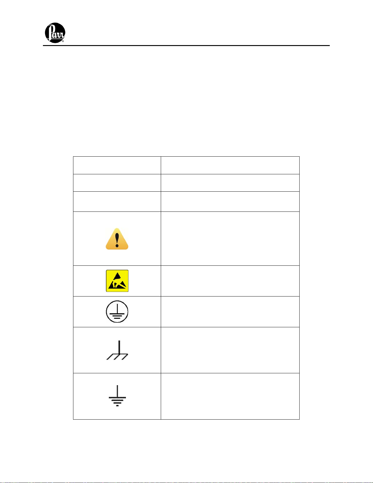
Explanation of Symbols
I
O
~
On position
Off position
Alternating Current (AC)
This CAUTION symbol may be present on
the Product Instrumentation and literature. If
present on the product, the user must
consult the appropriate part of the
accompanying product literature for more
information.
ATTENTION, Electrostatic Discharge (ESD)
hazards. Observe precautions for handling
electrostatic sensitive devices.
Protective Earth (PE) terminal. Provided
for connection of the protective earth (green
or green/yellow) supply system conductor.
Chassis Ground. Identifies a connection to
the chassis or frame of the equipment shall
be bonded to Protective Earth at the source
of supply in accordance with national and
local electrical code requirements.
Earth Ground. Functional earth connection.
NOTE: This connection shall be bonded to
Protective earth at the source of supply in
accordance with national and local electrical
code requirements.
- 2 -
Page 3

6510 Water Handling System Operating Instruction Manual
Safety Information
To avoid electrical shock, always:
1. Use a properly grounded electrical outlet of correct voltage and current handling
capability.
2. Ensure that the equipment is connected to electrical service according to local
national electrical codes. Failure to properly connect may create a fire or shock
hazard.
3. For continued protection against possible hazard, replace fuses with same type
and rating of fuse.
4. Disconnect from the power supply before maintenance or servicing.
To avoid personal injury:
1. Do not use in the presence of flammable or combustible materials; fire or
explosion may result. This device contains components which may ignite such
material.
2. Refer servicing to qualified personnel.
Intended Usage
If the instrument is used in a manner not specified by Parr Instrument Company, the
protection provided by the equipment may be impaired.
General Specifications
Electrical Ratings
115VAC, 2.0 Amps. 50/60 Hz
230VAC, 2.0 Amps, 50/60 Hz
Before connecting the water handling system to an electrical outlet, the user must be
certain that the electrical outlet has an earth ground connection and that the line, load
and other characteristics of the installation do not exceed the following limits:
Voltage: Fluctuations in the line voltage should not exceed 10% of the rated nominal
voltage shown on the data plate.
Frequency: Water handling systems can be operated from either a 50 or 60 Hertz
power supply without affecting their operation or calibration.
Current: The total current drawn should not exceed the rating shown on the data plate
on the water handling system by more than 10 percent.
Environmental Conditions
Operating: 15 ºC to 30 ºC; maximum relative humidity of 80% non-condensing.
Installation Category II (overvoltage) in accordance with IEC 664.
Pollution degree 2 in accordance with IEC 664.
Altitude Limit: 2,000 meters.
Storage: -25 ºC and 65 ºC; 10% to 85% relative humidity.
- 3 -
Page 4

6510 Water Handling System Operating Instruction Manual
Description
The system consists of a 20 liter, temperature controlled, tank with a built in circulating
pump, an attached glass delivery pipet and provision for continuous filtration of all water
in the system. This is a closed circuit system in which water is re-used continuously.
When the 6510 System is used with a 6200 Calorimeter, water from the tank is
delivered to the temperature control manifold at the rear of the calorimeter and returned
in a closed loop, thereby maintaining a constant temperature in the calorimeter.
The water handling system can be used to supply water not only to the calorimeter
jacket but also to the bucket through an attached delivery pipet. The choice of oxygen
bomb size will dictate the pipet choice as follows:
Oxygen Bomb Pipet Volume Pipet Part Number Support Assembly
1108 2000 mL 167HW A335HW
1104 1850 mL 167HW2 A335HW
1109 450 mL 167HW3 A335HW2
A maximum of two pipets may be installed on the water handler. Only one pipet may be
filling the bucket at any one time.
Temperature controlled water flows continuously through the glass delivery pipet and
back to the tank to maintain a constant water temperature in the pipet for filling the
calorimeter bucket with repeatable volumes. Flow through the pipet stops when the
stopcock is opened to fill the calorimeter bucket. The pipet refills automatically when
the stopcock is turned back to a closed position. At the end of each test, the user will
empty the bucket water into the reservoir where it is released slowly into the tank so as
not to cause a sudden change in temperature.
NOTE: Do not leave the stopcock dry as the Teflon will seize in the glass.
Incorporated in the system is a solid-state water chiller that is capable of removing and
dissipating the heat in the returned bucket water produced during calorimetric testing,
thus maintaining the water at a constant temperature for repeatable test temperatures.
Required Accessories and Utilities
Approximately 15 L of water with a total hardness of less than 85 ppm is required for
filling the tank of the system.
- 4 -
Page 5

6510 Water Handling System Operating Instruction Manual
Installation
Install the 6510 System near the calorimeter so that the water connections are kept
short. The water system can be installed in any convenient location however care
should be taken that heat from the compressor on the left side of the Water Handling
System not reach the calorimeter. Additionally, air must be allowed to move freely
around the cooling fan on the back of the 6510 System. The supply voltage must be
within ± 10% of marked nominal voltage on the instrument. The supply voltage
receptacle must have an earth ground connection.
Make the tubing connections as illustrated in Figure-1.
Note: It is critical to keep the tubing between the calorimeter and the water
system as short as possible and eliminate any uphill runs or kinks. This
will impede the free flow of water from the calorimeter.
Pipet Installation
The A335HW pipet support brackets can be installed on either side of the water
handling system. There are four mounting screws (TA1632PP06) located on each side
of the water handler. The pipet is installed by slightly tilting and inserting the round top
portion of the pipet into the hole in the pipet support. The lower support bracket holds
the pipet from underneath by inserting the pipet into the slotted end of the bracket.
Insert the 148C, 3-way PTFE stopcock plug into the pipet and secure it using only
enough tension on the spring loaded retaining nut to prevent leakage. Insert the short
3
/8” OD Nylon tube into a three-inch length of black latex tubing furnished with the
system. Attach the tubing to the discharge tube that extends downward from the
stopcock. This provides a flexible tip to prevent breakage if the bucket were to strike
the discharge tube during the filling operation. Extending the discharge tube into the
bucket also minimizes splashing of the water while the bucket is filling.
3
The pipet outlet on the back panel is a
/8” tube connection. A 219HW barb connector is
provided to install the JR0056TB125A tubing. Install a 6” piece of JR0056TB125A
tubing on the barb connector. Install the 149C in-line filter; make sure the arrow on the
filter is pointing towards the pipet. Install JR0056TB125A tubing from the 149C filter to
the bottom port of the pipet. The pipet return on the back panel is a ½” tube connection.
A 309HW barb connector is provided to install the JR0056TB125A tubing. Install tubing
from the 309HW barb connector to the top port on the pipet.
Note: It is critical to keep the tubing from the pipet to the water handler as
short as possible. Any extra tubing can create a downward loop in the tube
and potentially back up the water, restricting the flow.
- 5 -
Page 6

6510 Water Handling System Operating Instruction Manual
Tubing Connections
Water connections are not required for the 6100 Calorimeter.
The two external water connections are made using the ¼” Nylon tubing, P/N
HJ0025TB035, furnished with the system. For each connection, cut the end of the tube
squarely with a knife or tubing cutter.
The cooling water connections at the rear of the calorimeter use compression fittings.
Insert the tubing into the fitting as far as it will go and then tighten the nut ¾ of a turn
from finger tight. Subsequent connections are made by threading on the nut by hand
and then tightening slightly with a wrench. These compression fittings can be overtightened causing a leak in the system.
Provisions for Lifting and Carrying
Before moving the instrument, disconnect all connections from the rear of the
apparatus. Lift the instrument by grabbing underneath each corner.
Operation
Using water with less than 85 ppm total hardness, fill the water tank. Take care not to
fill the tank with water higher than the tube that enters through the back of the tank
(approximately 4 inches from the top of the reservoir).
Check the voltage requirements of the water handler by examining the data label found
on the back of the unit. Plug the power cord into a suitable electrical outlet. Turn on the
water handling system by flipping the switch to the “ON” position. Monitor the amount of
water in the water tank. Add water as required to maintain the water level in the
reservoir. Check for water leaks in the external lines and fix as required.
Check the voltage requirements of the calorimeter by examining the data label found on
the back of the unit. Fill the tank on the back of the unit as described in the calorimeter
operating manual. (It may be necessary to tip the calorimeter forward slightly to ensure
no air bubbles are trapped in the line.) Plug in the power cord to a suitable electric
outlet. Turn on the calorimeter by flipping the switch to the “ON” position.
Note: Do not turn on the calorimeter heater and pump until the calorimeter
jacket is full otherwise damage can occur to the unit.
- 6 -
Page 7

6510 Water Handling System Operating Instruction Manual
Preventative Maintenance
All power should be disconnected when cleaning or servicing the instrument. The
following preventative maintenance for the 6510 Water Handling System is
recommended:
Monitor the amount of water in the water tank and add water as required to
maintain the water level in the reservoir.
Clean the grill on the heat sink at the rear of the Water Handler monthly. Using
compressed air to perform this is a quick and easy way to remove the dust. Wipe
exterior surfaces with lightly dampened cloth containing mild soap solution.
Change the water in the tank monthly.
Change the in-line filter, 149C, every 3 months
Replace the 3/8” OD tubing, HX0038TB062, annually
Add an anti-microbial solution, such as VWR Clear Bath Algicide (13272-031),
per the manufacturer’s instructions.
The pipet can be cleaned with a 1:10 dilution of Acetic Acid or straight vinegar.
The reservoir can be easily emptied by repeatedly draining the pipet until the circulating
pump is sucking air. When this occurs, turn the power switch at the rear of the system
to the OFF position. Do not let the pump run dry for more than a few minutes.
There are no user serviceable parts inside the product other than what is specifically
called out and discussed in this manual. Advanced troubleshooting instructions beyond
the scope of this manual can be obtained by calling Parr Instrument Company in order
to determine which part(s) may be replaced or serviced.
Fuses
Lines protective fuses rated: Slo-Blo 4.0 Amp, 250VAC (Parr number 139E20)
Fast-Act 15 Amp, 250VAC (Parr number 139E23)
The replacement of protective fuses for the 6510 Water Handling System should be
performed by qualified personnel.
- 7 -
Page 8

6510 Water Handling System Operating Instruction Manual
Parts List
Part No. Description
108C Spout, Polyethylene 3”
110C Tubing, Black Latex 3”
139E20 Fuse 3AG Slo-Blo 250VAC 4.0 Amp
139E23 Fuse Fast/ Act 15 Amp 250VAC
149C In-Line Filter
172HW2 Cap, Receiver Cover; Lt Grey
1795E Power Supply, 24V
1850E Relay, SS 10 Amp; 3-60VDC Input
187HW O-ring NBR 1-5/16ID x 3/32CS
210HW Union, Bulkhead;
212HW Union, Bulkhead;
219HW Connector, Barb
1
/4T
3
/8”T
3
/8”T-3/8”
230HW Tube Elbow Union 3/8T-T Stem
251HWHJ Hose Barb Union Conn 1/2T-1/4T
286HW Insulator, Temp Manifold 6510
302HW Tube Elbow Union 1/4T-3/8T Stem
303HW Adapter, ½ NPT O-ring seal
307HW Cross Union,
3
/8T Truseal
309HW Connector, Barb ½ Stem-3/8”T-3/8”
304HW Union, Bulkhead; ½”T
309HW Connector, Barb ½ Stem-3/8ID
A1851E2 Controller,
1
/32 DIN (6510)
A284HW Chiller Assembly 6510
A298HW Tube Assembly (6510)
A2261HW Pump Assembly, 24VDC
HJ0025TB035 Tubing, Nylon, ¼ OD X .035W
JR0056TB 125A 5/16 ID x .125W Latex Black
JT0056TB062A Tube, 9/16 OD X 7/16 ID Tygon
JU0038TB062A Tubing Polyurethane ¼ ID X 1/16 W
WARNING: For continued protection against possible
hazard, replace fuses with same type and rating of fuse.
- 8 -
Page 9

6510 Water Handling System Operating Instruction Manual
Figure 1
- 9 -
Page 10

6510 Water Handling System Operating Instruction Manual
Figure 2
- 10 -
Page 11

6510 Water Handling System Operating Instruction Manual
Figure 3A
- 11 -
Page 12

6510 Water Handling System Operating Instruction Manual
Figure 3B
- 12 -
Page 13

6510 Water Handling System Operating Instruction Manual
Figure 4A
- 13 -
Page 14

6510 Water Handling System Operating Instruction Manual
Figure 4B
WARNING: For continued protection against possible hazard,
- 14 -
replace fuses with same type and rating of fuse.
Page 15

6510 Water Handling System Operating Instruction Manual
Figure 5
- 15 -
Page 16

PARR INSTRUMENT COMPANY
211 Fifty-Third Street
Moline, Illinois 61265 USA
309/762-7716 800/872-7720
Fax 309/762-9453
http://www.parrinst.com E-Mail: parr@parrinst.com
Revision 09/14/12
 Loading...