

Page 1
6100
Compensated Jacket Calorimeter
Operating Instruction Manual
For models produced after October 2010
584M
Page 2

Page 3

Table of Contents6100
Preface 3
Scope 3
Related Instructions 3
Explanation of Symbols 4
Safety Information 4
Intended Usage 4
General Specifications 4
Environmental Conditions 5
Provisions for Lifting and Carrying 5
Cleaning & Maintenance 5
Getting Started 5
Chapter 1 6
Concept of Operation 6
Overview 6
Compensated Jacket Operation 6
Dynamic Operation 7
Full Microprocessor Based Process Control 7
Full Microprocessor Based Data Acquisition and Handling 7
Flexible Programming 7
Chapter 4 14
Program Installation & Control 14
Software Installation 14
Default Settings 14
Revising Default Settings 14
Chapter 5 18
Operating Instructions 18
Operating the 1108P Oxygen Combustion Vessel 18
Operating the Filling Connection 18
Operating the Calorimeter 18
Samples and Sample Holders 20
Combustion Aids 20
Oxygen Charging Pressure 20
Combustion Capsules 20
Foodstuffs and Cellulosic Materials 21
Coarse Samples 21
Corrosive Samples 21
Explosives and High Energy Fuels 22
Volatile Sample Holders 22
Poor Combustion 23
Chapter 2 8
Installation 8
Environmental Conditions 8
Required Consumables, Utilities and Power Requirements 8
Oxygen Filling Connection 8
Printer and Balance Connections 8
Standardizing the Calorimeter 8
Swagelok Tube Fittings 9
Retightening Swagelok Tube Fittings 9
Chapter 3 12
Instrument Description 12
Types of Controls 12
Menu Keys 13
Control Keys 13
Chapter 6 24
Corrections & Final Reports 24
Entering Corrections and Obtaining the Final Report 24
Manual Entry 24
Fixed Corrections 24
Chapter 7 26
Reporting Instructions 26
Report Option Section 26
Report Generation 26
Net Heat of Combustion 27
Chapter 8 28
File Management 28
Clearing Memory 28
Removable SD Memory Cards 28
www.parrinst.com
1
Page 4

Table of Contents
Chapter 9 30
Maintenance & Troubleshooting 30
Oxygen Bomb 30
Fuses 30
6100 Calorimeter Error List 31
Appendix A 32
Menu Operating Instructions 32
Calorimeter Operation Menu 32
Temperature vs. Time Plot Screen 32
Temperature Plot Setup Menu 33
Operating Controls Menu 34
Spiking Correction 34
Program Information and Control Menu 35
User/Factory Settings 35
Bomb 1 37
Bomb Control Chart 37
Thermochemical Calculations Menu 38
Calculation Factors 38
Net Heat/Dry Heat Factors 39
Data Entry Controls Menu 40
Net Heat Data Entry Controls 40
Auto Sample ID Controls 40
Moisture Data Entry Controls 41
Auto Preweigh Controls 41
Reporting Controls Menu 42
Communication Controls Menu 42
Balance Port Communications 43
File Management 44
Diagnostics Menu 44
ASTM Treatment for Acid and Sulfur 49
ISO Calculations 50
Spiking Samples 50
Conversion to Other Moisture Bases 51
Conversion to Net Heat of Combustion 51
Appendix C 52
Standardization 52
Standardizing the Calorimeter 52
Standard Materials 52
Automatic Statistical Calculations 52
Appendix D 56
Communications Interfaces 56
USB Port for Connection 56
Balance and Port Input Driver Specifications 56
Mettler 011/012 Balance Interface 56
Sartorius Balance Interface 56
Generic Interface 57
Network Interface 58
Samba Server Feature (Optional) 59
Bar Code Port 67
Network Data Devices 67
Appendix E 68
Technical Service 68
Contact Technical Service 68
Return for Repair 68
Appendix B 46
Calculations 46
Calculating the Heat of Combustion 46
General Calculations 46
Thermochemical Corrections 46
ASTM and ISO Methods Differ 47
Fuse Correction 47
Acid and Sulfur Corrections 48
2
Parr Instrument Company
Appendix F 70
Parts Lists & Drawings 70
Principal Assemblies in Calorimeter 70
Parts List for A1279DD2 Controller Assembly 70
Parts List for A1284DD2 Stirrer Hub Assembly 70
Parts List for Oxygen Filling System 71
6100 Stirrer Motor and Drive Parts List 71
Printer and Supplies 71
Spare and Installation Parts List 71
Page 5

6100
Preface
Figures
Swagelok Tube Fittings 10
6100 Compensated Jacket Calorimeter Back Panel 11
2811 Pellet Press 20
3601 Gelatin Capsules 21
43A6 Combustion Capsule with Adhesive Tape Seal 21
43AS Combustion Capsules 21
Combustion Capsule with Adhesive Tape Seal 22
6100 Compensated Jacket Calorimeter Cutaway Front 72
6100 Compensated Jacket Calorimeter Cutaway Rear 73
A1279DD2 Control Schematic 74
A1278DD Oxygen Solenoid Assembly 75
A1284DD2 Stirrer Hub Assembly 76
Stirrer Motor Assembly 77
Customer Service
Questions concerning the installation or operation of this instrument
can be answered by the Parr Customer Service Department:
Tables
Factory Default Settings 16
Settings for ISO & BSI Methods 49
Calorimeter Control Limit Values in J/g When Benzoic
Acid is Used as a Test Sample 53
Calorimeter Control Limit Values in cal/g When Benzoic
Acid is Used as a Test Sample 54
Calorimeter Control Limit Values in BTU/lb When Benzoic
Acid is Used as a Test Sample 55
6100 Data File Naming Convention 57
6100 Calorimeter Run Data Template 57
1-309-762-7716 • 1-800-872-7720 • Fax: 1-309-762-9453
E-mail: parr@parrinst.com • http://www.parrinst.com
Preface
Scope
This manual contains instructions for installing and
operating the Parr 6100 Calorimeter. For ease of use,
the manual is divided into nine chapters.
Concept of Operation
Installation
Instrument Description
Program Installation & Control
Operating Instructions
Corrections & Final Reports
Reporting Instructions
File Management
Maintenance & Troubleshooting
Subsections of these chapters are identified in the
Table of Contents.
To assure successful installation and operation, the
user must study all instructions carefully before
starting to use the calorimeter to obtain an understanding of the capabilities of the equipment and the
safety precautions to be observed in the operation.
Related Instructions
Additional instructions concerning the installation
and operation of various component parts and peripheral items used with the 6100 Calorimeter have
been included and made a part of these instructions.
No. Description
201M Limited Warranty
483M Introduction to Bomb Calorimetry
418M 1108P Oxygen Combustion Vessel
207M Analytical Methods for Oxygen Bombs
Additional instructions for the printer are found in
the respective package and should be made a part
of this book.
Note: The unit of heat used in this manual is
the International Table calorie, which is equal
to 4.1868 absolute joules.
www.parrinst.com
3
Page 6
Preface
Explanation of Symbols
I On Position
O Off Position
~ Alternating Current
This CAUTION symbol may be present on the Product Instrumentation and literature. If present on the product, the user must consult
the appropriate part of the accompanying product literature for more
information.
ATTENTION, Electrostatic Discharge (ESD) hazards. Observe precautions for handling electrostatic sensitive devices.
Protective Earth (PE) terminal. Provided for connection of the protec-
tive earth (green or green/yellow) supply system conductor.
Chassis Ground. Identifies a connection to the chassis or frame of the
equipment shall be bonded to Protective Earth at the source of supply
in accordance with national and local electrical code requirements.
Earth Ground. Functional earth connection. This connection shall be
bonded to Protective earth at the source of supply in accordance with
national and local electrical code requirements.
Safety Information
To avoid electrical shock, always:
1. Use a properly grounded electrical outlet of correct voltage and current handling capability.
2. Ensure that the equipment is connected to electrical service according to local national electrical codes. Failure to properly connect may create
a fire or shock hazard.
3. For continued protection against possible hazard, replace fuses with same type and rating of
fuse.
4. Disconnect from the power supply before maintenance or servicing.
To avoid personal injury:
1. Do not use in the presence of flammable or com-
bustible materials; re or explosion may result.
This device contains components which may
ignite such material.
Intended Usage
If the instrument is used in a manner not specified
by Parr Instrument Company, the protection provided by the equipment may be impaired.
General Specifications
Electrical Ratings
115VAC, 2.0 Amps. 50/60 Hz
230VAC, 2.0 Amps, 50/60 Hz
Before connecting the calorimeter to an electrical
outlet, the user must be certain that the electrical
outlet has an earth ground connection and that the
line, load and other characteristics of the installation
do not exceed the following limits:
Voltage: Fluctuations in the line voltage should not
exceed 10% of the rated nominal voltage shown on
the data plate.
Frequency: Calorimeters can be operated from
either a 50 or 60 Hertz power supply without affecting their operation or calibration.
2. Refer servicing to qualified personnel.
4
Parr Instrument Company
Current: The total current drawn should not exceed
the rating shown on the data plate on the calorimeter by more than 10 percent.
Page 7

6100
Preface
Environmental Conditions
Operating: 15 ºC to 30 ºC; maximum relative humidity of 80% non-condensing. Installation Category II
(over voltage) in accordance with IEC 664.
Pollution degree 2 in accordance with IEC 664.
Altitude Limit: 2,000 meters.
Storage: -25 ºC and 65 ºC; 10% to 85% relative
humidity.
Provisions for Lifting and Carrying
Before moving the instrument, disconnect all connections from the rear of the apparatus. Lift the
instrument by grabbing underneath each corner.
Cleaning & Maintenance
Periodic cleaning may be performed on the exterior
surfaces of the instrument with a lightly dampened
cloth containing mild soap solution. All power
should be disconnected when cleaning the instrument. There are no user serviceable parts inside the
product other than what is specifically called out
and discussed in this manual. Advanced troubleshooting instructions beyond the scope of this
manual can be obtained by calling Parr Instrument
Company in order to determine which part(s) may
be replaced or serviced.
Getting Started
These steps are offered to help the user become
familiar with, install, operate and develop the full
capabilities of the Parr 6100 Calorimeter.
1. Review the Concept of Operations, Chapter 1, to
get an understanding of the overall capabilities
of the calorimeter and microprocessor control.
2. Unpack and install the calorimeter in accordance
with the Installation Instructions, Chapter 2. This
simple, step-wise procedure will acquaint the
user with the various parts of the calorimeter
and make it easier to understand the operating
instructions which follow.
3. Turn the power switch ON (located on the back).
Turn to the Instrument Description, Chapter 3, to
review the touch screen controls.
4. Review the Program Installation and Control,
Chapter 4, to match the factory settings to the intended mode of operation. Any required changes
can be made to the program parameters located
in the Main Menu.
5. Review the Reporting Instructions, Chapter 7, to
become familiar with the manner in which calorimetry corrections are entered. Also discussed
are generating final reports, editing and clearing
memory.
6. Turn to the Menu Operating Instructions, Ap-
pendix A, to review the menu functions used
to modify the program contained in the 6100
Calorimeter. A review of the menus will provide
a good idea of the capabilities and exibility
designed into this instrument.
7. Review the Calculations, Appendix B. This pro-
vides information about calculations performed
by the 6100 Calorimeter.
8. Review Standardization, Appendix C. This will
serve two important functions. First, it provides
instructions on generating the energy equivalent
factor required to calculate the heat of combustion of unknown samples. Secondly, it will give
the user the opportunity to run tests on a material with a known heat of combustion to become
familiar with the instrument and confirm that the
instrument and operating procedures are producing results with acceptable precision. Most
6100 Calorimeters will have an energy equiva-
lent of approximately 2400 calories per ºC. The
runs for standardization and determinations are
identical, except for the setting of the instrument
to the standardization or determination mode.
9. Review the Communication Interfacing, Appendix D, for the correct installation of any peripherals connected to the 6100 Calorimeter.
10. After successful standardization, the 6100 Calorimeter should be ready for testing samples.
Note About Nomenclature:
Historically, burning a sample enclosed in a
high pressure oxygen environment is known
as Oxygen Bomb Calorimetry and the vessel
containing the sample is known as an Oxygen
Bomb. The terms bomb and vessel are used
interchangeably.
www.parrinst.com
5
Page 8

1
Concept of Operation
chaPter 1
Concept of Operation
Overview
The 6100 Calorimeter has been designed to provide
the user with:
The Model 6100 can also be equipped with a vari-
ety of special purpose oxygen bombs for unusual
samples and/or applications. The 1104 High Strength
Oxygen Combustion Vessel is designed for testing
explosives and other potentially hazardous materials.
The 1109A Semimicro Oxygen Combustion Vessel can
be fitted along with its unique bucket to test samples
ranging from 25 to 200 mg.
• A traditional design calorimeter with removable
oxygen bomb and bucket.
• A moderately priced calorimeter which uses real
time temperature measurements to determine
heat leaks without using a controlled calorimeter
jacket.
• A full featured calorimeter that does not require
circulating water.
• A compact calorimeter requiring minimum
laboratory bench space.
• A modern intuitive graphical user interface for
ease of operation and training.
• A calorimeter with up to date digital hardware,
software and communications capabilities.
• A calorimeter that is cost effective and which can
incorporate a user’s current bombs, buckets, and
accessories.
Removable Bomb
The Model 6100 Calorimeter utilizes the Parr 1108P
Oxygen Combustion Vessel. More than 20,000 of the
1108 style oxygen combustion vessels have been
placed in service on a world wide basis. This bomb
features an automatic inlet check valve and an adjustable needle valve for controlled release of residual
gasses following combustion. They are intended for
samples ranging from 0.6 to 1.2 grams with a maximum energy release of 8000 calories per charge.
The 1108P Oxygen Combustion Vessel is made of
high-strength, high nickel stainless steel designed
to resist the corrosive acids produced in routine fuel
testing. An alternative 1108PCL vessel is available,
constructed of an alloy containing additional cobalt
and molybdenum to resist the corrosive conditions
produced when burning samples containing chlorinated compounds.
Removable Bucket
The A391DD removable bucket has been designed to
hold the bomb, stirrer and thermistor with a minimum volume of water and to provide an effective
circulating system which will bring the calorimeter to
rapid thermal equilibrium both before and after firing.
Compensated Jacket Operation
The 6100 Calorimeter is intended for the user who
wants a calorimeter with the convenient automatic
features provided in a modern isoperibol calorimeter,
but whose precision requirements can be met with a
static system. To meet these criteria, the temperature
controlled water jacket and its accessories have
been removed from the 6200 Isoperibol Calorimeter
and replaced with an insulating jacket around the
bucket chamber. This eliminates all water and water
connections, resulting in a significant saving in cost.
To obtain the best precision with an uncontrolled
jacket, the 6100 Calorimeter has temperature monitoring capability built into the jacket. This allows the
calorimeter to measure the actual jacket temperature
and apply the appropriate heat leak corrections in
real time. While, not equal to a controlled jacket, the
6100 method offers a significant improvement over
the traditional static jacket and makes it possible to
obtain reasonable precision without the long preand post-periods normally required for static jacket
calorimetry. It also makes it possible to use the Parr
Dynamic Method for rapid testing. As with all static
jacket calorimeters, best results are obtained when
the instrument is operated in a location where it is
not subject to air drafts and fluctuating temperatures. The preferred operating environment is in a
temperature controlled room (+/- 1 C). It is a well
accepted principle of reliable analysis that any instrument calibration be checked regularly. The optimum
frequency for checking the 6100 Calorimeter depends
largely on the temperature stability of the operating
environment. As general rule, the instrument calibration should be evaluated at least every tenth test. The
calorimeter controller software conveniently offers
both a graphical control chart approach in addition to
6
Parr Instrument Company
Page 9

6100
Concept of Operation
1
an automatic rolling average calculation to support
calibration maintenance and verification. Following
the aforementioned guidelines and using reference
samples, such as benzoic acid, the process sigma
(precision classification) of the 6100 Calorimeter can
be taken as 0.1%.
Dynamic Operation
In its Dynamic Operating Mode, the calorimeter uses
a sophisticated curve matching technique to compare
the temperature rise with a known thermal curve to
extrapolate the nal temperature rise without actually waiting for it to develop. Repeated testing, and
over 20 years of routine use in fuel laboratories, has
demonstrated that this technique can significantly
cut the time required for a test by one-half without
significantly affecting the precision of the calorimeter.
Full Microprocessor Based Process Control
The microprocessor controller in this calorimeter has
been pre programmed to automatically prompt the
user for all required data and control input and to:
• Generate all temperature readings in the calorimeter.
• Monitor jacket as well as bucket temperature.
• Collect and store all required test data.
• Apply all required corrections for combustion
characteristics.
• Compute and report the heat of combustion for
the sample.
Flexible Programming
The fifth generation software built into this calorimeter and accessed through the screen menus permit
the user to customize the operation of the calorimeter
to meet a wide variety of operating conditions including:
• A large selection of printing options.
• Choice of accessories and Peripheral equipment.
• Multiple options in regard to handling
thermochemical corrections.
• Choice of ASTM or ISO Correction procedures.
• A variety of memory management and reporting
procedures.
• Complete freedom for reagent concentrations and
calculations.
• Confirm equilibrium conditions.
• Fire the bomb.
• Confirm that ignition has occurred.
• Determine and apply all necessary heat leak cor-
rections.
• Perform all curve matching and extrapolations
required for dynamic operation.
• Terminate the test when it is complete.
• Monitor the conditions within the calorimeter and
report to the user whenever a sensor or operating
condition is out of normal ranges.
Full Microprocessor Based Data Acquisition and Handling
In addition to its process control functions, the microprocessor in the calorimeter has been pre programmed to:
• Unlimited choice of reporting units.
• Automatic bomb usage monitoring and reporting.
• A choice of Equilibrium or Dynamic test methods.
• Automatic statistical treatment of calibration runs.
• Enhanced testing and trouble shooting procedure.
The 6100 Calorimeter is equipped with a universal
serial bus (USB) connection for communication with
a printer, balance, or other device. If more than one
device is to be used at the same time a USB hub will
need to be used. It is also equipped with an Ethernet
network connection for connections to laboratory
computers.
www.parrinst.com
7
Page 10

2
Installation
chaPter 2
Installation
Environmental Conditions
The 6100 Calorimeter is completely assembled and
given a thorough test before it is shipped from the
factory. If the user follows these instructions, installation of the calorimeter should be completed with
little or no difficulty. If the factory settings are not
disturbed, only minor adjustments will be needed to
adapt the calorimeter to operating conditions in the
user’s laboratory.
This apparatus is to be used indoors. It requires at
least 4 square feet of workspace on a sturdy bench or
table in a well-ventilated area with convenient access
to an electric outlet, running water and a drain.
Required Consumables, Utilities and Power Requirements
The 6100 Calorimeter System requires availability of
Oxygen, 99.5% purity, 2500 psig maximum.
The power requirements for the subassemblies of the
6100 Calorimeter are:
Calorimeter
115VAC, 2.0 Amps. 50/60 Hz
230VAC, 2.0 Amps, 50/60 Hz
Printer
100 to 240 VAC, 0.35 Amps 50/60 Hz
Plug the power line into any grounded outlet providing proper voltage that matches the specification on
the nameplate of the calorimeter. The calorimeter will
draw approximately 100 watts of power. Grounding is
very important not only as a safety measure, but also
to ensure satisfactory controller performance. If there
is any question about the reliability of the ground
connection through the power cord, run a separate
earth ground wire to the controller chassis.
Turn the power switch to the on position. After a short
time, the Parr logo will appear on the LCD display
followed by a running description of the instrument
boot sequence. When the boot sequence is complete,
the calorimeter Main Menu is displayed.
Oxygen Filling Connection
The 6100 Calorimeter is equipped with an automatic
bomb oxygen lling system. This system consists of
an oxygen pressure regulator with a relief valve that
mounts on an oxygen tank and a controlled solenoid
inside the calorimeter. To install the regulator on the
oxygen supply tank, unscrew the protecting cap from
the oxygen tank and inspect the threads on the tank
outlet to be sure they are clean and in good condition. Place the ball end of the regulator in the outlet
and draw up the union nut tightly, keeping the gages
tilted slightly back from an upright position. Connect
the regulator to the oxygen inlet tting on the back of
the calorimeter case. This hose should be routed so
that it will not kink or come in contact with any hot
surface. Connect the high-pressure nylon hose with
the push on connector to the oxygen bomb outlet
connection on the back of the calorimeter.
All connections should be checked for leaks. Any
leaks detected must be corrected before proceeding.
Instructions for operating the filling connection are in
the Operating Instructions chapter. Adjust the pressure regulator to deliver 450 psi of O2. Assemble the
oxygen bomb without a charge and attach the lling
hose to the bomb inlet valve. Press the O2 Fill key
on the Calorimeter Operation page and observe the
delivery pressure on the 0 – 600 psi gage while the
oxygen is owing into the bomb. Adjust the regulator, if needed, to bring the pressure to 450 psi. If there
is any doubt about the setting, release the gas from
the bomb and run a second check.
Printer and Balance Connections
Connect the printer to the calorimeter at this time.
The Parr 1758 Printer is configured and furnished with
a cord to connect directly to the USB port on the back
of the calorimeter.
The balance port connection, if needed, should be
made at this time. If both a printer and a balance will
be used then a USB hub will need to be installed.
Contact Parr to determine the correct cable to connect
the balance to the calorimeter.
Standardizing the Calorimeter
The calorimeter must be accurately standardized
prior to actually performing calorimetric tests on
sample materials. Review Appendix C - Standardization, in order to become familiar with the general
8
Parr Instrument Company
Page 11
6100
Installation
2
procedure and calculations. The user should configure the calorimeter at this time to accommodate the
desired sample weight entry mode. The calorimeter
can be placed into standardization mode on the
Calorimeter Operation Page, with the operating mode
key. If multiple bombs and buckets are being used
with the calorimeter to maximize sample throughput, the calorimeter can be configured to prompt
for a Bomb ID at the start of each test. The Bomb ID
can also be selected on the Calorimeter Operations
Page, using the Bomb/EE key. Both bomb and bucket
combinations will need to be standardized separately.
The end result of a standardization test is an energy
equivalent value, or the amount of energy required to
raise the temperature of the calorimeter one degree.
Repeated standardization with any given bomb and
bucket combination should yield an energy equivalent value with a range of 14 calories per degree,
centered around the mean value for all tests using
that bomb bucket combination. The calorimeter is
ready for testing samples after an energy equivalent
value has been obtained.
Swagelok Tube Fittings
When Swagelok Tube Fittings are used, the instructions for installation are:
original position with a wrench. An increase in resistance will be encountered at the original position. Then tighten slightly with a wrench. Smaller
tube sizes (up to 3/16” or 4mm) take less tightening to reach the original position than larger tube
sizes. The type of tubing and the wall thickness
also has an effect on the amount of tightening required. Plastic tubing requires a minimal amount
of additional tightening while heavy wall metal
tubing may require somewhat more tightening. In
general, the nut only needs to be tightened about
1/8 turn beyond nger tight where the ferrule
seats in order to obtain a tight seal.
Over tightening the nut should be avoided. Over
tightening the nut causes distortion (flaring) of the lip
of the tube fitting where the ferrule seats. This in turn
causes the threaded portion of the body to deform.
It becomes difficult to tighten the nut by hand during
a subsequent re-tightening when the fitting body
becomes distorted in this manner.
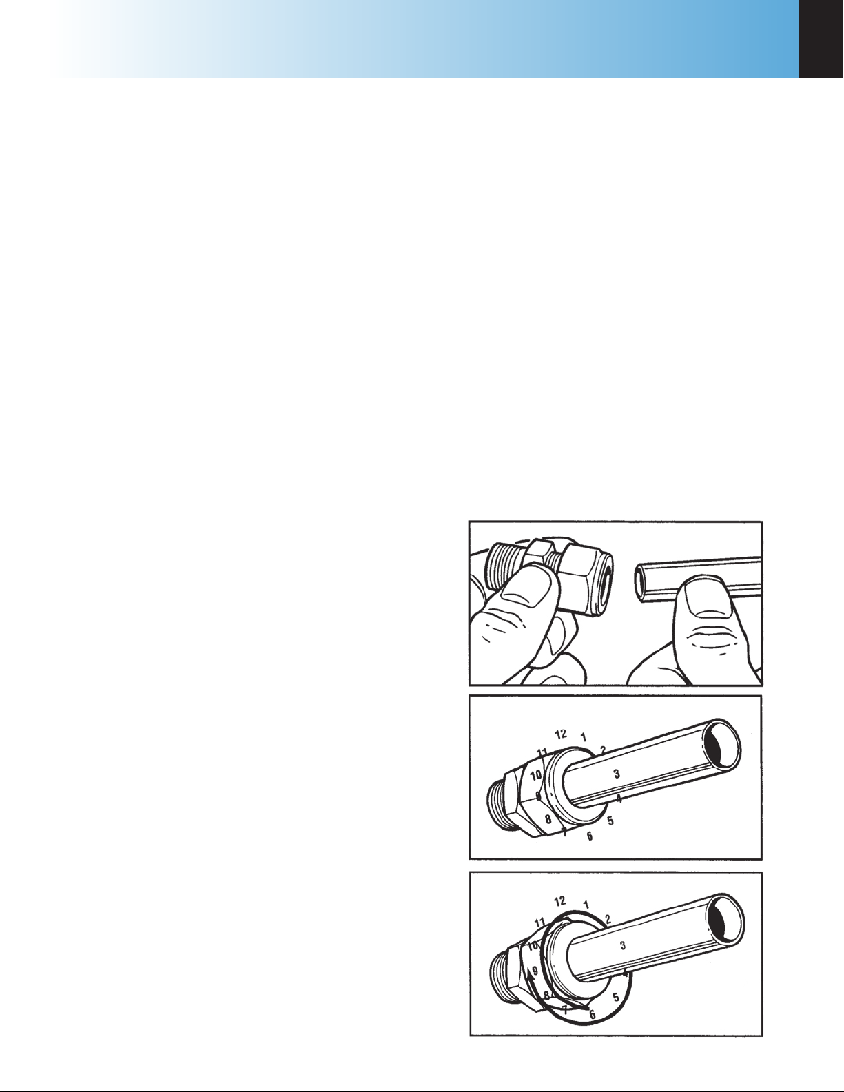
Figure 2-1
Swagelok Tube Fittings
1. Simply insert the tubing into the Swagelok Tube
Fitting. Make sure that the tubing rests firmly
on the shoulder of the fitting and that the nut is
finger-tight.
2. Before tightening the Swagelok nut, scribe the nut
at the 6 o’clock position.
3. While holding the fitting body steady with a back-
up wrench, tighten the nut 1-1/4 turns. Watch the
scribe mark, make one complete revolution and
continue to the 9 o’clock position.
4. For 3/16” and 4mm or smaller tube ttings, tight-
en the Swagelok nut 3/4 turns from nger-tight.
Retightening Swagelok Tube Fittings
Swagelok tubing connections can be disconnected
and retightened many times. The same reliable leakproof seal can be obtained every time the connection
is remade using the simple two-step procedure.
1. Insert the tubing with pre-swaged ferrules into the
fitting body until the front ferrule seats.
2. Tighten the nut by hand. Rotate the nut to the
www.parrinst.com
9
Page 12
2
Installation
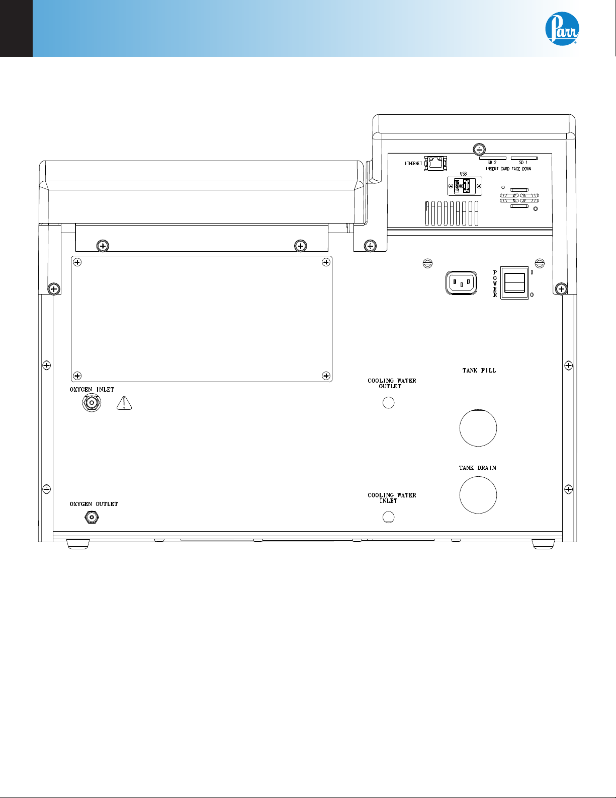
Figure 2-2
6100 Compensated Jacket Calorimeter Back Panel
Note: The Cooling Water Outlet, Cooling Water Inlet, Tank Fill and Tank Drain ports are not used on the
6100 Calorimeter.
10
Parr Instrument Company
Page 13

6100
Notes
2
www.parrinst.com
11
Page 14
3
Instrument Description
chaPter 3
Instrument Description
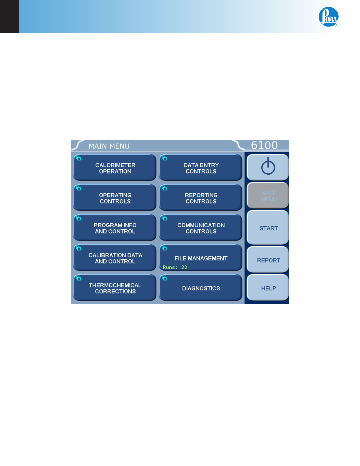
Types of Controls
All calorimeter configurations and operations are handled by a menu-driven system operated
from the bright touch screen display. The settings and controls are organized into nine main
sections or pages which comprise the MAIN MENU.
12
Note: Keys with a “double box” in the upper left hand corner lead to sub-menus.
Parr Instrument Company
Page 15

6100
Menu Keys
The controls that change the data field information in the menus will be one of the following:
1. Toggles: These data elds contain ON/OFF or YES/NO choices. Simply touching the key
2. Option Selection: These data fields contain a list of options. Touching the key on the
3. Value Entry Fields: These data fields are used to enter data into the calorimeter. Touching
4. Data Displays: Most of these keys display values that have been calculated by the calorim-
Instrument Description
on the screen toggles the choice to the other option. The current setting is displayed in the
lower right corner of the key.
screen steps the user through the available choices. The current setting is displayed in the
lower right corner of the key.
the key on the screen brings up a sub menu with a key pad or similar screen for entering
the required value. Some keys lead to multiple choices. Always clear the current value before entering a new value. Once entered the screen will revert to the previous menu and
the new value will be displayed in the lower right corner of the key.
eter and are informational only. Certain ones can be overridden by the user entering a desired value through a sub-menu. The value is displayed in the lower right corner of the key.
3
Note: Some keys will respond with an opportunity for the user to confirm the specified action to minimize accidental disruptions to the program and/or stored data.
Control Keys
There are five control keys which always appear in the right column of the primary displays.
These keys are unavailable when they are gray instead of white.
1. Escape: This key is used to go up one level in the menu structure.
2. Main Menu: This key is used to return to the main menu touch screen from anywhere in
the menu structure.
3. Start: This key is used to start a calorimeter test.
4. Report: This key is used to access the test results stored in the calorimeter, to enter ther-
mochemical corrections and to initiate a report on the display or printer.
5. Help: This key is used to access help screens related to the menu currently displayed on
the touch screen.
6. Abort: This key appears in the start key location while the test is running. Pressing this
key will abort the test in progress.
7. This key appears on the main menu only and is used to prepare the calorimeter for
turning off the power.
www.parrinst.com
13
Page 16

4
Program Installation & Control
chaPter 4
Program Installation & Control
Software Installation
The program in the 6100 Calorimeter can be extensively modified to tailor the unit to a wide variety
of operating conditions, reporting units, laboratory
techniques, available accessories and communication modes.
In addition, the calculations, thermochemical corrections and reporting modes can be modified to
conform to a number of standard test methods and
procedures.
Numerous provisions are included to permit the
use of other reagent concentrations, techniques,
combustion aids and short cuts appropriate for the
user’s work.
Note: Changes to the program are made by
use of the menu structure described in Appendix A of this manual. Any of these items
can be individually entered at any time to
revise the operating program.
Revising Default Settings
The default parameters of the 6100 Calorimeter can
be changed to guarantee that the 6100 Calorimeter,
when cold restarted, will always be in the desired
configuration before beginning a series of tests.
Users who wish to permanently revise their default
settings may do so using the following procedure:
1. Establish the operating parameters to be stored
as the user default settings.
2. Go to the Program Information and Control
Menu, User/Factory Settings, User Setup ID, and
enter the desired User Setup ID.
3. Select Save User Default Settings.
To re-load the user default setting, go to the Pro-
gram Information and Control Page, User/Factory,
Re-load User Default Settings, and YES.
Default Settings
Units are pre programmed with DEFAULT SETTINGS. See Pages 16 and 17 for a listing of the
factory default settings.
These default settings remain in effect until changed
by the user. Should the user ever wish to return to
the factory default settings, go to the Program In-
formation and Control Menu, User/Factory Settings
and Reload Factory Default Settings.
Non-volatile memory is provided to retain the date
and time; even if power is interrupted or the unit is
turned off.
14
Parr Instrument Company
Page 17

6100
Notes
4
www.parrinst.com
15
Page 18

4
Program Installation & Control
Table 4-1
Factory Default Settings
Calorimeter Operations
Operating Mode Determination
Bomb Installed/EE 1/2400.0
Operating Controls
Method of Operation Dynamic
Reporting Units BTU/lb
Use Spiking Correction OFF
“OTHER” Multiplier 4.1868
Calibrate Touchscreen
LCD Backlight Timeout(s)
LCD Backlight Intensity 70%
Print Error Messages ON
Language English
1200 s
Spike Controls
Use Spiking OFF
Heat of Combustion of Spike 6318.4
Use Fixed Spike OFF
Weight of Fixed Spike 0.0
Prompt for Spike before Weight OFF
Program Information and Controls
Date & Time Settings
Software and Hardware Info
Settings Protect OFF
User/Factory Settings
Feature Key
Bomb Type Select
User Function Setup
Cold Restart
User/Factory Settings
User Setup ID 61-1108
Reload Factory Default Settings
Reload User Default Settings
Save User Default Settings
Calibration Data & Controls
Calibration Run Limit
EE Max Std Deviation 0.0
Heat of Combustion of Standard 6318.4
Bomb Service Interval 500
Control Chart Parameters
Use Bomb 1
10
Bomb 1 Through 4
EE Value 2400.0
Protected EE Value OFF
Thermochemical Corrections Standardization
Fixed Fuse Correction ON 50
Acid Correction Fixed HNO3 10.0
Fixed Sulfur Correction ON 0.0
Heat of Formation Sulfuric Acid
Heat of Formation Nitric Acid 14.1
36.1
Determination
Fixed Fuse Correction ON 50
Acid Correction Fixed HNO3 10.0
Fixed Sulfur Correction OFF 0.0
Calculation Factors
Nitric Acid Factor 1.58
Acid Multiplier 0.0709
Sulfur Value is Percent ON
Sulfur Multiplier 0.6238
Fuse Multiplier 1.0
Use Offset Correction (ISO) OFF
Offset Value 0.0
16
Parr Instrument Company
Page 19

6100
Program Installation & Control
4
Net Heat/Dry Factors
Fixed Hydrogen OFF 0.0
Fixed Oxygen ON 0.0
Fixed Nitrogen ON 0.0
Calculate Net Heat of Combustion OFF
Fixed Moisture as Determined OFF 0.0
Fixed Moisture as Received OFF 0.0
Dry Calculation OFF
Data Entry Controls
Prompt for Bomb ID ON
Weight Entry Mode Touch Screen
Acid Entry Mode Touch Screen
Net Heat Entry Values Touch Screen
Auto Sample ID Controls ON
Sample Weight Warning above 2.0
Spike Weight Entry Mode Touch Screen
Sulfur Entry Mode Touch Screen
Moisture Entry Modes Touch Screen
Auto Preweigh Controls ON
Auto Sample ID Controls
Automatic Sample ID ON
Automatic Sample ID Increment 1
Automatic Sample ID Number 1
Auto Preweigh Controls
Automatic Preweigh ID ON
Automatic Preweigh ID Increment 1
Automatic Preweigh ID Number 1
Communication Controls
Printer Type Parr 1758
Balance Port
Network Interface
Printer Destination Local (USB)
Bar Code Port
Network Data Devices
Balance Port Communications
Balance Type Generic
Balance Port Device /dev/ttyUSB0
Customize Balance Settings
Balance Port Settings
Number of Data Bits 8
Parity None
Number of Stop Bits 1
Handshaking None
Baud Rate 9600
Data Characters from Balance 8
Data Precision 4
Transfer Timeout (seconds) 10
Balance Handler Strings
Data Logger
Data Logger OFF
Data Log Interval 10s
Data Log Destination Log File and Printer
Select Data Log Items
Data Log Format Text Format
Reporting Controls
Report Width 40
Automatic Reporting ON
Auto Report Destination Printer
Individual Printed Reports OFF
Edit Final Reports OFF
Recalculate Final Reports OFF
Use New EE Values in Recalculation OFF
www.parrinst.com
17
Page 20

5
Operating Instructions
chaPter 5
Operating Instructions
Operating the Calorimeter
All operations required to standardize the 6100 Calorimeter, or test an unknown sample, should proceed
step-wise in the following manner:
Operating the 1108P Oxygen Combustion Vessel
Detailed instructions for preparing the sample and
charging the 1108P Oxygen Combustion Vessel are
given in Operating Instructions No. 418M. Follow
these instructions carefully, giving particular attention to the precautions to be observed in charging
and handling the bomb.
Operating the Filling Connection
To fill the bomb, connect the hose to the bomb inlet
valve and push the O2 Fill button on the calorimeter
control panel. The calorimeter will then fill the bomb
to the preset pressure and release the residual
pressure in the connecting hose at the end of the
lling cycle. It will take approximately 60 seconds to
fill the bomb. During this time a countdown timer
on the O2 fill button will display the remaining fill
time. Pushing the O2 key a second time will stop the
ow of oxygen at any time. Once the display returns
to its normal reading, the user can disconnect the
coupling and proceed with the combustion test.
If the charging cycle should be started inadvertently,
it can be stopped immediately by pushing the O2 fill
key a second time.
During extended periods of inactivity, overnight
or longer, close the tank valve to prevent leakage.
When changing oxygen tanks, close the tank valve
and push the O2 FILL key to exhaust the system. Do
not use oil or combustible lubricants on this filling
system or on any devices handling oxygen under
pressure. Keep all threads, fittings, and gaskets
clean and in good condition. Replace the two
394HCJE O-rings in the slip connector if the connector fails to maintain a tight seal on the bomb inlet
valve.
The recommended filling pressure is 450 psig (3
MPa or 30 bar). This pressure is prescribed by most
of the standard bomb calorimetric test methods.
Higher or lower lling pressures can be used, but
the bomb must never be filled to more than 600
psig (40 atm).
1. Allow at least 20 minutes for the calorimeter to
warm up. The bomb parts should be wetted and
then dried in the manner used at the conclusion
of a test. This serves to wet all sealing parts as
well as leaving the bomb with the same amount
of residual water which will exist in all subsequent testing.
2. Prepare and weigh the sample to 0.0001g.
Charge the oxygen bomb as described in the
Operating the Filling Connection Section. Using
an additional bomb and bucket can increase the
throughput of the 6100 Calorimeter. With this
arrangement, the calorimeter can operate almost
continuously since the operator will be able to
empty a bomb and recharge it while a run is in
progress. A bomb and bucket for the next run will
be ready to go into the calorimeter as soon as it
is opened. Each bomb and bucket combination
will have to be standardized separately and the
proper energy equivalent for each set must be
used when calculating the heat of combustion.
3. Fill the calorimeter bucket by first taring the dry
bucket on a solution or trip balance; then add
2000 (+/- 0.5) grams of water. Distilled water is
preferred, but demineralized or tap water containing less than 250 ppm of dissolved solids
is satisfactory. The bucket water temperature
should be at or slightly below (1-2 degrees) below the room temperature. It is not necessary to
use exactly 2000 grams, but the amount selected
must be duplicated within +/- 0.5 gram for each
run. Instead of weighing the bucket, it can be
filled from an automatic pipet, or from any other
volumetric device if the repeatability of the filling
system is within +/- 0.5 mL.
To speed and simplify the bucket filling process,
and to conserve water and energy, Parr offers a
closed circuit Water Handling System (No. 6510).
This provides a water supply, cooled to the starting
temperature and held in an automatic pipet ready
for delivery in the exact amount needed to ll the
bucket, at a repeatable temperature. Instructions
for this automatic system are given in Operating
Instruction No. 454M.
18
Parr Instrument Company
Page 21

6100
Operating Instructions
5
4. Set the bucket in the calorimeter. Attach the
lifting handle to the two holes in the side of the
screw cap and partially lower the bomb in the
water. Handle the bomb carefully during this operation so that the sample will not be disturbed.
Push the two ignition lead wires into the terminal sockets on the bomb head. Orient the wires
away from the stirrer shaft so they do not become tangled in the stirring mechanism. Lower
the bomb completely into water with its feet
spanning the circular boss in the bottom of the
bucket. Remove the lifting handle and shake any
drops of water back into the bucket and check for
gas bubbles.
5. Close the calorimeter cover. This lowers the stirrer and thermistor probe into the bucket.
6. Select determination or standardization as appropriate on the Calorimeter Operation page,
by toggling the operating mode key. Press the
START key. The calorimeter will now prompt the
operator for Bomb ID number, sample ID number, sample weight and spike weight in accordance with the instructions set into the Operating Controls page.
7. The calorimeter will now take over and conduct
the test. During the time it is establishing the
initial equilibrium, it will display PREPERIOD on
the status bar. Just before it res the bomb, it
will sound a series of short beeps to warn the
user to move away from the calorimeter. Once
the bomb has been fired, the status bar will display POSTPERIOD. The calorimeter will check to
make certain that a temperature rise occurs and
will then look for the final equilibrium conditions
to be met. If it fails to meet either the initial or
final equilibrium conditions, or if it fails to detect
a temperature rise within the allotted time, the
calorimeter will terminate the test and advise the
user of the error.
one minute to avoid entrainment losses. After
all pressure has been released, unscrew the cap;
lift the head out of the cylinder and examine the
interior of the bomb for soot or other evidence
of incomplete combustion. If such evidence is
found, the test will have to be discarded. Otherwise, wash all interior surfaces of the bomb,
including the head, with a jet of distilled water
and collect the washings in a beaker.
10. Titrate the bomb washings with a standard
sodium carbonate solution using methyl orange,
red or purple indicator. A 0.0709N sodium carbonate solution is recommended for this titration to simplify the calculation. This is prepared
by dissolving 3.76 grams of Na2CO3 in the water
and diluting to one liter. NaOH or KOH solutions
of the same normality may be used.
11. Analyze the bomb washings to determine the
sulfur content of the sample if it exceeds 0.1%.
Methods for determining sulfur are discussed in
Operating Instructions No. 207M.
12. At the end of the testing period, go to the main
menu and press the key. Press YES to con-
firm System Shutdown. Turn off the calorimeter
at the power switch when prompted by the
display.
8. At the conclusion of the test, the calorimeter will
signal the user.
9. Open the cover and remove the bomb and
bucket. Remove the bomb from the bucket and
open the knurled valve knob on the bomb head
to release the residual gas pressure before attempting to remove the cap. This release should
proceed slowly over a period of not less than
www.parrinst.com
19
Page 22
5
Operating Instructions
Combustion Aids
Some samples may be difficult to ignite or they may
burn so slowly that the particles become chilled
below the ignition point before complete combustion is obtained. In such cases benzoic acid, white oil
or any other combustible material of known purity
can be mixed with the sample. Ethylene glycol,
butyl alcohol or decalin may also be used for this
purpose.
Note: It must be remembered, however, that
a combustion aid adds to the total energy
released in the bomb and the amount of
sample may have to be reduced to compensate for the added charge.
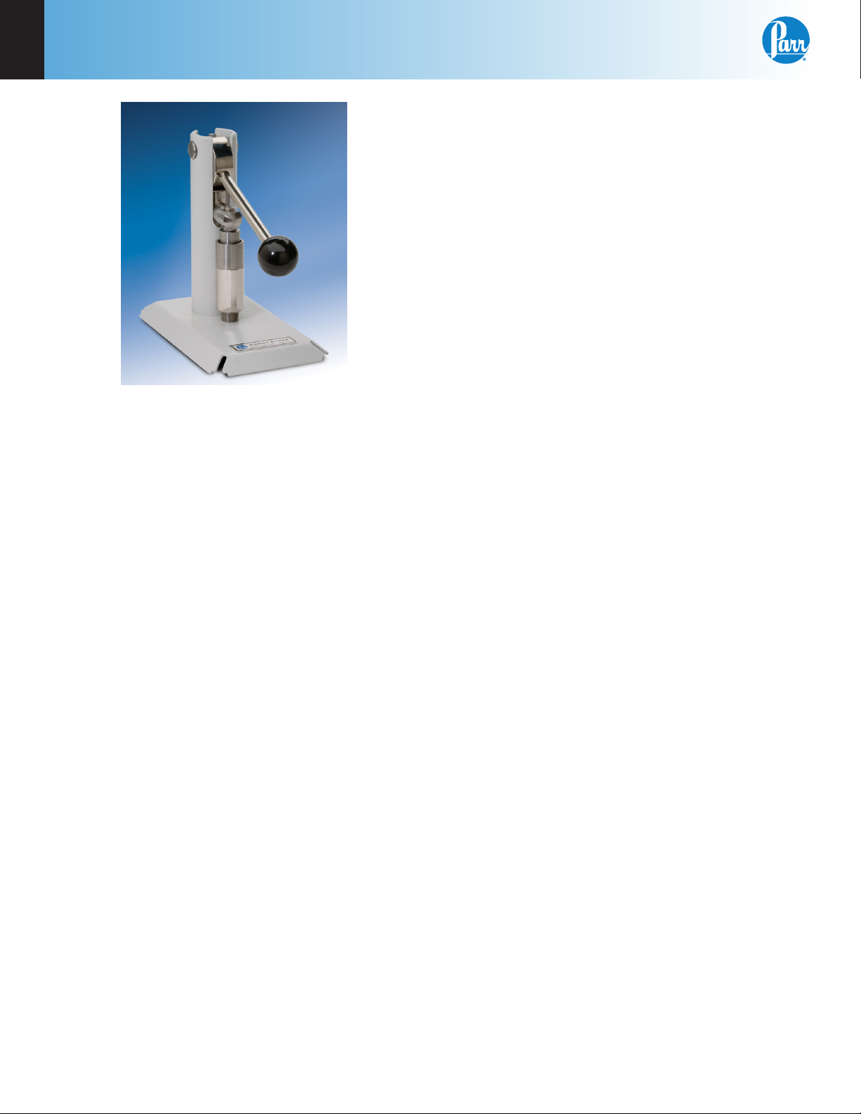
Figure 5-1
2811 Pellet Press
Samples and Sample Holders
Particle Size and Moisture Content. Solid samples
burn best in an oxygen bomb when reduced to 60
mesh, or smaller, and compressed into a pellet with
a Parr 2811 Pellet Press.
Large particles may not burn completely and small
particles are easily swept out of the capsule by
turbulent gases during rapid combustion.
Note: Particle size is important because it
influences the reaction rate. Compression into
a pellet is recommended because the pressure developed during combustion can be
reduced as much as 40% when compared to
the combustion of the material in the powder
form. In addition to controlling burn rates, the
pelletizing of samples keeps the sample in the
fuel capsule during combustion.
Materials, such as coal, burn well in the as-received
or air-dry condition, but do not burn completely dry
samples. A certain amount of moisture is desirable
in order to control the burning rate. Moisture con-
tent up to 20% can be tolerated in many cases, but
the optimum moisture is best determined by trial
combustions.
If moisture is to be added to retard the combustion
rate, drop water directly into a loose sample or onto
a pellet after the sample has been weighed. Then
let the sample stand for awhile to obtain uniform
distribution.
Also, when benzoic acid is combusted for standardization runs or for combustion aid purposes, it
should be in the form of a pellet to avoid possible
damage to the bomb which might result from rapid
combustion of the loose powder.
Oxygen Charging Pressure
The 6100 Calorimeter has been designed to operate
with an oxygen lling pressure of 30 atm. Signicant changes from this value are not recommended.
Combustion Capsules
Non-volatile samples to be tested in Parr oxygen
combustion vessels are weighed and burned in
shallow capsules measuring approximately 1” diameter and 7/16” deep. These are available in stainless
steel, fused silica, fused quartz, and platinum al-
loyed with 3-1/2% rhodium.
Stainless steel capsules (43AS) are furnished with
each calorimeter. When combusting samples that
contain metal particles such as aluminum or magnesium, the non-metallic fused silica 43A3 Capsule or
fused quartz 43A3KQ is required. When superior corrosion resistance is needed, the Platinum Rhodium
43A5 Capsule is required.
The stainless steel capsules will acquire a dull gray
nish after repeated use in an oxygen bomb due to
the formation of a hard, protective oxide lm. This
dull finish not only protects the capsule, but it also
promotes combustion and makes it easier to burn
the last traces of the sample.
20
Parr Instrument Company
Page 23
6100
Operating Instructions
5
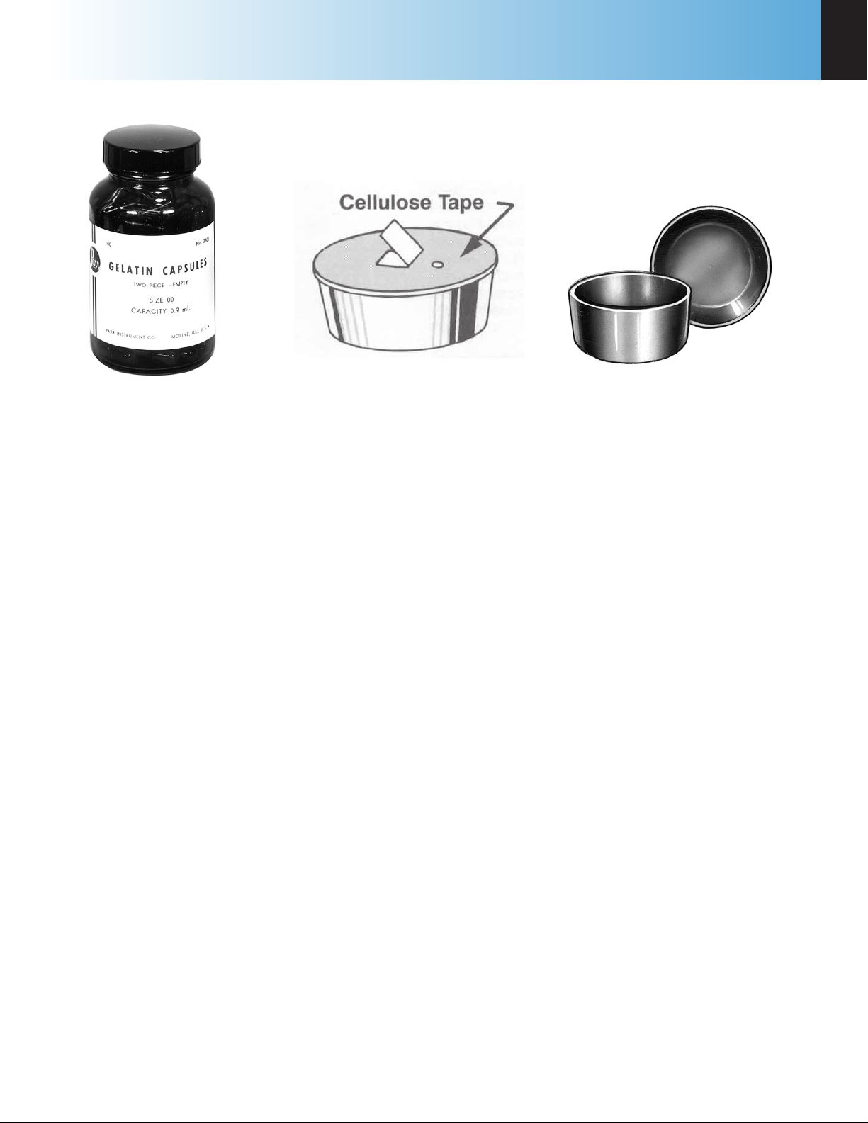
Figure 5-2
3601 Gelatin Capsules
Capsules should be monitored for wear. Do not use
the capsule if the wall or base thickness is less than
0.025”.
New capsules are heated in a muffle furnace at 500 ºC
for 24 hours to develop this protective coating
uniformly on all surfaces. This treatment should be
repeated after a capsule has been polished with an
abrasive to remove any ash or other surface depos-
its. Heating in a mufe is also a good way to destroy
any traces of carbon or combustible matter which
might remain in the capsule from a previous test.
Note: After heating, place the capsules in
a clean container and handle them only
with forceps when they are removed to be
weighed on an analytical balance.
Foodstuffs and Cellulosic Materials
Fibrous and fluffy materials generally require one
of three modes of controlling the burn rate. Fibrous
materials do not pelletize readily and generally
require either moisture content or a combustion aid
such as mineral oil to retard the burn rate and avoid
development of high pressures.
43A6 Combustion Capsule with
Figure 5-3
Adhesive Tape Seal
Figure 5-4
43AS Combustion Capsules
Coarse Samples
In most cases it may be necessary to burn coarse
samples without size reduction since grinding or
drying may introduce unwanted changes. There is
no objection to this if the coarse sample will ignite
and burn completely.
Whole wheat grains and coarse charcoal chunks are
typical of materials which will burn satisfactorily
without grinding and without additives or a special
procedure.
Corrosive Samples
The 1108P Oxygen Combustion Vessel is made of a
corrosion resistant alloy designed to withstand the
corrosive mixture of sulfuric and nitric acids produced in normal fuel testing operations. Samples
containing chlorine and particular samples containing more than 20 mg of chlorine samples with high
sulfur contents will greatly accelerate corrosion of
the bomb. An alternate 1108PCL vessel is available
constructed of an alloy selected to specifically resist
the corrosive effects of samples with high chlorine
or other halogens.
Partial drying may be necessary if the moisture content is too high to obtain ignition, but if the sample
is heat sensitive and cannot be dried, a water
soluble combustion aid such as ethylene glycol can
be added to promote ignition.
While no material will offer complete corrosion
resistance to these samples, the 1108PCL vessel
offers significantly enhanced corrosion resistance
for this service.
www.parrinst.com
21
Page 24
5
Operating Instructions
Explosives and High Energy Fuels
The 1108P and 1108PCL vessels used in the 6100
Calorimeter have been designed to provide highly
automated testing of routine samples. Materials
which release large volumes of gas which detonate
with explosive force or burn with unusually high
energy levels should not be tested with these
bombs.
Rather, they should be tested in a model 1104 High
Pressure Oxygen Combustion Vessel designed
specifically for these types of samples.
Volatile Sample Holders
Volatile samples can be handled in a Parr 43A6
Platinum Capsule with a spun rim, or in a Parr 43AS
Alloy Capsule which has a sturdy wall with a flat
top rim. These holders can be sealed with a disc of
plastic adhesive tape prepared by stretching tape
across the top of the cup and trimming the excess
with a sharp knife. The seal obtained after pressing
this disc firmly against the rim of the cup with a flat
blade will be adequate for most volatile samples.
The tape used for this purpose should be free of
chlorine and as low in sulfur as possible. Borden
Mystic Tape, No. M-169-C or 3M Transparent Tape,
No. 610, are recommended for this purpose. The 3M
Transparent Tape can be ordered through Parr, Part
No. 517A.
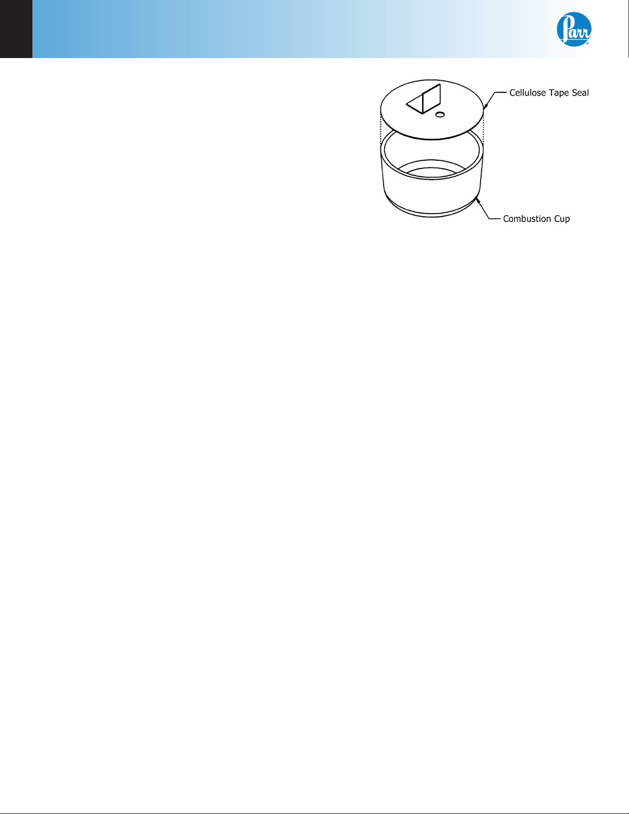
Figure 5-5
Combustion Capsule with Adhesive Tape Seal
Use the following procedure when filling and
handling any of these tape-sealed sample holders:
• Weigh the empty cup or capsule; then cover the
top with tape, trim with a knife and press the
trimmed edge firmly against the metal rim. Also
cut and attach a small flag to the disc (see Figure
5-5).
• Puncture the tape at a point below the flag, then
re-weigh the empty cup with its tape cover.
• Add the sample with a hypodermic syringe;
close the opening with the flag and re-weigh the
filled cup.
The weight of the tape disc must be determined
separately and a correction applied for any elements
in the tape which might interfere with the deter-
mination. The approximate Heat of Combustion of
the tape is 6300 cal/g. An actual amount should be
determined by running a blank test with tape alone
using a sample weighing 1.0 gram. The compensation for heat of tape may be done through the spike
option; see Spike Controls, Line 2 - Heat of Combustion of Spike.
Note: Tape should always be stored in a
sealed container to minimize changes in its
moisture and solvent content.
22
Parr Instrument Company
• Set the cup in the capsule holder and arrange
the auxiliary fuse so that it touches the center of
the tape disc.
• Just before starting the test, prick the disc with
a sharp needle to make a small opening which
is needed to prevent collapse of the disc when
pressure is applied.
• Fill the bomb with the usual oxygen charging
pressure.
• The calorimeter will fire the bomb and complete
the test in the usual manner.
Page 25

6100
Operating Instructions
5
Volatile samples are defined as one with an initial
boiling point below 180 ºC per ASTM D-2.
Low volatile samples with a high water content,
such as urine or blood, can be burned in an open
capsule by absorbing the liquid on filter paper pulp
or by adding a combustion aid, such as ethylene
glycol.
Poor Combustion
Because of the difference in combustion characteristics of the many different materials which
may be burned in an oxygen bomb, it is difcult to
give specific directions which will assure complete
combustions for all samples.
The following fundamental conditions should be
considered when burning samples:
• Some part of the sample must be heated to its
ignition temperature to start the combustion
and, in burning, it must liberate sufficient heat
to support its own combustion regardless of the
chilling effect of the adjacent metal parts.
• Insufficient space between the combustion cup
and the bottom of the bomb. The bottom of the
cup should always be at least one-half inch above
the bottom of the bomb or above the liquid level
in the bomb to prevent thermal quenching.
• Excessive moisture or non-combustible material
in the sample. If the moisture, ash and other non
combustible material in the sample amounts to
approximately 20% or more of the charge, it may
be difficult to obtain complete combustion. This
condition can be remedied by adding a small
amount of benzoic acid or other combustion aid.
• The combustion must produce sufficient tur-
bulence within the bomb to bring oxygen into
the fuel cup for burning the last traces of the
sample.
• Loose or powdery condition of the sample which
will permit unburned particles to be ejected during a violent combustion.
• The use of a sample containing coarse particles
which will not burn readily. Coal particles which
are too large to pass a 60 mesh screen may not
burn completely.
• The use of a sample pellet which has been made
too hard or too soft. Either condition can cause
spalling and the ejection of unburned fragments.
www.parrinst.com
23
Page 26

6
Corrections & Final Reports
chaPter 6
Corrections & Final Reports
Entering Corrections and Obtaining the Final Report
Final reports for each test can be obtained whenever
the operator is prepared to enter any required corrections for fuse, acid and sulfur.
When entering corrections, the user can choose
either of two methods. These are:
• Manual Entry
• Fixed Corrections
Program and Installation, Chapter 4. provides the
default settings used to setup the method preferred
by the user.
Refer to the Reporting Instructions, Chapter 7, for the
steps necessary to initiate a report from the controller.
Manual Entry
During the reporting process, the controller will
prompt the user to enter the following values:
Fuse Correction: Key in the Fuse Wire Correction
and press the ENTER key. The default setting for this
value is to be entered in calories. The fuse correction
has two components and these are explained in
Appendix B.
If xed values for fuse, acid and sulfur are turned
OFF on the Thermochemical Corrections Page, then
the user must manually enter the values at the
prompt.
If the Spiking Correction is used, a spiking correction
must be entered before obtaining a Final Report.
After the last entry has been made, the calorimeter
will automatically produce a Final Report.
If values for these corrections are not available,
the operator can use the SKIP key to bypass any
of the corrections; however, a Final Report will not
be printed until an entry is made for fuse, acid and
sulfur.
Fixed Corrections
In many cases, xed values for fuse and acid can be
used without introducing a significant error since
the corrections are both relatively small and constant.
Fixed sulfur corrections can also be used whenever
a series of samples will be tested with a reasonably
constant sulfur content.
Details for applying xed corrections are found in
Appendix B, Thermochemical Calculations.
Acid Correction: Key in the Acid Correction and
press the ENTER key. The default setting for this
value is to be entered in milliliters of standard alkali
required to titrate total acid or calories.
Sulfur Correction: Key in the Sulfur Correction
and press the ENTER key. The default setting for
this value is to be entered as percent sulfur in the
sample.
24
Parr Instrument Company
Any value set-up as a xed correction will be automatically applied and the controller will not prompt
the user for this value.
Page 27

6100
Notes
6
www.parrinst.com
25
Page 28

7
Reporting Instructions
chaPter 7
Reporting Instructions
Report Option Section
The 6100 Calorimeter can transmit its stored test
data in either of two ways. The REPORT DESTINA-
TION key on the Reporting Controls Page toggles
the report destination between the display and
an optional printer connected to the USB port of
the calorimeter. This page also selects the type of
reports that are generated automatically by the
calorimeter.
Report Generation
There are two kinds of calorimeter reports: Preliminary and Final.
Select From List: This key displays the stored
results specified with the following two keys:
Preliminary Reports are generated at the conclusion
of a test. They will not contain the final thermochemical corrections for sulfur, fuse, or acid. They are
intended to confirm to the operator that the results
of the test fell within the expected range.
Final reports are generated once all of the thermochemical corrections have been entered into the file.
If xed corrections are used for all of the thermochemical corrections a preliminary report will not be
generated.
Thermochemical corrections are entered by using
the following steps to select and edit preliminary
reports.
Test results are stored as files using the sample
ID number as the file name. A listing of the stored
results is accessed by pressing the REPORT command key. The REPORT command key brings up a
sub-menu on which the operator specifies.
Run Data Type: This key enables the operator to display only determination runs, only
standardization runs and all runs. (The choice
of solution data type is not applicable to this
calorimeter.)
Run Data Status: This key enables the operator to display only preliminary reports, only final reports, both preliminary and final reports,
only pre weighed sample reports or all stored
reports.
Prompt For Final Values: When turned on, the
controller will prompt the operator to enter
any missing corrections for fuse, sulfur and
acid in any selected preliminary reports. When
turned off preliminary reports will be displayed
as entered.
26
Parr Instrument Company
Page 29

6100
The displayed files can be sorted by sample ID number, by type, by status or by date of test by simply
touching the appropriate column.
Individual files can be chosen by highlighting them
using the up and down arrow keys to move the
cursor. Press the SELECT key to actually enter the
selection. Once selected the highlight will turn
from dark blue to light blue. A series of tests can be
selected by scrolling through the list and selecting
individual files.
The double up and down keys will jump the cursor
to the top or bottom of the current display.
If a range of tests is to be selected, select the first
test in the series, scroll the selection bar to the last
test in the series and press EXTEND SEL to select
the series.
The DESEL ALL key is used to cancel the current
selection of files.
To bring the selected report or series of reports to
the display, press the DISPLAY key. To send the re-
ports to the printer press the PRINT key.
Reporting Instructions
Net Heat of Combustion
To have the Net Heat of Combustion print as part
of preliminary and final reports, go to the Thermo-
chemical Corrections Page, Net Heat/Dry Factors,
and turn ON Calculate Net Heat of Combustion. Dur-
ing the reporting process, the controller will prompt
for the hydrogen (H) value.
7
The EDIT key brings up a sub-menu which enables
the operator to edit any of the data in the report or
add thermochemical corrections to convert preliminary reports to final reports. Final reports can only
be edited if EDIT FINAL reports on the reporting
control page is turned on.
www.parrinst.com
27
Page 30

8
File Management
chaPter 8
File Management
The 6100 Calorimeter will hold data for 1000 tests in its memory. These tests may be
pre weights, preliminary or final reports for either standardization or determination
runs. Once the memory of the controller is filled, the controller will not start a new
analysis until the user clears some of the memory.
Clearing Memory
The FILE MANAGEMENT key on the main menu
leads to the file management sub-menu. The RUN
DATA FILE MANAGER key leads to a listing of the
files.
• Single files can be deleted by highlighting the
file and pressing the DELETE key. The controller
will then ask the user to confirm that this file is
to be deleted.
• A series of files can be deleted by selecting the
first file in the series and then the last file in
the series using the EXTEND SEL key and then
pressing the DELETE key.
Removable SD Memory Cards
The controller of the 6100 Calorimeter can accept SD
memory cards. These cards can be used to:
• Copy test file data for transfer to a computer.
• Copy user settings for back up.
• Reload user settings to the controller.
• Restore or update the controller’s operating
system.
SD memory cards are inserted into one of the slots
on the back of the control section of the calorimeter.
Keys are provided on the FILE MANAGEMENT submenu to initiate each of the above three actions with
the exception of restoring or updating the controller’s operating system.
28
Parr Instrument Company
Page 31

6100
Notes
8
www.parrinst.com
29
Page 32

9
Maintenance & Troubleshooting
chaPter 9
Maintenance & Troubleshooting
Oxygen Bomb
Under normal usage the 1108P Parr Oxygen Combustion Vessel will give long service if handled with
reasonable care. However, the user must remember
these bombs are continually subjected to high temperatures and pressures that apply heavy stresses
to the sealing mechanism. The mechanical condition
of the bomb must therefore be watched carefully
and any signs of weakness or deterioration should
be replaced before they fail.
It is recommended the 1108P Oxygen Combustion
Vessel have O-rings and valve seats replaced after
6 months, 500 firings or at more frequent intervals
if the bomb has been subject to heavy usage or if it
Parr Part No. Description Type Ratings
139E23 Lines Protective Fuses Fast-Acting 15 Amps, 250Vac
shows any evidence of damage. Detailed information can be found in Manual 418M supplied as a
part of this manual. This 1108P Oxygen Combustion
Vessel is the only part of the calorimeter system that
requires routine maintenance. All other problems
will require diagnosis and parts replacement.
Fuses
The replacement of protective fuses for the 6100
Calorimeter should be performed by qualified
personnel.
Note: Check the labels on the instrument for
correct fuse rating.
Caution!
For continued protection against possible hazard, replace fuses with same type and rating of fuse.
30
Parr Instrument Company
Page 33

6100
6100 Calorimeter Error List
The calorimeter will run a number of diagnostic checks upon itself and will advise the operator if it detects any
error conditions. Most of these errors and reports will be self-explanatory. The following list contains errors
that are not necessarily self-evident and suggestions for correcting the error condition.
Maintenance & Troubleshooting
9
A Misfire Condition Has Been Detected
This error will be generated in the event the total
temperature rise fails to exceed 0.5 °C after the rst
minute of the post-period.
A Preperiod Timeout Has Occurred
The calorimeter has failed to establish an acceptable
initial temperature, prior to firing the bomb, within
the time allowed. Possible causes for this error are
listed below:
• A bomb leak
• Poor bucket stirring
• Metal to metal contact between the bucket and
the jacket
• Lid not tight
• Foam seal has deteriorated
• Starting bucket temperature is too low or too
high
• Unstable room temperature
A Postperiod Timeout has Occurred
The calorimeter has failed to establish an acceptable
final temperature within the time allowed. Possible
causes for this error are listed below:
• A bomb leak
• Poor bucket stirring
• Unstable room temperature
There Is A Problem With The Bucket Thermistor
Possible electrical open or short. These errors will
result if the temperature probe response is not within
the expected range. Probe substitution can be useful
in determining the cause of the problem (probe or
electronics). The valid working range of the probe
resistance is 1000 to 5000 ohms.
There Is A Problem With The Jacket Thermistor
Possible electrical open or short. These errors will
result if the temperature probe response is not within
the expected range. Probe substitution can be useful
in determining the cause of the problem (probe or
electronics). The valid working range of the probe
resistance is 1000 to 5000 ohms.
• Check connection to board
• Check quick disconnect between cables
• Replace probe
• Room temperature is below 10 °C (50 °F)
A/D Initialization Failed
Shortly after power is applied to the calorimeter
controller and the operating system has started, the
CPU attempts to read the unique IO board calibration information from the IO board. If the IO board is
not connected to the CPU, or the information on the
board is not valid, this error will be issued.
Bomb ID – Has Been Fired – Times Which Exceeds The Bomb
Service Interval
The calorimeter controller keeps track of how many
times the bomb has been red. When this count exceeds a preset limit (usually 500) this message will be
issued each time the bomb is used for a test. Perform
bomb maintenance and reset the bomb fire count on
the Calibration Data and Control page for the appropriate bomb number.
You Have Exceeded The Run Data File Limit (1000 Files)
The memory set aside for test runs has been filled.
Use the memory management techniques to clear
out non-current tests. See page 31.
Bomb EE Standard Deviation Warning
The relative standard deviation for the calibration
runs in memory for the indicated bomb exceeds the
preset limit.
• Check connection to board
• Check quick disconnect between cables
• Replace probe
• Room temperature is below 10 °C (50 °F)
Sample Weight Warning
The entered sample mass exceeds the value entered
via the [Sample Weight Warning Above] key on the
Data Entry Controls page. This warning threshold is
normally 2 grams.
www.parrinst.com
31
Page 34

A
Menu Operating Instructions
aPPendix a
Menu Operating Instructions
When the START key is pressed, the calorimeter will
prompt the user for the Sample ID, sample weight,
Bomb ID and spike weight as programmed by the
user in the Operating Controls and Data Entry Control menu screens.
The settings and controls are organized into ten
main sections or pages which comprise the Main
Menu. This appendix describes all pages of the
menu-based operating system of the 6100 Calorimeter.
Operating Mode: Sets the operating mode by toggling between standardization and determination.
Bomb/EE: Used to identify the bomb presently
installed in the calorimeter and its EE value.
Start Preweigh: This key is used to start the sample
preweigh process. The user is presented with or
prompted for a sample ID. Next, the user is asked to
key in the associated sample mass or alternatively
the mass is retrieved from a connected balance.
O2 Fill: This key is used to activate the oxygen lling
system used to fill the bomb. Pressing this same key
while the bomb is filling will abort the process.
Note: Keys which make global changes to
the setup of the calorimeter contain a YES or
NO response to make certain that the user
wishes to proceed. This two step entry is
intended to prevent inadvertent global program changes.
Calorimeter Operation Menu
The calorimeter will normally be operated from
the Calorimeter Operating Page, although tests can
always be started from any menu page.
Temperature Graph: Press this key to view the
Temperature vs. Time Plot Screen.
Temperature vs. Time Plot Screen
Setup: Press this key to access the Temperature
Plot Setup Menu, which has many keys that
permit the user to fully customize both the x
(time) axis and the scaling of the y axis.
32
Parr Instrument Company
Page 35

6100
Menu Operating Instructions
A
Temperature Plot Setup Menu
Enable Bucket: Toggles ON/OFF.
Bucket Autoscale: Toggles ON/OFF.
Enable Jacket: Toggles ON/OFF.
Jacket Autoscale: Toggles ON/OFF.
Time Mode: Toggles between Autoscale, Win-
dow, and Range.
Bucket Plot Symbol: Toggles between:
» No Point
» Small Dot
» Round
» Square
» Up Triangle
» Down Triangle
» Diamond
Bucket Min Value: Press this key to access its
numeric dialog box to set a minimum bucket
value.
Jacket Min Value: Press this key to access its
numeric dialog box to set a minimum jacket
value.
Time Window: Sets the time scale for the X-
axis.
Time Units: Toggles between minutes and
seconds.
Bucket Plot Color: Toggles between:
» Red
» Green
» Yellow
» Blue
» Magenta
» Cyan
» White
» Black
Bucket Max Value: Press this key to access its
numeric dialog box to set a maximum bucket
value.
Jacket Plot Color: Toggles between
(same as Bucket Plot Color, above).
Jacket Max Value: Press this key to access its
numeric dialog box to set a maximum jacket
value.
Time Minimum: Press this key to access its
numeric dialog box to set the least amount of
time for the run.
Time Maximum: Press this key to access its
numeric dialog box to set the greatest amount
of time for the run.
Jacket Plot Symbol: Toggles between (same as
Bucket Plot Symbol, above).
www.parrinst.com
33
Page 36

A
Menu Operating Instructions
Operating Controls Menu
Method of Operation: Offers an operating mode of
either dynamic or equilibrium. In most cases, the
dynamic mode with its curve matching capability
will save approximately 3-4 minutes per test and will
produce the same operating precision as the slower
equilibrium mode.
Reporting Units: Toggles between BTU/lb, cal/g, J/
kg. Other, and MJ/kg. A user selected set of reporting units may be programmed by selecting “Other”.
Spike Correction: This key accesses sub-menu,
Spike Controls. Spiking is the material addition,
such as benzoic acid or mineral oil, to samples
which are difficult to burn in order to drive the
combustion to completion.
Spiking Correction
Use Spiking: When set to ON, the calorimeter
will prompt for the weight of the spike added
and will compensate for the heat of combustion in the calculations.
Heat of Combustion of Spike: The heat of
combustion of spike is entered on sub-menu
keyboard in cal/g.
Use Fixed Spike: When set to ON, a constant
amount of spike is to be added to each test.
Weight of Fixed Spike: The weight of the fixed
spike is entered on a sub-menu keyboard.
Prompt for Spike before Weight: When set to
ON, the calorimeter will prompt the user for
the weight of the spike and the weight of the
sample. Normally the calorimeter will prompt
the user for the weight of the sample and then
the weight of the spike.
Note: The precision of tests with fixed spikes
can be no better than the repeatability of the
spike weight.
Other Multiplier: This button allows the user to
enter a final multiplier that is used when the report-
ing units are set as “Other”.
Calibrate Touchscreen: This key prompts the user
to touch the screen at predefined points in order to
facilitate touchscreen calibration.
LCD Backlight Time Out: The unit is equipped with
an automatic circuit to shut-off the backlight when it
is not being used. The back light will shut-off if there
is no keyboard activity for the number of seconds
entered. Pressing any key will automatically turn the
back lighting ON. A setting of 0 will keep the backlight ON at all times.
34
LCD Backlight Intensity: This key accesses a sub-
menu with a slide control which adjusts the contrast
on the LCD display for optimum viewing.
Print Error Messages: When turned ON, all error
messages will be printed on the printer as well as
displayed on the screen.
Language: Steps the calorimeter through the installed operating languages.
Parr Instrument Company
Page 37

6100
Menu Operating Instructions
A
Program Information and Control Menu
Date & Time: Accesses a sub-menu to set the current date and time.
Date: Displays current date and accesses
sub-menu on which date is set in (YY/MM/DD)
format.
Time: Displays current time and accesses sub-
menu on which time is set in (HH:MM) format.
Time Zone: Displays the selected time zone
in relation to Greenwich Mean Time. Pressing
this key will step through the time zones and
automatically adjust the time setting.
Volume Level Adjust: Opens a window with a slide
adjustment to set the volume of the key clicks and
alarms of the calorimeter. Default is 85%.
Software and Hardware Info: This screen displays
important information such as the main software
version, I/O board hardware information, CPU type,
IO firmware revision, and Controller IP address.
Settings Protect: Provides protection for the program options and settings on the menus. If this is
turned ON, the user will be warned that enumeration keys are locked when a key is pressed. Enumer-
ation Keys either toggle a value (ON/OFF) or select
from a predefined list. This feature is used primarily
to protect the instrument settings from accidental
changes if one were to inadvertently touch or bump
up against the touch screen.
User/Factory Settings: This key leads to a submenu that allows the user to save or recall user
defined instrument settings. Additionally, factory
pre installed settings supporting different bombs or
special operating modes can also be recalled.
User/Factory Settings
User Setup ID: Used to enter a unique identifier for recalling user settings.
Reload Factory Default Settings: Used to erase
all of the settings and restore the factory default settings.
Reload User Default Settings: Used to restore
the last saved user’s setup should the program
in the instrument be corrupted for any reason.
Save User Default Settings: Used to record the
setup to the memory once the user has configured the instrument to their operating requirements.
Compare Settings With Factory Defaults: This
button will bring up a screen that will show the
differences in the current settings of the calorimeter with the factory defaults.
Feature Key: Unique Feature Keys obtained from
Parr allow the user to access capabilities on the
instrument such as bar code interfacing or remote
operation of the calorimeter, or Samba Server.
Bomb Type Select: This key toggles through the
different bomb models available for the calorimeter.
When the user chooses a bomb, the instrument
must be re-booted to load the correct version of the
software.
www.parrinst.com
35
Page 38

A
Menu Operating Instructions
User Function Setup: This key leads to sub menus
that support the conguration of ve factory/user
definable function keys. The function keys are accessible from the Diagnostics page.
Cold Restart: This is essentially the same as cycling
power on the unit. All valid test data will be retained
during this cold restart procedure.
Calibration and Data Controls Menu
Calibration Run Limit: Displays the maximum
number of runs that will be included in determining
the EE value of a bomb and bucket combination and
accesses the sub-menu on which this limit is set.
Most test methods suggest 10 tests. Tests in excess
of the most recent ones used are still available but
are not used in the calculation of the EE value. For
example if 11 standardization tests have been run, the
calorimeter will only use the most recent 10. The 11th
is still stored in the memory and is available for view
or printing.
EE Max Standard Deviation: Displays the maximum
relative standard deviation in percent that will be permitted for any EE value calculated by the calorimeter
and accesses the sub-menu on which this limit is set.
If this value is exceeded, the user will be warned to
take corrective action before proceeding with testing.
This calorimeter is capable of achieving a value of
0.33 or better for 10 tests. A setting of zero disables
this check.
Heat of Combustion of Standard: Displays the heat
of combustion in calories per gram for the material
used to standardize the calorimeter and accesses the
sub-menu on which this value is set. For benzoic acid,
this value is 6318.4 calories per gram.
Bomb Service Interval: Displays the maximum
number of times a bomb may be fired before it is
flagged as due for service and accesses the submenu on which this limit is set. Parr recommends 500
firings for this service interval.
Control Chart Parameters: A control chart is a graphical tool which can assist the user in determining
whether or not their process is in control. Many
standard methods will dictate that a reference sample
be measured periodically and the results plotted on
a graph. Limits for acceptable values are defined and
the process is assumed to be in control as long as
the results stay within these limits. Since results are
expected to scatter with a normal distribution within
established limits, systematic trends or patterns in
the data plots may also be an early warning of problems.
Charted Value: Toggles the charted value be-
tween the HOC Standard (Heat Of Combustion
of Standard) and Energy Equivalent.
Process Sigma: In relation to calorimetry, sigma is used as the classification of the instrument. The higher the process sigma the higher
the limits for acceptable values for precision
control.
Note: The 6100 is a .2 Process Sigma calorimeter.
Temp. Rise High Warning: Sets a limit for the
temperature rise during a test. If the tempera-
ture rise exceeds the limit the user will be
warned.
Temp. Rise Low Warning: Sets a lower limit
warning for the temperature rise during a test.
If the temperature rise is lower than this setting the user will be warned.
Use Bomb: Displays the bomb number of the bomb
currently installed in the calorimeter and toggles
through the four possible bomb numbers. The left
and right arrow keys are used to toggle through
the bomb identification numbers available for each
bomb.
Bomb 1 - Bomb 4: Leads to sub-menus for Bomb
1 - Bomb 4. Displays standardization information
for bomb and bucket combinations. While only one
bomb and bucket is installed in the calorimeter at a
time, a spare may be used for servicing and for more
rapid turn-around. The respective EE values for each
bomb can be stored in memory.
36
Parr Instrument Company
Page 39

6100
Menu Operating Instructions
A
Note: For rapid turn around between tests,
user may wish to use two bombs. Each bomb
should be assigned a bomb number. Set
prompt for bomb ID to “ON”.
Bomb 1
EE Value: Displays the calculated EE value for the
corresponding Bomb 1.
Manual EE Entry: This key allows the user to
manually enter an EE or calibration factor for a
given calorimeter ID or bomb head. If an EE value
is manually entered, it is necessary to turn the
Protect EE Value ON in order to prevent this value
from being overwritten by an automatic update.
Print Standardization Runs: Will print all of the
tests that have been incorporated into the calculated EE value. This will be helpful in evaluating a
series of tests which fail to produce a satisfactory
EE value and relative standard deviation.
Reset Bomb Fire Count: After bomb service, press
this button to reset the fire count to zero
Control Chart Plot: Displays the current standardization runs being used to calculate the Bomb EE
Value. The display will either chart the value of
the Heat of Combustion (HOC) of the Standard
or the Energy Equivalent (EE) depending on the
selection on the Control Chart Parameters menu
(see Calibration Data and Controls menu).
You can display the information used for each test by
selecting the appropriate green dot.
Number of Runs: Displays how many runs have
been used to determine the EE value.
Relative Standard Deviation: Displays the relative standard deviation for the series of tests
used to determine the current EE value in percent
of the EE value.
Bomb Fire Count: Displays the current bomb
firing count or the number of times the bomb
has been fired since it was last serviced. When
this count matches the limit set by Bomb Service
Interval, the user will be informed that the bomb
is ready to be service.
Name: Enables the operator to assign a unique
alpha-numeric label for the bomb ID. The ID can
be up to 8 characters.
Protect EE Value: When set to ON, protects the EE
value iwf the user does not wish to have the calorimeter automatically update its own EE value.
Update Statistics: This key will cause the EE
value for this bomb ID to be updated using the
most recent standardization runs; if the EE value
is not protected. (The number of standardization
runs used is equal to the value entered into the
Calibration Data and Controls Menu under Calibration Run Limit. If less runs are available than
the number specified, all runs will be used.)
Bomb Control Chart
Bomb 2: Accesses sub-menu, Bomb 2. Provides the
same controls as described for Bomb 1.
Bomb 3: Accesses sub-menu, Bomb 3. Provides the
same controls as described for Bomb 1.
Bomb 4: Accesses sub-menu, Bomb 4. Provides the
same controls as described for Bomb 1.
www.parrinst.com
37
Page 40

A
Menu Operating Instructions
Thermochemical Calculations Menu
Standardization Correction
Fixed Fuse Correction: Displays both the ON/OFF of
the xed fuse corrections for standardization runs
and the value of the correction. This key toggles
the correction ON/OFF and accesses a sub-menu
on which the value is set. An appropriate xed fuse
value is 50 calories.
Acid Correction: Press this key on the LEFT side
to toggle between Fixed HNO3, Calculated HNO3,
Entered Total, Entered HNO3, and Fixed Total for the
acid correction for determination runs. Press it on
the RIGHT side to access the Acid Correction numeric dialog box on which the value can be set.
the RIGHT side to access the Acid Correction numeric dialog box on which the value can be set.
Fixed Sulfur Correction: Displays both the ON/OFF
of the xed sulfur corrections for determination runs
and the value of the correction. This key toggles the
correction ON/OFF and accesses a sub-menu on
which the value is set.
Note: When fixed corrections are turned ON,
the value in the specified field will be used
in both the preliminary and final reports. The
calorimeter will not prompt for actual corrections. If all corrections are fixed, a preliminary report will not print, rather only a final
report will be generated. If values for these
corrections are entered into these lines, and
the toggle is set to OFF, then the fixed value
will be used in the preliminary report, but not
in the final report.
Calculation Factors: Accesses the Calculation Factors sub-menu, which provides for setting a number
of options for the way the thermochemical corrections are applied.
Calculation Factors
Fixed Sulfur Correction: Displays both the ON/OFF
of the xed sulfur corrections for standardization
runs and the value of the correction. This key toggles
the correction ON/OFF and accesses a sub-menu on
which the value is set. When benzoic acid is used as
the calibrant, a xed sulfur value of zero should be
used.
Determination Correction
Fixed Fuse Correction: Displays both the ON/OFF
of the xed fuse corrections for determination runs
and the value of the correction. This key toggles the
correction ON/OFF and accesses a sub-menu on
which the value is set.
Acid Correction: Press this key on the LEFT side
to toggle between Fixed HNO3, Calculated HNO3,
Entered Total, Entered HNO3, and Fixed Total for the
acid correction for determination runs. Press it on
38
Parr Instrument Company
Nitric Acid Factor: The default is 1.58 calories
per 1000 calories of released energy.
Acid Multiplier: This multiplier is the normality
of the sodium carbonate used during the acid
correction titration. The default value of 0.0709
allows for direct entry of the acid correction
in calories. If the bomb rinses are titrated in
order to determine the acid correction, press
this key to display the Acid Multiplier numeric
Page 41

6100
Menu Operating Instructions
A
dialog box, where you can change the multiplier to represent the concentration of the base
(equivalents/L) or normality used for titration.
If this is the case, the acid correction is entered
as milliliters of base used to titrate the bomb
rinses.
Sulfur Value is Percent: When set to ON, the
sulfur value is being entered as weight percent
sulfur. If another system is to be used, this
must be turned OFF and the sulfur multiplier
set accordingly.
Sulfur Multiplier: Values entered by the user to
be used for the sulfur correction are multiplied
by this value to get the product into units of
milliequivalents. The default number (0.6238)
requires that the sulfur value be entered in
weight percent.
Fuse Multiplier: The fuse corrections represent the number of calories liberated by the
burning fuse wire used to ignite the sample. If
another measurement is used, the correction
factor must be entered here. Press this key to
access the Fuse Multiplier numeric dialog box
and enter this multiplier value.
Net Heat/Dry Factors: Accesses the Net Heat/Dry
Factors sub-menu, which provides for setting the net
heat of combustion and Dry Factors Thermochemical
Corrections.
Net Heat/Dry Heat Factors
Fixed Hydrogen: Press the LEFT side to toggle
this setting ON/OFF. Press the RIGHT side to
display the Fixed Hydrogen numeric dialog
box and change its value.
Use Offset Correction (ISO): The thermochemical calculations used for treatment of nitric
acid and sulfuric acid corrections in the ISO
and B. S. methods require an offset correction to compensate for the back titration that
is made. To use these calculations, toggle this
to ON and enter the appropriate value as the
offset value.
Offset Value: The value used when Offset
Correction is turned ON. Press this key to ac-
cess the Offset Value numeric dialog box and
change its value.
Heat of Formation Sulfuric Acid: Different
methods use different values for the heat of
formation of sulfuric acid. The value can be set
to match the specific method being followed.
Default = 36.1.
Heat of Formation Nitric Acid: Different
methods use different values for the heat of
formation of nitric acid. The value can be set
to match the specific method being followed.
Default = 14.1.
Fixed Oxygen: ON/OFF and value entry.
Fixed Nitrogen: ON/OFF and value entry.
Calculate Net Heat of Combustion: ON/OFF.
Turn On to have the calorimeter calculate the
net heat of combustion.
Fixed Moisture as Determined: Press the LEFT
side to toggle ON or OFF whether to use the
entered moisture correction. Press the RIGHT
side to access the Fixed Moisture as Determined numeric dialog box and set the value.
Units are weight %.
Fixed Moisture as Received: Press the LEFT
side to toggle ON or OFF whether to use the
entered moisture correction. Press the RIGHT
side to access the Fixed Moisture as Received
numeric dialog box and set the value. Units
are weight %.
Dry Calculation: Toggles the dry calculation
ON or OFF.
www.parrinst.com
39
Page 42

A
Menu Operating Instructions
Data Entry Controls Menu
Prompt for Bomb ID: In the ON position the controller will prompt for a Bomb ID (1-4) when a test is
started.
Weight Entry Mode: This key steps through the
options for entering sample weights either manually
through the touch screen, network or through the
balance (USB) port.
Hydrogen Entry Mode: This key steps through
the options for entering hydrogen content for
calculating the net heat of combustion either
manually through the touch screen or automatically through the balance (USB) port.
Oxygen Entry Mode: This key steps through
the options for entering oxygen content for
calculating the net heat of combustion either
manually through the touch screen or automatically through the balance (USB) port.
Nitrogen Entry Mode: This key steps through
the options for entering nitrogen content for
calculating the net heat of combustion either
manually through the touch screen or automatically through the balance (USB) port.
Automatic Sample ID Controls: Accesses sub-menu
for controlling the automatic assignment of sample
identification numbers.
Auto Sample ID Controls
Acid Entry Mode: This key steps through the options for entering acid correction value either
manually through the touch screen or automatically
through the balance (USB) port.
Net Heat Entry Modes: This key accesses a menu
listing options for entering hydrogen, oxygen, and
nitrogen content for calculating the net heat of combustion either manually through the touch screen or
automatically through the balance (USB) port.
Net Heat Data Entry Controls
Automatic Sample ID: When set to ON will
automatically assign sample identification
numbers in accordance with instructions set in
the other two keys on this menu.
Auto Sample ID Prefix: An entry here will be
used as a prefix for all sample IDs.
Next Auto Sample ID Number: Establishes the
initial sample number for a series of tests and
then shows the next sample ID which will be
assigned.
40
Auto Sample ID Increment: Establishes the
increment between sample numbers.
Parr Instrument Company
Page 43

6100
Menu Operating Instructions
A
Sample Weight – Warning Above: This key displays
and leads to a sub-menu used to set the maximum
allowable sample weight (including spike) in grams.
A warning will be given if sample weights above
this value are entered.
Spike Weight Entry Mode: This key steps through
the options for entering spike weights either manually through the touch screen, automatically through
the balance (USB) port or through a network.
Sulfur Entry Mode: This key toggles steps through
the options for entering sulfur correction value
either manually through the touch screen or through
the balance (USB) port.
Moisture Entry Mode: This key steps through the
options for entering the moisture percentage whether manually through the touch screen or automatically through the balance (USB) port.
Moisture Data Entry Controls
Auto Preweigh ID Controls: Accesses sub-menu,
used to automatically assign sample identification
numbers when a series of samples are pre weighed
ahead of the time they are actually tested.
Auto Preweigh Controls
Automatic Preweigh ID: ON/OFF toggle for
this feature.
Moisture as Determined Entry Mode: This
key steps through the options for entering the
moisture as determined correction value either
manually or through the touch screen or automatically through the balance (USB) port.
Moisture as Received Entry Mode: This key
steps through the options for entering the
moisture as received correction value either
manually or through the touch screen or automatically through the balance (USB) port.
Automatic Preweigh ID Prefix: An entry here
will be used as a prefix for all pre-weigh
sample identification numbers.
Next Automatic Preweigh ID Number: Shows
the next sample identification number which
will be assigned and is used to enter the beginning Sample ID of any series
Automatic Preweigh ID Increment: Establishes
the increment between samples.
www.parrinst.com
41
Page 44

A
Menu Operating Instructions
Reporting Controls Menu
Report Width: The column width of the printer being
used can be set to 40 or 80 columns. Select 40 when
the 1758 Printer is used.
Automatic Reporting: Preliminary reports will be
generated at the conclusion of the test and final
reports will be generated as soon as all of the
thermochemical corrections are available when this
automatic reporting feature is turned ON. When this
is turned OFF, reports will only be generated through
the reporting controls.
Automatic Report Destination: Directs the reports
to the printer or the display.
Communication Controls Menu
Communication Controls: Accesses sub-menus
which set the communications protocols for the
printer and balances.
Printer Type: Toggle between Parr 1758 and Generic.
Balance Port: Accesses sub-menu, Balance Port
Communications. Sets the communication parameters for the USB port used for the balance port.
Standard options for data bits, parity, stop bits,
handshaking, baud rate and balance type are provided to match any devices that might be connected
to these ports.
Individual Printed Reports: When set to ON, will
generate header information for each report printed.
In the OFF position, only one header will be printed
for a series of tests.
Edit Final Reports: When set to ON, enables the
user to revise sample weight and thermochemical
corrections.
Recalculate Final Reports: When set to ON, causes a
recalculation of stored final reports using calibration
data and menu settings currently in the calorimeter.
Use New EE Value in Recalculation: When set to
ON, any recalculation made will use the most recent
EE value in the calculations. In the OFF position, all
calculations will be made using the EE value which
was effective when the test was originally run.
42
Parr Instrument Company
Page 45

6100
Menu Operating Instructions
A
Balance Port Communications
Balance Type: Toggles through the available
balance templates.
Balance Port Device: This key displays a screen
which allows the user to specify the balance
port device. The default (dev/ttyUSB0) is the
designation for the first USB to serial converter
cable assigned by the calorimeter upon power
up.
Customize Balance Setting: Sets the communication parameters for the balance port.
Standard options for data bits, parity, stop bits,
handshaking, baud rate and balance type are
provided to match any devices that might be
connected to these ports.
» Data Characters from Balance. This set-
ting is only used when the generic balance
format is selected. This value determines
the number of numeric data characters
(0-9 . + -) to accept. Any additional characters after this value and before the string
terminating <CR> are discarded.
Log Balance to Display: This button will direct
the incoming data stream from the balance to
a display buffer. This function can be used to
determine the data format from an unknown
balance type. The display buffer is 40 characters in length. The balance must be forced to
issue at least 40 characters before the contents
of the buffer are displayed.
Balance Port Loopback Test: This key initiates a
loopback test on the port. A special loopback
plug is required in order to perform this test.
Network Interface: Accesses a submenu for entering details needed to communicate over a network.
Options include using a DHCP server or static IP
address.
Printer Destination: Accesses a submenu for choosing whether to print to an attached printer or to a
network printer. If a network printer is to be used
the IP address of the printer will also be entered
here.
Bar Code Port: Accesses a submenu to set up a Bar
Code Scanner for use with the calorimeter.
» Number of Data Bits. Standard options for
data bits. Toggles between 7 and 8.
» Parity. Standard options for parity.
» Choose from None, Odd or Even.
» Number of Stop Bits. Standard options
for stop bits. Toggles between 1 and 2.
» Handshaking. Standard options for hand-
shaking. Choose from Xon/Xoff, RTS/CTS
and None.
» Baud Rate. Standard options for baud
rate. Choose from 19.2K , 9600, 4800,
2400, 1800, 1200, 600, 300, 150, 134.5, 110,
and 75.
Network Data Devices: Accesses a submenu to
input the IP addresses of networked devices such as
balances and proximate analyzers.
Further information on establishing communications for the Printer, Balance, Network Interface,
Bar Code and other Network Data Devices can be
found in Appendix D, Communication Interfaces,
of this manual.
www.parrinst.com
43
Page 46

A
Menu Operating Instructions
File Management
Run Data File Manager: This key activates the File
Manager. The File Manager is used to delete or
rename test report files. It is also used to convert file
types.
Format the SD Card: This key allows the user to
format an installed SD card in a manner that is
compatible with the calorimeter.
Note: Formatting will erase all files on the
card!
Diagnostics Menu
Provides the user with the means to test many of the
components and subsystems of the calorimeter.
Test Ignition Circuit: The key activates the ignition
circuit. A volt meter can be placed across the ignition
leads to ensure that the actual firing charge is reaching these contacts.
Data Logger: This key displays and leads to submenus which control the data logging function of the
calorimeter.
Copy Run Data to SD Card: This key copies all test
data to an SD card inserted into the rear of the calorimeter controller. This feature is used as a means
of either archiving data or transferring it to a PC.
Note: Subsequent use of the same SD card
will overwrite the data currently on the card.
Copy User Settings to SD Card: This key copies all
previously saved user setups to SD.
Copy User Settings From SD Card: This key copies
all user setups previously saved to SD back to the
calorimeter controller memory. This feature can be
used to configure multiple calorimeters in an identical manner.
View System Log: This key is used to display the con-
tents of /ash/log/messages. This le is used primarily
to log application program debug messages.
User Defined Functions: This key leads to a sub-
menu that offers ve special purpose user/factory
definable function keys.
Instrument Monitor: This screen provides a summary
of important instrument parameters. The monitor is
used to detail the course of a test or to observe the
heating/cooling performance of the calorimeter.
View System Info: This key accesses current program
information and settings such as: Processes and their
associated PIDs (proportional (P), the integral (I), and
the derivative (D) controls), memory, mass storage,
network.
View Instrument Log: This screen displays the
contents of tmp/instlog. This le, among other things,
is the logfile destination for the data logger.
I/O Diagnostics: This key accesses a sub-menu which
allows the user to manipulate digital outputs for
troubleshooting.
44
Parr Instrument Company
Page 47

6100
Notes
A
www.parrinst.com
45
Page 48

B
Calculations
aPPendix B
Calculations
Calculating the Heat of Combustion
The 6100 Calorimeter will automatically make all of
the calculations necessary to produce a gross heat
of combustion for the sample. However, it is important that the user understand these calculations to
ensure the instrument is set up so the calculations
match the procedures and the units are consistent
throughout the process.
General Calculations
The calculation for the gross heat of combustion is
done by:
WT-e1 - e2 - e3
Hc =
m
Where:
Hc= Gross heat of combustion.
T = Observed temperature rise.
W = Energy equivalent of the
calorimeter being used.
e1 = Heat produced by burning the
nitrogen portion of the air trapped
in the bomb to form nitric acid.
e2 = The heat produced by the
formation of sulfuric acid from the
reaction of sulfur dioxide, water
and oxygen.
e3 = Heat produced by the heating
wire and cotton thread.
m = Mass of the sample.
These calculations are made in cal/g and degrees
Celsius and then converted to other units if required.
Temperature Rise
The 6100 Calorimeter produces a corrected temperature rise reading automatically. Corrections for heat
leaks during the test are applied. (For a complete
discussion of this process see Introduction to Bomb
Calorimetry, Manual No. 483M.)
Energy Equivalent
The energy equivalent (represented by W in the
above formula, or abbreviated as EE) is determined
by standardizing the calorimeter as described in
Appendix C - Standardization. It is an expression of
the amount of energy required to raise the temperature of the calorimeter one degree. It is commonly
expressed in calories per degree Celsius. Since it
is directly related to the mass of the calorimeter,
it will change whenever any of the components of
the calorimeter (i.e. the bomb, bucket or amount of
water) is changed.
Thermochemical Corrections
Nitric Acid Correction
In the high pressure oxygen environment within the
oxygen bomb, nitrogen that was present as part of
the air trapped in the bomb is burned to nitric oxide
which combines with water vapor to form nitric
acid. All of this heat is artificial since it is not a result
of the sample burning. The nitric acid correction
removes this excess heat from the calculation.
Sulfur Correction
In the oxygen rich atmosphere within the bomb,
sulfur in the sample is oxidized to sulfur trioxide
which combines with water vapor to form sulfuric
acid. This liberates additional heat over the normal
combustion process which converts sulfur to sulfur
dioxide. The sulfur correction removes this excess
heat from the calculation.
46
Parr Instrument Company
Page 49

6100
Calculations
B
ASTM and ISO Methods Differ
Current ASTM, ISO, and British Standard Methods
differ on their treatment of the nitric and sulfuric
acid thermochemical corrections. ASTM Methods
call for titrating the bomb washings to determine
the total acid present. This is assumed to be all nitric
acid with a heat of combustion of -14.1 Kcal per
mole. The amount of sulfur is then determined and
converted to equivalents of sulfuric acid. The difference between the heat of formation of sulfuric acid
(-72.2 Kcal per mole or -36.1 calories per milliequivalent) and nitric acid is then subtracted as the sulfur
correction.
Most other test methods treat nitric and sulfuric acid
corrections as entirely separate values instead of
combined values. This eliminates the requirement for
a total acid determination and permits the nitric acid
correction to be handled in a variety of ways, includ-
ing the assumption of a xed nitric acid correction.
The 6100 Calorimeter can be set up to apply the acid
correction by either the ASTM or ISO convention, as
the user prefers. Care must be used to ensure the
proper corrections are applied, and the calculations
made are consistent with the procedure used.
Please note that the values entered into the test
report appear as entered in the report. Values for e1,
e2 and e3 are calculated and used as energy corrections in accordance with the formulas and settings
given above. The formulas used above to arrive at
e1 or e2 are not the same as the formulas used for
e1 and e2 which appear in most ASTM bomb calori-
metric procedures. However, the sum of e1 and e2,
above, is equal to the sum of the ASTM treatment of
e1 and e2.
Note: Please review the following section on
Acid and Sulfur Corrections. Different standard test methods use different values for
the heat of formation of sulfuric acid. These
differences are generally insignificant. The
6100 Calorimeter uses the most recent, published values for all thermochemical data.
Thermochemical Calculation Details
Traditionally, standard solutions and procedures
have been established to simplify the calculations
related to the thermochemical corrections. The 6100
Calorimeter has been programmed to permit the
user to use standard solutions and units which are
most convenient, since the microprocessor can
easily apply any conversion factors required.
Users may nd it convenient to enter a xed value
for the acid correction and avoid the need to de-
termine this correction for each test. Use of a xed
value for the acid correction is highly recommend-
ed. Fixed acid corrections can be entered when Acid
Correction - Thermochemical Corrections is set to
Fixed HNO3. A correction of 10 calories is a good
number for the xed nitric acid value. Total errors of
more than 3 calories will seldom occur when using
xed nitric acid corrections.
Fixed sulfur corrections can be entered if a series of
samples contain a constant amount of sulfur. Fixed
sulfur corrections can be entered when Fixed Sulfur
- Thermochemical Corrections, is set to ON and then
enter percent sulfur as indicated on this line. Any
errors will be proportional to the difference between
the actual and assumed value for sulfur.
For ordinary work where benzoic acid is used, for
standardizing the calorimeter, the Fixed Sulfur Correction, for Standardizations should be ON applying
a xed value of 0.0 to all standardization tests.
Benzoic acid contains no sulfur.
Fuse Correction
The fuse correction applied by the calorimeter is
calculated as:
e3 = (fuse value)(fuse multiplier from
calculation factors page)
“Fuse Value” is the number entered by the user and
the value which appears in the test report.
Note: Calculation Factors - Fuse Multiplier is
normally set to 1.0 so the entered value is in
calories
Users may nd it convenient to enter a xed value
for the fuse correction and avoid the need to determine this correction for each test.
Fixed fuse corrections can be entered when Thermochemical Corrections, is set to ON. By default a
xed fuse correction of 50 calories is applied to all
tests. Total errors of more than 5 calories will seldom
occur when using a xed fuse correction and the
cotton thread supplied by Parr.
www.parrinst.com
47
Page 50

B
Calculations
Acid and Sulfur Corrections
• Total acid is the amount of base required to
titrate the bomb washings (milliliters).
• Nitric acid is that portion of the total acid in the
bomb washings that result when the nitrogen
in the air that is trapped in the bomb is burned
at high pressure. Since this nitric acid does not
result from the sample, and the combustion conditions are reasonably constant from test to test,
the amount of nitric acid formed is also constant.
• Acid multiplier is multiplied by the user entered
acid value to arrive at the number of milliequivalents of acid. This value is normally the concentration (normality) of the base in equivalents per
liter (N).
• Percent sulfur is the concentration of sulfur in
the sample (weight %).
• Molecular weight of sulfur is 32.06.
• Equivalent weight of sulfur in H2SO4 is 16.03
(one half of the molecular weight).
• Heat of formation of nitric acid is 14.1 calories/
milliequivalent.
Fixed HNO3: The Acid Correction is a xed value set
by the operator.
The calculation is:
e1 = (nitric acid value)(acid multiplier)(heat of
formation of nitric acid)
For an 1108P vessel the default nitric acid value is 10
and acid multiplier is .0709. The heat of formation
of nitric acid is 14.1 calories/milliequivalent so the
calculation is:
e1 = (10)(.0709)(14.1) or e1 = 9.9969 calories
(rounds to 10)
When the Acid Correction is set to Fixed HNO3 the
value is considered a final value and the operator is
not prompted for an acid value when reporting the
results.
Entered HNO3: The Acid Correction is entered by the
operator when reporting the results.
The calculation is the same as Fixed HNO3 above.
The value listed on the Acid Correction button is
used for preliminary calculations. When finalizing
the report the operator will be prompted for the acid
value.
• Heat of formation of sulfuric acid (from SO2) is
36.1 calories/milliequivalent.
• Sample mass is the mass of sample burned in
the bomb (grams).
• Sulfur multiplier is multiplied by the product of
the user entered sulfur value and the sample
mass to arrive at the number of milliequivalents
of sulfuric acid in the bomb washings.
Sulfur Correction
e2 = (percent sulfur)(sample mass)(sulfur multiplier)
(heat of formation of H2SO4).
Acid Correction
In the 6100 there are a number of settings for the
acid correction.
e1 is the nitric acid portion of the correction.
Fixed Total: The Acid Correction represents the total
base required to titrate the bomb washings (in milliliters). This includes both nitric and sulfuric acid.
The correction is a xed value set by the operator.
The calculation is:
e1 = [((total acid)(acid multiplier)) – (% sulfur)
(sample mass)(sulfur multiplier)](heat of formation of nitric acid)
Using the default acid and sulfur multipliers as well as
a heat of formation of nitric acid of 14.1 cal/milliequivalent a 1 gram sample with 25 ml of washings and 2
% sulfur would result in the following calculation:
e1 = [((25)(.0709)) – (2)(1)(.6238)] 14.1
e1 = [(1.7725) – (1.2476)] 14.1
e1 = [.5249] 14.1
e1 = 7.40 calories
48
Parr Instrument Company
Page 51

6100
Calculations
B
When the Acid Correction is set to Fixed Total the
value is considered a final value and the operator is
not prompted for an acid value when reporting the
results.
Entered Total: The Acid Correction represents the
total base required to titrate the bomb washings
(in milliliters). This includes both nitric and sulfuric
acid. The correction is entered by the operator when
reporting the results.
The calculation is the same as the Fixed Total above.
The value listed on the Acid Correction button is
used for preliminary calculations. When finalizing
the report the operator will be prompted for the acid
value.
Calculated HNO3: In ASTM D5865 there are provisions for calculating the nitric acid contribution.
For test samples that contain no nitrogen, the
quantity of nitric acid formed during the combustion
process is a function of the volume of the bomb, the
oxygen lling pressure, and the quantity of energy
released.
For the calculated nitric acid method:
e1 = (nitric acid factor/1000)(Energy Equivalent)
(corrected temperature rise)
Example: For a test run with energy equivalent of
2425.07 and a corrected temperature rise of 2.6348
would result:
e1 = (1.58/1000)(2425.07)(2.6348)
e1 = 10.10 calories
The calculated nitric acid method can be applied
to samples containing up to 2% nitrogen without
introducing a significant error in the resulting heat
of combustion value.
Table B-1
Settings for ISO & BSI Methods
Page Line Setting Value
Thermochemical
Corrections
Calculations
Factors
Acid Correction
(STD)
Fixed Sulfur STD Off 7
Acid Correction
(DET)
Fixed Sulfur DET Off 7
Acid Multiplier 0.154
Sulfur Value is
Percent
Sulfur Multiplier 0.1
Use Offset
Correction
Offset Value -43.5
Offset Value -43.5
Entered
HNO
3
Entered
HNO
3
Off
On
13
13
ASTM Treatment for Acid and Sulfur
In the ASTM treatment, the correction for acid
formation assumes that all the acid titrated is nitric
acid. Obviously, if sulfur is present in the sample,
which in turn produces sulfuric acid, part of the
correction for the sulfuric acid formed is already
included in the ASTM nitric acid correction (e1). This
is adjusted by a separate computation based upon
the sulfur content of the sample. An additional correction of 1.37 kcal must be applied for each gram
of sulfur converted to sulfuric from sulfur dioxide.
This is based upon the heat of formation of sulfuric
acid, from sulfur dioxide, under bomb conditions,
which is -72.2 kcal per mole or -36.1 calories per
milliequivalent. But remember, a correction of 14.1
calories per milliequivalent of sulfuric acid is already
included in the ASTM nitric acid correction (e1).
Therefore the additional correction which must be
applied for sulfur will be the difference between 36.1
and 14.1 or 22.0 calories per milliequivalent (44.0
Kcal per mole). For convenience, this is expressed,
in the ASTM e2 formula, as 13.7 calories (44.0/32.06)
for each percentage point of sulfur per gram of
sample.
www.parrinst.com
49
Page 52

B
Calculations
ISO Calculations
Both the ISO 1928 and BSI 1016: Part 5 methods
for testing the calorific value of coal and coke, deal
with acid and sulfur corrections in a manner which
is somewhat different than ASTM procedures.
Provision has been made in the 6100 Controller for
dealing with these different procedures.
The analysis of bomb washings in these methods
call for a titration, rst using 0.1N barium hydroxide
(V2) followed by filtering, and a second titration
using 0.1N HCL(V1) after 20 mL of a 0.1N sodium
carbonate has been added to the filtrate. Table
B-1 gives the settings which allows the results of
the two titrations, V1 and V2, to be entered into the
controller directly for the calculation of the total acid
correction. V1 should be entered at the prompt for
acid and V2 is entered at the prompt for sulfur.
The settings in Table B-1 assume that the same
procedure is carried out for both standardization
and determination.
The offset value is the product of -1, the Heat of Formation of Nitric Acid, the acid multiplier, and the 20
mL of 0.1 N sodium carbonate used in the analysis.
The formula used to get the total correction in
calories is as follows:
V1(Acid Multiplier)(Heat of Formation of Nitric
Acid)
V2(Sulfur Multiplier)(Heat of Formation of
Sulfuric Acid)+offset value.
The values for xed acid and sulfur, which are used
in preliminary reports, will reflect a sulfur correction
of 0, and a nitric acid correction of 10 calories.
Spiking Samples
There are times when a sample will not completely
burn. This can be due to a number of things including low heat of combustion and high water content.
In cases such as these a material is added to the
sample in order to help it completely combust. This
is known as a combustion aid or spike.
The 6100 Calorimeter can automatically compensate
for the addition of spiking materials to these samples. The calculations are modified in these cases as
follows:
Hc =
Where:
Hcs = The spiking material (cal/g)
M
s
This factor is added to the calculations when Spike
Controls, Use Spiking is set to ON.
There are generally two substances that Parr recommends using as a spike, benzoic acid and mineral
(white) oil.
Benzoic acid is good as a spike for the same reasons
that it is good as a standard. It is homogeneous and
has an established heat of combustion.
Mineral oil is good for several reasons. It is inexpensive, it has a high heat of combustion, and it is
a liquid. As a liquid it can permeate the sample and
help it to burn.
To use spiking go to the Main Menu and then to
Operating Controls. Press Spiking Correction to get
to the Spike Controls sub-menu. Once on the Spike
Controls sub-menu change Use Spiking to ON. The
heat of combustion of the spike must be entered
in cal/g. The default value of 6318.4 is the value for
benzoic acid.
If mineral oil is to be used for your spike then the
heat of combustion of the mineral oil must be
determined. Run 10 tests of the mineral oil in deter-
mination mode with the reporting units set to cal/g.
The sample size should be approximately .6 grams.
Average the 10 results to get the heat of combustion
of the mineral oil.
Note: When using a spike it is very important to be aware of the total energy being released by the sample and the spike. Do NOT
exceed 8000 calories total energy released.
WT-e1 - e2 - e3 - (Hcs)(Ms)
m
= Mass of spiking material
50
Parr Instrument Company
Page 53

6100
Calculations
B
When using a spike the total weight of the spike and
sample combined should not exceed 1.2 gram.
Example 1:
A customer is testing glucose (approximate heat of
combustion 3800 cal/g) and is having a hard time
getting complete combustion. They decide to use
benzoic acid for a spike. Benzoic acid has a heat of
combustion of 6318 cal/g. The customer would use
.7 g of the benzoic acid (4423 calories released) and
.3 g of the glucose (1140 calories released) for a total
of 5563 calories released in burning the sample.
Example 2:
The same customer decides to use mineral oil as
their spike. They run 10 tests of the mineral oil in
determination mode and determine that the mineral
oil has an average HoC of 11000 cal/g. They input
this value for the Heat of Combustion of Spike on
the Spiking Controls sub-menu. The customer
would use .5 g of the mineral oil (5500 calories
released) and .4 g of the glucose (1520 calories
released) for a total of 7020 calories released in
burning the sample.
In both cases the calorimeter would automatically
remove the heat of combustion of the spike from
the test results.
To prepare samples containing a spike follow the
following steps:
1. Tare (zero out) the weight of a sample cup on the
balance.
2. Add either the sample or the spike material (not
both) to the sample cup.
Conversion to Other Moisture Bases
The calculations described above give the calorific
value of the sample with moisture as it existed when
the sample was weighed. For example, if an air-
dried coal sample was tested, the results will be in
terms of heat units per weight of air-dry sample. This
can be converted to a moisture free or other basis
by determining the moisture content of the air-dry
sample and using conversion formulae published in
ASTM Method D3180 and in other references on fuel
technology.
Conversion to Net Heat of Combustion
The calorific value obtained in a bomb calorimeter
test represents the gross heat of combustion for
the sample. This is the heat produced when the
sample burns, plus the heat given up when the
newly formed water vapor condenses and cools to
the temperature of the bomb. In nearly all industrial
operations, this water vapor escapes as steam in
the flue gases and the latent heat of vaporization,
which it contains, is not available for useful work.
The net heat of combustion obtained by subtracting the latent heat from the gross calorific value is
therefore an important figure in power plant calcula-
tions. If the percentage of hydrogen H, in the sample
is known, the net heat of combustion, H
pound can be calculated as follows:
H
To calculate H
D5865.
= 1.8Hc - 91.23H
net
(Liquid fuels, ASTM D240)
for solid fuels please refer to ASTM
net
Btu per
net
3. Record the weight when it is stable.
4. Tare the sample cup with the material in it.
5. Add the sample or spike material (whichever
was NOT added in step 2) to the sample cup.
6. Record the weight.
7. Prepare the bomb with the sample normally.
8. Start the test. The calorimeter will ask for Bomb
ID, Sample ID, Sample Weight, and Spike Weight.
Input the appropriate values.
www.parrinst.com
51
Page 54

C
Standardization
aPPendix c
Standardization
Standardizing the Calorimeter
The Energy Equivalent Factor
The term “standardization”, as used here, denotes
the operation of the calorimeter on a standard
sample from which the energy equivalent or effective heat capacity of the system can be determined.
The energy equivalent, W or EE of the calorimeter
is the energy required to raise the temperature one
degree, usually expressed as calories per degree
Celsius. Standardization tests should be repeated
after changing any parts of the calorimeter, and
occasionally as a check on both the calorimeter and
operating technique.
Standardization Procedure
The procedure for a standardization test is exactly
the same as for testing a fuel sample. Use a pellet
of calorific grade benzoic acid weighing not less
than 0.9 nor more than 1.1 grams. The corrected
temperature rise, T, is determined from the observed
test data and the bomb washings are titrated to
determine the nitric acid correction. The energy
equivalent is computed by substituting the following equation:
Hm + e1 + e2 + e3
W =
T
Where:
W = Energy equivalent of the calo-
rimeter in calories per °C.
H = Heat of combustion of the
standard benzoic acid sample in
calories per gram.
m = Mass of the sample.
T = Temperature rise in °C.
e1 = Correction for heat of formation
of nitric acid in calories.
e2 = Correction for sulfur which is
usually 0.
e3 = Correction for heating wire and
combustion of cotton thread or
fuse wire as appropriate.
Note: The 6100 performs all the necessary
calculations once all of the corrections are
entered.
Standard Materials
A bottle of 100 one-gram benzoic acid pellets (Part
No. 3415) is furnished with each calorimeter for
standardizing purposes. The Parr benzoic acid has
been calibrated against NIST benzoic acid. Additional benzoic acid pellets can be obtained from Parr.
For very high precision measurements, a primary
standard benzoic acid powder can be purchased
from the National Institute of Standards & Technology, Washington, D.C.
It is not common to have sulfur in standard materials, or to use spikes in standardizations, but the
capabilities have been included in this calorimeter.
Users should take great care to ensure that the conditions during standardization runs and determinations are as identical as possible.
Caution!
Benzoic acid must always be compressed
into a pellet before it is burned in an oxygen
bomb to avoid possible damage from rapid
combustion of the loose powder. This is best
accomplished by using a 2811 Pellet Press.
Automatic Statistical Calculations
The 6100 Calorimeter includes a provision for
calculating and using a mean energy equivalent for
each of up to 4 separate bomb and bucket combinations. ASTM procedures recommend that the energy
equivalent be determined by averaging ten tests.
The 6100 Calorimeter automatically determines and
uses up to ten tests in its memory and will update
the EE Value as additional standardizations are run.
Only Final Tests will be used in determining and
updating EE values. These values, the number of
tests, and the relative standard deviation for the
tests used in determining the EE value are stored
in the Calibration Data Page under the EE Value for
each bomb.
The user can chose to turn off the automatic averaging and updating procedure and protect the EE
Values by turning ON the protection feature for
the appropriate bomb on the Calibration Data and
Control Page using Protected EE Value.
52
Parr Instrument Company
Page 55

6100
Standardization
C
Any outliers or other tests which should not be
included in the average EE Value must be deleted
from the memory using the memory management
procedures (see Chapter 8). A list of all tests associated with any Cal ID can be printed from the Calibration Data Page using Print Standardization Runs.
The user can elect to have any number of stored
standardization runs used in determining the EE
Table C-1
Calorimeter Control Limit Values in J/g When Benzoic Acid is Used as a Test Sample
Accepted heat of combustion taken as 26454 J/g.
Instrument precision 0.20%.
Control limits based on 99% condence (3 sigma) values.
Values are in J/g.
NUMBER OF
OBSERVATIONS
IN A GROUP
1 158.7
2 195.1 0.521% 112.2
3 230.5 0.455% 91.6
4 248.6 0.418% 79.4
5 260.2 0.393% 71.0
6 268.7 0.375% 64.8
7 275.3 0.361% 60.0
8 280.8 0.350% 56.1
9 285.4 0.341% 52.9
10 289.4 0.334% 50.2
11 292.8 0.327% 47.9
12 295.9 0.322% 45.8
13 298.7 0.317% 44.0
14 301.4 0.313% 42.4
15 303.7 0.309% 41.0
16 305.9 0.305% 39.7
17 307.9 0.302% 38.5
18 309.9 0.299% 37.4
19 311.5 0.297% 36.4
20 313.3 0.294% 35.5
21 314.8 0.292% 34.6
22 316.3 0.290% 33.8
23 317.8 0.288% 33.1
24 319.1 0.286% 32.4
25 320.4 0.284% 31.7
UCL FOR THE RANGE
(HIGH – LOW) WITHIN
THE GROUP
UCL FOR THE
RSD WITHIN THE
GROUP
value by entering this number on Calibration Data &
Controls Page - Calibration Run Limit.
EE Max Std Deviation on this same page establishes
the maximum allowable standard deviation for the
EE Value before an error condition is reported. The
default value is zero which turns off this limit. But
the user should enter a value appropriate for the
test being made.
MAXIMUM PERMISSIBLE DEVIATION
OF THE GROUP MEAN FROM THE
ACCEPTED VALUE OR GRAND MEAN
www.parrinst.com
53
Page 56

C
Standardization
Table C-2
Calorimeter Control Limit Values in cal/g When Benzoic Acid is Used as a Test Sample
Accepted heat of combustion taken as 6318 cal/g.
Instrument precision 0.20%.
Control limits based on 99% condence (3 sigma) values.
Values are in cal/g.
NUMBER OF
OBSERVATIONS
IN A GROUP
1 37.9
2 46.6 0.521% 26.8
3 55.1 0.455% 21.9
4 59.4 0.418% 19.0
5 62.1 0.393% 1 7. 0
6 64.2 0.375% 15.5
7 65.7 0.361% 14.3
8 67.1 0.350% 13.4
9 68.2 0.341% 12.6
10 69.1 0.334% 12.0
11 69.9 0.327% 11. 4
12 70.7 0.322% 10.9
13 71.3 0.317% 10.5
14 72.0 0.313% 10.1
15 72.5 0.309% 9.8
16 73.1 0.305% 9.5
17 73.5 0.302% 9.2
18 74.0 0.299% 8.9
19 74.4 0.297% 8.7
20 74.8 0.294% 8.5
21 75.2 0.292% 8.3
22 75.6 0.290% 8.1
23 75.9 0.288% 7. 9
24 76.2 0.286% 7. 7
25 76.5 0.284% 7. 6
UCL FOR THE RANGE
(HIGH – LOW) WITHIN
THE GROUP
UCL FOR THE
RSD WITHIN THE
GROUP
MAXIMUM PERMISSIBLE DEVIATION
OF THE GROUP MEAN FROM THE
ACCEPTED VALUE OR GRAND MEAN
54
Parr Instrument Company
Page 57

6100
Table C-3
Calorimeter Control Limit Values in BTU/lb When Benzoic Acid is Used as a Test Sample
Accepted heat of combustion taken as 11373 BTU/lb.
Instrument precision 0.20%.
Control limits based on 99% condence (3 sigma) values.
Values are in BTU/lb.
Standardization
C
NUMBER OF
OBSERVATIONS
IN A GROUP
1 68.2
2 83.9 0.521% 48.3
3 99.1 0.455% 39.4
4 106.9 0.418% 34.1
5 111. 9 0.393% 30.5
6 115.5 0.375% 27.9
7 118.3 0.361% 25.8
8 120.7 0.350% 24.1
9 122.7 0.341% 22.7
10 124.4 0.334% 21.6
11 125.9 0.327% 20.6
12 127.2 0.322% 19.7
13 128.4 0.317% 18.9
14 129.6 0.313% 18.2
15 130.6 0.309% 1 7. 6
16 131.5 0.305% 1 7. 1
17 132.4 0.302% 16.6
18 133.2 0.299% 16.1
19 133.9 0.297% 15.7
20 134.7 0.294% 15.3
21 135.3 0.292% 14.9
22 136.0 0.290% 14.5
23 136.6 0.288% 14.2
24 137.2 0.286% 13.9
25 137.7 0.284% 13.6
UCL FOR THE RANGE
(HIGH – LOW) WITHIN
THE GROUP
UCL FOR THE
RSD WITHIN THE
GROUP
MAXIMUM PERMISSIBLE DEVIATION
OF THE GROUP MEAN FROM THE
ACCEPTED VALUE OR GRAND MEAN
www.parrinst.com
55
Page 58

D
Communications Interfaces
aPPendix d
Communications Interfaces
USB Port for Connection
The 6100 Calorimeter is also equipped with a USB
port for connection to either a 40 or 80 column
printer and/or a computer.
The default parameters for the 6100 Calorimeter are
set up for use with the Parr 1758 Printer.
Mettler 011/012 Balance Interface
The ID field must contain
“S_” to indicate a stable
mass. The data field
contains the current mass,
right justified, with a
decimal point. The balance
should be configured to
send continuously.
Sartorius Balance Interface
Field Length
ID 2
space 1
data 9
space 1
g 1
CR 1
LF 1
Balance and Port Input Driver Specifications
The 6100 Calorimeter supports input from multiple
balance types. Additionally, a generic input driver
is provided for communications with balances that
do not conform to the supported protocols. A new
feature supported by all balance input drivers is the
ability to change the expected number of characters
in the data field. The number of data characters
indicated for each of the drivers, below, are default
values. This feature virtually eliminates the need for
balance input drivers to be re-written in the event
the balance manufacturer elects to alter the output
string of a balance when new models are introduced.
The format of an unknown balance can be determined by logging the balance output to the printer
attached to the calorimeter. Those protocols which
send a command string to the balance will do so
while logging is active. In order for the logging to
produce meaningful results, the cable connecting
the balance to the balance input port of the calorimeter must be correctly wired or configured. In
addition, the specifics of the data frame, such as the
baud rate, # of data bits, parity, # of stop bits and
handshaking (if used) must be the same for both the
balance and the calorimeter.
The polarity field must con-
tain either a “+” or a space.
Leading zeros in the data
eld are blanked, except
for the one to the left of the
decimal point. The stability
eld must contain “g_” for
the calorimeter to accept a
mass. The balance should
be configured to transmit
data upon receipt of the
following command string:
[ESC] P [CR] [LF]
Note: The automatic data output option
should not be used.
The calorimeter will send this command string
once every few seconds after the ENTER key has
been pressed during a mass entry sequence. The
ENTER key should only be pressed when the mass
reading is stable. However, unstable readings
will be rejected and a warning will be issued.
Acknowledging the warning by pressing the CLEAR
ENTRY key will re-issue the command string to the
balance on a periodic basis.
Field Length
polarity 1
space 1
data 8
space 1
stability 2
CR 1
LF 1
56
Parr Instrument Company
Page 59

6100
Communications Interfaces
D
Generic Interface
The data field should consist
of 9 numeric characters (0
through 9, +, - and space)
terminated with a carriage
return (CR). Leading zeros may
be blanked as spaces and are counted. Non-numeric
characters are ignored and will reset the input buffer
if the data field has not been filled. Any characters
received after filling the data field and before the
carriage return are ignored.
Field Length
data 9
CR 1
Table D-1
6100 Data File Naming Convention
Test data files are named with the following convention.
Test Type Filename
Preliminary Standardization <ID>.std.plim.csv
Final Standardization <ID>.std.finl.csv
Preliminary Determination <ID>.det.plim.csv
Final Determination <ID>.det.finl.csv
Pre-weigh <ID>.---.pwgh.csv
Table D-2
6100 Calorimeter Run Data Template
Field Description
SampleID char[16]
Timestamp MM/DD/YY HH:mm:ss
Mode 0 = determination, 1 = standardization
Method 0 = equilibrium, 1 = dynamic
State 0 = preweigh, 1 = preliminary, 2 = final
Units 0 = MJ/kg, 1 = Btu/lb, 2 = cal/g,
3 = J/kg, 4 = other
UnitMultIfOther unit multiplier in effect at time of
report
BombID [1,4]
BombEE bomb energy equivalent
SampleWt sample weight
SpikeWt spike weight
Fuse fuse value
FuseFinal fuse value is final
Acid acid value
AcidFinal acid value is final
Sulfur sulfur value
SulfurFinal sulfur value is final
Hydrogen hydrogen value (net calc option)
HydrogenFinal
MAD moisture as determined value (dry
MAD Final moisture as determined is final
JacketTemp jacket temperature
InitTemp initial temperature
DeltaT temperature rise
HOC gross heat of combustion
NetHOC dry net HOC (net calc options enabled)
DryHOC dry gross HOC
DryNetHOC dry net HOC (if both dry and net calc
Oxygen oxygen value (net calc option)
Oxygen Final oxygen value is nal
Nitrogen nitrogen value (net calc option)
Nitrogen Final nitrogen value is final
MAR moisture as received (dry calc option)
MAR Final moisture as received value is final
Dry Net HOC_AR
Bomb Name bomb name assigned to bomb ID
hydrogen value is final (net calc option)
calc option)
(if dry calc option enabled)
options enabled)
Dry net HOC as received value (if both
dry and net calc option enabled)
www.parrinst.com
57
Page 60

D
Communications Interfaces
Network Interface
Calorimeter test data can be transferred to an Ethernet network connected computer using the FTP
File Transfer Protocol. First, you must know the IP
address of the network-connected calorimeter. The
network DHCP (Dynamic Host Conguration Protocol) server provides this address shortly after the
calorimeter is turned on. The address can be seen
on the “software and hardware info” page, under
“program information and control”. See the example
screenshot.
Users who don’t have a network infrastructure can
create a simple network by connecting a router with
DHCP server capability to the calorimeter using
an ordinary CAT 5 network cable. The calorimeter
should be connected to LAN side of the router. The
PC in turn is also connected to the LAN side of the
router using a similar CAT 5 cable. A D-Link 614+
router is recommended for this purpose. For this
router, operated without a WAN connection, the primary DNS address of the router (WAN setup) must
be set to the IP address of the router found on the
LAN setup page. Other routers behave differently
in the absence of a WAN connection. Providing an
active upstream connection to the WAN port of most
routers generally minimizes the use of any obscure
setup configurations.
A static IP address can be assigned by turning off
the DHCP (Automatic Setting) on the Network Communications Page.
An FTP enabled web browser can be used to access
stored test data. The URL is of the following form.
ftp://root:rootroot@192.168.0.125/../ash/data/
The datalog file can be accessed at:
ftp://root:rootroot@192.168.0.125/../ash/log/datalog.
csv
In this case, 192.168.0.125 is the IP address of the
calorimeter.
After any changes to the Network Configuration
the calorimeter will prompt the user to restart the
system.
58
Parr Instrument Company
Page 61

6100
Communications Interfaces
D
Samba Server Feature (Optional)
Samba was originally developed as an implementation of the SMB (Server Message Block) protocol.
The most common use of SMB is in Microsoft’s CIFS
(Common Internet File System) implementation. As
a result, Samba has become a de facto Microsoft
network compatibility tool. In relation to CIFS,
Samba allows non-Microsoft operating systems to
enjoy effectively seamless server and client operation in networks catering to the needs of Windows
computers. It is an “open” standard and dened in
IETF RFC1001 and RFC1002.
The Samba server feature option in the Parr 6100
Calorimeter offers seamless file services to Windows based clients. It allows the calorimeter to
interact with a Microsoft Windows client as if it is
a Windows file server. The Samba server feature
can be used to facilitate data file transfer from a
To access the test data open the run data folder. To access the log file open the log data folder.
calorimeter or proximate interface to a PC running
the Windows operating system. This method of file
transfer, for some users, may be less cumbersome
and more intuitive than using a web browser as an
FTP client program to retrieve or log files.
When purchasing this feature, the user must supply
Parr with the MAC address of the calorimeter (found
in the Software & Hardware Info menu screen). This
allows Parr to activate the feature key. In order to
enable the calorimeter to use the bar code feature,
the feature key needs to be entered into the instrument. Select the Program Information and Control
key from the Main Menu. Next, select Feature Key
and enter the feature key purchased from Parr Instrument Company into the instrument by using the
touchpad. Pressing the key labeled “ABC” allows
the user to switch from upper case letters, to lower
case letters, to numerals, and finally to symbols.
www.parrinst.com
59
Page 62

D
Communications Interfaces
The following screenshot illustrates the contents of the calorimeter data directory as presented by a web
browser.
60
Parr Instrument Company
Page 63

6100
The calorimeter offers a web server service. Test reports can be viewed with a web browser using a URL of
the following form.
http://10.1.5.28
Where 10.1.5.28 is the IP address of the calorimeter. The following screenshot illustrates the calorimeter
home page.
Communications Interfaces
D
www.parrinst.com
61
Page 64

D
Communications Interfaces
Clicking on the Config button will display the screen below. Changes made on this screen will change the
settings in the calorimeter.
62
Parr Instrument Company
Page 65

6100
Clicking on the Run Data button displays a list of reports currently in the instrument memory.
Clicking on a test under the select sample ID box will display the data for the selected sample ID.
Communications Interfaces
D
www.parrinst.com
63
Page 66

D
Communications Interfaces
Clicking on the System Info button will display the screen below.
64
Parr Instrument Company
Page 67

6100
Clicking on the LCD Snap Shot button will display the current menu screen displayed by the calorimeter. If
the backlight is not on, this screen will display a blank blue square.
Note: This is a picture only. The calorimeter cannot be remotely operated from this screen. Remote
operation requires the appropriate Feature Key.
Please contact Parr Instrument Company for more details about available Feature Keys.
Communications Interfaces
D
www.parrinst.com
65
Page 68

D
Communications Interfaces
Clicking on the Documentation button will display the screen below. Clicking on any of the links will open the
corresponding web page.
Note: Connection to the internet is required for these links.
66
Parr Instrument Company
Page 69

6100
Communications Interfaces
D
Bar Code Port
The use of barcodes in the laboratory has become
a highly accurate, rapid and inexpensive way to
identify samples. When purchasing this feature,
the user must supply Parr with the MAC address of
the calorimeter (found in the Software & Hardware
Info menu screen). This allows Parr to activate the
feature key.
In order to enable the calorimeter to use the bar
code feature, the feature key needs to be entered
into the instrument.
Select the “Program Information and Control” key
from the Main Menu. Next, select “Feature Key”
and enter the feature key purchased from Parr
Instrument Company into the instrument by using
the touch pad. Pressing the key labeled “ABC”
allows the user to switch from upper case letters,
to lower case letters and finally to numerals.. A CD
containing all the necessary documentation and
setup information for using both the scanner and
the printer is provided at the time of purchase. A PC
based program used for printing bar coded labels is
also provided on this CD.
Network Data Devices
These keys allow the user to specify the IP addresses of one or more Balance Interface devices on the
network. Balance Interface devices are polled from
device 1 to 15 for sample and/or spike weights when
the weight entry mode is set to Network.
www.parrinst.com
67
Page 70

E
Technical Service
aPPendix e
Technical Service
Contact Technical Service
Should you need assistance in the operation or
service of your instrument, please contact the
Technical Service Department.
Telephone: (309) 762-7716
Toll Free: 1-800-872-7720
Fax: (309) 762-9453
E-mail: parr@parrinst.com
Any correspondence must include the following
basic information:
1. The model and serial # of the instrument.
2. Software version(s) shown on the “Software and
Hardware Information” page.
When calling by phone, it is helpful if the person is
close to the instrument in order to implement any
changes recommended by the Technical Service
Department.
Return for Repair
To return the instrument for repair, please call
the Technical Service Department for shipping
instructions and a RETURN AUTHORIZATION
NUMBER. This number must be clearly shown
on the outside of the shipping carton in order to
expedite the repair process.
If you have not saved the original carton and traps,
please request an A1341DD packaging return kit.
We prefer the calorimeter to be shipped in our
cartons and traps to prevent shipping damage.
Ship repair to:
Parr Instrument Company
Attn: Service Department
RMA # XXXX
211- 53rd Street
Moline, Illinois 61265
68
Parr Instrument Company
Page 71

6100
Notes
E
www.parrinst.com
69
Page 72

F
Parts Lists & Drawings
aPPendix f
Parts Lists & Drawings
Principal Assemblies in Calorimeter
Item Description
1108 Oxygen Combustion Vessel
A391DD Oval Bucket
A570DD Regulator Assembly, Oxygen
A1279DD2 Controller Assembly
A1268DD Stirrer Motor Assembly, 12V
A1284DD2 Stirrer Hub Assembly
A38A Head Support Stand
A297E Lead Wire
A1278DD Oxygen Solenoid
1940E Power Supply
897E Capacitor, 40V, 81000 uF
1317DD Lid Seal
1417E2 Thermistor Bucket
538VB Male Connector 1/8 NPTM-T-BT
Nylon
549DD Gas Spring
139E23 Fuse, Fast-Acting 15 Amp 250 VAC
For continued protection against possible
hazard, replace fuses with same type and
rating of fuse.
Parts List for A1279DD2 Controller Assembly
Item Description
1926E Film Guard, LCD 1802E
SA1332RD04 6-32 x 1/4 RHMS 18-8 SS
SA1140RD08 4-40 x 1/2 RHMS 18-8 SS
A1821E Speaker Assembly with Cable
A1822E Power Cable Assembly
A1823E Touchscreen Cable Assembly, 12”
A2140E Board, I/O
A2141E LCD Transition Board
A2163E Cable, LCD
A2164E Cable, Backlight Control
A2166E Cable, I/O to CPU USB
A2167E Cable, USB Peripheral Cable
1477DD Gasket, Display Kyrocer/Hantronix
2147E LCD
1472DD LCD Encasement - Kyrocera
A2154E3 CPU Board 6100
Parts List for A1284DD2 Stirrer Hub Assembly
Item Description
1282DD Hub, Stirrer
1283DD2 Shaft, Stirrer
1242DD3 Pulley, Timing
682DD Snap Ring, Internal .50
683DD Wave Spring, .50 OD
684DD Ball Bearing
A540DD Stirrer Assembly
1288DD Coupler, Stirrer Shaft
1242DD3F Set Screw, Pulley
70
Parr Instrument Company
Page 73

6100
Parts Lists & Drawings
F
Parts List for Oxygen Filling System
Item Description
244VB Union Bulkhead, 1/8 Tube
A476A3 Slip Connector w/ 1/8 NPT
438VB Elbow, 45 °, 1/8 NPT x 1/8 Tube
HX0012TB024 High Pressure Tube, 1/8, Nylon
180VB Male Elbow 1/8 T x 1/8 NPTM
527VB Restrictor 0.012 – 1/8 NPT
A1278DD Oxygen Solenoid Assembly
697HC2 Filter Sintered Bronze
243VB2 Male Connector, 1/8 T x 1/8 NPT
394HCJE O-ring EP 3/8 ID X 1/16 CS
6100 Stirrer Motor and Drive Parts List
Item Description
1285DD Mount, Motor, 6100
1241DD2 Belt Timing, 6100
1242DD3 Pulley Timing 6100
A1268DD Motor, Stirrer, 6100
Printer and Supplies
Item Description
1758 USB Printer
334C Printer Paper
335C Printer Ribbon
Spare and Installation Parts List
Item Description
20VB Valve Seat
230A O-ring, Bomb Head, 2-3/8 ID
238A O-ring, 3/16 ID
394HCJE O-ring, 3/8 ID
415A O-ring, 7/16 ID
3415 Benzoic Acid Pellets
(1.0 grams, 100 tablets)
421A Bomb Lifter
43AS Sample Capsule, SS
475A Service Clamp Head
A38A Head Support and Stand
A719E Cordset 115V
A719EEE Cordset 230V
1344DD Stylus
1889E Film, Display protection
TX03SKMM Metric Hex Wrench .89mm
A570DD Oxygen Regulator
143AC Insulator, Delrin
388A Spacer
401A Sleeve Insulator
96AC Electrode Insulator
378A Packing Cap
PA1332RD04 G-32 x 1/4 RHMS
840DD2 Heat Wire
845DD2 Ignition Thread
A391DD Oval Bucket
www.parrinst.com
71
Page 74

F
Parts Lists & Drawings
Figure F-1
6100 Compensated Jacket Calorimeter Cutaway Front
72
Parr Instrument Company
Page 75

6100
Figure F-2
6100 Compensated Jacket Calorimeter Cutaway Rear
Parts Lists & Drawings
F
www.parrinst.com
73
Page 76

F
A2141E
PARR INSTRUMENT CO.
APPROVED
BY
BY
SCALE
DWG NO.
DATE
DRAWN
DESCRIPTION
REVISIONS
FOR
DATE
CONTROLLER SCHEMATIC
02-26-10
NTS
6100/6200 CALORIMETER
MAW
SIZE
C
A1279DD2
UNMARKED RADII .03"
211 53rd STREET
MOLINE, ILLINOIS 61265
DO NOT SCALE DRAWING
TOLERANCES
IN INCHES
UNLESS OTHERWISE SPECIFIED
1/X .... ±1/64
.00 .... ±.010
.000 .... ±.003
ANGULAR ... ±1/2°
COMPANY.
DRAWN IN 3rd ANGLE PROJECTION
OR BETTER
64
MACHINED SURFACES:
PROPRIETARY
NEITHER THE DRAWING
NOR INFORMATION
CONTAINED HEREIN
MAY BE COPIED,
REPRODUCED, OR
OTHERWISE USED
WITHOUT WRITTEN
PERMISSION FROM
PARR INSTRUMENT
SHEET 1 OF *
02-26-10
MAW FOR HJA
Parts Lists & Drawings
A2165E
ON ENCASEMENT)
(SEE SHEET 2 FOR INSTALLATION
BOARD
LCD TRANSISTION
1472DD
LCD ENCASEMENT
J6
J9
A2164E BACKLIGHT CONTROL CABLE ASSY
DISPLAY CABLE
BOARD TO
TRANSITION
J2
Figure F-3
A1279DD2 Control Schematic
A2165E
REF
IN THIS VIEW
CONTACTS ARE
EXPOSED
A
J1
J10
J8
2147E
LCD DISPLAY
ASSEMBLY
CABLE
SPEAKER
A1821E
DETAIL "A"
J1
SCREEN CABLE ASSY
A1823E TOUCH
A2163E LCD CABLE ASSY
J5
J17
J19
J100
J4
J8
J1
USB PORT
BACK PANEL
CABLE ASSY
A2167E USB PERIPHERAL
J6
CONNECTS IN UPPER PORT
OF J4 OF CPU
J10 J9
A2154E
CPU BOARD
A1822E POWER CABLE ASSY
PIN #1
P8
IO BOARD
A2140E
CONNECTS IN LOWER PORT OF J4 ON CPU
(RED WIRE ON CABLE CONNECTS TO PIN #1)
A2166E IO TO CPU USB CABLE ASSY
PIN #1
P6
USB PORT
Electrostatic Discharge (ESD) hazards. Observe precautions for handling
electrostatic sensitive devices.
ATTENTION:
74
Parr Instrument Company
Page 77

6100
Figure F-4
A1278DD Oxygen Solenoid Assembly
Parts Lists & Drawings
F
www.parrinst.com
75
Page 78

F
Parts Lists & Drawings
Figure F-5
A1284DD2 Stirrer Hub Assembly
76
Parr Instrument Company
Page 79

6100
Figure F-6
Stirrer Motor Assembly
Parts Lists & Drawings
F
www.parrinst.com
77
Page 80

Notes
78
Parr Instrument Company
Page 81

Page 82

584M R02 12/09/13
 Loading...