

Page 1

445M
5500
Compact Micro Reactors
Operating Instruction Manual
Page 2

Compact Micro Reactors
Preface 3
Scope 3
Related Instructions 3
Safety Information 3
General Specifications 3
Electrical Ratings 3
Explanation of Symbols 4
Environmental Conditions 4
Intended Usage 4
Provisions for Lifting and Carrying 4
Cleaning & Maintenance 4
User’s Responsibility 5
Unpack Carefully 5
Flat PTFE Gasket or Self Sealing O-Ring Closure 6
Installation 7
Pressure and Temperature Limits 7
Assemble The Reactor 8
Gas Connections 10
Pressurizing the Vessel 10
Do Not Overfill the Vessel 11
Releasing Pressure 11
Withdrawing Liquid Samples 11
Initial Operating Test 11
Accessories 11
Liners 11
Spare Parts Kit 11
Periodic Pressure Tests 12
General Maintenance Notes 12
Parts Lists 13
Internal Fittings* 13
External Fittings* 13
Vessel Heaters Parts List 15
Identify The Valves 9
Gas Inlet Valve 9
Gas Release Valve 9
Liquid Sampling Valve 9
Other Vessel Head Fittings 9
Safety Rupture Disc 9
Type J Thermocouple 9
Pressure Gage 9
How To Use The Vessel 10
Removable Head Vessel Flat Gasket Closure 10
To Open the Vessel 10
Before Closing the Vessel 10
To Close the Vessel 10
Sealing Vessels with PTFE Gaskets 10
O-Ring Closures 10
Drawings 16
Motor/Overarm Layout 16
Tach Option Layout 17
Parts included when apparatus is EMC compliant: 17
25 mL and 50 mL Vessel Assemblies 18
100 mL Vessel Assembly 19
Customer Service
Questions concerning the installation or operation
of this instrument can be answered by the Parr
Customer Service Department:
1-309-762-7716 • 1-800-872-7720
Fax: 1-309-762-9453
E-mail: parr@parrinst.com
http://www.parrinst.com
2
Parr Instrument Company
Page 3

Compact Micro Reactors
Preface
Scope
These instructions describe the installation, operation and maintenance of Parr Series 5500 Compact
Micro Reactors which are offered in three sizes 25,
50 and 100 mL. They cover the basic steps to be
followed when installing these reactors and describe the function of all standard components.
They are intended to be used in conjunction with
several related instruction sheets. This information
describes several components which are common
to most Parr pressure reaction equipment, and
includes safety precautions and other related information applicable to all reaction laboratories. The
users should study all of these instructions carefully
before starting to use these vessels so that they will
fully understand the capabilities and limitations of
the equipment.
Related Instructions
The following publications are also available to further your understanding of this instrument and its
component parts:
No. Description
201M Limited Warranty
230M Safety Precautions to be observed when
operating Pressure Reaction Equipment
231M Operating Instructions for Parr Safety
Rupture Discs
323M Operating Instructions for Parr Pressure
Relief Valves
441M Operating Instructions for the A3040HC
Compact Magnetic Drive
548M Operating Instructions for 4848 Reactor
Controllers
F0042 Health & Safety Assurance Certification
Safety Information
To avoid electrical shock, always:
1. Use a properly grounded electrical outlet of correct voltage and current handling capability.
2. Ensure that the equipment is connected to electrical service according to local national electrical codes. Failure to properly connect may create
a fire or shock hazard.
3. For continued protection against possible hazard,
replace fuses with same type and rating of fuse.
4. Disconnect from the power supply before maintenance or servicing.
To avoid personal injury:
1. Do not use in the presence of flammable or combustible materials; fire or explosion may result.
This device contains components which may
ignite such material.
2. Refer servicing to qualified personnel.
General Specifications
Electrical Ratings
Controller ratings are found in the Operating Instructions for the controller supplied with your reactor and on the controller data plate.
Before connecting a controller to an electrical outlet,
the user must be certain that the electrical outlet has
an earth ground connection and that the line, load
and other characteristics of the installation do not
exceed the following limits:
Voltage: Fluctuations in the line voltage should not
exceed 10% of the rated nominal voltage shown on
the data plate.
Frequency: Controllers can be operated from either
a 50 or 60 Hertz power supply without affecting their
operation or calibration.
Current: The total current drawn should not exceed
the rating shown on the data plate on the controller
by more than 10 percent.
Thermocouple: Unless otherwise specified, all Series 4848 Reactor Controllers operate with a Type J
(iron-constantan) thermocouple. The total resistance
of the thermocouple and the lead wires should not
exceed 100 ohms. If the resistance of the thermocouple circuit is higher, it will reduce the sensitivity
of the control system.
www.parrinst.com
3
Page 4
Compact Micro Reactors
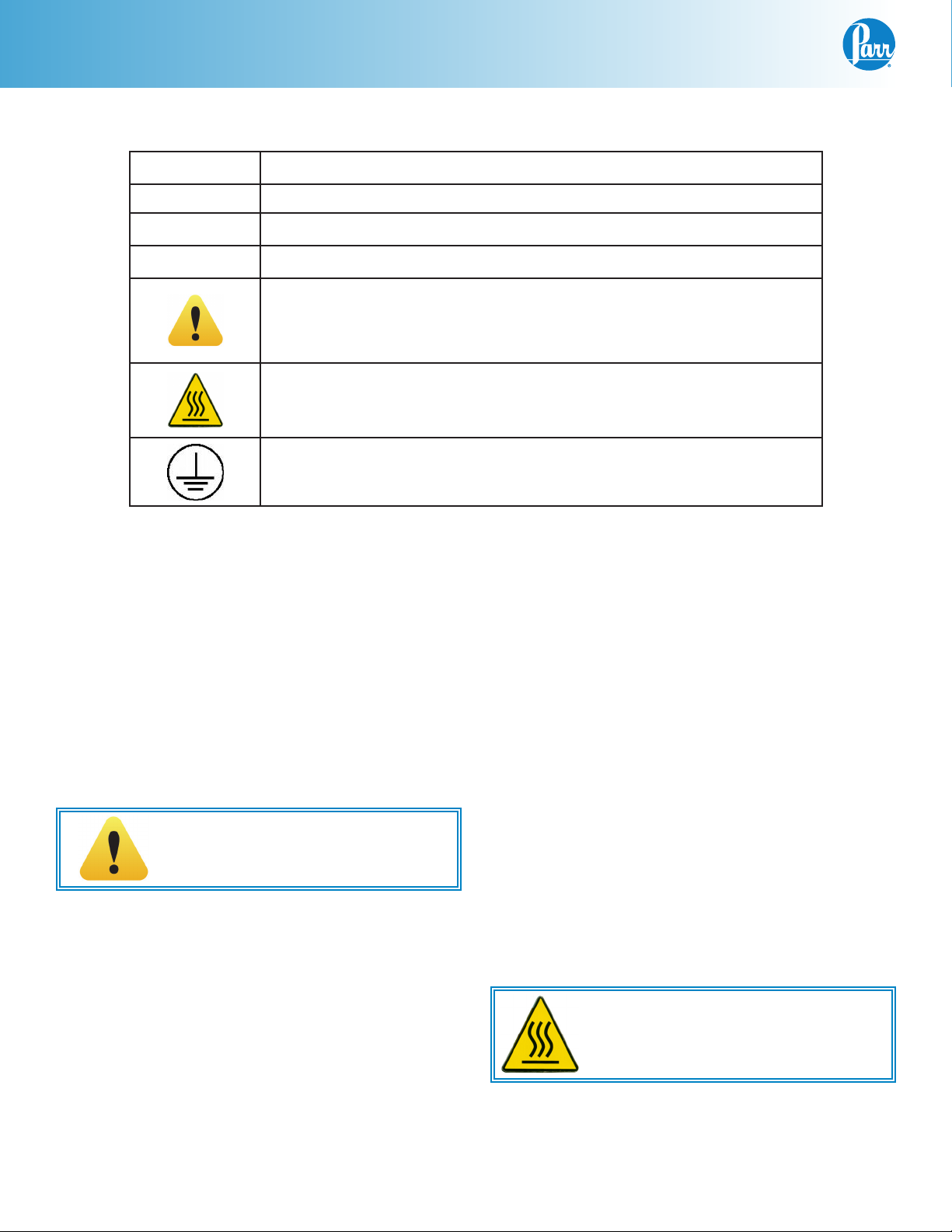
Explanation of Symbols
II On position, full power heater switch
I On position, half power heater switch
O Off Position
~ Alternating Current (AC)
This CAUTION symbol may be present on the Product Instrumentation
and literature. If present on the product, the user must consult the appropriate part of the accompanying product literature for more information.
This CAUTION symbol indicates that the surface may be hot.
Protective Earth (PE) terminal. Provided for connection of the Protective Earth (green or green/yellow) supply system conductor.
Environmental Conditions
This instrument is intended to be used indoors.
Operating: 15 °C to 35 °C; maximum relative humidity of 80% non-condensing. Installation Category II
(overvoltage) in accordance with IEC 664. Pollution
degree 2 in accordance with IEC 664.
Altitude Limit: 0 to 2000 meters above sea level.
Storage: -25°C and 65°C; 10% to 85% relative humidity.
Caution!
Do not use in hazardous atmospheres.
Intended Usage
This system has been designed for use as a high
pressure reactor system. It has been designed, built,
and tested to strict physical and electrical standards.
However, it is the user’s responsibility to install and
operate it in conformance with local pressure and
electrical codes.
If this equipment is used in a manner beyond its intended usage, the protection provided by the equipment may be impaired.
Provisions for Lifting and Carrying
The reactor and its components are very heavy. Before moving ensure all cables are disconnected. Use
proper and safe lifting techniques when installing or
moving the reactor and/ or its components.
Cleaning & Maintenance
Periodic cleaning may be performed on the exterior
surfaces of the instrument with a lightly dampened
cloth containing mild soap solution. All power should
be disconnected when cleaning the instrument.
There are no user serviceable parts inside the product other than what is specifically called out and
discussed in this manual. Advanced troubleshooting
instructions beyond the scope of this manual can be
obtained by calling Parr Instrument Company in order
to determine which part(s) may be replaced or serviced.
Ensure that any hot surfaces have had
adequate time to cool before cleaning
or maintaining the reactor and/or its
components.
4
Parr Instrument Company
Page 5

Compact Micro Reactors
User’s Responsibility
All Parr Reactors and Pressure Vessels are designed
and manufactured with great care to assure safe
operation when used within their prescribed temperature and pressure limits. But…the basic responsibility for safety when using this equipment
rests entirely with the user; who must:
1. Select a reactor or pressure vessel that has the
capability, pressure rating, corrosion resistance,
and design features that are suitable for its
intended use. Parr engineers will be glad to discuss available equipment and material options
with prospective users, but the final responsibility for selecting a reactor or pressure vessel
that will perform to the user's satisfaction in any
particular reaction or test must rest with the user
- not with Parr.
In exercising the responsibility for the selection
of pressure equipment, the prospective user
is often faced with the choice between over-or
under-designed equipment. The hazards introduced by under-designed pressure vessels are
readily apparent, but the penalties that must be
paid for over-designed apparatus are often overlooked. Recognizing these criteria, Parr reactors and pressure vessels are offered in several
different styles, each designed for convenient
use in daily operation within certain temperature
and pressure limits, using gaskets, closures and
other elements carefully selected for safe operation within the limits specified for that design.
But in order to preserve the validity of these designs, all temperature and pressure limits must
be observed, and no attempt should be made to
increase these limits by making alterations or by
substituting components which are not recommended by Parr Instrument Company.
2. Install and operate the equipment within a
suitable barricade, if required, with appropriate
safety accessories and in full compliance with
local safety codes and rules.
All standard Parr pressure vessels are provided
with either a suitable relief device or a means
to attach one (typically in the form of a plugged
opening). When a pressure vessel is delivered
without a pressure venting device, it is the customer’s responsibility to provide pressure relief
in order to protect the operator and the equipment from destructive high pressures. If you
need more information or need help in selecting
a proper relief device, please contact Parr Instru-
ment Company.
3. Establish training procedures to ensure that any
person handling the equipment knows how to
use it properly.
4. Maintain the equipment in good condition and
establish procedures for periodic testing to be
sure the vessel remains structurally sound.
Unpack Carefully
Unpack the equipment carefully and check all the
parts against the packing list. If shipping damage is
discovered, report it immediately to the delivering
carriers. The vessel, motor, heater, and controller
may be packed separately for convenience in shipping, but these parts are easily reassembled. Examine the components closely for any loose parts or
shipping damage and be sure to check all layers of
packing materials thoroughly so as not to overlook
any parts which might otherwise be discarded.
www.parrinst.com
5
Page 6
Compact Micro Reactors
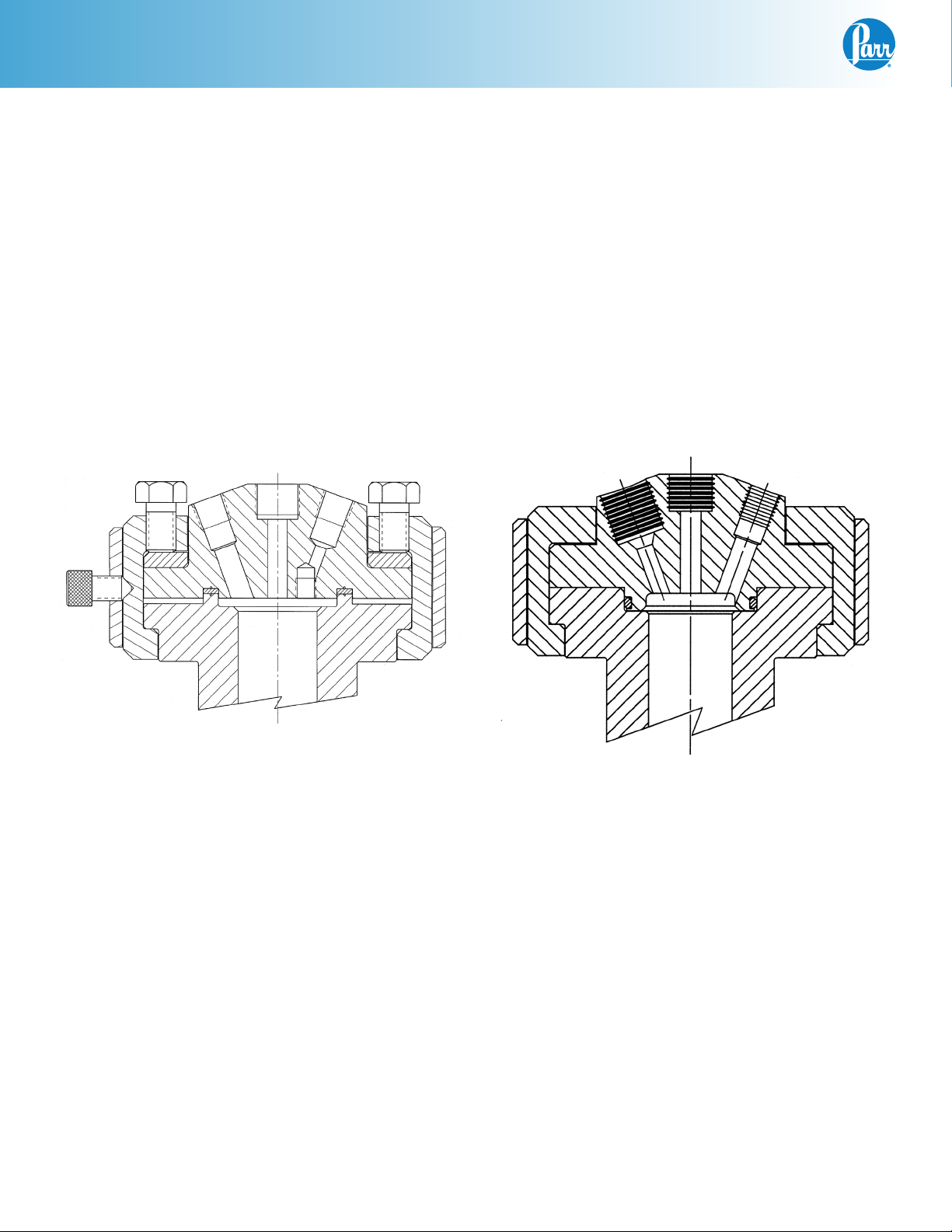
Flat PTFE Gasket or Self Sealing O-Ring Closure
The flat gasket is held in a recess in the vessel head
and a machine pilot on the cylinder closes the recess to completely contain the gasket. The split ring
closure used with this gasket has six cap screws
which must be tightened to develop the loading on
the gasket.
The self sealing design features an O-ring retained
in a groove on the vessel head. This design is self
sealing and the split ring used with this sealing system does not require nor have the cap screws used
with the flat gasket.
The face seal O-ring with screw cap closure is designed to be simply hand tightened.
The flat PTFE gasket can be used to operating temperatures as high as 350 ºC. The maximum temperature of the vessels equipped with O-ring seals
depends upon the material used for the O-ring. The
most common material is a fluoroelastomer (FKM)
which has a 225 ºC maximum operating temperature limit.
Moveable Head with PTFE Gasket Moveable Head with O-ring Seal & Easy Close Split Ring
6
Parr Instrument Company
Page 7

Compact Micro Reactors
Installation
Pressure and Temperature Limits
Working pressures up to 3000 psig (200 bar)
maximum are permissible in these micro reactors
when constructed of Type 316 Stainless Steel and
equipped with a magnetic stirrer drive. Pressure
limits for reactors made of materials other than
Type 316 Stainless Steel can be obtained from Parr
Customer Service. No attempt should be made to
increase these limits by making alterations or by
substituting components which are not recommended by Parr Instrument Company. It must also
be understood that lower pressure and temperature
limits may be required for modified reactors and for
vessels made of special. Limits for such vessels will
be determined by the physical characteristics of the
material of construction and will be prescribed on
an individual basis.
Working temperatures up to 350 ºC are permissible
in micro reactors equipped with a standard, flat
gasket, No. 429HC2, made of PTFE fluoropolymer
resin. A PTFE gasket is the recommended choice
for most applications since the PTFE resin is inert to
most chemicals and it will provide good seals under
repeated opening and closing if the gasket temperature does not exceed 350 ºC. The service life of a
PTFE gasket will, however, be reduced considerably
if used at temperatures above 300 ºC. For better service in the 300 ºC to 350 ºC operating range Parr recommends a flexible graphite gasket, No. 429HC2KL.
The maximum working pressure and temperature
for any vessel is governed by the design of the
vessel and the strength of the material from which
it is constructed. There is also a close relationship
between working pressure and temperature since
the strength of any material will normally fall off
as the temperature is increased. Temperature and
pressure limits are also affected by the physical
properties and temperature limits of the gaskets and
seals used in the vessel, and by any valves, gages
or other fittings attached to the vessel. Obviously,
the safe operating pressure of any system can be no
higher than that of its lowest rated component.
Working temperatures up to 225 ºC are permissible
in micro reactors equipped with fluoroelastomer
(FKM) O-ring seals. The higher the operating temperature above 200 ºC, the shorter the life of the Oring will be. Perfluoroelastomer (FFKM) O-ring seals
have a broad chemical resistance and can be used
to temperatures up to 300 ºC. Unfortunately they
are very expensive and will generally be reserved
for unique applications. Ethylene-propylene (EP)
O-rings can be used to 170 ºC and are recommended for applications such as ethers, ammonia and
amines which will rapidly destroy fluoroelastomer
O-rings.
The working pressure and temperature in these 25,
50 & 100 mL reactors must not exceed the following
maximum limits:
Pressure and Temperature Limits
Bomb
Material
T316SS 3000 psig 350 ºC PTFE Flat Gasket
T316SS 3000 psig 225 ºC FKM O-Ring
T316SS 3000 psig 300 ºC FFKM O-Ring
Maximum
Pressure
Maximum
Temperature
www.parrinst.com
7
Page 8

Compact Micro Reactors
Assemble The Reactor
These reactors require at least 3 sq. ft. of work space
on a sturdy bench or table in a well ventilated area
with convenient access to an electric outlet, running
water, and a drain. If the tabletop is not heat resistant
it would be ideal to provide an insulated pad on which
to set the vessel when it is hot.
1. Set the Reactor Controller near the reactor, leaving a space of at least six inches between the
controller and the base of the reactor so that the
controller will not be unduly affected by radiant
heat. Connect the reactor to the controller using
information contained in its Instruction Manual
548M or follow the steps below.
Labeled connections are provided on the rear panel
of the controller.
Parr Cooling Only:
3. Plug the motor cord into the motor socket on the
rear of the controller.
Secure the clamp on the motor cord
with the provided screw next to the
motor socket for safety purposes.
4. Connect the thermocouple and extension wire
to both the thermocouple and to the controller
in the “Primary Temp Input” position on the rear
panel. Insert the thermocouple in the thermowell.
5. Connect leads from accessory packages such as
tachometer, pressure transducer and high temp
cut-off to the designated positions on the back
panel of the 4848 Reactor Controller.
6. Connect cooling water to the magnetic drive.
See Instruction Manual No. 441M.
7. Connect tubing to the rupture disc outlet and run
to a safely vented area. See Instruction Manual
231M.
The Parr Cooling output connector is to be used only
with Parr Instrument Company cooling solenoid valve
assemblies supplied with the appropriate cooling
power cord.
Parr Heating Only:
The Parr Heating output connector is to be used only
with Parr Instrument Company heater assemblies
supplied with the appropriate heater power cord.
Note: Do not make connections to a Variac,
Powerstat or the like to attempt to control the
heating output. The heavy inductive load on
the primary side of such devices can destroy
the internal sold state relay located in the 4848
Reactor Controller.
The Motor output connector is to be used only with
Parr Instrument Company motor assemblies supplied with the appropriate motor power cord.
2. Connect the heater cord from the heater into
the heater socket on the rear panel of the Series
4848 Reactor Controller.
8. Connect the motor to the stirrer by lifting the motor/overrarm approximately 1/2 inch and rotating
it into position above the reactor‘s center. Then
slowly move the motor/overrarm downward until
the two halves of the coupling connect. Up to 45
degrees manual rotation of the coupling halves
relative to each other may be necessary in order
in order to mesh them properly.
9. Note the voltage and amperage requirement
stamped on the controller data plate, and then
plug the power cord into an appropriate outlet.
Power for these reactors should be drawn from
a grounded outlet capable of carrying up to the
full current rating of the reactor.
10. If an electric stirrer motor is supplied, turn the
speed control knob fully counterclockwise on
the Reactor Controller, turn on the motor switch
and slightly increase the speed for a short run
to check the stirrer drive system but do not turn
on the heater, put heater toggle switch in center
position (OFF). There must always be a vessel in
the heater when it is turned on, and the vessel
and heater sizes must match. If the heater is operated without proper size vessel in contact with
the mantle, the mantle may overheat and fail.
8
Parr Instrument Company
Page 9

Compact Micro Reactors
Identify The Valves
Gas Inlet Valve
The gas inlet valve is easily identified when the
vessel is open by noting that it is connected to a dip
tube which extends to a point near the bottom of
the cylinder. With this arrangement, incoming gas is
always introduced below the surface of the liquid.
This valve includes a coupling with an “A” socket
connection for attachment of the pressure hose.
Gas Release Valve
The gas release valve is typically connected to a side
opening on the gage adapter. Gas released from
this valve will be drawn from the top of the reactor.
Liquid Sampling Valve
The liquid sampling valve is attached to the same
fitting as the gas inlet valve and connected to the
same dip tube. This provides the operator with a
means for clearing the dip tube to be sure that any
sample taken during a run will be representative of
the charge. This can be done by opening the gas
valve momentarily to force any liquid in the dip tube
back into the reactor before withdrawing a sample
from the sampling valve.
OPTIONAL
PRESSURE
TRANSDUCER
GAS INLET
VALVE
LIQUID
SAMPLING
VALVE
NOTE:
SAFETY RUPTURE DISC NOT
SHOWN IN THIS VIEW(LOCATED
BEHIND MAGNETIC DRIVE)
FOR PART NUMBERS AND
ADDITIONAL VIEWS SEE PG. 14
PRESSURE GAGE
MAGNETIC
DRIVE
THERMOCOUPLE
GAS RELEASE
VALVE
Other Vessel Head Fittings
Safety Rupture Disc
There is a safety rupture disc attached to the head
which is intended to rupture and release the pressure
before it reaches a dangerous level. A metal tag wired
to the safety head identifies the burst pressure at room
temperature for that particular disc. A similar tag is
furnished with each replacement disc. This tag must
remain with the apparatus at all times so that both
present and future operators will be aware of the disc
rating. Users should read the discussion of rupture
discs given in the Operating Instruction No. 231M for
a complete description of the characteristics of rupture
discs and the precautions to be observed when operating pressure equipment protected by this type of
safety device.
A typical pre-bulged disc can be used to 90% of the
rating on the tag. For additional protection, the user
should install an adequate and safe venting system
for removing any toxic, flammable or volatile material which would be released if the rupture disc should
burst. A connector for attaching 3/8” OD tubing to the
discharge port of the rupture disc is provided for this
purpose.
Type J Thermocouple
A Type J Thermocouple in a 1/8” diameter Stainless
steel sheath is installed in each reactor. In reactors
made of alloys other than stainless steel, the stainless
thermocouple is installed in a thermowell made of the
same alloy as the vessel. Connect the thermocouple
to the socket on the rear panel of the reactor controller
using the extension wire furnished with the reactor.
Pressure Gage
The pressure gage furnished with this reactor has a
T316 Stainless Steel Bourdon tube. Gages are furnished in a variety of ranges to meet individual needs.
Typically, the gage and the rupture disc are furnished
as matched ranges. For applications where a gage is
selected with a range under 1000 psi, a relief valve is
added and set to protect the gage. A 1000 psi rupture
disc is installed as the fail-safe vessel protection.
For highly corrosive applications where the vapor
phase might corrode the stainless Bourdon tube, Parr
offers isolator assemblies in a variety of materials.
These isolators with their internal piston isolate the
vapors from the gage.
Head Fittings for Micro Reactor
www.parrinst.com
9
Page 10

Compact Micro Reactors
How To Use The Vessel
Removable Head Vessel Flat Gasket Closure
Always remove the vessel from the heater before attempting to open or close them.
To Open the Vessel
Open the gas release valve to discharge any internal
pressure. For the bolted closure loosen the six cap
screws in the split ring sections. Loosen the cone
pointed screw in the outer band and lower the band to
rest on the table. The ring sections can now be removed, and the head with all attached fittings is free to
be lifted from the cylinder. Handle the head carefully
so as not to damage the stirring shaft and other internals when they are outside of the cylinder.
Before Closing the Vessel
Examine the head gasket or O-ring carefully to be
sure that it is in good condition. After considerable
use some of the PTFE gasket may extrude into a thin,
ragged edge around the inside and outside diameters.
This does not necessarily mean that the gasket must
be replaced, but the extruded portion should be removed with a sharp knife. Examine the mating surfaces on the cylinder and head to be sure they are clean
and free from burrs; then set the head on the cylinder.
O-Ring Closures
The split rings used with an O-ring seal do not include
any compression bolts.
With the easy close split ring the O-ring is attached to
the pilot on the underside of the head. When closing the vessel, set the head on the cylinder and press
down on the head until the bottom of the head meets
with the cylinder flange. Then install the two split ring
halves and attach the outer drop band.
Gas Connections
For a gas connection to the vessel, use the A495HC
pressure hose furnished with the reactor. Attach the
hose to a pressure regulator or flow control valve on
a commercial gas cylinder using PTFE tape or other
thread sealant on the 1/8” NPT male nipple and on
the 1/4” NPT bushing, if used. Then screw the Type A
coned pressure fitting into the adapter attached to the
gas inlet valve and tighten the compression nut firmly.
Do not use any thread dope or tape on the coned fitting. The A495HC pressure hose is made of reinforced
Nylon which can be used for all non-corrosive gases
at pressures up to 2500 psig. For operations involving
corrosive gases, this hose should be replaced with an
A490HC hose (optional) which has a PTFE lining and
a braided stainless steel outer covering. These hoses
have the same fittings as in the A495HC.
To Close the Vessel
Slide the two ring sections into place and position
them so that the shallow socket drilled in the outer
surface of one of the ring sections is 180º from the
gage face. Raise the outer band into place around the
ring sections and position the band so that the cone
pointed screw enters the socket described above; then
tighten the screw lightly to hold the band in place.
Sealing Vessels with PTFE Gaskets
Tighten each of the cap screws with the wrench furnished with the apparatus. Apply a firm but hard pull
to each screw. If a torque wrench is available, apply 15
ft-lbs to each screw. DO NOT apply more than 25 ft-lbs
of torque to these bolts as this can deform the head of
the reactor. Tightening should proceed in a criss-cross
pattern rather than progressively around the circle. Let
the vessel stand for about five minutes after the initial
tightening; then tighten the cap screws again. This will
compensate for any tendency of the PTFE gasket to
flow under the loading pressure.
Routinely inspect cap screws on the split ring closure
for lubrication and cleanliness. It is important to clean
and lubricate them periodically so that the required
torque is achieved when tightening the bolts.
Pressurizing the Vessel
Check all valves carefully before admitting gas into the
system. The liquid sampling valve must remain closed
throughout the charging procedure. The gas release
valve must also be closed unless the vessel is to be
purged, or unless there is to be a continuous flow
through the reactor during a run. Always make certain
that the pressure in the gas tank is greater than the
pressure in the vessel; otherwise liquid will be forced
out of the vessel and into the gas tank when the inlet
valve is opened. If there is any possibility that the tank
pressure might not be high enough to force gas into
the reactor, install a one way check valve (optional) in
the gas line to prevent any reverse flow.
With the inlet valve open and the flow control valve on
the gas tank closed, open the main valve on the gas
tank only about one-quarter turn; then use the flow
control valve or the valve on a pressure regulator to
control the flow of gas into the vessel. After the desired pressure has been reached, close the tank valves
and the vessel inlet valve and disconnect the hose at
the vessel end.
10
Parr Instrument Company
Page 11

Compact Micro Reactors
Do Not Overfill the Vessel
Always watch the pressure gage closely when admitting gas so as not to exceed the maximum working
limit. Remember that any subsequent increase in temperature will raise the pressure. Also, be sure that the
amount of liquid placed in the vessel is carefully controlled. As a general rule, the liquid charge should not
exceed two-thirds of the capacity of the cylinder. Too
much liquid in the vessel can lead to development of
dangerous pressures if sufficient space is not provided
for expansion when the liquid is heated. This hazard
is explained in greater detail in a warning statement
included in the Instruction Manual No. 230M.
Releasing Pressure
Use the gas release valve to reduce the pressure in the
vessel if the reactor is accidentally overcharged when
filling. Use this valve also to release any excess pressure during a run and to exhaust the vessel at the end
of a run. If the discharge gases are flammable or toxic,
discharge to an exhaust hood or to any other safe
release point.
Withdrawing Liquid Samples
Liquid samples may be withdrawn from the sampling
valve attached to the same adapter as the gas inlet
valve whenever the vessel is pressurized. Always
close the inlet valve before withdrawing a liquid sample and open the sampling valve cautiously because
liquid will be discharged with considerable force. Be
particularly careful if the temperature of the sample is
above its boiling point at atmospheric pressure. If so,
it will “flash” and be lost as soon as it is released from
the vessel. This problem can be avoided by connecting an optional 4351 Sample Collection Vessel to the
sampling valve to collect the liquid into an appropriate
receiver. The addition of a small amount of gas can be
used to clear the dip tube between liquid samples so
that the next sample drawn through the tube will truly
be representative of the mixture.
Accessories
Liners
Glass or PTFE liners can be furnished to fit most
Parr reactors. These liners slide into the cylinder.
Although they will not keep corrosive vapors from
reaching the surfaces of the cylinder and head, they
make it much easier to add and remove liquid reactants, and they give some protection to the cylinder
when working with corrosive solutions. It must be
noted, however, that adding a PTFE liner will slow
the heat transfer rate into the vessel, and it may be
necessary to adjust the temperature control method
to prevent overheating.
Liner Part Numbers
Fits ID
1.3” 50 mL 1431HC 1431HCHA
1.3” 100 mL 1431HC2 1431HC2HA
Spare Parts Kit
Spare parts kits are available for these reactors. The
kits will provide a reserve supply of parts and tools
sufficient to handle most normal replacements and
emergency repairs during a year of heavy usage.
The kits contain small perishable items required for
continuous operation including gaskets, bushings,
rupture discs and seals. They can be ordered from
any Parr Dealer or direct from the Parr Instrument
Company. The order must specify the reactor size
and indicate type of rupture disc, stirrer drive and
whether it has a flat-gasket or O-ring closure. It is
most advantageous to provide the complete vessel
number from the head or cylinder.
Cylinder
Size
Glass Liner PTFE Liner
Initial Operating Test
Read all operating instructions carefully so as to be
well acquainted with the correct procedures for handling the vessel and for operating the controller and
other accessories. An initial operating test should be
made, with only water, to check the apparatus before
starting the first experimental runs. For this initial test,
fill the cylinder not more than half full of water and run
the temperature up to 150ºC while checking the apparatus for leaks and observing the performance of the
reactor controller.
www.parrinst.com
11
Page 12

Compact Micro Reactors
Periodic Pressure Tests
Each cylinder used in a Parr stirred reactor is tested
under hydrostatic pressure to 1.3 times its maximum rating before it is released from the factory.
Micrometer caliper measurements are taken during
this test to check the deflection of the walls under
pressure. Excessive deflection or failure of the
metal to resume its original dimensions after pressure is released indicates that a cylinder is potentially unsafe and it will be rejected. Similar tests
should be made at regular intervals during the life
of each cylinder, and particularly whenever the user
suspects that the equipment has been over-stressed
or damaged.
Some laboratories maintain hydraulic test facilities
and make it a rule that all pressure vessels must
be tested at regular intervals. Records are kept of
deflections at specific test pressures so that any
increase in deflection becomes a warning that the
metal has lost strength. Any cylinder that fails to
return to its original dimensions after application of
the prescribed hydrostatic test should be discarded
as unsafe for further use.
Users who do not have pressure test facilities can
return any Parr pressure vessel to the factory for hydrostatic testing and overhaul. This should be done
whenever the metal shows excessive damage from
corrosion or whenever an over-pressure or other
unusual occurrence raises any safety questions. To
return a vessel for repair contact Parr Instrument
Company for a return authorization number. Ap-
paratus returned for testing and overhaul should be
shipped prepaid to the Parr Instrument Company,
211-53rd Street, Moline, Illinois 61265. An order or
letter of instructions should be mailed to the same
address, as no repair work will be started without
specific instructions and a Health & Safety Assurance Certification form (F0042) signed by a responsible user.
General Maintenance Notes
1. Periodically inspect all electrical wiring and pressure connections for excessive corrosion. Suspect parts should be replaced by components
only supplied by Parr Instrument Company.
2. Always use appropriate wrenches on all fittings
and valves. Never use pliers or pipe wrenches.
3. Head and cylinder service fixtures are available
for convenience and protection of components
during maintenance of your reactor.
4. NPT (National Pipe Taper) threads should not
be disassembled any more than necessary. It
will become increasingly difficult to maintain a
tight seal with these tapered threads if the joint
is made and broken repeatedly. Grafoil tape or
PTFE tape (if temp allows) should be used on all
NPT threads.
5. Do not use oil or anti-seize lubricant on threads
or fittings if the vessel is to be used with oxygen.
6. If your vessel is equipped with a loose compression ring be sure that it is in place on the head
before attaching any head fittings. The compression ring cannot be installed after fittings have
been screwed into the head.
7. Clean all threads and gas passages thoroughly
and remove all tape fragments when overhauling a vessel.
An ultrasonic bath is excellent for cleaning metal
parts, but do not place a thermocouple probe,
pressure gage, face seals or ball bearings in an
ultrasonic bath. Periodic cleaning may be performed on the exterior surfaces of the reactor
stand with a lightly dampened cloth containing
mild soap solution. All electrical power should
be disconnected when cleaning.
Customer Service
Please contact the Parr Customer Service
Department for an RMA#:
1-309-762-7716 • 1-800-872-7720
Fax: 1-309-762-9453
E-mail: sales@parrinst.com
12
Parr Instrument Company
8. Routinely inspect cap screws on split ring closure for lubrication and cleanliness. These
screws should not be allowed to dry because
the threads will seize. Regularly apply Parr
High Temperature Anti-Seize Lubricant (Parr No.
424HC2) before this happens.
9. If servicing assistance is needed, contact Parr
Instrument Company directly at the address
shown on the back of these instructions.
Page 13

Compact Micro Reactors
Parts Lists
Consult the itemized list for your reactor provided
along with this manual. For purpose of reactor identification the following abbreviation/codes are used:
OR – O-ring FG – Flat Gasket
SC – Screw Cap SR – Split Ring
Cylinders*
Part No. Description Code
1430HC Cylinder, 25 mL SC OR
1430HC2 Cylinder, 50 mL SC OR
1430HC3 Cylinder, 100 mL SC OR
2430HC Cylinder, 25 mL SR FG
2430HC2 Cylinder, 50 mL SR FG
2430HC3 Cylinder, 100 mL SR FG
2900HC Cylinder, 25 mL SR OR
2900HC2 Cylinder, 50 mL SR OR
2900HC3 Cylinder, 100 mL SR OR
Heads*
Part No. Description Code
1432HC Head SC OR
1432HC2 Head SC OR
2432HC Head SR FG
2902HC Head SR OR
Internal Fittings*
Thermowell*
Part No. Description
1467HC Thermowell, 25/50 mL
1467HC2 Thermowell, 100 mL
Dip Tube*
Part No. Description
1443HC Dip Tube, 25 mL
1443HC2 Dip Tube, 50 mL
1443HC3 Dip Tube, 100 mL
Gaskets & Seals
Part No. Description Code
48HC Gasket, silver, mag drive
48HCFG Gasket, gold plated, mag drive
1433HCJK Head Seal, O-ring, FFKM SC OR
1433HCJV Head Seal, O-ring, FKM SC OR
2901HCJK Head Seal, O-ring, FFKM SR OR
2901HCJV Head Seal, O-ring, FKM SR OR
429HC2 Flat Head Gasket, PTFE SR FG
429HC2KL Flat Head Gasket, Flexible Graphite SR FG
* For parts made from alternate materials use the
codes shown below as a suffix to the standard part
number.
CM - Alloy 400 CC - Alloy 20Cb3
CT - Alloy 600 CA - Titanium G2 or G4
CG - Alloy B-2 CX - Zirconium
CH - Alloy C-276
Shaft / Impeller Assembly*
Part No. Description Code
A1987HC Shaft/Impeller, 25/50 mL OR
A1987HC2 Shaft/Impeller, 100 mL OR
A1987HC3 Shaft/Impeller, 25/50 mL FG
A1987HC4 Shaft/Impeller, 100 mL FG
External Fittings*
Part No. Description
A122VB Straight Valve 1/8 NPTM
A146VB Angle Valve 1/8 NPTM
420HC Adapter “A” Socket x 1/8 NPTF
195VBAD Tee, Branch 1/8 NPT MFF
836HC Gage Adapter
A833HC Male Connector for Thermocouple 1/8 T
A138CA* Male Connector for Thermowell ¼ T
A472E Thermocouple, SS, 7-1/2” L
A472E4 Thermocouple, SS, 5-1/2” L
A490E Thermocouple, SS, dual 7-1/2” L
A888HC2 Safety Rupture Disc Assembly (See 231M)
Split Rings and Accessories
Part No. Description Code
1379HC Screw Cap OR
2195HC Split Ring OR
A455HC Split Ring, with six bolts FG
A456HC Drop Band SR
454HC Compression Ring FG
232HCFDE Compression Bolt SR FG
456HCF2 Drop Band Bolt FG OR
Gages
Part No. Description
593HCP1AD Gage, 3-1/2” 100 psi/bar
593HCP2AD Gage, 3-1/2” 200 psi/bar
593HCP6AD Gage, 3-1/2” 600 psi/bar
593HCPD Gage, 3-1/2” 1000 psi/bar
593HCPF Gage, 3-1/2” 2000 psi/bar
593HCPG Gage, 3-1/2” 3000 psi/bar
www.parrinst.com
13
Page 14

Compact Micro Reactors
Micro Head External Fittings
14
Parr Instrument Company
Page 15

Compact Micro Reactors
Vessel Heaters Parts List
The 25, 50 and 100 mL Micro Reactors are equipped with aluminum block heaters. These heaters are made
in two sizes, designed to provide uniform heat distribution to the walls and bottoms of these vessels.
Heater Assemblies
Part No. Description
A3060HCEB
A3060HCEE
A3060HC2EB
A3060HC2EE
A3060HC4EB Heater Assembly, 100mL, 1000W,
A3060HC4EE Heater Assembly, 100mL, 1000W,
Heater Assembly, 25/50mL, 700W, 115V
Heater Assembly, 25/50mL, 700W, 230V
Heater Assembly, 100mL, 1000W, 115V
Heater Assembly, 100mL, 1000W, 230V
115V with cooling
230V with cooling
Part No. Description
1666E4EB Heating Element, 25/50mL, 350W, 115V
1666E4EE Heating Element, 25/50mL, 350W, 230V
1666E5EB Heating Element, 100mL, 500W, 115V
1666E5EE Heating Element, 100mL, 500W, 230V
Replacement Heating Elements
www.parrinst.com
15
Page 16

Compact Micro Reactors
Drawings
Motor/Overarm Layout
16
Parr Instrument Company
Page 17

3089HC Enclosure
(A1523E Filter inside)
1729E Ferrite Core
3048HC2
Enclosure
Tach Option Layout
Compact Micro Reactors
Parts included when apparatus is EMC compliant:
www.parrinst.com
17
Page 18

Compact Micro Reactors
25 mL and 50 mL Vessel Assemblies
18
Parr Instrument Company
Page 19

100 mL Vessel Assembly
Compact Micro Reactors
www.parrinst.com
19
Page 20

445M R05 Revision 11/19/13
 Loading...