

Page 1
5400
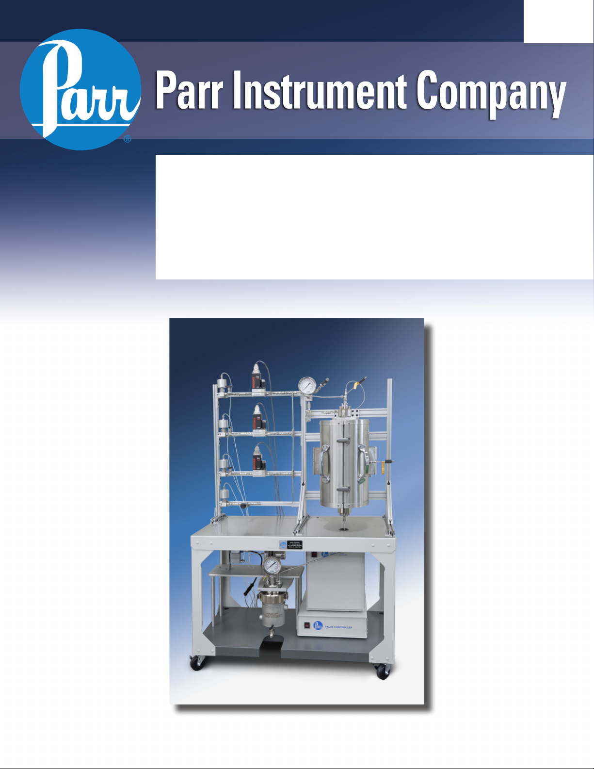
Tubular Reactor Systems
Operating Instruction Manual
624M
Page 2

5400 Tubular Reactor System
Preface 3
Scope 3
Related Instructions 3
Safety Information 3
General Specifications 3
Explanation of Symbols 4
Intended Usage 4
Environmental Conditions 4
Provisions for Lifting and Carrying 4
Unpack Carefully 4
General Assembly 4
Cleaning & Maintenance 5
User’s Responsibility 5
Installation 6
Pressure and Temperature Limits 6
Vessel Head Fittings 9
Safety Rupture Disc 9
Type J Thermocouple 9
Pressure Gage 9
Spare Parts Kit 9
General Maintenance Notes 10
Periodic Pressure Tests 10
Drawings and Parts 11
5401 Tubular Reactor Assembly 11
5402 Tubular Reactor Assembly 11
5403 Tubular Reactor Assembly 12
5404 Tubular Reactor Assembly 13
Series 5400 Tubular Reactor System Specifications 6
Typical Components 7
Reactor 7
Gas Feed 7
Liquid Feed 7
Product Handling 8
Controllers 8
Customer Service
Questions concerning the installation or operation
of this instrument can be answered by the Parr
Customer Service Department:
1-309-762-7716 • 1-800-872-7720
Fax: 1-309-762-9453
E-mail: parr@parrinst.com
http://www.parrinst.com
2
Parr Instrument Company
Page 3

5400 Tubular Reactor System
Preface
Scope
These instructions describe the installation, operation and maintenance of Parr Series 5400 Tubular
Reactor System. They cover the basic steps to be
followed installing these reactors and describe
the function of all standard components. They are
intended to be used in conjunction with several
related instruction sheets listed in the following section. This information describes several components
which are common to most Parr pressure reaction
equipment and includes safety precautions and
other related information applicable to all reaction
laboratories. The users should study all of these
instructions carefully before starting to use these
vessels so that they will fully understand the capabilities and limitations of the equipment.
Related Instructions
The following Parr publications are also included to
further your understanding of this instrument and
its component parts:
Safety Information
To avoid electrical shock, always:
1. Use a properly grounded electrical outlet of
correct voltage and current handling capability.
2. Ensure that the equipment is connected to
electrical service according to local national
electrical codes. Failure to properly connect may
create a fire or shock hazard.
3. For continued protection against possible
hazard, replace fuses with same type and rating
of fuse.
4. Disconnect from the power supply before
maintenance or servicing.
To avoid personal injury:
5. Do not use in the presence of flammable or
combustible materials; fire or explosion may
result. This device contains components which
may ignite such material.
6. Refer servicing to qualified personnel.
No. Description
201M Limited Warranty
230M Safety in the Operation of Laboratory
Reactors and Pressure Vessels
231M
239M 4600 & 4700 General Purpose Pressure
323M Parr Pressure Relief Valves Operating
535M Supplemental Instructions for 4871
548M 4848 Reactor Controller Operating
551M 4838 Temperature Controller Operating
594M A2200E Flow Controller Operating
598M 4877 Valve Controller Operating
668M 1358HC Grafoil® Tape General Guidelines
F0042 Health & Safety Assurance Certification
Safety Rupture Discs Operating Instructions
Vessels Operating Instructions
Instructions
Process Controller
Instructions
Instructions
Instructions
Instructions
General Specifications
Electrical Ratings
Controller ratings are found in the Operating Instructions for the controller supplied with your reactor
and on the controller data plate.
Before connecting a controller to an electrical outlet,
the user must be certain that the electrical outlet has
an earth ground connection and that the line, load
and other characteristics of the installation do not
exceed the following limits:
Voltage: Fluctuations in the line voltage should not
exceed 10% of the rated nominal voltage shown on
the data plate.
Frequency: Controllers can be operated from either
a 50 or 60 Hertz power supply without affecting their
operation or calibration.
Current: The total current drawn should not exceed
the rating shown on the data plate on the controller
by more than 10 percent.
www.parrinst.com
3
Page 4
5400 Tubular Reactor System
Explanation of Symbols
II On position, full power heater switch
I On position, half power heater switch
O Off Position
~ Alternating Current (AC)
This CAUTION symbol may be present on the Product Instrumentation
and literature. If present on the product, the user must consult the appropriate part of the accompanying product literature for more information.
This CAUTION symbol indicates that the surface may be hot.
Protective Earth (PE) terminal. Provided for connection of the Protective Earth (green or green/yellow) supply system conductor.
Intended Usage
This system has been designed for use as a high
pressure reactor system. It has been designed, built,
and tested to strict physical and electrical standards.
However, it is the user’s responsibility to install
and operate it in conformance with local pressure
and electrical codes. If this equipment is used in a
manner beyond its intended usage, the protection
provided by the equipment may be impaired.
Environmental Conditions
This instrument is intended to be used indoors.
Caution!
Do not use in hazardous atmospheres.
Operating: 15 ºC to 35 ºC; maximum relative humidity of 80% non-condensing. Installation Category II
(over voltage) in accordance with IEC 664.
Pollution degree 2 in accordance with IEC 664.
Provisions for Lifting and Carrying
The 5400 Tubular Reactor System and its components are very heavy. Before moving ensure all
cables are disconnected. Use proper and safe lifting
techniques when installing or moving the 5400 Tubular Reactor System and/ or its components.
Unpack Carefully
Unpack the equipment carefully and check all the
parts against the packing list. Ensure that all layers
of the foam packing are inspected and verify that
all components have been removed before packing materials are discarded. If shipping damage is
discovered, report it immediately to the delivering
carriers. The reactor, cart, gas feed system, liquid
feed system, product handling equipment and controllers may be packaged separately for convenience
in shipping, but these parts are easily reassembled.
Examine the components closely for any loose parts
or shipping damage and be sure to check all layers
of packing materials thoroughly so as not to overlook any parts which might otherwise be discarded.
Altitude Limit: 2,000 meters.
Storage: -25 °C and 65 °C; 10% to 85% relative
humidity.
4
Parr Instrument Company
General Assembly
Although all tubular reactor systems are custom
built to the customer’s needs, the general assembly
is typical for each unit. The general assembly consists of mounting the gas feed rack and the reactor/
Page 5
5400 Tubular Reactor System
heater assembly on to the base of the cart using
the provided mounting holes. The gas feed rack is
located on the left side of the cart and the reactor
is on the right. The racks should be mounted to the
cart using the provided bolts and wing nuts. These
nuts should be checked periodically to ensure that
they are tight.
Cleaning & Maintenance
Periodic cleaning may be performed on the exterior
surfaces of the instrument with a lightly dampened
cloth containing mild soap solution. All power should
be disconnected when cleaning the instrument.
User’s Responsibility
All Parr Reactors and pressure vessels are designed
and manufactured with great care to assure safe
operation when used within their prescribed temperature and pressure limits. But . . . the basic
responsibility for safety when using this equipment
rests entirely with the user; who must:
1. Select a reactor or pressure vessel which has the
capability, pressure rating, corrosion resistance
and design features that are suitable for its intended use. Parr engineers will be glad to discuss available equipment and material options
with prospective users, but the final responsibility for selecting a reactor or pressure vessel
that will perform to the user’s satisfaction in any
particular reaction or test must rest with the user
– not with Parr.
In exercising the responsibility for the selection
of pressure equipment, the prospective user is
often faced with a choice between over- or underdesigned equipment. The hazards introduced
by under-designed pressure vessels are readily
apparent, but the penalties that must be paid for
over-designed apparatus are often overlooked.
Recognizing these criteria, Parr reactors and
pressure vessels are offered in several different
styles, each designed for convenient use in daily
operation within certain temperature and pressure limits, using gaskets, closures and other
elements carefully selected for safe operation
There are no user serviceable parts inside the product other than what is specifically called out and
discussed in this manual. Advanced troubleshooting
instructions beyond the scope of this manual can
be obtained by calling Parr Instrument Company in
order to determine which part(s) may be replaced or
serviced.
Ensure that any hot surfaces have had
adequate time to cool before cleaning
or maintaining the reactor and/or its
components.
within the limits specified for that design. But in
order to preserve the validity of these designs,
all temperature and pressure limits must be
observed, and no attempt should be made to
increase these limits by making alterations or by
substituting components which are not recommended by Parr Instrument Company.
2. Install and operate the equipment within a
suitable barricade, if required, with appropriate
safety accessories and in full compliance with
local safety codes and rules.
All standard Parr pressure vessels are provided
with either a suitable relief device or a means
to attach one (typically in the form of a plugged
opening). When a pressure vessel is delivered
without a pressure venting device, it is the customer’s responsibility to provide pressure relief
in order to protect the operator and the equipment from destructive high pressures. If you
need more information or need help in selecting
a proper relief device, please contact Parr Instrument Company.
3. Establish training procedures to ensure that any
person handling the equipment knows how to
use it properly.
4. Maintain the equipment in good condition and
establish procedures for periodic testing to be
sure the vessel remains structurally sound.
www.parrinst.com
5
Page 6

5400 Tubular Reactor System
Installation
Bolt the stand to the floor using the holes
identified on the baseplate.
Pressure and Temperature Limits
The working pressure and temperature at which any
reactor or pressure vessel can be used will depend
upon the design of the vessel and the materials
used in its construction. Since all materials lose
strength at elevated temperatures, any pressure
rating must be stated in terms of the temperature at
which it applies. The standard material of construction for Parr Instrument Company is type 316 Stainless Steel.
Limits for vessels made of other materials and for
other operating temperatures can be obtained from
Parr Customer Service. No attempt should be made
to increase these limits by making alterations or by
substituting components that are not recommended
by Parr Instrument Company. It must also be
understood that lower pressure and temperature
limits may be required for modified reactors and for
vessels made of special alloys.
Limits for vessels will be determined by the physical characteristics of the vessel material and will be
prescribed on an individual basis.
The maximum working pressure and temperature
for any vessel is governed by the design of the
vessel and the strength of the material from which
it is constructed. There is also a close relationship
between working pressure and temperature since
the strength of any material will normally fall off
as the temperature is increased. Temperature and
pressure limits are also affected by the physical
properties and temperature limits of the gaskets and
seals used in the vessel, and by any valves, gages or
other fittings attached to the vessel. The safe operating pressure of any system can be no higher than
that of its lowest rated component. All Parr reactors
show the maximum safe operating pressure and
temperature imprinted on the cylinder.
Series 5400 Tubular Reactor System Specifications (T316 Stainless Steel)
Shaded bar indicates specifications that change within series.
Model Number 5401 5402 5403 5404
Sizes 3/8 in. 1/2 in. 1.0 in. 1.5 in.
O.D. / I.D. (in.) 0.38 / 0.28 0.50 / 0.37 1.9 / 1.0 2.0 / 1.5
O.D. / I.D. (mm) 9.5 / 7.0 13 / 9.4 48 / 25 51 / 38
Heated Length (in.) 6, 12, 24 12, 24, 36
Max. Pressure (psi) 3000 5000 3000
Max. Temperature 550 550 350
Support Spools No Yes
Spiral Pre-Heat No Yes
No. Ports in Top Head 1 4
No. Ports in Bottom Head 1 4
Internal Thermocouple Yes
6
Parr Instrument Company
Page 7

5400 Tubular Reactor System
Typical Components
Reactor
There are two basic styles of tubular reactors available from Parr Instrument Company. The smaller
diameter reactors are available with either a 3/8”
O.D. (model 5401) or a ½” O.D. (model 5402). The
larger diameter reactors are available with either
a 1” I.D. (model 5403) or a 1.5” I.D. (model 5404).
Either style can be easily removed from the assembly for catalyst loading, cleaning or inspection.
To remove the smaller diameter reactors, the pressure should be released either through the BPR or
the manual vent valve. Loosen the compression
fittings on the top and bottom of the reactor. The tubular reactor can now be removed from the system.
Catalyst should be loaded into the bottom of the
reactor with a small amount of glass wool or other
inert material to hold the catalyst in place. Once
the catalyst is installed, the tubular reactor can be
reinstalled and the compression fittings tightened
with wrenches for a pressure tight seal.
The larger diameter reactors utilize a split ring
assembly on the top and bottom as well as a flat
gasket. As with the smaller units, the pressure
should be released either through the BPR or the
manual vent valve. Loosen the compression fittings on both the reactor inlet and outlet. The entire
reactor assembly can now be removed and taken to
a bench for catalyst loading, cleaning and inspection. Loosen the six Compression bolts on the split
ring sections for each end. If equipped, the internal
pre-heat spiral can be inserted into the top of the
reactor. Catalyst should be loaded into the bottom
of the reactor with glass wool to hold it in place.
Catalyst support spools can also be loaded into the
bottom of the reactor if desired.
Examine the head gaskets on both the top and
bottom heads. If flexible graphite gaskets were
used, the old gaskets may need to be removed and
replaced each time the reactor is disassembled.
Typically PTFE gaskets can be used multiple times.
After considerable use, some of the PTFE gasket
may extrude into a thin, ragged edge around the
inside and outside diameters. This does not necessarily mean that the gasket must be replaced, but
the extruded portion should be removed with a
sharp knife.
Once everything has been inspected, the heads can
be reinstalled to the reactor cylinder with the split
ring closures. Tighten each of the cap screws with
the wrench furnished with the apparatus. Tightening should proceed in a criss-cross pattern rather
than progressively around the circle. When the
split ring assembly is completed, the reactor can
be reinserted into the complete assembly and the
compression fittings can be retightened.
Gas Feed
The gas feed system typically consists of at least
one gas mass flow controller (MFC) and a gas purge
line. Either a 4871 controller or an A2200E controller
are required to introduce the set point to the MFC.
The instrument will then compare the actual flow
rate delivered to the set point and automatically
adjust an integral control valve to assure a constant
flow. Each MFC will be marked with the type of gas
to be metered, the maximum operating pressure,
the maximum flow rate and the calibrated pressure settings. The gas source should be connected
with a suitable tubing connector to the inlet of the
gas manifold with care taken as to not exceed the
pressure ratings of the MFC. Each MFC provided
will include the suppliers manual for reference. The
purge line should similarly be connected with a
suitable tubing connector to the purge connection.
The needle valve in the purge line can be used to
manually set the flow of the purge gas through the
system.
If the Tubular Reactor System is controlled by a 4871
Process Controller, the shut-off valves are typically
automated on/off valves. Valves connected to a gas
feed line equipped with any MFC are typically programmed to open when a set point is entered into
the controller and to close when the flow set point
is set to zero or upon loss of power or pressure. The
automated valves require a Parr 4877 Valve Controller to interface with the 4871 Process Controller. A
source of 100 psig of dry air or nitrogen is required
to be connected to the 4877 controller in order
to operate the automated valves. Reference the
supplemental manual for the 4877 Valve Controller
for a more detailed description.
Liquid Feed
High pressure piston pumps are most often used to
inject liquids into a pressurized reactor operating in
a continuous-flow mode. The liquid feed in a Series
www.parrinst.com
7
Page 8

5400 Tubular Reactor System
5400 Tubular Reactor System generally consists of
one or more HPLC pumps rated for up toeither 1500
or 5000 psig. For best results, the pumps should
be located on the bottom shelf of the reactor cart
with the liquid supply source located on the upper
shelf. The inlet to the pump should be connected
using the tubing and filter assembly provided by
the pump manufacturer with the pump. The pump
outlet utilizes 1/16” tubing connected to a check
valve at the top of the tubular reactor. The flow rate
delivered by the HPLC pump can be manually set
on the faceplate of the pump as well as the starting/
stopping of the pump. If a 4871 Process Controller
is being used, these functions can also be performed remotely. For operation and maintenance of
the pumps, see the supplier manual provided with
each pump.
Product Handling
The product handling components of a typical
Series 5400 Tubular Reactor System consist of a
cooling condenser, a gas/liquid separator and a
back pressure regulator (BPR). In order to cool the
product stream from the reactor, a tube-and-shell
heat exchanger is used to act as a cooling condenser. Generally a low flow of water is all that is
required to significantly cool the product. With the
tube side of the condenser connected between the
reactor and the gas/liquid separator, water can be
connected to the hose barbs on the shell side of the
condenser for cooling. The outlet side of the shell
should be routed to a drain for continuous flow of
water through the condenser.
The reactor and separator vessel are kept at a constant pressure through the use of a back pressure
regulator (BPR). This style of regulator will release
products only when the system pressure exceeds a
preset value. The BPR can either be a manual style
regulator with a knob, adjustable by the operator,
to set the desired system pressure or an automated
BPR system controlled by a 4871 Process Controller.
The automatic system consists of a current-to-pressure (I/P) converter and an air loaded BPR. Through
the controller, the system pressure is monitored and
compared to the set point and adjusted by sending an electronic signal to the I/P converter which
adjusts the air pressure to the diaphragm on the air
loaded BPR. A source of 100 psig of dry air or nitrogen is required to be connected to the I/P converter.
For complete details on each of the components,
see the supplied manufacturer manuals.
Because of the inherent nature of the BPRs (both
manual and automated) there may be some systems which the pressure may not vent completely to
atmospheric pressure using the BPR only. A manual
valve is included in the vent line upstream of the
BPR so that the system pressure can be vented
completely when desired.
Controllers
Series 5400 Tubular Reactor Systems are generally
equipped with one of two different types of controller solutions: a “manual” system which utilizes a
number of different controllers to provide the overall control system or the 4871 Process Controller.
The cooled product stream is generally routed to a
gas/liquid separator. In the separator vessel, liquids
are condensed and collected in the bottom of the
vessel. Gases and non-condensed vapors are allowed
to leave the top of the vessel. The gas/liquid separator
is generally sized to act as a liquid product receiver
that can be manually drained periodically. The gas/
liquid separator is generally one of the non-stirred
pressure vessels made by Parr Instrument Company.
More information about our non-stirred
pressure vessels can be found in operating
instruction no. 239M for series 4600 & 4700
General Purpose Vessels.
8
Parr Instrument Company
The manual control system will include a Parr 4848
or 4838 controller for each heater zone. The external
temperature of each zone is monitored and controlled in order to maintain the desired temperature
set point. Additionally, variables such as the system
pressure or internal temperatures can be displayed
on modules dedicated to these functions on the
individual controllers. Similarly, the Parr A2200E
controller is utilized to provide the flow set point to
the MFC as well as display the resulting flow. The
A2200E can be utilized to interface with up to four
MFCs. A manual BPR is used to control the system
pressure. For a detailed description of each of these
controllers, the corresponding manuals should be
referenced.
Page 9

5400 Tubular Reactor System
For many Series 5400 Tubular Reactor Systems, the
advanced controls provided by the 4871 Process
Controller are preferred. The 4871 controller can
monitor the temperature of each heated zone and
control the temperature of each zone independently
or by maintaining the outer temperatures based
on the internal temperatures. The 4871 Process
Controller is connected to either a number of 4875
Power Controllers or a single 4876 Power Controller
in order to provide power to each heated zone. Furthermore, the 4871 can be connected to a 4877 Valve
Controller to open/close up to twelve automated
valves. The control of the gas feeds, liquid feeds,
temperature and pressure can be maintained from
a single source and are configured as each system
requires. The 4871 Process Controller is capable
of performing a number of functions in the event
of any of the configured alarm conditions have
become active. The 4871 Process Controller (along
with the SpecView graphical user interface) is also
capable of logging data and creating custom reports
of any of the logged data points. The 4871 Process
Controller manual as well as the information located
in the custom CD distributed with each 4871 Process Controller should be referenced for additional
information.
Refer to the appropriate controller operating
instructions for specific installation and
maintenance instructions.
characteristics of rupture discs and the precautions
to be observed when operating pressure equipment
protected by this type of safety device.
A typical pre-bulged disc can be used to 90% of the
rating on the tag. For additional protection, the user
should install an adequate and safe venting system
for removing any toxic, flammable or volatile material which would be released if the rupture disc
should burst. A connector for attaching 3/8” OD
tubing to the discharge port of the rupture disc is
provided for this purpose.
Type J Thermocouple
A Type J thermocouple in a stainless steel sheath is
furnished with the reactor. Insert this thermocouple
into the thermowell and connect it to the thermocouple socket on the rear panel of the temperature
controller using the extension wire furnished with
the reactor.
Pressure Gage
The pressure gage furnished with this system has
a T316 Stainless Steel Bourdon tube. Gages are
furnished in a variety of ranges to meet individual
needs. Typically, the gage and the rupture disc are
furnished as matched ranges. For applications
where a gage is selected with a range under 1000
psi, a relief valve is added and set to protect the
gage. A 1000 psi rupture disc is installed as the failsafe vessel protection.
Vessel Head Fittings
Safety Rupture Disc
There is a safety rupture disc attached to the gas
inlet that is intended to rupture and release the pressure before it reaches a dangerous level. A metal tag
wired to the safety head identifies the burst pressure at room temperature for that particular disc.
A similar tag is furnished with each replacement
disc. This tag must remain with the apparatus at all
times so that both present and future operators will
be aware of the disc rating. Users should read the
discussion of rupture discs given in the Instruction
Sheet No. 231M for a complete description of the
Spare Parts Kit
Parr can furnish spare parts kits for these systems
which will provide a reserve supply of parts and
tools sufficient to handle most normal replacements
and emergency repairs during a year of heavy
usage.
These kits contain replacement gaskets, packing, Orings, and rupture discs. They can be ordered from
any Parr Dealer or direct from the Parr Instrument
Company. The order must specify the reactor size
and indicate type of rupture disc. Always provide
the reactor serial number (stamped on head and
cylinder) to assure receipt of proper replacement
parts.
www.parrinst.com
9
Page 10

5400 Tubular Reactor System
General Maintenance Notes
1. Periodically inspect all electrical wiring and pressure connections for excessive corrosion. Suspect parts should be replaced by components
only supplied by Parr Instrument Company.
2. Always use appropriate wrenches on all fittings
and valves. Never use pliers or pipe wrenches.
3. Head and cylinder service fixtures are available
for convenience and protection of components
during maintenance of your reactor.
4. NPT (National Pipe Taper) threads should not
be disassembled any more than necessary. It
will become increasingly difficult to maintain a
tight seal with these tapered threads if the joint
is made and broken repeatedly. Grafoil tape or
PTFE tape (if temp allows) should be used on all
NPT threads.
Note: Do not use Grafoil® tape on the straight
thread connections of the coned adapters and
mating bushings. Grafoil® Tape should only
be used on the (NPT) threads on some needle
valves and reactor fittings. Refer to instruction
manual no. 668M 1358HC Grafoil® Tape General
Guidelines for use.
5. Do not use oil or anti-seize lubricant on threads
or fittings if the vessel is to be used with oxygen.
6. Clean all threads and gas passages thoroughly
and remove all tape fragments when overhauling a vessel. An ultrasonic bath is excellent for
cleaning metal parts, but do not place a thermocouple probe, pressure gage, face seals or ball
bearings in an ultrasonic bath. Periodic cleaning
may be performed on the exterior surfaces of
the reactor stand with a lightly dampened cloth
containing mild soap solution. All power should
be disconnected when cleaning.
Periodic Pressure Tests
Each cylinder used in a Parr reactor system is tested
under hydrostatic pressure to 1.3 times its maximum rating before it is released from the factory.
Micrometer caliper measurements are taken during
this test to check the deflection of the walls under
pressure. Excessive deflection or failure of the
metal to resume its original dimensions after pressure is released indicates that a cylinder is potentially unsafe and it will be rejected. Similar tests
should be made at regular intervals during the life
of each cylinder, and particularly whenever the user
suspects that the equipment has been over-stressed
or damaged.
Some laboratories maintain hydraulic test facilities
and make it a rule that all pressure vessels must
be tested at regular intervals. Records are kept of
deflections at specific test pressures so that any
increase in deflection becomes a warning that the
metal has lost strength. Any cylinder that fails to
return to its original dimensions after application of
the prescribed hydrostatic test should be discarded
as unsafe for further use.
Users who do not have pressure test facilities can
return any Parr pressure vessel to the factory for hydrostatic testing and overhaul. This should be done
whenever the metal shows excessive damage from
corrosion or whenever an over-pressure or other
unusual occurrence raises any safety questions. To
return a vessel for repair, contact Parr Instrument
Company for a return authorization number. Ap-
paratus returned for testing and overhaul should
be shipped prepaid to Parr Instrument Company,
211-53rd Street, Moline, Illinois 61265 USA. An
order or letter of instructions should be mailed to
the same address, as no repair work will be started
without specific instructions and a Health & Safety
Assurance Certification form (F0042) signed by a
responsible user.
7. Routinely inspect cap screws on split ring closure for lubrication and cleanliness. These
screws should not be allowed to dry because
the threads will seize. Regularly apply Parr
High Temperature Anti-Seize Lubricant (Parr No.
424HC2) before this happens.
8. If servicing assistance is needed, contact Parr
Instrument Company directly at the address
shown on the back of these instructions.
10
Parr Instrument Company
Customer Service
Please contact the Parr Customer Service
Department for an RMA#:
Phone: 1-309-762-7716
Toll Free: 1-800-872-7720
Fax: 1-309-762-9453
E-mail: sales@parrinst.com
Page 11

Drawings and Parts
5401 Tubular Reactor Assembly
5400 Tubular Reactor System
288VBAD
MALE CONNECTOR
3/8T X 1/4 NPT
5402 Tubular Reactor Assembly
579VBAD
MALE CONNECTOR
1/2T X 1/4 NPT
542VBAD
REDUCING UNION
3/8T X 1/4T
3616HC / HC2 / HC3 / HC4
TUBE CYLINDER
3/8 OD X .277 ID
19.68 [3616HC]
31.68 [3616HC2]
43.68 [3616HC3]
13.68 [3616HC4]
640VBAD
1REDUCING UNION
1/2T X 1/4T
5401 Cylinder Guide
Cylinder
Part No.
Total
Volume
Heated
Length
Heated
Volume
3616HC 20 mL 12 in 10 mL
3616HC2 35 mL 24 in 20 mL
3616HC3 45 mL 36 in 30 mL
3616HC4 15 mL 6 in 5 mL
3525HC / HC2 / HC3 / HC4
TUBE CYLINDER
1/2 OD X 3/8 ID
19.20 (3525HC)
31.20 (3525HC2)
43.20 (3525HC3)
13.20 (3525HC4)
5402 Cylinder Guide
Cylinder
Part No.
3525HC 40 mL 12 in 20 mL
3525HC2 60 mL 24 in 40 mL
3525HC3 80 mL 36 in 60 mL
3525HC4 25 mL 6 in 10 mL
Total
Volume
www.parrinst.com
Heated
Length
Heated
Volume
11
Page 12

5400 Tubular Reactor System
5403 Tubular Reactor Assembly
Internal View
2X A3511HC
DROP BAND ASS'Y
3510HC / HC2 / HC3
CYLINDER
2X 430HC
COMPRESSION RING
2X A3487HC2
SPLIT RING ASS'Y
EACH WITH 6X
33HDF3 BOLTS
3491HC
HEAD
1/8NPT REF
2X
2.975
18.16 (3510HC)
30.16 (3510HC2)
42.16 (3510HC3)
20.38 (3510HC)
(3510HC2)32.38
44.38 (3510HC3)
24.30 (W/ 3510HC)
36.30 (W/ 3510HC2)
48.30 (W/ 3510HC3)
SECTION A-A
.987
1.50
2X 429HC2
PTFE GASKET
429HC2KF
(GRAPHITE)
5403 Cylinder Guide
Cylinder Part No. Total Volume Heated Length Heated Volume
3510HC 250 mL 12 in 150 mL
3510HC2 400 mL 24 in 300 mL
3510HC3 550 mL 36 in 450 mL
1/4NPT
REF
3489HC
HEAD
12
3491HC Head
Top View
3X 1/16NPT REF
A
A
456HCF2 BOLT REF
(DROP BAND)
Parr Instrument Company
3489HC Head
Bottom View
Page 13

2X A3511HC
2X 430HC
5404 Tubular Reactor Assembly
(DROP BAND)
5400 Tubular Reactor System
Internal View
2X
3491HC
HEAD
1/8NPT REF
2.975
DROP BAND ASSY
2X
18.37 (3540HC
30.37 (3540HC2)
42.37 (3540HC3)
(3540HC)
20.38
32.38 (3540HC2)
44.38 (3540HC3)
24.30 (W/3540HC)
36.30 (W/3540HC2)
48.30 (W/3540HC3)
SECTION A-A
3540HC/HC2/HC3
CYLINDER
1.437
1.875
COMPRESSION RING
2X A3487HC2
SPLIT RING ASS'Y
EACH WITH 6X
33HDF3 BOLTS
2X 429HC2
PTFE GASKET
429HC2KF
(GRAPHITE)
1/4NPT
REF
3489HC
HEAD
5404 Cylinder Guide
Cylinder Part No. Total Volume Heated Length Heated Volume
3540HC 550 mL 12 in 350 mL
3540HC2 850 mL 24 in 700 mL
3540HC3 1150 mL 36 in 1000 mL
3491HC Head
Top View
3X 1/16NPT REF
A
A
3489HC Head
Bottom View
456HCF2 BOLT REF
www.parrinst.com
13
Page 14

Notes
14
Parr Instrument Company
Page 15

Notes
www.parrinst.com
15
Page 16

624M R01 12/09/13
 Loading...