

Page 1
No. 402M
r
Parr Instrument Company
Operating Instruction Manual fo
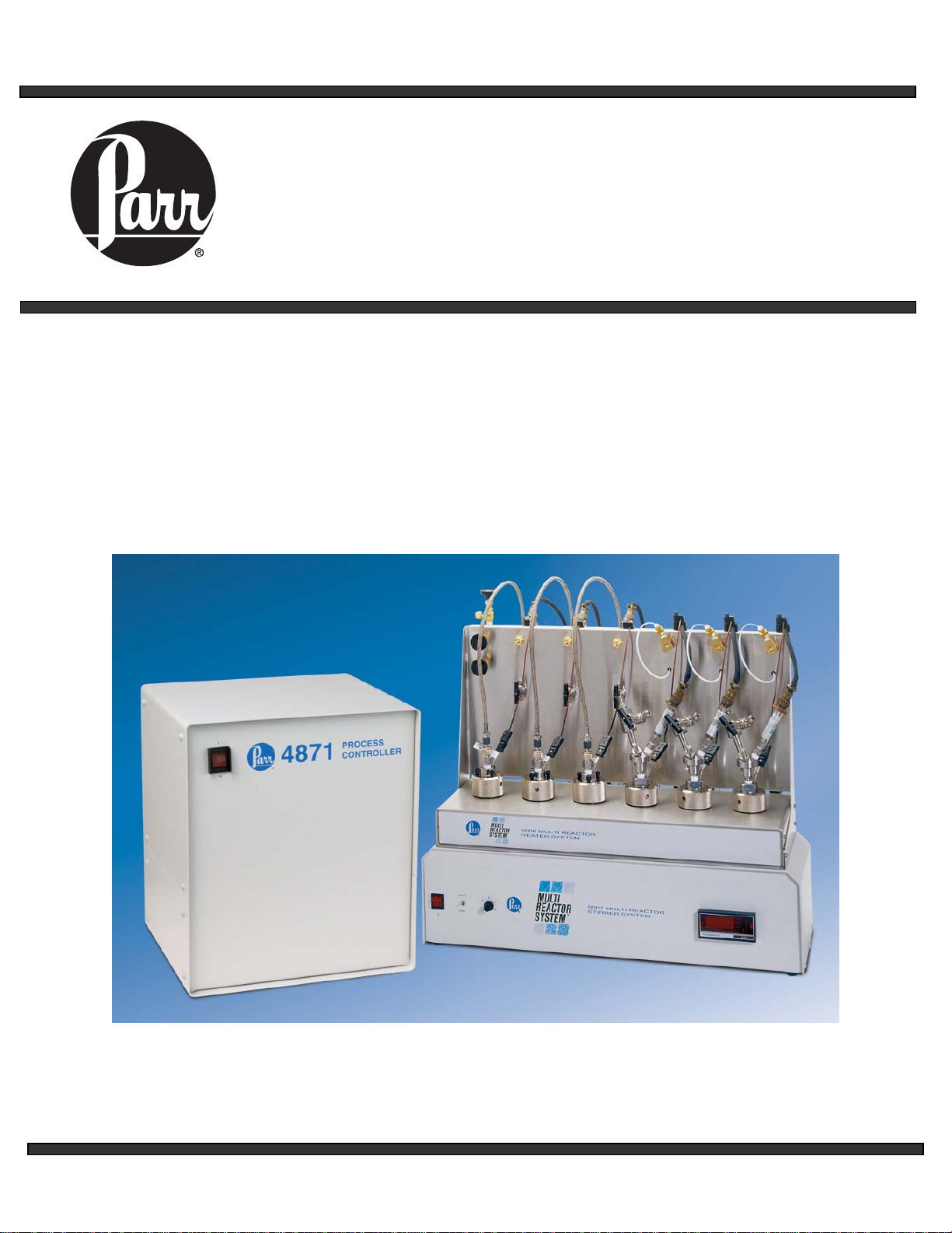
5000
Multiple Reactor System
For Models Produced Prior to July 2013
Page 2

5000 Series Multiple Reactor System
TABLE OF CONTENTS
Customer Service.............................2
Related Instruction ........................... 2
Preface............................................3
Scope...........................................3
Safety Information........................ 3
General Specifications ................. 3
Explanation of Symbols................4
Environmental Conditions ............ 4
Provisions for Lifting and
Carrying........................................ 4
Intended Usage............................ 5
Unpack Carefully.......................... 5
User’s Responsibility.................... 5
Pressure and Temperature Limits 6
Installation......................................7
General Setup Guidelines............7
Installation.................................... 7
Software Installation
and Operation................................. 9
Maintenance ................................... 9
Cleaning.......................................9
Fuses ........................................... 9
Head gaskets...............................9
Rupture Discs............................... 9
Parts List....................................... 10
Diagrams....................................... 12
Related Instructions
The following Parr publications are
also available to further your
understanding of this instrument and
its component parts:
No. Description
201M Limited Warranty
230M General Safety
231M Rupture Disc Instructions
323M Relief Valves
477M CD for 5000 Series MRS
Customer Service
Questions concerning the installation
or operation of this instrument can be
answered by the Parr Customer
Service Department:
309-762-7716
800-872-7720
Fax: 309-762-9453
http://www.parrinst.com
E-mail: parr@parrinst.com
- 2 -
Page 3

5000 Series Multiple Reactor System
PREFACE
Scope
These instructions describe the installation,
operation, and maintenance of the Parr
Series 5000 Multiple Reactor System. They
cover the basic steps to be followed for
installing this system and describe the
function of all standard components. They
are intended to be used in conjunction with
several related instruction sheets listed in
the Table of Contents. This information
describes several components that are
common to most Parr pressure reaction
equipment, and includes safety precautions
and other related information applicable to
all reaction laboratories. The users should
study all of these instructions carefully
before starting to use these vessels so that
they will fully understand the capabilities
and limitations of the equipment.
Safety Information
To avoid electrical shock, always:
1. Use a properly grounded electrical
outlet of correct voltage and current
handling capability.
2. Ensure that the equipment is
connected to electrical service
according to local national electrical
codes. Failure to properly connect
may create a fire or shock hazard.
3. For continued protection against
possible hazard, replace fuses with
same type and rating of fuse.
4. Disconnect from the power supply
before maintenance or servicing.
To avoid personal injury:
1. Do not use in the presence of
flammable or combustible materials;
fire or explosion may result. This
device contains components which
may ignite such material.
2. Refer servicing to qualified
personnel.
General Specifications
Electrical Ratings
Marked Voltages:
230VAC 50/60 Hz 6.5 Amps
115VAC 50/60 Hz 12.5 Amps
Controller ratings are found in the
Operating Instructions for the controller
supplied with your reactor and on the
controller data plate.
Before connecting a controller to an
electrical outlet, the user must be certain
that the electrical outlet has an earth ground
connection and that the line, load and other
characteristics of the installation do not
exceed the following limits:
Voltage: Fluctuations in the line voltage
should not exceed 10% of the rated nominal
voltage shown on the data plate.
Frequency: Controllers can be operated
from either a 50 or 60 Hertz power supply
without affecting their operation or
calibration.
Current: The total current drawn should not
exceed the rating shown on the data plate
on the controller by more than 10 percent.
Thermocouple: Unless otherwise
specified, all Series 5000 Multiple Reactor
Systems operate with a Type-J (IronConstantan) thermocouple. The total
resistance of the thermocouple and the lead
wires should not exceed 100 ohms. If the
resistance of the thermocouple circuit is
higher, it will not function properly.
- 3 -
Page 4
5000 Series Multiple Reactor System
Explanation of Symbols
I
O
~
On position, half power heater switch
Off position
Alternating Current (AC)
This CAUTION symbol may be present on the
Product Instrumentation and literature. If present
on the product, the user must consult the
appropriate part of the accompanying product
literature for more information.
This CAUTION symbol indicates that the surface
may be hot.
Protective Earth (PE) terminal. Provided for
connection of the Protective Earth (green or
green/yellow) supply system conductor.
Earth Ground. Functional earth connection.
NOTE: This connection shall be bonded to
Protective Earth at the source of supply in
accordance with national and local electrical
code requirements.
Environmental Conditions
This instrument is to be used
indoors and requires 3 square
feet of space below the
controller in a well-ventilated
area with convenient access to an electric
outlet.
Operating: 15 °C to 40 °C; maximum
relative humidity of 80% non-condensing.
Installation Category II (overvoltage) in
accordance with IEC 664. Pollution degree
2 in accordance with IEC 664.
Altitude Limit: 2,000 meters.
Storage: -25 °C and 65 °C; 10% to 85%
relative humidity.
Provisions for Lifting and
Carrying
Before moving the instrument, disconnect
all connections from the rear of the
apparatus. Disconnect the grounding strap
between the Heater assembly and Stirrer
assembly. Lift the instrument by grabbing
underneath each corner.
Caution
Do not use in hazardous
atmospheres.
- 4 -
Page 5

5000 Series Multiple Reactor System
Intended Usage
This system has been designed for use as a
high pressure multiple reactor system. It
has been designed, built, and tested to strict
physical and electrical standards. However,
it is the user's responsibility to install and
operate it in conformance with local
pressure and electrical codes.
If this equipment is used in a manner
beyond its intended usage, the protection
provided by the equipment may be
impaired.
Unpack Carefully
Unpack the equipment carefully and check
all the parts against the packing list. If
shipping damage is discovered, report it
immediately to the delivering carriers. The
vessels, heater block, stirrer and controller
may be packed separately for convenience
in shipping, but these parts are easily
reassembled. Examine the components
closely for any loose parts or shipping
damage and be sure to check all layers of
packing materials thoroughly so as not to
overlook any parts which might otherwise
be discarded.
User’s Responsibility
All Parr Reactors and Pressure Vessels are
designed and manufactured with great care
to assure safe operation when used within
their prescribed temperature and pressure
limits. But…the basic responsibility for
safety when using this equipment rests
entirely with the user; who must:
1. Select a reactor or pres sure vessel
that has the capability, pressure rating,
corrosion resistance, and design features
that are suitable for its intended use. Our
engineers will be glad to discuss available
equipment and material options with
prospective users, but the final responsibility
for selecting a reactor or pressure vessel
that will perform to the user's satisfaction in
any particular reaction or test must rest with
the user - not with Parr Instrument
Company.
In exercising the responsibility for the
selection of pressure equipment, the
prospective user is often faced with the
choice between over or under-designed
equipment. The hazards introduced by
under-designed pressure vessels are
readily apparent, but the penalties that must
be paid for over-designed apparatus are
often overlooked. Recognizing these
criteria, our reactors and pressure vessels
are offered in several different styles, each
designed for convenient use in daily
operation within certain temperature and
pressure limits, using gaskets, closures, and
other elements carefully selected for safe
operation within the limits specified for that
design. But in order to preserve the validity
of these designs, all temperature and
pressure limits must be observed, and no
attempt should be made to increase these
limits by making alterations or by
substituting components which are not
recommended by Parr Instrument
Company.
2. Install and operate the equipment
within a suitable barricade, if required, with
appropriate safety accessories and in full
compliance with local safety codes and
rules.
All standard Parr pressure vessels
are provided with either a suitable
relief device or a means to attach one
(typically in the form of a plugged
opening). When a pressure vessel is
delivered without a pressure venting
device, it is the customer’s responsibility
to provide pressure relief in order to
protect the operator and the equipment
from destructive high pressures. If you
need more information or need help
in selecting a proper relief device,
please contact Parr Instrument Company.
3. Establish training procedures to
ensure that any person handling the
equipment knows how to use it properly.
4. Maintain the equipment in good
condition and establish procedures for
periodic testing to be sure the vessel
remains structurally sound.
- 5 -
Page 6
5000 Series Multiple Reactor System
PRESSURE AND
TEMPERATURE LIMITS
Working pressures up to 3000 psi (207
bar) maximum are permissible in these
reactors when constructed of Type 316
Stainless Steel. Contact Parr Customer
Service if your vessel is not constructed
of T316 Stainless Steel and you are
unsure of the pressure and temperature
limit. No attempt should be made to
increase these limits by making
alterations or by substituting
components which are not
recommended by Parr Instrument
Company. It must also be understood
that lower pressure and temperature
limits may be required for modified
reactors and for vessels made of
materials other than T316 Stainless
Steel. Limits for such vessels will be
determined by the physical
characteristics of the material of
construction and will be prescribed on
an individual basis.
Working temperatures up to 300 °C are
permissible in reactors with a standard
2895HCHA flat PTFE gasket. A PTFE
gasket is the recommended choice for
most applications since the PTFE is
inert to most chemicals and it will
provide good seals under repeated
opening and closing if the gasket
temperature does not exceed 300 °C.
The service life of a PTFE gasket will,
however, be reduced considerably if
used at temperatures close to the
300 °C limit.
The maximum working pressure and
temperature for any vessel is governed
by the design of the vessel and the
strength of the material from which it is
constructed. There is also a close
relationship between working pressure
and temperature since the strength of
any material will normally fall off as the
temperature is increased.
Temperature and pressure limits are
also affected by the physical properties
and temperature limits of the gaskets
and seals used in the vessel, and by
any valves, gages, or other fittings
attached to the vessel. Obviously, the
maximum safe operating pressure of
any system can be no higher than that
of its lowest rated component.
Working temperatures up to 220 °C are
permissible in reactors equipped with
fluoroelastomer (FKM) O-ring seals.
The higher the operating temperature
above 200 °C, the shorter the life of the
O-ring will be. Perfluoroeleastomer
(FFKM) O-ring seals have a broad
chemical resistance and be used to
temperatures up to 275 °C.
Unfortunately they are very expensive
and will generally be reserved for unique
applications. Ethylene-propylene (EP)
O-rings can be used to 150 °C and are
recommended for applications such as
ethers, ammonia, and amines which will
rapidly destroy fluoroelastomer O-rings.
The working pressure and temperatures
in these reactors must not exceed the
following maximum limits:
Pressure and Temperature Limits
Vessel
Material
T316SS 3000 psi
T316SS 3000 psi
T316SS 3000 psi
T316SS 3000 psi
Maximum
Pressure
Maximum
Temperature
300 °C PTFE
Flat Gasket
220 °C FKM
O-ring
275 °C FFKM
O-ring
150 °C EP
O-ring
- 6 -
Page 7

5000 Series Multiple Reactor System
INSTALLATION
General Setup Guidelines
The Series 5000 Multiple Reactor
System requires at least 10 square feet
of work space on a sturdy bench or
table in a well ventilated area with
convenient access to an electric outlet.
If the tabletop is not heat resistant it
would be ideal to provide an insulated
pad on which to set the vessels when
hot.
Set the controller near the reactor on a
sturdy bench or table where there is
convenient access to an electrical outlet
capable of carrying up to 20 amperes.
Leave a space of at least twelve inches
between the controller and the heater
block so that the controller will not be
affected by radiant heat.
Installation
The system should be assembled
according to Diagram 1. Please note
that this figure illustrates the rear
view of all components in order to
clearly show the external wiring
details. From the front, the stations are
numbered 1 through 6, from left to right.
- 7 -
Page 8

5000 Series Multiple Reactor System
INSTALLATION (continued)
Diagram 1: Layout Diagram of Multiple Reactor System
Connect the external grounding
strap between the heater and
stirrer assembly.
The A1330E2 Heater Cable
assembly is to be fixed with
screws to prevent access to
live electrical components.
There will be a metal bracket on each
end of the cable with a screw on it.
Unthread the screw and line it up with
the port on the chassis. Then tighten
the screw to fix the cable in place.
Turn on the power switches located on
the front of the controller and the stirrer
assembly. If present, make sure the
stirrer local/remote switch is in the
remote position. If there is no stirrer
local/remote switch present on this unit,
no adjustment is necessary.
- 8 -
Page 9

5000 Series Multiple Reactor System
SOFTWARE INSTALLATION
AND OPERATION
Installation instructions are listed on the
477M CD which accompanied the 5000
MRS System as "MRS_ReadMe.htm".
Operation of the graphical user interface
is listed on the 477M CD which
accompanied the 5000 MRS System as
"Instructions_index.htm".
MAINTENANCE
Cleaning
The chassis, manifold, and valves and
fittings may be cleaned with a damp
cloth. The top and front of the 4871 and
MRS may be cleaned with a lightly
dampened cloth containing mild soap
solution. The heater, the back of the
4871, and the back of the MRS should
not be directly exposed to any liquid
cleaning agent.
Note: Disconnect from power source
before cleaning.
Fuses
The replacement of protective fuses and
backup AA size, 3.6 V battery for the
4871 Controller are the only internal
maintenance procedures that should be
performed by qualified personnel.
Proper fuse rating should be discussed
with Parr Instrument Company
Technical Support. Advanced
troubleshooting instructions can be
obtained by calling Parr Instrument
Company to determine which parts may
need to be replaced or serviced.
Head gaskets
Some extrusion of the PTFE gasket will
occur if the vessels are operated in 200
- 300 °C range. Normally this extrusion
doesn’t preclude reuse of the gasket;
the extruded portion should be removed
with a sharp knife. However, when the
gasket thickness is reduced to half of its
original thickness, it should be replaced.
If an FKM O-ring head gasket is used,
the life of the gasket will be shortened if
the operating temperature is above
200 °C. FFKM O-ring seals may be
used up to 275 °C. Unfortunately they
are very expensive and will generally be
reserved for unique applications. EP Orings may be used up to 150 °C.
Rupture discs
With normal use, rupture discs should
be replaced annually. More frequent
replacement may be necessary
depending on the operating conditions.
- 9 -
Page 10

5000 Series Multiple Reactor System
PARTS LIST
Please see Diagrams section for additional parts.
Cables:
A1330E2 Heater cable assembly, 14-in
A1120E Control cable, 10-ft
A1177E Tachometer harness, 10-ft
A1740E Thermocouple extension wire, type-J, 10-ft
A1623E Pressure harness, 10-ft
A1725E Communication cable to PC, RS-485 to Serial
A1725E2 Communication cable to PC, RS-485 to Ethernet
A1715E Configuration cable, RS-232 to RS-232
A1483EEB Main power cord, North American, 115V
A1483E Main power cord, North American, 230V
A1477E Main power cord, European plug, 230V
A1482E Main power cord, British plug, 230V
1859EEE Main power cord, China plug, 220V
A719E 4871 power cord, North American, 115V
A719EEE 4871 power cord, North American, 220V
1200EEE 4871 power cord, European plug, 230V
1465EEE 4871 power cord, British plug, 230V
1858EEE 4871 power cord, China plug, 220V
A1998E Grounding strap
Pressure Transducers:
A1906EP02 Pressure transducer, 0-200 psi
A1906EP05 Pressure transducer, 0-500 psi
A1906EP10 Pressure transducer, 0-1000 psi
A1906EP20 Pressure transducer, 0-2000 psi
A1906EP30 Pressure transducer, 0-3000 psi
1394HC6 Body for mounting transducer
2683HC Cooling sleeve
827HC O-rings for cooling sleeve
2714HC Hose connection for cooling sleeve
825HC Snap ring for cooling sleeve
Gaskets and seals:
2895HCHA PTFE head gasket for flat gasket vessels
2887HCJV FKM O-ring head g asket for O-ring vessels
2887HCJK FFKM O-ring head gasket for O-ring vessels
Gas Hose assemblies:
A2864HC2 Hose assy, PTFE lined, remote mounted valves
A2864HC3 Flexible metal hose assy, remote mounted valves
HD0012TB03 PEEK tubing, 1/8"OD, head mounted valves
A476A3AA Slip connector, head mounted valves
394HCJE EP O-ring for slip connector, head mo unted valves
- 10 -
Page 11

5000 Series Multiple Reactor System
PARTS LIST (continued)
Rupture disc parts:
526HCPD Rupture disc, 1000 psi
526HCPF Rupture disc, 2000 psi
526HCPG Rupture disc, 3000 psi
581HCPD Rupture disc, 1000 psi, gold faced
581HCPF Rupture disc, 2000 psi, gold faced
581HCPG Rupture disc, 3000 psi, gold faced
49HC2* Orifice cone for rupture disc assembly
527HC Orifice ring for rupture disc assembly
433HC4 Rupture disc body
633HC3 Safety body
Manifold parts:
A525VB Needle valve, 1/8"NPT x 1/8"T
A130VB2 Needle valve, angle, brass, 1/4"NPT x 1/4"T
A541VB Relief valve, 1/8"NPT
Vessel parts:
A129VB Needle valve, 1/4"NPT x 1/4"T
A147VB Needle valve, 1/4"NPT x 1/4"NPT
2898HC2 Adapter for head mounted vessels
2896HC Thermowell, flat gasket vessels, 71 mL, T316
2896HCCH Thermowell, flat gasket vessels, 71 mL, Alloy C-276
2896HC2 Thermowell, O-ring vessels, 71 mL, T316
2896HC2CH Thermowell, O-ring vessels, 71 mL, Alloy C-276
A1742E Thermocouple, T316, 4½” L, 1/16” dia
A2888HC Screw cap, flat gasket vessels, with bolts
1932HC3DE Spare screw cap bolts, flat gasket vessels
2886HC Compression ring, flat gasket vessels
2891HC* Bare head, flat gasket vessel, 71 mL, T316
2893HC* Bare head, O-ring vessel, 71 mL, T316
2890HC* Cylind er, flat gasket vessel, 71 mL, T316
2892HC* Cylinder, O-ring vessel, 71 mL, T316
3011HC* Bare head, flat gasket vessel, 45 mL, T316
3013HC* Bare head, O-ring vessel, 45 mL, T316
3010HC* Cylind er, flat gasket vessel, 45 mL, T316
3012HC* Cylinder, O-ring vessel, 45 mL, T316
2920HC Glass liner, open top, 71 mL
3020HC Glass liner, open top, 45 mL
* Special Materials Available
- 11 -
Page 12

5000 Series Multiple Reactor System
DIAGRAMS
Diagram 1: Layout diagram of 5000 Multiple Reactor System
Diagram 2: 5050/5051 Vessel body diagram, PTFE seal and O-ring seal
Diagram 3: 5050 Vessel, head mounted valves, manual inlet
Diagram 4: 5050 Vessel, head mounted valves, check valve inlet
Diagram 5: Manifold panel for head mounted valves
Diagram 6: Manifold panel for remote mounted valves
Diagram 7: Base assembly with heater and stirrer, 115V
Diagram 8: Base assembly with heaters and stirring assembly, 230V
Diagram 1: Layout Diagram of Multiple Reactor System
- 12 -
Page 13

5000 Series Multiple Reactor System
DIAGRAMS (continued)
5050 Flat Gasket vessel, 75 mL 5050 O-ring seal vessel, 75 mL
5051 Flat Gasket vessel, 45 mL 5051 O-ring seal vessel, 45 mL
Diagram 2: 5050/5051 Vessel Flat Gasket and O-ring
- 13 -
Page 14

5000 Series Multiple Reactor System
DIAGRAMS (continued)
Diagram 3: 5050 Vessel, head mounted valves, manual inlet
Diagram 4: 5050 Vessel, head mounted valves, check valve inlet
- 14 -
Page 15

5000 Series Multiple Reactor System
DIAGRAMS (continued)
Diagram 5: Manifold panel for head mounted valves
- 15 -
Page 16

5000 Series Multiple Reactor System
DIAGRAMS (continued)
Diagram 6: Manifold panel for remote mounted valves
- 16 -
Page 17

5000 Series Multiple Reactor System
DIAGRAMS (continued)
Diagram 6 (continued):
Manifold panel for remote mounted valves
- 17 -
Page 18

5000 Series Multiple Reactor System
DIAGRAMS (continued)
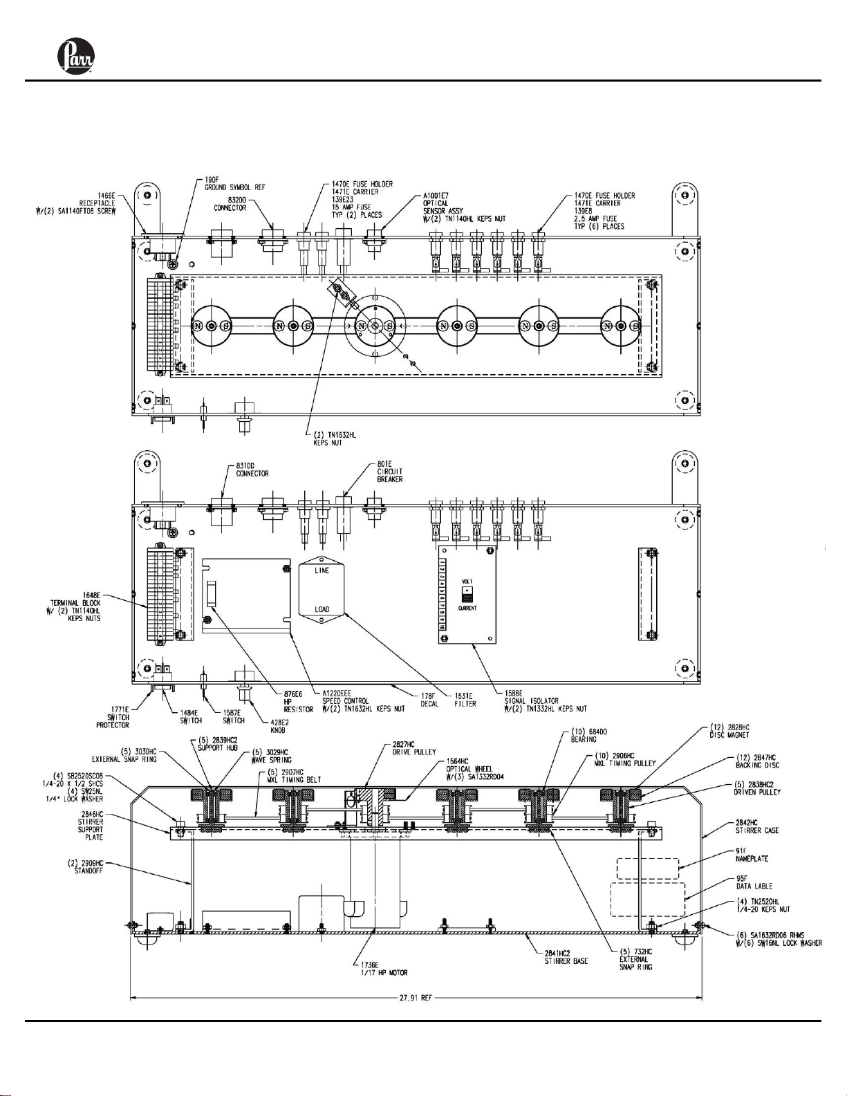
Diagram 7: Base assembly with heaters and stirring assembly, 115V
- 18 -
Page 19
5000 Series Multiple Reactor System
DIAGRAMS (continued)
Diagram 8: Base assembly with heaters and stirring assembly, 230V
- 19 -
Page 20

Revision 02/15/11
PARR INSTRUMENT COMPANY
211 Fifty-Third Street
Moline, Illinois 61265 USA
309/762-7716 800/872-7720
Fax 309/762-9453
http://www.parrinst.com E-Mail: parr@parrinst.com
 Loading...