

Page 1
NO. 567M
Parr Instrument Company
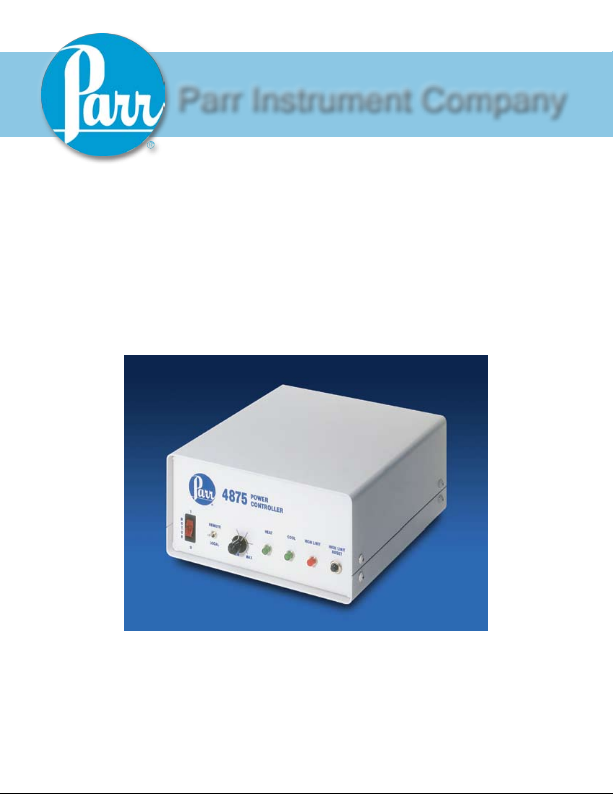
4875
Power Controller
Operating Instruction Manual
Page 2

4875 Power Controller
Pr e f a c e
Related Instructions — 4
Scope — 4
Applications — 4
Explanation of Symbols — 5
Safety Information — 5
Intended Usage — 5
Cleaning & Maintenance — 5
General Specifications — 6
Environmental Conditions — 6
Users Responsibility — 7
Unpack Carefully — 7
In s t a l l a t I o n
General Instructions — 8
4875 Connections — 8
Switches and Indicators — 9
4875 Fuses and Breakers — 10
www.parrinst.com
3
Page 3

4875 Power Controller
Pr e f a c e
re l a t e d In s t r u c t I o n s
The following Parr publications are also included to
further your understanding of this instrument and its
component parts:
No. Description
201M Limited Warranty
sc o P e
These instructions cover the installation and operation
of Parr Model 4875 Power Controller as used with Parr
Laboratory Reactors and Pressure Vessels. They cover
the basic functions provided in each of these controllers.
The users should study the instructions carefully before
using any of these controllers so that they will fully
understand the capabilities of this equipment and the
safety precautions to be observed in its operation.
aP P l I c a t I o n s
Each Series 4875 Power Controller consists of a power
controller completely wired and assembled with appropriate power and safety relays, switches and pilot lights.
These units are designed specifically for use with Parr
reactors and pressure vessels and are to be used only
with Parr equipment.
Controllers furnished with Parr reactors equipped with
variable speed DC motors have a motor switch and a
speed control knob on the front panel of the power controller. Controllers to be used with AC equipment or an
air motor do not have a speed control knob.
Customer Service:
Questions concerning the installation or operation of this instrument
can be answered by the Parr Customer Service Department:
1-309-762-7716 • 1-800-872-7720 • Fax: 1-309-762-9453
E-mail: parr@parrinst.com • http://www.parrinst.com
4
Parr Instrument Company
Page 4

ex P l a n a t I o n o f sy m b o l s
I On position
O Off Position
This CAUTION symbol may be present on the Product Instrumentation
and literature. If present on the product, the user must consult the
appropriate part of the accompanying product literature for more
information.
Protective Earth (PE) terminal. Provided for connection of the protective
earth (green or green/yellow) supply system conductor.
4875 Power Controller
sa f e t y In f o r m a t I o n
To avoid electrical shock, always:
Use a properly grounded electrical outlet of correct 1.
voltage and current handling capability.
Ensure that the equipment is connected to electrical 2.
service according to local national electrical codes.
Failure to properly connect may create a fire or
shock hazard.
For continued protection against possible hazard, 3.
replace fuses with same type and rating of fuse.
Disconnect from the power supply before 4.
maintenance or servicing.
To avoid personal injury:
Do not use in the presence of flammable or 1.
combustible materials; fire or explosion may result.
This device contains components which may ignite
such material.
Refer servicing to qualified personnel.2.
In t e n d e d us a g e
This controller has been designed for use with Parr
Pressure Vessels and Reactors. This controller is
to be used solely with Parr Instrument Company
Heaters, motors, and/ or cooling components. It
has been designed, built, and tested to strict physical
and electrical standards. However, it is the user's
responsibility to install and operate it in conformance
with local pressure and electrical codes.
If the instrument is used in a manner not specified by
Parr Instrument Company, the protection provided by
the equipment may be impaired.
cl e a n I n g & ma I n t e n a n c e
Periodic cleaning may be performed on the exterior
surfaces of the controller with a lightly dampened cloth
containing mild soap solution. All power should be
disconnected and the power cord should be unplugged
when cleaning the controller.
There are no user serviceable parts inside the product
other than what is specifically called out in this manual.
Advanced troubleshooting instructions beyond the
scope of this manual can be obtained by calling Parr
Instrument Company in order to determine which
part(s) may be replaced or serviced.
www.parrinst.com
5
Page 5

4875 Power Controller
ge n e r a l sP e c I f I c a t Io n s
Electrical Ratings
115VAC 50/60 Hz 15.0 Amps
230VAC 50/60 Hz 15.0 Amps
Before connecting to a reactor or heating device,
the user must be sure that the line, load and other
characteristics of the installation do not exceed the
following limits:
Voltage: Fluctuations in the line voltage should not
exceed 10% of the rated nominal supply voltage shown
on the data plate.
Frequency: Controllers can be operated from either
a 50 or 60 Hertz power supply without affecting their
operation or calibration.
Current: The total current drawn should not exceed
the rating shown on the data plate on the controller by
more than 10 percent.
en v I r o n m e n t a l co n d I t I o n s
This instrument is to be used indoors and requires 3
square feet of space below the controller in a wellventilated area with convenient access to an electric
outlet.
Operating: 15 ºC to 35 ºC; maximum relative humidity
of 80% non-condensing. Installation Category II (over
voltage) in accordance with IEC 664.
Pollution degree 2 in accordance with IEC 664.
Altitude Limit: 2,000 meters.
Storage: -25 ºC and 65 ºC; 10% to 85% relative
humidity.
Provisions for Lifting and Carrying
Before moving the instrument, disconnect all
connections from the rear of the apparatus. Lift the
instrument by grabbing underneath each corner.
Caution!
Do not use in hazardous atmospheres.
6
Parr Instrument Company
Page 6

4875 Power Controller
us e r s re s P o n s I b I l I t y
All Parr reactors and pressure vessels are designed and
manufactured with great care to assure safe operation
when used within their prescribed temperature and pressure limits.
But… the basic responsibility for safety when using this
equipment rests entirely with the user; who must:
Select a reactor or pressure vessel that has the 1.
capability, pressure rating, corrosion resistance,
and design features that are suitable for its intended
use. Parr engineers will be glad to discuss available
equipment and material options with prospective
users, but the final responsibility for selecting a reactor or pressure vessel that will perform to the user’s
satisfaction in any particular reaction or test must
rest with the user - not with Parr.
In exercising the responsibility for the selection
of pressure equipment, the prospective user is
often faced with the choice between over or underdesigned equipment. The hazards introduced by
under-designed pressure vessels are readily apparent, but the penalties that must be paid for overdesigned apparatus are often overlooked. Recognizing these criteria, Parr reactors and pressure vessels
are offered in several different styles, each designed
for convenient use in daily operation within certain
temperature and pressure limits, using gaskets, closures, and other elements carefully selected for safe
operation within the limits specified for that design.
But in order to preserve the validity of these designs,
all temperature and pressure limits must be observed, and no attempt should be made to increase
these limits by making alterations or by substituting
components which are not recommended by Parr
Instrument Company.
un P a c k ca r e f u l l y
Unpack the equipment carefully and check all the parts
against the packing list. If shipping damage is discovered, report it immediately to the delivering carriers.
Examine the components closely for any loose parts or
shipping damage and be sure to check all layers of packing materials thoroughly so as not to overlook any parts
which might otherwise be discarded.
Install and operate the equipment within a suitable 2.
barricade, if required, with appropriate safety accessories and in full compliance with local safety codes
and rules.
Establish training procedures to ensure that any 3.
person handling the equipment knows how to use it
properly.
Maintain the equipment in good condition and es-4.
tablish procedures for periodic testing to be sure the
vessel remains structurally sound.
www.parrinst.com
7
Page 7

4875 Power Controller
139E10, FUSE, .25 AMP
90VDC 1/8HP
In s t a l l a t I o n
ge n e r a l In s t r u c t I o n s
Set the controller near the reactor on a sturdy bench or
table where there is convenient access to an electrical
outlet capable of carrying up to 15 amperes. Leave a
space of at least twelve inches between the controller
and the heater of the reactor so that the controller will
not be affected by radiant heat.
Refer to applicable Process Controller Operating
Manual for specific installation instructions.
4875 co n n e c t I o n s
Labeled connections are provided on the rear panel of
the controller.
Parr Cooling Only:
The Parr Cooling output connector is to be used only
with Parr Instrument Company cooling solenoid valve
assemblies supplied with the appropriate cooling power
cord.
Parr Heating Only:
The Parr Heating output connector is to be used only
with Parr Instrument Company heater assemblies
supplied with the appropriate heater power cord.
Motor:
Secure the clamp on motor cord to the
controller with the provided screw next to
the motor socket for safety purposes.
The Motor output connector is to be used only with
Parr Instrument Company motor assemblies supplied
with the appropriate motor power cord.
The Power Control connection is for connection to the
Process Controller.
The Power Input connection is for connection to a
suitable power source. Only use Parr cord sets supplied
with the controller. Take care to position the controller
so that the power cord can easily be accessed if power
needs to be removed from the system.
8
4875 Power Controller Rear Panel
Parr Instrument Company
Page 8

4875 Power Controller
sw I t c h e s a n d In d I c a t o r s
The motor controls consist of an on-off switch, a speed
control knob and, local remote switch. The speed con-
trol knob should be turned down to a minimum setting
before turning on the motor switch to minimize electrical surges within the speed control unit.
The motor on-off switch switches on and off power to
the motor output.
The local remote switch, switches between local control using the speed control knob and remote control
using a PC.
We do not include the speed control knob, local remote
switch or motor switch when the reactor is equipped
with an air motor for stirring or when the controller is
created for use with a non-stirred vessel.
The heat indicator shows that power is being sent to the
heater. During a process, this indicator may light intermittently as the temperature approaches the set point on
the controller. This a normal occurrence of using time
proportioned heating with a PID controller.
The cool indicator shows that power is being sent to the
solenoid valve module. During a process, this indicator
may light intermittently as the temperature approaches
the set point on the controller. This is a normal occurrence of using time proportioned heating with a PID
controller.
The high limit indicator light will indicate if the
controller receives a signal that a high temperature or
pressure limit has been reached and the high limit reset
relay has opened. When the light comes on, the user
must find the source of the problem, correct it, and then
manually reset the system using the high limit reset button on the front of the controller.
A high-limit reset is provided to shut-off power to
the heater whenever any of the alarm conditions are
reached. It can be actuated either by the high temperature alarm settings in the basic control module, or by
the high pressure limit settings in any of the optional
modules installed in the controller. When tripped, this
breaker must be reset manually using the push button
on the front panel. Often the high limit reset will trip
when the process controller power has been cycled.
4875 Power Controller Front Panel
www.parrinst.com
9
Page 9

4875 Power Controller
139E10, FUSE, .25 AMP
90VDC 1/8HP
4875 fu s e s a n d br e a k e r s
Warning:
Unplug unit before servicing. For continued
protection against possible hazard, replace
fuses with same type and rating of fuse.
The motor reset fuse provides overload protection for
0-90VDC motors. This is a re-settable breaker designed
to protect the motor if it becomes overloaded. The
breaker will have a rating selected to match the motor
on the apparatus.
A lighted fuse holder provides protection for
0-180VDC motors. A light on the fuse holder will
indicate the motor has become overloaded and the fuse
burned out. The fuse rating will be selected to match the
motor on the apparatus.
A heating fuse, or two heater fuses on 230V models,
is mounted on the back panel. These are fast-acting,
250VAC, 15A fuses intended to protect the controller if
an over current fault occurs within the heater assembly.
A light on the fuse holder(s) will indicate if a fuse has
burned out
A cooling fuse, or two cooling fuses on 230V models,
is mounted on the back panel. These are fast-acting,
250VAC, .25A fuses to protect the controller if an over
current fault occurs within the cooling solenoid assembly.
10
4875 Power Controller Rear Panel
Parr Instrument Company
Page 10

Revision 02/11/10
P
arr Instrument Company
211 53rd Street
Moline, Illinois 61265 USA
Phone: 1-309-762-7716 or 1-800-872-7720
Fax: 1-309-762-9453
E-mail: parr@parrinst.com
http://www.parrinst.com
 Loading...