

Page 1

No. 519M
r
Parr Instrument Company
4857
Process Controlle
Operating Instruction Manual
Page 2

4857 Reactor Controllers
TABLE OF CONTENTS
Related Instructions .............................2
Customer Service.................................2
Preface 3
Scope...................................................3
Applications..........................................3
Explanation of Symbols........................4
Safety Information................................4
Intended Usage....................................4
General Specifications.........................5
Environmental Conditions....................5
User’s Responsibility............................6
Unpack Carefully..................................6
Installation 7
General Instructions.............................7
Connections.........................................7
Switches and Indicators 8
4857 Switches and Indicators..............8
Protective Fuses 8
4857 Fuses ..........................................8
Model 4857 Process Controller
Specifications 9
Temperature Control Parameters.......9
Software Installation 10
Before Software Installation.................10
Minimum PC Requirements.................10
CalGrafix Installation Instructions.........10
Install USB Drivers...............................10
Single Reactor......................................11
Two Reactors.......................................12
Operation of the 4857 Controller 13
Running CalGrafix................................13
Restoring Factory Defaults...................15
Finding the Active COM Port................16
Setting the Active COM Port................16
Changing the Name of a Module .........17
Autotuning............................................18
Module 1: Temperature Control Module
Setpoint Adjustment.............................19
High Temperature Alarm Adjustment...20
Changing PID Settings.........................21
Temperature Programmer....................22
Module 2: Pressure Display and
High Pressure Alarm
Alarm Adjustment.................................25
Module 3: Tachometer
Stirring Speed Adjustment...................26
Module 4: Optional Module
Optional Module...................................27
Data Logging 28
Creating a Chart ..................................28
Exporting Data from a Chart................30
Solenoid Valve Module 30
Cleaning and Maintenance 31
Fuses...................................................31
Access to Controller Cabinet...............31
Controller and Circuit Diagrams 32
Parts for the 4857 Controller 35
Related Instructions
The following Parr publications are also
included to further your understanding of this
instrument and its component parts:
No. Description
201M Limited Warranty
521M 4857 Process Controller CD
547M 4857 CalGrafix CD
567M 4875 Power Controller Operating
Instructions
Customer Service
Questions concerning the installation or
operation of this instrument can be answered
by the Parr Customer Service Department:
309-762-7716
800-872-7720
Fax: 309-762-9453
www.parrinst.com
parr@parrinst.com
- 2 -
Page 3

4857 Reactor Controllers
PREFACE
Scope
These instructions cover the installation and
operation of Parr Model 4857 Process Controller
as used with Parr Laboratory Reactors and
Pressure Vessels. They cover the basic
functions provided in each of these controllers.
The users should study the instructions carefully
before using any of these controllers so that they
will fully understand the capabilities of this
equipment and the safety precautions to be
observed in its operation.
Applications
Each Series 4857 Process Controller consists of
a packaged temperature control unit completely
wired and assembled with appropriate power
and safety relays, switches and pilot lights.
These units are designed specifically for use
with Parr reactors and pressure vessels and are
to be used only with Parr equipment.
Controllers furnished with Parr reactors
equipped with variable speed DC motors have a
motor switch and a speed control knob on the
front panel of the power controller. Controllers to
be used with AC equipment or an air motor do
not have a speed control knob.
- 3 -
Page 4
Explanation of Symbols
4857 Reactor Controllers
I
O
This CAUTION symbol may be present on the Product Instrumentation
Safety Information
To avoid electrical shock, always:
1. Use a properly grounded electrical outlet of
correct voltage and current handling capacity.
2. Ensure that the equipment is connected to
electrical service according to local national
electrical codes. Failure to properly connect may
create a fire or shock hazard.
3. For continued protection against possible
hazard, replace fuses with same type and rating
of fuse.
4. Disconnect from the power supply before
maintenance or servicing. The power supply
cord of the equipment is the main disconnect
device.
To avoid personal injury:
1. Do not use in the presence of flammable or
combustible materials where fire or explosion
may result. This device contains components
which may ignite such materials.
2. Refer servicing to qualified personnel.
On position
Off position
and literature. If present on the product, the user must consult the
appropriate part of the accompanying product literature for more
information.
Protective Earth (PE) terminal. Provided for connection of the
Protective Earth (green or green/yellow) supply system conductor.
Intended Usage
This controller has been designed for use with
Parr Pressure Vessels, Reactors and Power
Controllers. It has been designed, built, and
tested to strict physical and electrical standards.
However, it is the user's responsibility to install
and operate it in conformance with local
pressure and electrical codes.
If the instrument is used in a manner not
specified by Parr Instrument Company, the
protection provided by the equipment may be
impaired.
- 4 -
Page 5

4857 Reactor Controllers
General Specifications
Electrical Ratings:
115VAC 50/60 Hz 3.0 Amps
230VAC 50/60 Hz 3.0 Amps
Before connecting to a reactor or heating device,
the user must be sure that the line, load and
other characteristics of the installation do not
exceed the following limits:
Voltage: Fluctuations in the line voltage should
not exceed 10% of the rated nominal supply
voltage shown on the data plate.
Frequency: Controllers can be operated from
either a 50 or 60 Hertz power supply without
affecting their operation or calibration.
Current: The total current drawn should not
exceed the rating shown on the data plate on
the controller by more than 10 percent.
Thermocouple. Unless otherwise specified, all
Series 4857 Process Controllers operate with a
Type J (iron-constantan) thermocouple. The
total resistance of the thermocouple and the
lead wires should not exceed 100 ohms. If the
resistance of the thermocouple circuit is higher,
it will not function properly.
Environmental Conditions
This instrument is to be used indoors and
requires 3 square feet of space below the
controller in a well-ventilated area with
convenient access to an electric outlet.
Operating: 15°C to 30°C; maximum relative
humidity of 80% non-condensing.
Installation Category II
(overvoltage) in accordance with
IEC 664. Pollution degree 2 in
accordance with IEC 664.
Altitude Limit: 2,000 meters.
Storage: -25°C and 65°C; 10% to 85%
relative humidity.
Provisions for Lifting and Carrying
Before moving the instrument, disconnect all
connections from the rear of the apparatus. Lift
the instrument by grabbing underneath each
corner.
Caution
Do not use in hazardous
atmospheres.
- 5 -
Page 6

4857 Reactor Controllers
User’s Responsibility
All Parr Reactors and Pressure Vessels are
designed and manufactured with great care to
assure safe operation when used within their
prescribed temperature and pressure limits.
But…the basic responsibility for safety when
using this equipment rests entirely with the user;
who must:
1. Select a reactor or pressure vessel that has
the capability, pressure rating, corrosion
resistance, and design features that are
suitable for its intended use. Parr engineers
will be glad to discuss available equipment
and material options with prospective users,
but the final responsibility for selecting a
reactor or pressure vessel that will perform to
the user's satisfaction in any particular
reaction or test must rest with the user - not
with Parr.
In exercising the responsibility for the
selection of pressure equipment, the
prospective user is often faced with the
choice between over- or under-designed
equipment. The hazards introduced by
under-designed pressure vessels are readily
apparent, but the penalties that must be paid
for over-designed apparatus are often
overlooked. Recognizing these criteria, Parr
reactors and pressure vessels are offered in
several different styles, each designed for
convenient use in daily operation within
certain temperature and pressure limits, using
gaskets, closures, and other elements
carefully selected for safe operation within the
limits specified for that design. But in order to
preserve the validity of these designs, all
temperature and pressure limits must be
observed, and no attempt should be made to
increase these limits by making alterations or
by substituting components which are not
recommended by Parr Instrument Company.
2. Install and operate the equipment within a
suitable barricade, if required, with
appropriate safety accessories and in full
compliance with local safety codes and rules.
All standard Parr pressure vessels are provided
with either a suitable relief device or a means to
attach one (typically in the form of a plugged
opening). When a pressure vessel is delivered
without a pressure venting device, it is the
customer’s responsibility to provide pressure
relief in order to protect the operator and the
equipment from destructive high pressures. If
you need more information or need help in
selecting a proper relief device, please contact
Parr Instrument Company.
3. Establish training procedures to ensure that
any person handling the equipment knows
how to use it properly.
4. Maintain the equipment in good condition and
establish procedures for periodic testing to be
sure the vessel remains structurally sound.
Unpack Carefully
Unpack the equipment carefully and check all
the parts against the packing list. If shipping
damage is discovered, report it immediately to
the delivering carriers. Examine the
components closely for any loose parts or
shipping damage and be sure to check all layers
of packing materials thoroughly so as not to
overlook any parts which might otherwise be
discarded.
- 6 -
Page 7
4857 Reactor Controllers
INSTALLATION
General Instructions
Set the controller near the reactor on a sturdy
bench or table where there is convenient access
to an electrical outlet capable of carrying up to
20 amperes. Leave a space of at least twelve
inches between the controller and the heater of
the reactor so that the controller will not be
affected by radiant heat.
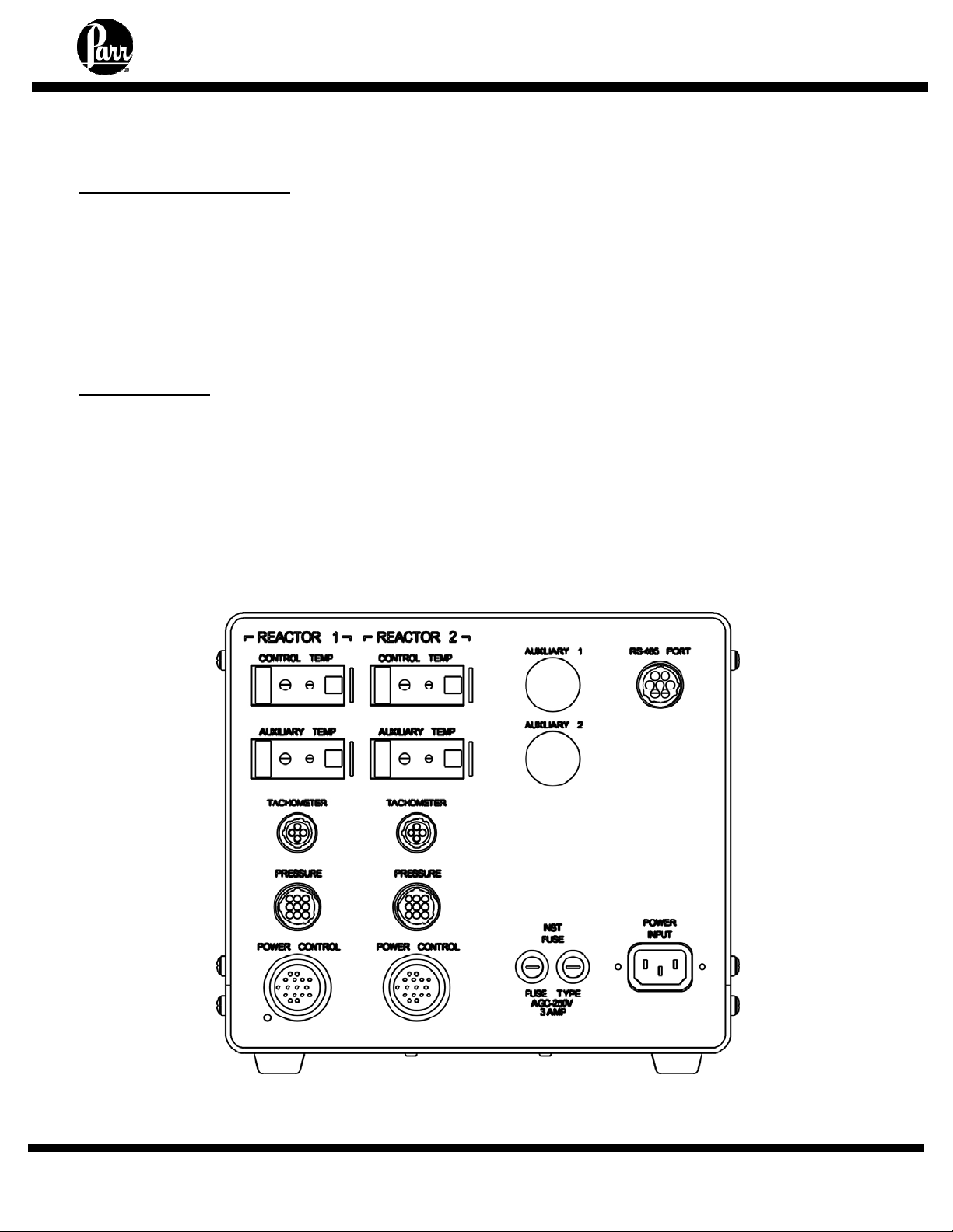
Connections
Labeled connections are provided on the rear
panel of each controller.
The Control Temp connection is for the internal
reactor thermocouple or RTD harness.
The Auxiliary Temp connection is for a
secondary thermocouple or RTD harness.
The Tachometer connection is for the optical
sensor harness.
The Pressure connection is for the reactor
pressure sensor harness.
The Auxiliary connection is for an optional
input.
The Power Control connection is for connection
to the 4875 Power Controller.
The RS-485 PORT connection is for
communication to PC.
- 7 -
Page 8
4857 Reactor Controllers
SWITCHES AND INDICATORS
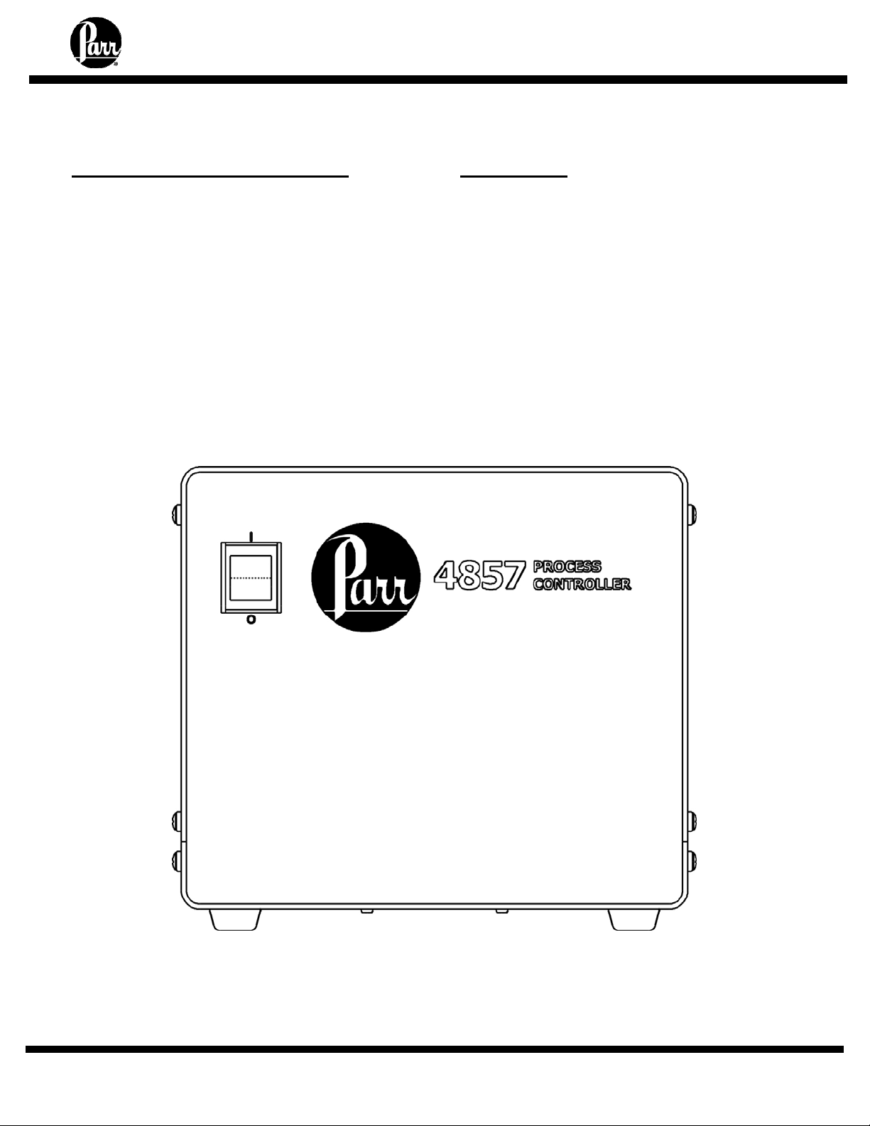
4857 Switches and Indicators
The Main Switch is a manual, two-position,
illuminated switch which will cut off power to the
controller. The light indicates power the power is
on. Take care to position the controller such that
the main power switch may be accessed easily
when the controller needs to be disconnected.
PROTECTIVE FUSES
4857 Fuses
Two instrument fuses are mounted on the
back panel. These are Fast-acting, 250VAC, 3.0
amp fuses, intended to protect the internal
circuitry of the controller.
4857 Process Controller Front Panel
- 8 -
Page 9
4857 Reactor Controllers
MODEL 4857 PROCESS CONTROLLER SPECIFICATIONS
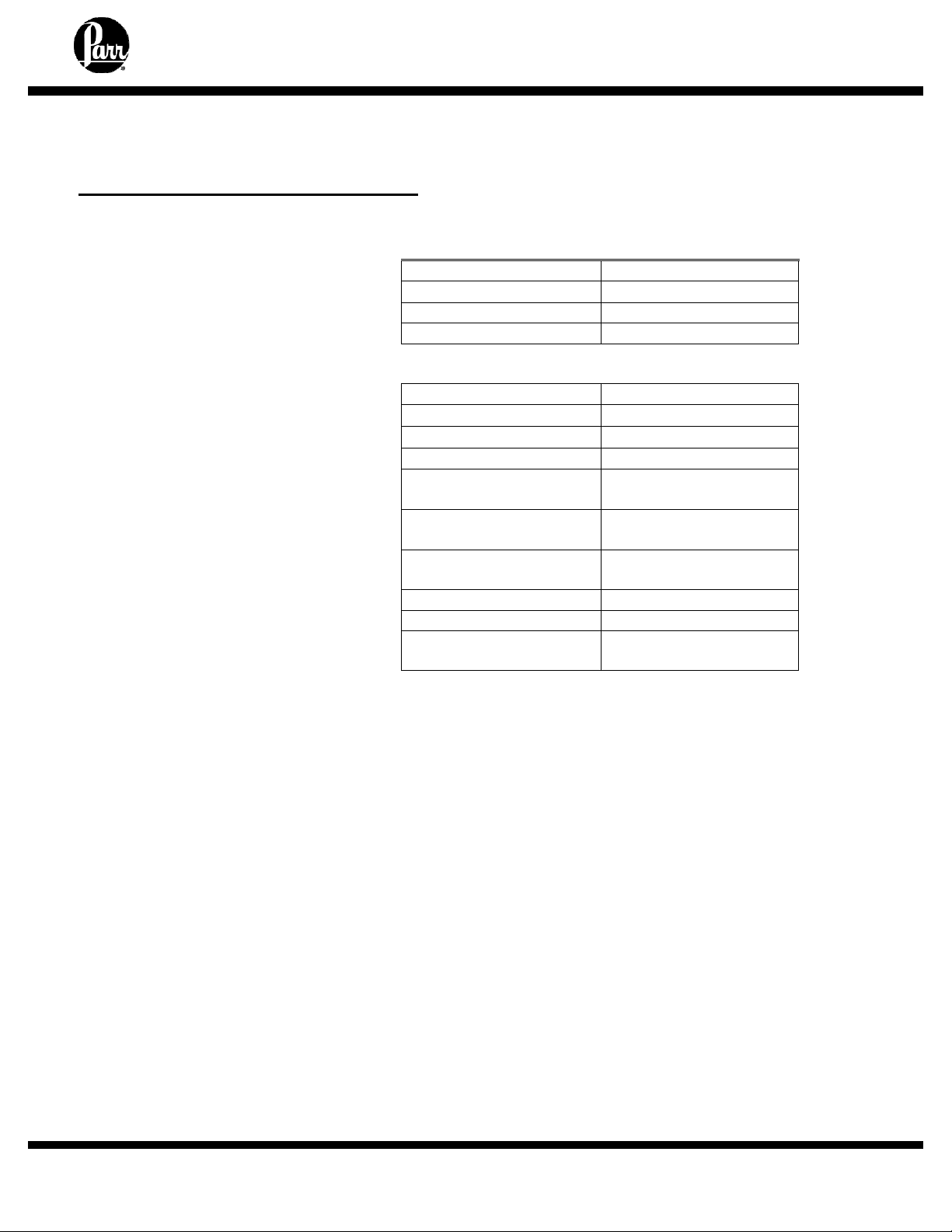
Temperature Control Parameters
To facilitate start up with reasonably
good PID control parameters for heating
and cooling, all 4857 Process
Controllers are programmed at the
factory with the temperature control
settings shown on the right.
Output 1 on these controllers drives the
heater. Output 2 can be used to
activate a cooling system. Control
parameters can be set independently for
each of these outputs.
Module 1: Temperature Control
Cycle time 2 seconds
Proportional Band
Integral Time 5 min
Derivative Time 25 sec
Input thermocouple
Operating range
Display resolution
Setpoint resolution
System accuracy
Control action
Control output 1
Control output 2
Operating voltages
Maximum switching
load
25 °C
Type J
0 to 800 °C
.1 °C
.1 °C
+/- 0.1% FS
+/- 1°C typical
Three term PID control
plus limit control
15 amp @ 115V,
15 amp @ 230V
0.25 amp
115 and 230 VAC
15 amp @ 115 VAC
15 amp @ 230 VAC
- 9 -
Page 10

4857 Reactor Controllers
SOFTWARE INSTALLATION OF THE 4857 PROCESS CONTROLLER
Before Software Installation
The CalGrafix software should be installed on a
PC which has not previously been used to run
software for Cal applications. The PC should
meet at least the minimum system requirements.
Minimum PC Requirements
As a general requirement, we would
recommend a minimum of Pentium 450MHz
with 256MB RAM, Windows
screen resolution, 1024 x 768. 100MB of
free hard drive space is more than
sufficient.
TM
2000/XP and
Installation Instructions:
Note: Temperature control modules have been set to park mode as a precaution against
heating before connection to a PC. Following these installation instructions will reset the
parameters for these modules to allow heating and stirring.
Do not connect the 4857 to the PC until the following installation has been completed.
CalGrafix Installation Instructions:
1. Locate the 547M CalGrafix CD and insert it into the CD drive.
2. From the CD, open the setup.exe file to run the installation program.
3. Follow on screen instructions to complete installation.
Install USB Drivers (for USB cables only)
Note: If using serial port communication, no driver installation is required.
1. Insert the 521M CD.
2. Attach USB Cable to PC. Do not connect cable to 4857 Process Controller yet.
3. The "Add new hardware" wizard should appear. Click "Next."
4. Select "Search for the best driver for your device." Click "Next."
5. The wizard will then ask the location of the driver. With the Parr 521M CD in the CD-
drive, select "CD-ROM drive" and click "Next."
6. The wizard should find the "\FTDIBUS.INF" file. If it does not find the driver, select
“specify driver location” and find the driver at: ”/installation/USB-SerialPortAdapter/BBElec/USOTL4/VISTA_XP or WIN98_ME”. Click "Next."
7. The wizard should install the driver. Click "Next."
8. The wizard will also find the USB Serial Port. This should be installed in the same
manner as the previous driver. When it is finished, click "Finish."
- 10 -
Page 11
4857 Reactor Controllers
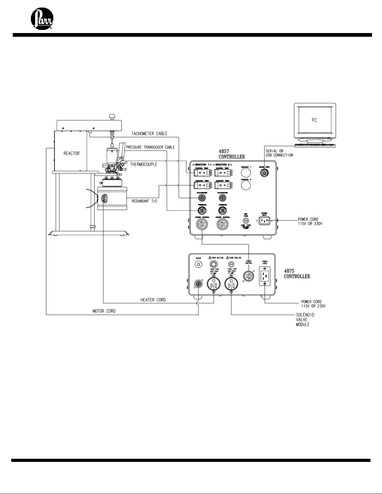
Connections between single Reactor,
4857 Process Controller, and single 4875 Power Controller
Diagram 1: Schematic Diagram of Connections to
4857 Process Controller for control of
a single reactor with 4875 Power Controller
- 11 -
Page 12
4857 Reactor Controllers
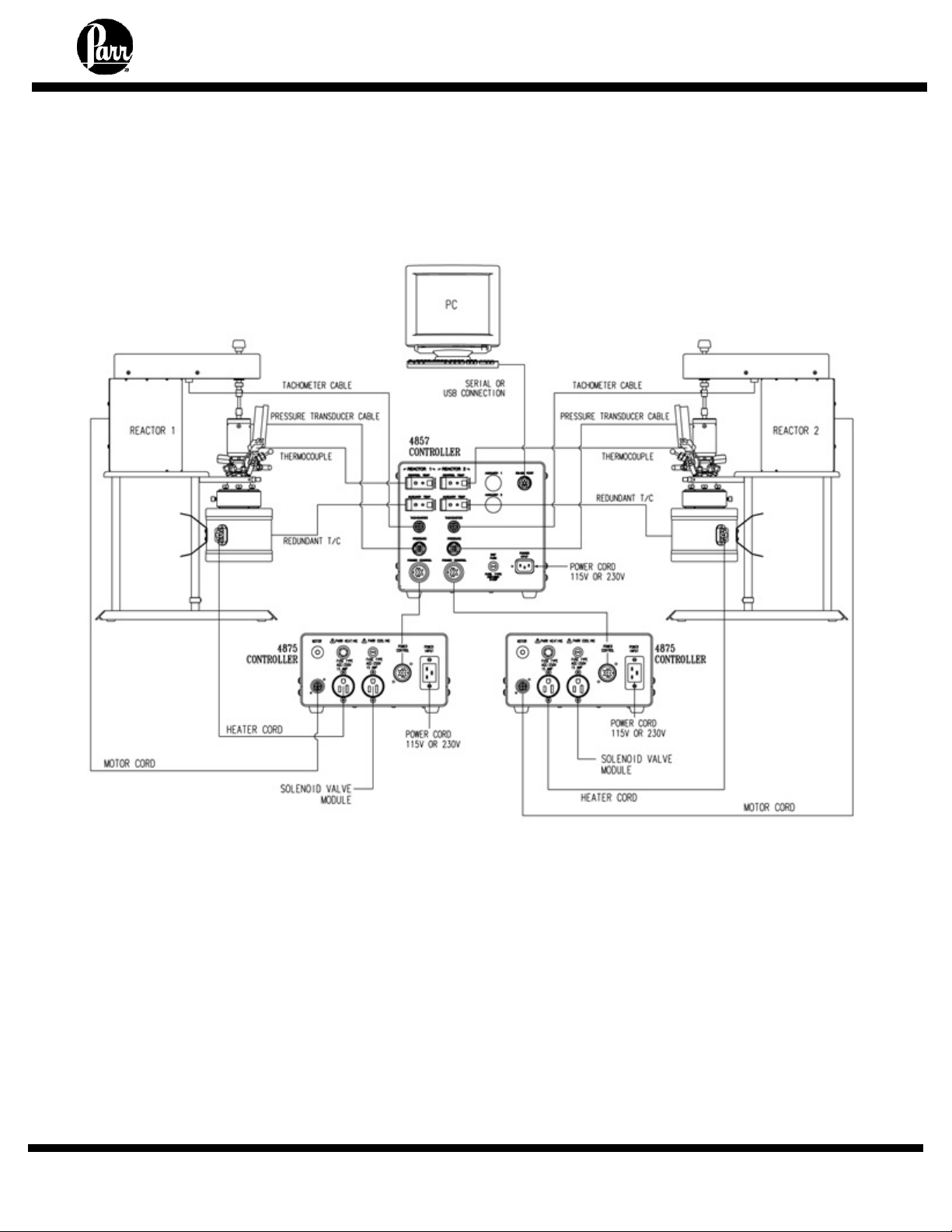
Connections between two Reactors,
4857 Process Controller, and dual 4875 Power Controllers
Diagram 2: Schematic Diagram of Connections to
4857 Process Controller for control of
two reactors with two 4875 Power Controllers
- 12 -
Page 13

4857 Reactor Controllers
OPERATION OF THE 4857 PROCESS CONTROLLER
Before operation
Be certain to set the power settings on the PC such that it will not hibernate or time out after a period of time.
After CalGrafix and the USB Drivers are installed on the PC, it is OK to attach the 4857 to the
PC according to diagram 1 or diagram 2 and turn it on.
Run the CalGrafix Program
1. The CalGrafix Program has been added to the program list. Access it at:
"Start >> Programs >> CalGrafix >> CalGrafix"
Accessing the CalGrafix program
through the Start menu
2. Click on the small controller faceplate icon on the menu bar, or select "File >> New
Instrument".
3. CalGrafix will attempt to locate the 4857 Process Controller.
a. If the 4857 is not shown in the device box, click "browse" and
select the COM port being used by the 4857. Then click the
"browse" button again. Repeat this step until the device appears
in the device box. Click OK.
b. The 4857B will find two devices when the proper COM port is
selected. Using the Shift key, select both devices and click OK.
c. If there is uncertainty for which COM port is being used, see the
section on "Finding the active COM port" in this manual.
Locating the 4857 with the Device Box
- 13 -
Page 14

4857 Reactor Controllers
OPERATION OF THE 4857 PROCESS CONTROLLER (CONTINUED)
Run the CalGrafix Program (continued)
4. A graphic of the 4857 Control Module will be displayed. The base module is illustrated in the
center with modules 1-4 on either side. The 4857B will have two graphics displayed instead
of one.
4857 Main Control Screen
5. The process may be controlled according to the instructions regarding operation of
the individual modules.
During initial installation, Modules 1 and 3 are set to Park for safety. See instructions on
Modules 1 and 3 to reset mode from Park to the PID (for Module 1) and PI (for Module 3).
6. Save the application file to the PC. Select “File” >> “Save As”, and save the file in an
appropriate place. One convenient place for this would be located at "C:\Program Files\CAL
Controls\CALGrafix". This file may be used later to restore the controller to its current
defaults.
7. CalGrafix may be exited by selecting "File >> Quit".
- 14 -
Page 15

4857 Reactor Controllers
OPERATION OF THE 4857 PROCESS CONTROLLER (CONTINUED)
Factory Defaults
Restoring the 4857 to it factory defaults is relatively simple. There are is a file on the 521M CD
which may be copied to the PC at "\Factory Defaults\factorydefaults.dev".
Opening the .dev file with CalGrafix will restore the controller settings in the 4857 Process
Controller.
Restoring Factory Default Values
1. Set the active COM port to COM7. If you are unsure of how to do this, see the section on
"Setting the active COM port" in this manual.
2. Open the CalGrafix program in the usual manner. Connect to the 4857 Controller by
clicking on the small controller faceplate icon on the menu bar, or selecting "File >>
New Instrument".
3. If the 4857 is not shown in the device box, click "browse" and select COM7.
4. When the CalGrafix program finds the 4857, select “File” >> “Open.”
5. Locate the factorydefaults.dev file on the 521M CD at "\Factory
Defaults\factorydefaults.dev". Select open.
6. CalGrafix will ask which values to write. Check the boxes of "Modules 1-3". Click OK. If you
have a 4th module which needs to be reset, contact Parr Technical Support .
7. CalGrafix will write the application data from the default file to the 4857.
- 15 -
Page 16

4857 Reactor Controllers
OPERATION OF THE 4857 PROCESS CONTROLLER (CONTINUED)
Finding the Active COM Port
When using CalGrafix to connect to the 4857 Process Controller, it is advantageous to know
which COM port the PC is using to connect to the controller. The following instructions detail
how to find the active COM port with Windows 2000 as the operating system.
1. Connect the 4857 to the PC using the provided cable and turn the 4857 on.
2. On the Desktop, right click on "My Computer" and select "Properties."
3. Switch to the "Hardware" tab and click on "Device Manager."
4. The Device Manager should come up. Expand the "Ports (COM & LPT)" box.
5. The COM ports which are in use should be listed here. Make a note of the ones listed; one
of these should be the one to instruct CalGrafix to use to connect to the 4857.
Setting the Active COM Port
In some instances (such as restoring Factory Defaults) it is necessary to instruct the PC which
COM port to use for connection to the 4857. You will need Administrator privileges in order to
set the active COM port.
1. Connect the 4857 to the PC using the provided cable and turn the 4857 on.
2. On the Desktop, right click on "My Computer" and select "Properties."
3. Switch to the "Hardware" tab and click on "Device Manager."
4. The Device Manager should come up. Expand the "Ports (COM & LPT)" box.
5. Right click on the active COM port and select "Properties." Tab to "Port Settings" and click
on "Advanced."
6. Set the COM port using the "COM port number" box. Click OK and exit the device manager.
- 16 -
Page 17

4857 Reactor Controllers
OPERATION OF THE 4857 PROCESS CONTROLLER (CONTINUED)
Changing the Name of a Module
1. Right click on controller image.
2. Select properties and select "Properties >> Module 1", or whichever module you would like
to change.
3. Expand "Module Settings".
4. Change the name from "Module 1" to another name such as "Temperature" and
click OK.
- 17 -
Page 18

4857 Reactor Controllers
OPERATION OF THE 4857 PROCESS CONTROLLER (CONTINUED)
Autotuning
The 4857 Process Controller is equipped with default PID values from the factory designed to
give reasonable temperature control across a wide temperature range. Autotuning is not
recommended unless the system has exhibited poor control using the default PID values.
The 4857 Process Controller may be auto tuned at setpoint. Using the other types of auto tune
(not the tune at setpoint) will likely result in an error.
1. Bring the system to the desired setpoint for the process by adjusting the setpoint of the
controller. Let the system come to equilibrium and hold steady at the setpoint for at least ten
minutes. This step may require that the temperature overshoot or undershoot significantly
with existing PID values.
2. Right click on the main screen, select "Properties >> Module 1", and then change the mode
on "Autotune Setting" to "ATSP".
3. On the main screen, Module 1 should flash “ATSP" at the bottom. This indicates that the
controller is tuning.
4. During the auto tune, the temperature may rise or fall by a few degrees. This is normal.
When the auto tune is complete, the “ATSP" will stop flashing. The temperature should
remain at the setpoint upon completion of the auto tune.
5. Check the PID settings in Module 1 after the autotune. Values which were changed by the
auto tune will have an “A” before the value.
6. If the auto tune selected a value of less than 5 for either the CyC.t or CyC.2, change this
value back to 5. If it selected a value larger than 5, this is OK.
- 18 -
Page 19

4857 Reactor Controllers
MODULE 1: TEMPERATURE CONTROL MODULE
Setpoint Adjustment
Before carrying out an autotune or run with the default settings to ensure the system is safe to
operate at the setpoint value.
1. Right click on controller image.
2. Select properties and select programmer and set-points.
3. Expand (+) setpoints menu.
4. Enter Module 1 - Setpoint 1 value for the required module (click out of value box once
setting entered to ensure value is accepted)
5. Apply setting and click OK
6. New setpoint is now written to the controller and should be visible on controller image.
- 19 -
Page 20

MODULE 1: TEMPERATURE CONTROL MODULE (CONTINUED)
High Temperature Alarm Adjustment
The high temperature alarm on Module 1 may also be adjusted.
1. Right click on controller image.
2. Select properties and select "Properties >> Module 1".
4857 Reactor Controllers
3. Expand "Module 1 - Setpoint 3 control".
4. Enter Module 1 - Setpoint 3 value for the required module (click out of value box once
setting entered to ensure value is accepted)
5. Apply setting and click OK.
6. New setpoint is now written to the controller. The high temperature alarm setpoint will not be
visible on the main controller screen.
- 20 -
Page 21

MODULE 1: TEMPERATURE CONTROL MODULE (CONTINUED)
Changing PID Settings, Changing from PARK to PID Mode
Installation Note:
During initial installation, the mode on Module 1 will need to be changed.
Right click on the controller image and select “Properties >> Module 1.”
Expand (+) Module1 – Setpoint1 Control, and change mode from Park to PID.
1. Right click on controller image.
2. Select properties and select "Properties >> Module 1".
4857 Reactor Controllers
3. Expand "Module 1 - Setpoint1 control".
4. The "Mode" value may be changed to PID. Also, the values for Band, Integral Time, and
Derivative Time may be adjusted here as well to suit the process.
5. Apply setting and click OK.
- 21 -
Page 22

4857 Reactor Controllers
MODULE 1: TEMPERATURE CONTROL MODULE (CONTINUED)
Temperature Programmer
The temperature programmer may be used as an alternative to set point control. This feature is
particularly useful when more complex temperature profiles are required.
Creating a Program:
1. From the main screen, click on the "Edit Programs button."
2. The Program window will appear. Click on "Programmer >> New Program."
3. You may add your first step to the program by right clicking on the Program window and
selecting "Add Segment >> Ramp / Soak / Step."
4. The program will ask the number of segments to add. Add the number of segments
necessary for the process and click OK.
- 22 -
Page 23

4857 Reactor Controllers
MODULE 1: TEMPERATURE CONTROL MODULE (CONTINUED)
Temperature Programmer (continued)
5. You may select the segment type by clicking on the box next to "Segment Type." Most
temperature programs will make use only of the Ramp and the Soak types. A Soak step will
hold the temperature at its programmed level for the specified period of time. A Ramp step
will increase the setpoint from its current value to another value over a specified period of
time.
6. When all the desired steps are entered, write the program to the controller by selecting
"Programmer >> Write Program Data." Then close the program window.
- 23 -
Page 24

4857 Reactor Controllers
MODULE 1: TEMPERATURE CONTROL MODULE (CONTINUED)
Temperature Programmer (continued)
Running a Program:
1. From the main instrument screen, right click and select "Properties >> Module 1."
2. Then double click on "Module 1 - Programmer" and select your desired program number.
Click Apply, and then change the value of "run mode" to "on." Hit OK. If you need to
interrupt the program, returning to this screen and changing the value of "run mode" to "off"
will halt the program.
- 24 -
Page 25

4857 Reactor Controllers
MODULE 2: PRESSURE DISPLAY AND HIGH PRESSURE ALARM
Alarm Adjustment
The high pressure alarm will trip the High Limit Alarm if the pressure exceeds the setpoint
specified on Module 2. If the High Limit Alarm is tripped, the power to the heater will be
interrupted, and the operator will need to manually reset the switch. The pressure will be shown
in the upper display, with the high pressure alarm underneath.
1. Right click on controller image.
2. Select properties and select programmer and set-points.
3. Expand (+) setpoints menu.
4. Enter Module 2 -Setpoint 1 value for the required module (click out of value box once
setting entered to ensure value is accepted)
5. Apply setting and click OK
6. New setpoint is now written to the controller and should be visible on controller image.
- 25 -
Page 26

4857 Reactor Controllers
MODULE 3: TACHOMETER
Stirring Speed Adjustment
When the local/remote switch on the front panel of the 4875 Power Controller is set to remote,
the desired stirring speed will be set by Setpoint 1 on Module 3. The stirring speed should be
shown in the upper display, with the setpoint just underneath. The stirring speed may be
adjusted manually when the switch is in the "local" position.
Installation Note:
During initial installation, the mode on Module 3 will need to be changed.
Right click on the controller image and select “Properties >> Module 3.”
Expand (+) Module3 – Setpoint1 Control, and change mode from Park to PI.
1. Right click on controller image.
2. Select properties and select programmer and set-points.
3. Expand (+) setpoints menu.
4. Enter Module 3 - Setpoint 1 value for the required module (click out of value box once
setting entered to ensure value is accepted)
5. Apply setting and click OK
6. New setpoint is now written to the controller and should be visible on controller image.
- 26 -
Page 27

4857 Reactor Controllers
MODULE 4: OPTIONAL MODULE
Optional Module
Module 4 may be specified as a temperature, pressure, control logic module, or not present at
all. Control will be similar to modules 1 and 2.
- 27 -
Page 28

4857 Reactor Controllers
DATA LOGGING
Creating a Chart
Data logging is most easily accomplished by creating a chart to plot the values you wish to log,
and then exporting the chart data as a .CSV file. CSV files can be opened directly by most data
analysis type programs, including Microsoft Excel.
1. Select the <new> option from the File menu, and then click the “New Chart” button and click
OK. Alternatively, you may press the [New Chart] button on the toolbar.
2. This opens the Chart Properties dialog. First, enter the required title for the new chart. Then
select any changed chart options and press Next.
3. This opens the Chart Trace Selection dialog. Press the Add button to add a new trace to the
chart.
- 28 -
Page 29

4857 Reactor Controllers
DATA LOGGING (CONTINUED)
Creating a Chart (continued)
4. This opens the Select Data Source dialog. First select “CalControls.CALogixServer” from
the Server pull down list. Then select a data source tag from the tree in the instrument list to
add to the chart. The default name for the temperature read from the control thermocouple
is:
“Module 1 >> tag-Input1FormattedProcessValue”
The pressure tag would be located under
"Module 2 >> tag-Input1FormattedProcessValue"
and the RPM tag would be
"Module 3 >> tag-Input1FormattedProcessValue."
5. This should bring you to the Trace Properties dialog. Enter the required name and scales for
this trace (or use default values) and press Finish.
- 29 -
Page 30

4857 Reactor Controllers
DATA LOGGING (CONTINUED)
Creating a Chart (continued)
6. Repeat to add more traces as required and then press Next. This brings you back to the
Chart properties dialog. Change chart properties as required, and press Finish.
7. A new chart window will now appear in the application. This chart automatically scrolls to the
end of the selected timescale. Hit Next to format properties, then hit Finish.
Exporting Data from a Chart
Select the File, Export => Chart menu option. This exports the chart data into the specified
Comma Separated Value (CSV) file. CSV files can be opened directly by most data analysis
type programs, including Microsoft Excel.
SOLENOID VALVE MODULE
The Solenoid Valve Module provides a solenoid valve, a metering valve and all parts needed to
assemble an automatic cooling system for any reactor fitted with a cooling coil. It usually is
installed in a cold water line with a flow connection through the solenoid valve, to the cooling
coil, and to the drain. The solenoid valve has an electrical connection to the cooling socket on
the back of the 4875 Power Controller. Coolant will then be admitted to the coil whenever
cooling is called for by the controller, thereby minimizing any temperature overshoot. This
system is particularly advantageous when holding fixed temperatures below 150°C or for
controlling exothermic reactions. Compressed air can be used as a coolant if the amount of
heat to be removed is not large.
- 30 -
Page 31

4857 Reactor Controllers
CLEANING AND MAINTENANCE
Periodic cleaning may be performed on the exterior surfaces of the controller with a lightly dampened
cloth containing mild soap solution. All power should be disconnected and the power cord should be
unplugged when cleaning the controller.
There are no user serviceable parts inside the product other than what is specifically called out in this
manual. Advanced troubleshooting instructions beyond the scope of this manual can be obtained by
calling Parr Instrument Company in order to determine which part(s) may be replaced or serviced.
Fuses
Description Parr No. Type Ratings
For 4857
Instruments fuse 139E24 Fast-Acting 3 Amp, 250VAC
For 4875
Heater fuse 139E23 Fast-Acting 15 Amp, 250 VAC
Cooling fuse 139E10 Fast-Acting .25 Amp, 250 VAC
For 230 VAC model:
Fuse (A+) on motor control circuit board 959E5 Very Fast-Acting 8 Amp, 250VAC
Fuse (L) on motor control circuit board 185E2 Fast-Acting 10 Amp, 250VAC
Access to the Controller Cabinet
To open the controller cabinet, turn off the power switch, unplug the power cord and locate the four
screws on the upper half of the chassis, and the eight screws on the lower half of the chassis. The
four screws on the upper half should be removed first, and then the four screws o n the up per row on
the lower half of the chassis should be removed. Then lift the top panel away.
WARNING:
The inside of the controller cabinet should be accessed by qualified personnel only
.
Remove these screws
(total of 8)
Diagram 3: 4857 Process Controller
Side View showing screws
- 31 -
Page 32

CONTROLLER AND CIRCUIT DIAGRAMS
Diagram 4: Schematic of 4857 top plate components
Diagram 5: Schematic of 4857 back panel
Diagram 6: Schematic of 4875 components
4857 Reactor Controllers
Diagram 4: Schematic of top plate of 4857
- 32 -
Page 33

CONTROLLER AND CIRCUIT DIAGRAMS (CONTINUED)
4857 Reactor Controllers
Diagram 5: Schematic of back plate of 4857 Process Controller
- 33 -
Page 34

CONTROLLER AND CIRCUIT DIAGRAMS (CONTINUED)
4857 Reactor Controllers
Diagram 6: Schematic of 4875 Power Controller
- 34 -
Page 35

PARTS FOR THE 4857 PROCESS CONTROLLER
Part #: Description:
Controller Electrical part
139E23 Heater fuse, fast-act, 15A, 250V
139E24 Main instrument fuse for 4857, fast-act 3A, 250V
139E10 Cooling fuse, fast-act, 0.25A, 250V
328E5 Hole plug for secondary tachometer port
416E Hole plug for Auxilary ports
494E Connector, motor, back panel of 4875
542E High limit reset breaker
585E2EE Motor switch
828EEE Light, red, 250 V, high limit indicator
828E2EE Light, green, 250 V, heating/cooling indicator
831DD Connector, Power Control
909E Power, 16 amp, main power switch
911E Filter
1111E Solid State Relay, cooling
1119E Solid State Relay, heating, 25 A, 3-32 VDC input
1259E Fuse holder, lighted
1375E Terminal Block in 4857
1451HC Solid State Relay pad
1466E Receptacle, main power cord
1468E Receptacle, Heating/cooling output
1470E Fuse holder
1471E Carrier
1484E Main power switch on front panel
1531E RFI Power Line Filter 3A/2A
1532E RFI Power Line Filter 6A/5A
1587E Local / Remote Switch
1588E Signal Isolator
1879E Power Supply, 24 VDC, converts 115 V to 24 VDC
1901E Calogix module, base unit
1902E PID Module, pressure, rpm
1903E PID Module, thermocouple
1973E Hole plug for secondary Power Harness port
3109HC DIN Rail for Control Base and Modules
A1695E 2 Tachometer / 8 Pressure Excitation Board
A1710E Trip relay for 1119E Solid State Relay
A1929E RS-485 harness receptacle
A1966E Power Supply Filter
A1967E Internal Power Harness
A1969E Internal Pressure Harness
A1970E Internal Tachometer Harness
WARNING: For continued protection against possible
hazard, replace fuses with same type and rating of fuse.
4857 Reactor Controllers
- 35 -
Page 36

PARTS FOR THE 4857 PROCESS CONTROLLER (CONTINUED)
Part #: Description:
Communication cables:
A1725E Communication cordset, RS-485 to Serial
A1925E Communication cordset, RS-485 to USB
Cordsets:
A1478EEB 115 V N.A. Plug to IEC
A1478E 230 V N.A. Plug to IEC
A1477E European Plug to IEC
A1482E British 13 A Plug to IEC
1859EEE 16 A / 220 V China Plug to IEC
Motor parts:
139E8 Fuse for 1/2 hp motor, 180 VDC. 2.5A, 3AG, slo-blo
139E19 Fuse for 1/4 hp motor, 180 VDC. 1.5A, 3AG, slo-blo
139E20 Fuse for 3/4 hp motor, 180 VDC, 4.0A, 3AG, slo-blo
185E2 Speed control fuse, 250V, 10A
428E2 Speed control knob, with screw
801E2 Breaker for 1/4 hp motor, 90 VDC. 2.5 amp.
801E3 Breaker for 1/8 hp motor, 130 VDC. 1.5 amp.
801E4 Breaker for 1/2 hp motor, 90 VDC. 5 amp.
876E Resistor for 1/4 hp motor, 90 VDC. .05 ohm.
Also for 1/2 hp motor, 180 VDC.
876E2 Resistor for 1/2 hp motor, 90 VDC. .025 ohm.
876E3 Resistor for 1/8 hp motor, 130 VDC. .10 ohm.
876E5 Resistor for 3/4 hp motor, 180 VDC. .035 ohm.
Also for 1/4 hp motor, 180 VDC.
959E5 Speed control fuse, 8A, fast-acting
A410E8EB Speed control board, 1/4 hp, 90 VDC, 115 V
A410E8EE Speed control board, 1/4 hp, 90 VDC, 230 V
A410E9EB Speed control board, 1/2 hp, 90 VDC, 115 V
A410E9EE Speed control board, 1/2 hp, 90 VDC, 230 V
A410E10EB Speed control board, 1/8 hp, 130 VDC, 115 V
A410E10EE Speed control board, 1/8 hp, 130 VDC, 230 V
A1250EEE Speed control, 240VAC/180VDC
A1252EEE Speed control board, 1/2 hp, 180 VDC, 230 V
A1252E2EE Speed control board, 1/4 hp, 180 VDC, 230 V
A1252E3EE Speed control board, 3/4 hp, 180 VDC, 230 V
WARNING: For continued protection against possible
hazard, replace fuses with same type and rating of fuse.
- 36 -
Page 37

PARTS FOR THE 4857 PROCESS CONTROLLER (CONTINUED)
Part #:
Pressure module parts:
A1906EP02 Pressure transducer, 0-200 psi
A1906EP05 Pressure transducer, 0-500 psi
A1906EP10 Pressure transducer, 0-1000 psi
A1906EP20 Pressure transducer, 0-2000 psi
A1906EP30 Pressure transducer, 0-3000 psi
A1906EP50 Pressure transducer, 0-5000 psi
A2599HC2 Transducer mounting body with cooling sleeve, 1/8”NPTF
A1905E Harness, pressure tranducer, 10-ft
A1905E3 Harness, pressure tranducer, 20-ft
A1905E5 Harness, pressure tranducer, 5-ft
Temperature module parts:
A472E Thermocouple, type-J, 7-½“, grounded
A472E2 Thermocouple, type-J, 9-½“, grounded
A472E3 Thermocouple, type-J, 11-½“, grounded
A472E4 Thermocouple, type-J, 5-½“, grounded
A472E5 Thermocouple, type-J, 21-½“, grounded
A472E6 Thermocouple, type-J, 15-½“, grounded
1129E Thermocouple socket, snap-in type-J panel
A470E2 Thermocouple extension wire, type-J, 5-ft
A470E4 Thermocouple extension wire, type-J , 10-ft
A470E5 Thermocouple extension wire, type-J , 20-ft
Tachometer module parts:
A1001E Tachometer sensor for benchtop reactor
A1001E2 Tachometer sensor for floor stand reactor
A1177E Tachometer harness, 10-ft
Cooling module parts:
A160HW3EB Solenoid valve package, 115 V
A160HW3EE Solenoid valve package, 230 V
Description:
WARNING: For continued protection against possible
hazard, replace fuses with same type and rating of fuse.
- 37 -
Page 38

Revision 02/15/11
PARR INSTRUMENT COMPANY
211 Fifty -Third Street
Moline, Illinois 61265 USA
309/762-7716 800/872-7720
Fax 309/762-9453
http://www.parrinst.com • E-Mail: parr@parrinst.com
 Loading...