

Page 1
4560
Mini Bench Top Reactors
Operating Instruction Manual
396M
Page 2

Mini Bench Top Reactors
Table of Contents
Preface
Scope — 3
Related Instructions — 3
Safety Information — 3
General Specifi cations — 3
Electrical Ratings— 3
Explanation of Symbols — 4
Environmental Conditions — 4
Provisions for Lifting and Carrying — 4
Intended Usage — 4
Cleaning & Maintenance — 4
User’s Responsibility — 5
Unpack Carefully — 5
Fixed Head or Removable Head Vessel Design — 6
Flat PTFE Gasket or Self Sealing O-ring Closure — 6
Installation
Pressure and Temperature Limits — 7
Assemble the Reactor — 8
Identify the Valves
Gas Inlet Valve — 9
Gas Release Valve — 9
Liquid Sampling Valve — 9
Other Vessel Head Fittings
Safety Rupture Disc — 10
Type J Thermocouple — 10
Pressure Gage — 10
Heaters — 10
How to Use the Vessel
Removable Vessels — 11
Fixed Head Vessels — 11
Air Motor — 13
Explosion Proof Operation — 14
Periodic Pressure Tests — 15
Accessories
Liners — 15
Spare Parts Kit — 15
General Maintenance Notes — 16
4560 Series Reaction Vessel Parts List
Standard Vessel Fittings — 17
High Temperature Vessel Fittings — 22
Overarm Parts List — 25
Figures
Fixed Head with O-ring — 6
Moveable Head with Flat Gasket — 6
Removable Head Vessel (Standard Temperature) — 19
Air Motor Option — 13
Vessel Closure and Standard Internal Parts — 17
4561 Gas Entrainment Assembly — 20
4563 Gas Entrainment Assembly — 20
Mini Head External Fittings & Parts List — 21
Vessel Closure and Standard Internal Parts — 22
Overarm Diagram — 25
Bomb Support Stand with Fixed Head and 1/8 hp
Stirrer Drive Motor — 26
Bomb Support Stand with Moveable Vessel and 1/4
hp Stirrer Drive Motor — 27
Customer Service
Questions concerning the installation or operation of this instrument
can be answered by the Parr Customer Service Department:
1-309-762-7716 • 1-800-872-7720 • Fax: 1-309-762-9453
E-mail: parr@parrinst.com • http://www.parrinst.com
2
Parr Instrument Company
Page 3

Mini Bench Top Reactors
Preface
Scope
These instructions describe the installation, operation and maintenance of Parr Series 4560 Mini
Bench Top Reactors offered in sizes from 100 mL to
600 mL. They cover the basic steps to be followed
for installing these reactors and describe the function of all standard components. They cover the
basic steps to be followed when installing these
reactors and describe the function of all standard
components. They are intended to be used in conjunction with several related instruction sheets listed
on the previous page. This information describes
several components that are common to most Parr
pressure reaction equipment, and includes safety
precautions and other related information applicable
to all reaction laboratories. The users should study
all of these instructions carefully before starting to
use these vessels so that they will fully understand
the capabilities and limitations of the equipment.
Related Instructions
The following Parr publications are also included to
further your understanding of this instrument and
its component parts:
No. Description
201M Limited Warranty
230M Safety Precautions to be observed when
operating Pressure Reaction Equipment
231M Operating Instructions for Parr Safety
Rupture Discs
234M Operating and Maintenance Instructions
for Parr Magnetic Drives
323M Operating Instructions for Parr Pressure
Relief Valves
548M Operating Instructions for 4848 Reactor
Controllers
F0042 Health & Safety Assurance Certifi cation
Safety Information
To avoid electrical shock, always:
Use a properly grounded electrical outlet of correct
voltage and current handling capacity.
Disconnect from power supply before servicing. The
power supply cord of the equipment is the main
disconnect device.
To avoid personal injury:
Do not use in the presence of fl ammable or combustible materials; fi re or explosion may result. This
device contains components which may ignite such
materials. Refer servicing to qualifi ed personnel.
General Specifi cations
Electrical Ratings
Controller ratings are found in the Operating Instruc-
tions for the controller supplied with your reactor.
Before connecting a controller to an electrical outlet,
the user must be certain that the electrical outlet has
an earth ground connection and that the line, load
and other characteristics of the installation do not
exceed the following limits:
Voltage: Fluctuations in the line voltage should not
exceed 10% of the rated nominal voltage shown on
the data plate.
Frequency: Controllers can be operated from either
a 50 or 60 Hertz power supply without affecting their
operation or calibration.
Current: The total current drawn should not exceed
the rating shown on the data plate on the controller
by more than 10 percent.
Inductive Loads: Inductive loads must be limited to
750 watts (1 hp) at 115 volts, or to 1100 watts (1-1/2
hp) at 230 volts. Do not connect these controllers
to the primary (input) side of an auto-transformer
(Variac, Powerstat or the like). The heavy inductive
load on the primary side of such transformers will
destroy the relay. The secondary (output) side of an
auto-transformer can be carried through the relay if
this circuit is isolated from the controller. A separate, full-voltage connection must then be made to
operate the temperature controller and to actuate
the relay.
Thermocouple: Unless otherwise specifi ed, all
Series 4848 Controllers operate with a Type J (ironconstantan) thermocouple. The total resistance of
the thermocouple and the lead wires should not exceed 20 ohms. If the resistance of the thermocouple
circuit is higher, it will reduce the sensitivity of the
control system.
www.parrinst.com
3
Page 4
Mini Bench Top Reactors
Explanation of Symbols
II On position, full power heater switch
I On position, half power heater switch
O Off Position
~ Alternating Current (AC)
This CAUTION symbol may be present on the Product Instrumentation
and literature. If present on the product, the user must consult the appropriate part of the accompanying product literature for more information.
This CAUTION symbol indicates that the surface may be hot.
Protective Earth (PE) terminal. Provided for connection of the Protective Earth (green or green/yellow) supply system conductor.
Environmental Conditions
This instrument is intended to be used indoors.
Caution!
Do not use in hazardous atmospheres.
Operating: 15 ºC to 40 ºC; maximum relative humid-
ity of 80% non-condensing. Installation Category II
(over voltage) in accordance with IEC 664.
Pollution degree 2 in accordance with IEC 664.
Altitude Limit: 2,000 meters.
Storage: -25 °C and 65 °C; 10% to 85% relative hu-
midity.
Provisions for Lifting and Carrying
Before moving ensure all cables are disconnected.
Use proper and safe lifting techniques when install-
ing or moving the 4560 Reactor and/or its compo-
nents.
Intended Usage
This system has been designed for use as a high
pressure reactor system. It has been designed, built,
and tested to strict physical and electrical standards.
However, it is the user’s responsibility to install and
operate it in conformance with local pressure and
electrical codes.
If this equipment is used in a manner beyond its intended usage, the protection provided by the equipment may be impaired.
Cleaning & Maintenance
Periodic cleaning may be performed on the exterior
surfaces of the controller with a lightly dampened
cloth containing mild soap solution. All power
should be disconnected and the power cord should
be unplugged when cleaning the instrument.
There are no user serviceable parts inside the product other than what is specifi cally called out and
discussed in this manual. Advanced troubleshooting
instructions beyond the scope of this manual can
be obtained by calling Parr Instrument Company
in order to determine which part(s) may need to be
replaced or serviced.
Ensure that any hot surfaces have had
adequate time to cool before cleaning
or maintaining the reactor and/or its
components.
4
Parr Instrument Company
Page 5

Mini Bench Top Reactors
User’s Responsibility
All Parr reactors and pressure vessels are designed
and manufactured with great care to assure safe
operation when used within their prescribed temperature and pressure limits.
But . . . the basic responsibility for safety when using this equipment rests entirely with the user; who
must:
1. Select a reactor or pressure vessel that has the
capability, pressure rating, corrosion resistance
and design features that are suitable for its
intended use. Parr engineers will be glad to discuss available equipment and material options
with prospective users, but the fi nal responsibility for selecting a reactor or pressure vessel
that will perform to the user’s satisfaction in any
particular reaction or test must rest with the user
– not with Parr.
In exercising the responsibility for the selection
of pressure equipment, the prospective user is
often faced with a choice between over-or underdesigned equipment. The hazards introduced
by under-designed pressure vessels are readily
apparent, but the penalties that must be paid for
over-designed apparatus are often overlooked.
Recognizing these criteria, Parr reactors and
pressure vessels are offered in several different
styles, each designed for convenient use in daily
operation within certain temperature and pressure limits, using gaskets, closures and other
elements carefully selected for safe operation
within the limits specifi ed for that design. But in
order to preserve the validity of these designs,
all temperature and pressure limits must be
observed, and no attempt should be made to
increase these limits by making alterations or by
substituting components which are not recommended by Parr Instrument Company.
2. Install and operate the equipment within a
suitable barricade, if required, with appropriate
safety accessories and in full compliance with
local safety codes and rules.
All standard Parr pressure vessels are provided
with either suitable relief device or a means to
attach one (typically in the form of a plugged
opening). When a pressure vessel is delivered
without a pressure venting device, it is the customer’s responsibility to provide pressure relief
in order to protect the operator and the equipment from destructive high pressures. If you
need more information or need help in selecting
a proper relief device, please contact Parr Instrument Company.
3. Establish training procedures to ensure that any
person handling the equipment knows how to
use it properly.
4. Maintain the equipment in good condition and
establish procedures for periodic testing to be
sure the vessel remains structurally sound.
Unpack Carefully
Unpack the equipment carefully and check all the
parts against the, packing list. If shipping damage
is discovered, report it immediately to the delivering carriers. The vessel, motor, heater, and temperature controller may be packed separately for
convenience in shipping, but these parts are easily
reassembled. Examine the components closely for
any loose parts or shipping damage and be sure to
check all layers of packing materials thoroughly so
as not to overlook any parts which might otherwise
be discarded.
www.parrinst.com
5
Page 6
Mini Bench Top Reactors
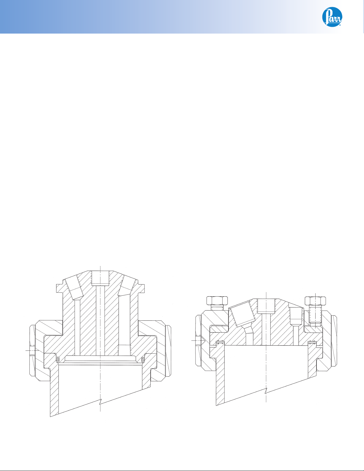
Parr Series 4560 Mini Reactors are furnished with two structural options in addition to the size, pressure
range, stirrer motor, controller and similar options. These are:
Fixed Head or Removable Head
Vessel Design
In the fi xed head design, the head of the vessel
may remain fi xed in the reactor support stand. All
attachments to the head, gas and liquid feed and
discharge lines, cooling water, vapor take-off and
condenser, thermocouple, and any electrical leads
can remain permanently in place. The reactor is
opened by removing the cover clamp sections and
lowering the cylinder away from the head.
In the removable vessel design, the entire vessel
must be removed from the support stand for charging, product recovery, and cleaning.
There is no difference in the pressure or temperature limits or basic operating instructions based
upon the fi xed head or movable vessel options.
There are differences in the design of the stand
components which adapt the vessels to the support
system.
Flat PTFE Gasket or Self Sealing
O-ring Closure
The fl at gasket is held in a recess in the vessel head
and a machine pilot on the cylinder closes the recess to completely contain the gasket. The split ring
closure used with this gasket has six cap screws
which must be tightened to develop the loading on
the gasket.
The self sealing design features an O-ring retained
in a groove on the vessel head. This design is self
sealing and the split ring used with this sealing system does not require nor have the cap screws used
with the fl at gasket.
Maximum temperatures of a given system are dependant upon the material of construction and type
of seal. Other accessories may limit operating temperature. The fl at PTFE gasket can be used to operat-
ing temperatures as high as 350 °C. The fl at fl exible
graphite gasket can be used to operating temperatures as high as 500 °C. The maximum temperature
of the vessels equipped with O-ring seals depends
upon the material used for the O-ring. The most
common material is a fl uoroelastomer (FKM) which
has a 225 °C maximum operating temperature limit.
Fixed Head with O-ring
6
Parr Instrument Company
Moveable Head with Flat Gasket
Page 7
Mini Bench Top Reactors
Installation
Pressure and Temperature Limits
The working pressure and temperature at which any
reactor or pressure vessel can be used will depend
upon the design of the vessel and the materials
used in its construction. Since all materials lose
strength at elevated temperatures, any pressure
rating must be stated in terms of the temperature at
which it applies. The standard material of construction for Parr Instrument Company is Type 316 Stainless Steel.
Limits for vessels made of other materials and for
other operating temperatures can be obtained from
Parr Customer Service. No attempt should be made
to increase these limits by making alterations or by
substituting components that are not recommended
by the Parr Instrument Company. It must also be
understood that lower pressure and temperature
limits may be required for modifi ed reactors and for
vessels made of special alloys.
Limits for vessels will be determined by the physical characteristics of the vessel material and will be
prescribed on an individual basis.
The maximum working pressure and temperature
for any vessel is governed by the design of the
vessel and the strength of the material from which
it is constructed. There is also a close relationship
between working pressure and temperature since
the strength of any material will normally fall off
as the temperature is increased. Temperature and
pressure limits are also affected by the physical
properties and temperature limits of the gaskets and
seals used in the vessel, and by any valves, gages or
other fi ttings attached to the vessel. The safe operating pressure of any system can be no higher than
that of its lowest rated component.
Working temperatures up to 225 °C are permissible
in Mini Reactors equipped with fl uoroelastomer
(FKM) O-ring seals. The higher the operating temperature above 200 °C, the shorter the life of the Oring will be. Perfl uoroelastomer (FFKM) O-ring seals
have a broad chemical resistance and can be used
to temperatures up to 300 °C. Unfortunately they
are very expensive and will generally be reserved
for unique applications. Ethylene-propylene (EP)
O-rings can be used to 170 °C and are recommend-
ed for applications such as ethers, ammonia and
amines which will rapidly destroy fl uoroelastomer
O-rings.
Pressure Vessel and Temperature Limits
In the standard pressure and temperature setup, the
system must not exceed the following:
Vessel
Material
T316SS 3000 psig (200 bar)
T316SS 3000 psig (200 bar)
T316SS 3000 psig (200 bar)
Maximum
Pressure
Maximum
Temperature
350 °C PTFE
Flat Gasket
225 °C FKM
O-Ring
300 °C FFKM
O-Ring
In the high pressure/high temperature setup, the
system must not exceed the following:
Vessel
Material
T316SS (HT) 2000 psig (138 bar) 500 °C Flexible
Maximum
Pressure
Maximum
Temperature
Graphite Flat
Gasket
All Parr reactors show the maximum safe operating
pressure and temperature imprinted on the cylinder.
An accompanied restricted operating limit tag and/
or supplemental manual is given when a component of the system limits the operation below the
imprinted valves.
www.parrinst.com
7
Page 8
Mini Bench Top Reactors
Assemble the Reactor
These reactors require at least 10 sq. ft. of workspace in a well-ventilated area with convenient
access to an electric outlet, running water, air and a
drain.
1. Set the stand in the workspace.
Bolt the stand to the bench top using the
holes in the base plate.
2. The support and heater are shipped fully assembled. The heater raises and lowers on its
support rod to permit the vessel or cylinder to
be removed. Lower the heater, open the hinged
retainer on the front of the support and slide the
vessel into its support. Fixed head vessels have
a square lip which fi ts into a matching groove in
the support plate. Removable vessels are supported by the split rings which rest on the support plate adapter. The stirrer drive connector
lifts by rotating and lifting the knob above the
belt guard. The universal joint contains a cross
pin that slips into the groove on top of the magnetic drive. There is a bracket at the back of the
area where the split ring rests. The thumb screw
on the drop band which encircles the split ring
closure should fi t into the slot on this bracket.
This will keep the vessel from rotating when
stirring viscous reactions. It may be necessary
to reposition the drop band if the gage does not
face forward when the thumb screw is in the
slot.
3. Set the Temperature Controller near the reactor,
leaving a space of at least six inches between
the controller and the base of the reactor so
that the controller will not be unduly affected by
radiant heat. Connect the reactor to the controller using information contained in its Instruction
Manual 548M or follow the steps below.
Parr Heating Only:
The Parr Heating output connector is to be used
only with Parr Instrument Company heater assemblies supplied with the appropriate heater
power cord.
Note: Do not make connections to a Variac,
Powerstat or the like to attempt to control the
heating output. The heavy inductive load on
the primary side of such devices can destroy
the internal sold state relay located in the 4848
controller.
Motor:
Secure the clamp on motor cord to the
controller with the provided screw next
to the motor socket for safety purposes.
The Motor output connector is to be used only with
Parr Instrument Company motor assemblies supplied with the appropriate motor power cord.
4. Connect the heater cord from the heater into
the heater socket on the rear panel of the Series
4848 Reactor Controller.
5. Plug the motor cord into the motor socket on the
rear of the controller.
Secure the clamp on the motor cord with
the provided screw next to the motor
socket for safety purposes.
6. Connect the thermocouple and extension wire
to both the thermocouple and to the controller
in the “Primary Temp Input” position on the rear
panel. Insert the thermocouple in the thermowell.
Labeled connections are provided on the rear
panel of the controller.
Parr Cooling Only:
The Parr Cooling output connector is to be used
only with Parr Instrument Company cooling solenoid valve assemblies supplied with the appropriate cooling power cord.
8
Parr Instrument Company
7. Connect leads from accessory packages such as
tachometer, pressure transducer and high temp
cut-off to the designated positions on the back
panel of the 4848 Controller.
8. Connect cooling water to the magnetic drive.
See Instruction Manual No. 234M.
9. Connect tubing to the rupture disc outlet and run
to a safely vented area. See Instruction Manual
231M.
Page 9
Mini Bench Top Reactors
10. Note the voltage and amperage requirement
stamped on the controller data plate, and then
plug the power cord into an appropriate outlet.
Power for these reactors should be drawn from
a grounded outlet capable of carrying up to the
full current rating of the reactor.
11. If an electric stirrer motor is supplied, turn the
speed control knob fully counterclockwise on
the Reactor Controller, turn on the motor switch
and slightly increase the speed for a short run
to check the stirrer drive system but do not turn
on the heater, put heater toggle switch in center
position (OFF). There must always be a vessel in
the heater when it is turned on, and the vessel
and heater sizes must match. If the heater is operated without proper size vessel in contact with
the heater, the heater may overheat and fail.
Identify the Valves
Gas Inlet Valve
The gas inlet valve is easily identifi ed when the
vessel is open by noting that it is connected to a dip
tube which extends to a point near the bottom of
the cylinder. With this arrangement, incoming gas is
always introduced below the surface of the liquid.
This valve includes a coupling with an “A” socket
connection for attachment of the pressure hose.
Gas Release Valve
The gas release valve is typically connected to a side
opening on the gage adapter. Gas released from
this valve will be drawn from the top of the reactor.
Liquid Sampling Valve
The liquid sampling valve is attached to the same
fi tting as the gas inlet valve and connected to the
same dip tube. This provides the operator with a
means for clearing the dip tube to be sure that any
sample taken during a run will be representative of
the charge. This can be done by opening the upper
gas inlet valve momentarily to allow the inlet gas to
force any liquid in the dip tube back into the reactor before withdrawing a sample from the sampling
valve.
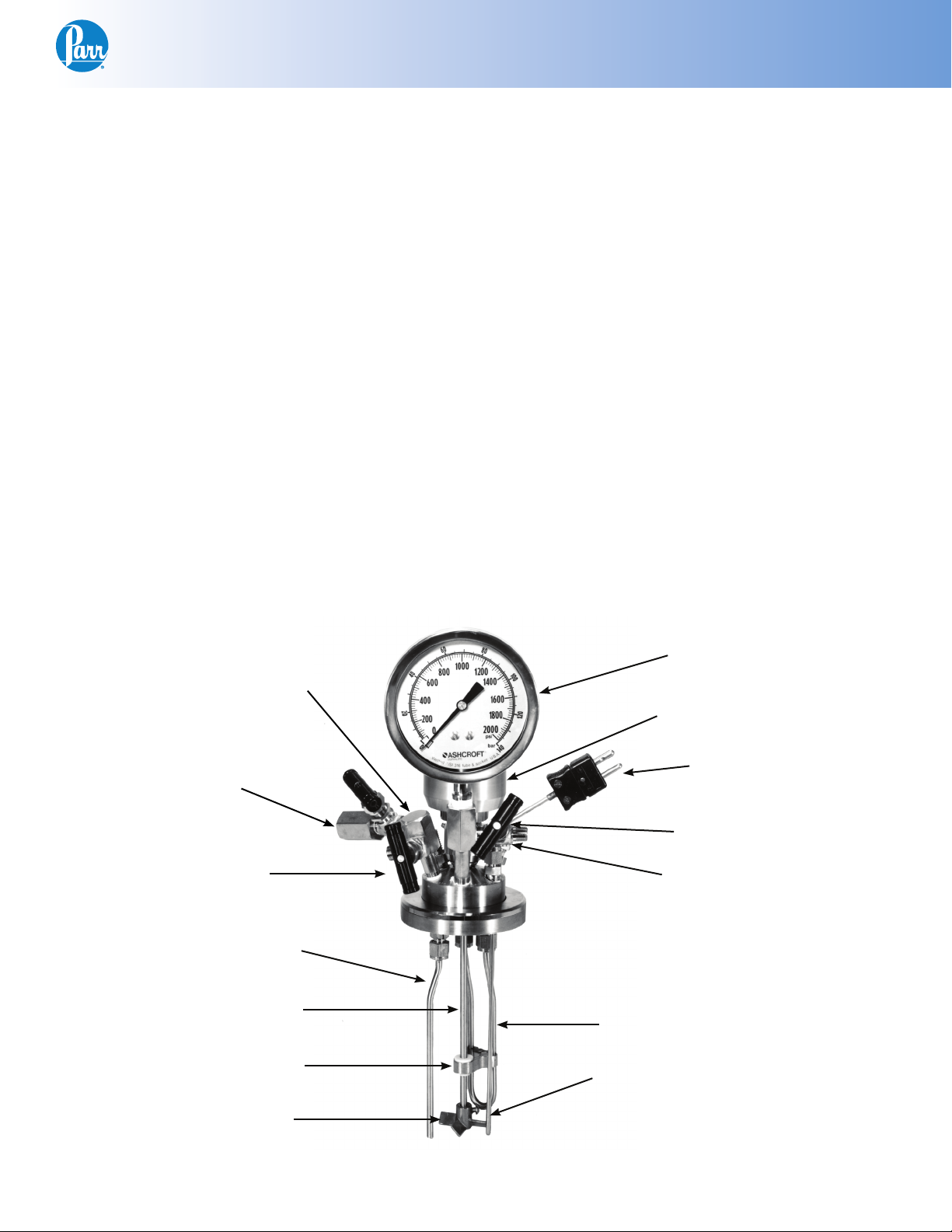
Safety Rupture Disc
Gas Inlet Valve
Liquid Sampling Valve
Dip Tube
Stirring Shaft
Lower Guide
Bearing
Pressure Gage
Magnetic Drive
Thermocouple
Gas Release Valve
Vessel Water Cooling
Channel
Cooling Loop
Thermocouple / Thermowell
Adjustable
Impeller(s)
Removable Head Shown (Standard Temperature, T316)
www.parrinst.com
9
Page 10

Mini Bench Top Reactors
Other Vessel Head Fittings
Safety Rupture Disc
There is a safety rupture disc attached to the head
which is intended to rupture and release the pressure before it reaches a dangerous level. A metal
tag wired to the safety head identifi es the burst
pressure at room temperature for that particular
disc. A similar tag is furnished with each replacement disc. This tag must remain with the apparatus
at all times so that both present and future operators will be aware of the disc rating. Users should
read the discussion of rupture discs given in the
Operating Instruction No. 231M for a complete
description of the characteristics of rupture discs
and the precautions to be observed when operating
pressure equipment protected by this type of safety
device.
A typical pre-bulged disc can be used to 90% of the
rating on the tag. For additional protection, the
user should install an adequate and safe venting
system for removing any toxic, fl ammable or volatile materials which would be released if the rupture
disc should burst. A connector for attaching 3/8” OD
tubing to the discharge port of the rupture disc is
provided for this purpose.
Heaters
The Mini Reactor Systems offer an array of heating
choices to suit the needs of the operator.
The 100 and 160 mL models are offered with a high
watt density band heater, which is to be clamped
directly onto the cylinder. After the vessel has been
placed in its holder, slide the heater onto the cylinder and tighten the clamping screw which projects
from the aluminum housing.
The 300, 450 and 600 mL Mini Reactors are standard
equipped with heating mantles housed in sturdy
aluminum shells. These mantles are made in three
sizes, designed to provide uniform heat distribution
to the walls and bottoms of these vessels. They are
attached to the support rod with a clamp, arranged
so that they can be raised or lowered on the rod as
desired.
Alternately the 300, 450 and 600 mL Reactor systems can be heated with an aluminum block heater
which features integrated cooling.
The high temperature Mini Reactor systems utilize a
higher wattage ceramic fi ber heater.
Type J Thermocouple
A Type J Thermocouple in a 1/8” diameter stainless
steel sheath is installed in each reactor. In reactors made of alloys other than stainless steel, the
stainless thermocouple is installed in a thermowell
made of the same alloy as the vessel. Connect the
thermocouple to the socket on the rear panel of the
temperature controller using the A470E2 extension
wire furnished with the reactor.
Pressure Gage
The pressure gage furnished with this reactor has
a T316 stainless steel Bourdon tube. Gages are
furnished in a variety of ranges to meet individual
needs. Typically, the gage and the rupture disc are
furnished as matched ranges. For applications
where a gage is selected with a range under 1000
psi, a relief valve is added and set to protect the
gage. A 1000 psi rupture disc is installed as the failsafe vessel protection.
For highly corrosive applications where the vapor
phase might corrode the stainless Bourdon tube,
Parr offers isolator assemblies in a variety of materials. These isolators with their internal piston isolate
the vapors from the gage.
Parr heaters are offered with optional thermowell
port to accommodate the Parr A511E bayonet style
thermocouple, an open bottom to accommodate a
cylinder bottom drain valve, and/or the quick con-
nect mounting style for conveniently changing
heater size. Please consult the experienced customer service staff at Parr Instrument Company for
assistance in determining the correct heater for your
reactor system.
Each heater must always be used with a vessel
of the size for which it was designed, and it must
always be fully attached to the vessel before heat is
turned on. Similarly, a short vessel must never be
heated in a deep heater. Without full contact with a
metal wall, a heater may overheat and burn out.
10
Parr Instrument Company
Page 11

Mini Bench Top Reactors
How to Use the Vessel
Removable Vessels
Always remove removable vessels from the support
stand before attempting to open or close them.
To open the Vessel
Open the gas release valve to discharge any internal
pressure. For the bolted closure, loosen the six cap
screws in the split ring sections. Loosen the cone
pointed screw in the outer band and lower the band
to rest on the table. The ring sections can now be
removed, and the head with all attached fi ttings is
free to be lifted from the cylinder. Handle the head
carefully so as not to damage the stirring shaft and
other internals when they are outside of the cylinder.
Before Closing the Vessel
Examine the head gasket or o-ring carefully to be
sure that it is in good condition. After considerable
use, some of the PTFE gasket may extrude into a
thin, ragged edge around the inside and outside
diameters. This does not necessarily mean that the
gasket must be replaced, but the extruded portion
should be removed with a sharp knife. Examine the
mating surfaces on the cylinder and head to be sure
they are clean and free from burrs; then set the head
on the cylinder.
Sealing Vessels with PTFE Gaskets
Initially tighten the cap screws to 15 ft-lbs then
increase to 20-25 ft-lbs. Tightening should proceed
in a criss-cross pattern rather than progressively
around the circle. Let the vessel stand for about fi ve
minutes after the initial tightening; then tighten the
cap screws again. This will compensate for any ten-
dency of the PTFE gasket to fl ow under the loading
pressure.
Sealing with Flexible Graphite Gaskets
Initially tighten the cap screws to 15 ft-lbs then increase to 20-25 ft-lbs. Tightening should proceed in a
criss-cross pattern rather than progressively around
the circle.
Flexible graphite gaskets tend to be somewhat
fl akey. To extend the useful life of these gaskets, fi rst
rough up the sealing surface of the cylinder with
120 grit sand paper to ensure the gasket remains in
the head groove and does not stick to the cylinder.
Secondly, coat both sealing surfaces with a silicone
lubricant. This process will aid in compressing the
gasket so it does not break apart after one use.
Recommended Bolt Torque
PTFE or
Flexible Graphite
O-ring Closures
The split rings used with an o-ring seal do not include any compression bolts.
With the easy close split ring, the o-ring is attached
to the pilot on the underside of the head. When
closing the vessel, set the head on the cylinder and
press down on the head until the bottom of the head
meets with the cylinder fl ange. Then install the two
split ring halves and attach the outer drop band.
Note: The following steps are common to both
head confi gurations.
0-3000 psig
(0-200 bar)
20-25 ft-lbs
Fixed Head Vessels
Fixed head vessels are opened and closed with the
same procedure used for removable vessels except
that they are opened and closed with the head in
place. Before opening the vessel lower the heater
and swing it well to the side so that it will not be
damaged by any materials that drip from the ves-
sel as it is opened. When closing the vessel always
hold the cylinder until both split ring sections are in
place to lock the cylinder to the head.
Gas Connections
For a gas connection to the vessel, use the A495HC
pressure hose furnished with the reactor. Attach the
hose to a pressure regulator or fl ow control valve on
a commercial gas cylinder using PTFE tape or other
thread sealant on the 1/8” NPT male nipple and on
the 1/4” NPT bushing, if used. Then screw the Type
A coned pressure fi tting into the adapter attached
to the gas inlet valve and tighten the compression nut fi rmly. Do not use any thread dope or tape
on the coned fi tting. The A495HC pressure hose is
made of reinforced Nylon which can be used for all
non-corrosive gases at pressures up to 2500 psig.
For operations involving corrosive gases, this hose
should be replaced with an A490HC hose (optional)
which has a PTFE lining and a braided stainless steel
outer covering. These hoses have the same fi ttings
as in the A495HC.
www.parrinst.com
11
Page 12

Mini Bench Top Reactors
Pressurizing the Vessel
Check all valves carefully before admitting gas into
the system. The liquid sampling valve must remain
closed throughout the charging procedure. The gas
release valve must also be closed unless the vessel
is to be purged, or unless there is to be a continuous
fl ow through the reactor during a run. Always make
certain that the pressure in the gas tank is greater
than the pressure in the vessel; otherwise liquid
will be forced out of the vessel and into the gas
tank when the inlet valve is opened. If there is any
possibility that the tank pressure might not be high
enough to force gas into the reactor, install a one
way check valve (optional) in the gas line to prevent
any reverse fl ow.
With the inlet valve open and the fl ow control valve
on the gas tank closed, open the main valve on the
gas tank only about one-quarter turn; then use the
fl ow control valve or the valve on a pressure regulator to control the fl ow of gas into the vessel. After
the desired pressure has been reached, close the
tank valves and the vessel inlet valve and disconnect the hose at the vessel end.
Do Not Overfi ll the Vessel
Always watch the pressure gage closely when admitting gas so as not to exceed the maximum working limit. Remember that any subsequent increase
in temperature will raise the pressure. Also, be
sure that the amount of liquid placed in the vessel
is carefully controlled. As a general rule, the liquid
charge should not exceed two-thirds of the capacity of the cylinder. Too much liquid in the vessel can
lead to development of dangerous pressures if suffi cient space is not provided for expansion when the
liquid is heated. This hazard is explained in greater
detail in a warning statement included in the Instruc-
tion Manual No. 230M.
Releasing Pressure
Use the gas release valve to reduce the pressure in
the vessel if the reactor is accidentally overcharged
when fi lling. Use this valve also to release any
excess pressure during a run and to exhaust the
vessel at the end of a run. If the discharge gases are
fl ammable or toxic, discharge to an exhaust hood or
to any other safe release point.
Withdrawing Liquid Samples
Liquid samples may be withdrawn from the sampling valve attached to the same adapter as the gas
inlet valve whenever the vessel is pressurized. Al-
ways close the inlet valve before withdrawing a liquid sample and open the sampling valve cautiously
because liquid will be discharged with considerable
force. Be particularly careful if the temperature of
the sample is above its boiling point at atmospheric
pressure. If so, it will “fl ash” and be lost as soon
as it is released from the vessel. This problem can
be avoided by connecting an optional 4351 Sample
Collection Vessel to the sampling valve to collect the
liquid into an appropriate receiver. The addition of
a small amount of gas can be used to clear the dip
tube between liquid samples so that the next sample drawn through the tube will truly be representative of the mixture.
Initial Operating Test
Read all operating instructions carefully so as to be
well acquainted with the correct procedures for handling the vessel and for operating the controller and
other accessories. An initial operating test should
be made, with only water, to check the apparatus
before starting the fi rst experimental runs. For this
initial test, fi ll the cylinder not more than half full of
water and run the temperature up to 150 ºC while
checking the apparatus for leaks and observing the
performance of the temperature controller.
Internal Cooling Loop
Each Mini Reactor (except the 100 and 160 mL sizes)
has a single loop cooling coil installed in the vessel with compression fi ttings on the head for con-
necting 1/4” copper or plastic tubing to the loop.
(Special 1/8” OD spiral coils can be furnished for
100 mL & 160 mL if required. Due to internal space
limitations these coils are attached with male connectors on the top side of the head thereby making
the coil captive.) A slow, continuous fl ow of cold
water through a cooling loop proves a very effective means for controlling temperature overshoot
in these reactors, particularly when operating at
temperatures below 150 °C. Water fl ow through the
loop can be controlled automatically using a solenoid valve in the cold water line, and connected to
the cooling socket on the rear panel of the Tempera-
ture Controller. With this arrangement, cold water
will be admitted to the cooling loop whenever the
controller calls for cooling.
If internal cooling is not desired, the cooling loop
can be removed and the opening in the head can
be closed with No. 79HW, 1/8” NPT plugs. Optionally, other 1/8” NPT threaded fi ttings can also be
installed in the coil openings.
12
Parr Instrument Company
Page 13

Air Motor
Mini Bench Top Reactors
Variable speeds from 100 to 2000 rpm with no spark
hazard can be obtained by replacing the standard
motor with an A1393HC air motor assembly. This
motor operates on compressed air which must be
supplied at 40 psig minimum pressure with at least
10 CFM available at that pressure. It is furnished
with a speed control valve and oiler, all assembled
on a mounting bracket.
To operate reactors equipped with an air motor,
mount the assembly fi rmly on the stand and con-
nect the air hose to a compressed air line. For best
torque and speed control the piping to the motor
should be at least 1/4" IPS or larger. Fill the oiler
with SAE 10 oil and adjust the oiler to feed one drop
per minute into the air stream. For long continu-
ous runs at high speeds the oiling rate should be
increased to three drops per minute.
Air Motor Option
If the motor becomes sluggish, fl ush it with a nonfl ammable solvent in a well ventilated area. Disconnect the air line and muffl er and pour a small
amount of solvent into the inlet port. Rotate the
shaft by hand in both directions for a few minutes;
then connect the air line and run the motor until
there is no further trace of solvent in the exhaust.
If the muffl er felts are dirty, wash them in solvent or
replace them.
Re-lubricate the motor with a squirt of oil into the
chamber and reassemble.
If it becomes necessary to disassemble the motor to
replace the vanes, follow the directions given in the
instruction sheet published by the Gast Manufactur-
ing Corporation, Benton Harbor, Michigan.
www.parrinst.com
13
Page 14

Mini Bench Top Reactors
Explosion Proof Operation
If the local safety code requires that equipment installed in the user’s laboratory must be explosion proof
there are four possible ignition hazards to be considered:
1. The Motor
The standard variable speed motor is not explosion proof, yet these motors are not unduly hazardous if operated in a well ventilated location
where care is taken to prevent the accumulation
of explosive gases or vapors. To eliminate any
possible spark hazard originating at the motor, Parr can furnish an air motor as described
previously, or the reactor can be equipped with
a variable speed, explosion proof motor which
is approved for use in Class 1, Div. 1, Groups C
& D, and Class 2, Groups E, F, & G atmospheres.
Explosion proof motors are furnished with a
temporary power cord and plug which are not
explosion proof. The user should remove this
temporary wiring and replace it with an explosion proof switch and wiring which will comply
with the local electrical code.
2. The Temperature Controller
The Temperature Controllers furnished with
these reactors contain switches and other elements which are not explosion proof. The minimal spark hazard associated with these units
can be resolved by installing the controller in a
remote location outside of the hazardous area or
by enclosing it in an approved explosion proof
housing. If enclosed within a positive pressure,
clean air housing, the discharge from the housing must be directed into a safe area. If requested, Parr will furnish the long lead wires needed
to mount the controller in a remote location. If
the controller is to be installed in an explosion
proof housing, the user must provide the necessary housing and installation.
3. The Heater
The elements in the heater could be dangerous
in an explosive atmosphere if the surface temperature of the element becomes high enough
to ignite fl ammable vapors. This hazard must be
evaluated for each individual installation since
major modifi cations are required if the heater
must be isolated from the surrounding atmosphere. Users who consider this a signifi cant
hazard are urged to contact the Parr Instrument
Company for further discussion and suggestions
which might be helpful. Parr is currently offering
aluminum block heaters and circulating jacketed
cylinders which can be used in hazardous environments.
4. The Wiring
Unless specifi cally designed for use in hazardous atmospheres, the wiring in these reactors
will not meet the standards prescribed for explo-
sion proof equipment. Optional intrinsically safe
barriers are also available.
14
Parr Instrument Company
Page 15

Mini Bench Top Reactors
Periodic Pressure Tests
Each cylinder used in a Parr stirred reactor is tested
under hydrostatic pressure to 1.3 times its maximum rating before it is released from the factory.
Micrometer caliper measurements are taken during this test to check the defl ection of the walls of
the cylinder under pressure. Excessive defl ection
or failure of the metal to resume its original dimensions after pressure is released indicates that a
cylinder is potentially unsafe and it will be rejected.
Similar tests should be made at regular intervals
during the life of each cylinder, and particularly
whenever the user suspects that the equipment has
been over-stressed or damaged.
Some laboratories maintain hydraulic test facilities
and make it a rule that all pressure vessels must
be tested at regular intervals. Records are kept of
defl ections at specifi c test pressures so that any
increase in defl ection becomes a warning that the
metal has lost strength. Any cylinder which fails to
return to its original dimensions after application of
the prescribed hydrostatic test should be discarded
as unsafe for further use.
Users who do not have pressure test facilities can
return any Parr pressure vessel to the factory for hydrostatic testing and overhaul. This should be done
whenever the metal shows excessive damage from
corrosion or whenever an over-pressure or other
unusual occurrence raises any safety questions. To
return a vessel for repair contact Parr Instrument
Company for a return authorization number. Apparatus returned for testing and overhaul should be
shipped prepaid to the Parr Instrument Company,
211-53rd Street, Moline, Illinois 61265. An order or
letter of instructions should be mailed to the same
address, as no repair work will be started without
specifi c instructions and a Health & Safety Assurance Certifi cation form (F0042) signed by a respon-
sible user.
Accessories
Liners
Glass or PTFE liners can be furnished to fi t most
Parr reactors. These liners slide into the cylinder.
Although they will not keep corrosive vapors from
reaching the surfaces of the cylinder and head, they
make it much easier to add and remove liquid reactants, and they give some protection to the cylinder
when working with corrosive solutions. It must be
noted, however, that adding a PTFE liner will slow
the heat transfer rate into the vessel, and it may be
necessary to adjust the temperature control method
to prevent overheating.
Liner Part Numbers
Fits ID
2.06” 100 mL 762HC7 762HC7HA
2.5” 160 mL 762HC8 762HC8HA
2.5” 300 mL 762HC 762HC4HA
2.5” 450 mL 762HC2 762HC5HA
2.5” 600 mL 762HC3 762HC6HA
Cylinder
Size
Spare Parts Kit
Spare parts kits are available for these reactors. The
kits will provide a reserve supply of parts and tools
suffi cient to handle most normal replacements and
emergency repairs during a year of heavy usage.
The kits contain small perishable items required for
continuous operation including gaskets, bushings,
rupture discs and seals. They can be ordered from
any Parr Dealer or direct from the Parr Instrument
Company. The order must specify the reactor size
and indicate type of rupture disc, stirrer drive and
whether it has a fl at-gasket or O-ring closure. It is
most advantageous to provide the complete vessel
number from the head or cylinder.
Glass
Liner
PTFE
Liner
www.parrinst.com
15
Page 16

Mini Bench Top Reactors
General Maintenance Notes
1. Periodically inspect all electrical wiring and pressure connections for excessive corrosion. Suspect parts should be replaced by components
only supplied by Parr Instrument Company.
2. Always use appropriate wrenches on all fi ttings
and valves. Never use pliers or pipe wrenches.
3. Head and cylinder service fi xtures are available
for convenience and protection of components
during maintenance of your reactor.
4. A light coating of thread lubricant, such as Parr
High Temperature Anti-Seize Lubricant (424HC2),
applied to the straight threads and to the nose
of coned adapter will help to obtain a tight joint.
PTFE tape should be used only on all tapered
(NPT) threads not NPS straight threads.
5. NPT (National Pipe Taper) threads should not be
disassembled any more than necessary. It will
become increasingly diffi cult to maintain a tight
seal with these tapered threads if the joint is
made and broken repeatedly.
9. Routinely inspect cap screws on split ring closure for lubrication and cleanliness. It is important to clean and lubricate periodically so that
the required torque is achieved when tightening
the bolts.
10. To operate reactors equipped with an air motor,
connect air hose to a compressed air line. For
best torque and speed control the piping to the
motor should be at least 1/4” IPS or larger. Fill
the oiler with SAE 10 oil and adjust the oiler feed
to one drop per minute into the air stream. For
long continuous runs at high speeds the oiling rate should be increased to three drops per
minute. If the motor becomes sluggish, fl ush
it with a non-fl ammable solvent in a well ventilated area. Disconnect the air line and muffl er
and pour a small amount of solvent into the inlet
port. Rotate the shaft by hand in both directions
for a few minutes; then connect the air line and
run the motor until there is no further trace of
solvent in the exhaust. If the muffl er is dirty,
replace it. Re-lubricate the motor with a squirt of
oil into the chamber and reassemble.
6. Do not use oil or anti-seize lubricant on threads
or fi ttings if the vessel is to be used with oxygen.
7. If your vessel is equipped with a loose compression ring be sure that it is in place on the head
before attaching any head fi ttings. The compression ring cannot be installed after fi ttings have
been screwed into the head.
8. Clean all threads and gas passages thoroughly
and remove all tape fragments when overhauling a vessel. An ultrasonic bath is excellent for
cleaning metal parts, but do not place a thermocouple probe, pressure gage, face seals or ball
bearings in an ultrasonic bath. Periodic cleaning
may be performed on the exterior surfaces of
the reactor stand with a lightly dampened cloth
containing a mild soap solution. All electrical
power should be disconnected when cleaning.
11. If servicing assistance is needed, contact Parr
Instrument Company directly at the address
shown on the back of these instructions.
16
Parr Instrument Company
Page 17

4560 Series Reaction Vessel Parts List
Standard Vessel Fittings
(3000 psig/ 350°C)
Vessel Closure and Standard Internal Parts
SAFETY HEAD ASSY
A1120HC6
593HC
SERIES
GAGE
MAG DRIVE ASSY
COUPLING
CONNECTOR
A888HC2
(BELOW 366VB)
366VB
288VB
A92HWAD
CONNECTOR
Mini Bench Top Reactors
A472E THERMOCOUPLE
W/ A833HC CONNECTOR
818HC
HEAD
457HC2 GASKET REF
832HC
DIP TUBE
822HC15
SHAFT
A834HC
MALE CONNECTOR
TYP (3) PLACES
831HC
COOLING LOOP
A837HC
PROPELLER
Consult the itemized list for your reactor, provided
along with this manual. For purpose of reactor iden-
tifi cation the following abbreviation codes are used:
RV - Removable Vessel FH - Fixed Head
FG - Flat Gasket Seal OR - O-ring Seal
SS - T316 only SP - Special Alloy
MD - Magnetic Drive
FMD - Footless Magnetic Drive
* For parts made from alternate materials use the
codes shown below as a suffi x to the standard part
number.
CM - Alloy 400 CC - Alloy 20Cb3
CT - Alloy 600 CA - Titanium G2 or G4
CG - Alloy b-2 CH - Alloy C-276
CX - Zirconium
A122VB
STRAIGHT
VALVE
420HC
ADAPTER
835HC
ADAPTER TEE
A146VB
ANGLE VALVE
(GAGE HIDDEN FOR CLARITY)
GAGE ADAPTER
Cylinders*
Part No. Description Code
452HC8 Cylinder, 100 mL FG
2342HC4 Cylinder, 100 mL OR
452HC9 Cylinder, 160 mL FG
2342HC5 Cylinder, 160 mL OR
452HC Cylinder, 300 mL FG
2342HC Cylinder, 300 mL OR
452HC2 Cylinder, 450 mL FG
2342HC2 Cylinder, 450 mL OR
452HC3 Cylinder, 600 mL FG
2342HC3 Cylinder, 600 mL OR
* For Special Fittings
836HC
A455HC SPLIT
RING ASSY W/
A456HC DROP
BAND
REF
A122VB
STRAIGHT
VALVE
www.parrinst.com
17
Page 18

Mini Bench Top Reactors
Magnetic Stirrer
Part No. Description
A1120HC6 Magnetic Stirrer, 16in-lb
A2140HC2 Footless Magnetic Stirrer, 16 in-lb
A2685HC Cooling Sleeve
827HC O-ring
2714HC Hose connector
See manual 234M for a full list of magnetic stirrers
and parts.
Heads for A1120HC6 Magnetic Stirrer*
Part No. Description Code
818HC Head, for thermocouple RV FG
818HC2* Head, for thermowell RV FG
2201HC Head, for thermocouple FH FG
2201HC2* Head, for thermowell FH FG
2340HC Head, for thermocouple RV OR
2340HC* Head, for thermowell RV OR
2343HC Head, for thermocouple FH OR
2343HC2* Head, for thermowell FH OR
Heads for A2140HC2 Footless Magnetic Stirrer*
Part No. Description Code
818HC39 Head, for thermocouple RV FG
818HC40* Head, for thermowell RV FG
2201HC5 Head, for thermocouple FH FG
2201HC6* Head, for thermowell FH FG
2340HC5 Head, for thermocouple RV OR
2340HC6* Head, for thermowell RV OR
2343HC5 Head, for thermocouple FH OR
2343HC6* Head, for thermowell FH OR
Gaskets & Seals
Part No. Description Code
457HC2 Head Gasket, PTFE FG
457HC3KL Head Gasket, Flexible
Graphite
2341HCJV O-ring FKM OR
2341HCJK O-ring FFKM OR
48HC Gasket, silver; A1120HC
48HCFG Gasket, gold plated; A1120HC
2142HC Gasket, silver; A2140HC
2142HCFG Gasket, gold plated; A2140HC
2142HC2KL Gasket, graphite; A2140HC
FG
Split Rings and Accessories
Part No. Description Code
A455HC Split Ring Assembly w/ bolts RV FG
454HC Compression Ring, Head Drop
Band
A456HC Drop Band w/ screw RV FG
A2205HC S/R, 6 bolt, Captive Compres-
sion Ring
232HCFDE Compression bolt, GR-B7 FG
2195HC Split ring, quick close OR
372HC2 Wrench, 9/16”
RV FG
FH FG
Dip Tubes
Part No. Description Code
832HC Dip Tube for 300 mL SS
832HC4* Dip Tube with nut, 300 mL SP
832HC2 Dip Tube, 450 mL SS
832HC5* Dip Tube with nut, 450 mL SP
832HC3 Dip Tube, 600 mL SS
832HC6* Dip Tube with nut, 600 mL SP
832HC8* Dip Tube with nut, 160 mL SS / SP
832HC19* Dip Tube with nut, 100 mL SS / SP
Male Connectors
Part No. Description Code
A833HC Male Connector, 1/8NPTM x 1/8T,
(Thermocouple)
A834HC Male Connector, 1/8NPTM x
3/16T, (SS dip tube)
A92HW* Male Connector, 1/8NPTM x 1/4T,
(Special mate diptube)
A138CA Male Connector, 1/8NPTM x 1/4T,
TW, (thermowell)
SS
SS
SS / SP
SP
Cooling Loop
Part No. Description Code
831HC Cooling Loop for 300 mL SS
831HC6* Cooling Loop for 300 mL SP
831HC2 Cooling Loop for 450 mL SS
831HC7* Cooling Loop for 450 mL SP
831HC3 Cooling Loop for 600 mL SS
831HC8* Cooling Loop for 600 mL SP
A92HW* Internal Connector, cooling loop*
217VB* Nut for A92HW* ¼” T
218VB* Ferrule for A92HW* ¼” T
* For Special Fittings
18
Parr Instrument Company
Page 19

Mini Bench Top Reactors
Stirrer Support Bracket
Part No. Description Code
A1260HC Stirrer Bracket w/ bushing SS
A1260HC2* Stirrer Bracket w/ bushing SP
1261HC Stirrer Bracket Bushing, PTFE
graphite
1261HC2KF Stirrer Bracket Bushing, graphite
Note: 450 mL and 600 mL only
Stirrer Shafts for A1120HC6 Magnetic Stirrer*
Part No. Description Code
822HC15 Shaft, 300 mL, 5.81” RV MD
822HC30 Shaft, 300 mL, 6.42” FH MD
822HC16 Shaft, 450 mL, 7.81” RV MD
822HC31 Shaft, 450 mL, 8.92” FH MD
822HC17 Shaft, 600 mL, 9.81” RV MD
822HC32 Shaft, 600 mL, 10.92” FH MD
822HC18 Shaft, 100 mL, 3.88” RV MD
822HC33 Shaft, 100 mL, 4.99” FH MD
822HC18 Shaft, 160 mL, 3.88” RV MD
822HC33 Shaft, 160 mL, 4.99” FH MD
Gage Assembly
Part No. Description
836HC Gage adapter, 1/4” NPT(F) top x 1/8”
NPT(F) side port
836HC6 Gage adapter, 1/4” NPT(F) top x 1/8”
NPT(F) + two 1/4” NPT(F) side ports
836HC7 Gage adapter, 1/4” NPT(F) top, one 1/8” +
1/4” NPT(F) side ports
A122VB Needle Valve T316 1/8 NPTM
Gages
Part No. Description
593HCP1AD Pressure Gage, 3-1/2”, 100 psi/bar
593HCP2AD Pressure Gage, 3-1/2”, 200 psi/bar
593HCP6AD Pressure Gage, 3-1/2”, 600 psi/bar
593HCPD Pressure Gage, 3-1/2”, 1000 psi/bar
593HCPF Pressure Gage, 3-1/2”, 2000 psi/bar
593HCPG Pressure Gage, 3-1/2”, 3000 psi/bar
Heaters
Part No. Description
A2230HCEB Heater, 300 mL, 115V
A2230HCEE Heater, 300 mL, 230V
Stirrer Shafts for A2140HC2 Footless Magnetic Stirrer
Part No. Description Code
2141HC Shaft, 300 mL, 7.93” RV FMD
2141HC7 Shaft, 300 mL, 9.05” FH FMD
2141HC2 Shaft, 450 mL, 9.93” RV FMD
2141HC8 Shaft, 450 mL, 11.05” FH FMD
2141HC3 Shaft, 600 mL, 11.93” RV FMD
2141HC9 Shaft, 600 mL, 13.05” FH FMD
2141HC46 Shaft, 100/160 mL, 5.93” RV FMD
2141HC50 Shaft, 100/160 mL, 7.05” FH FMD
Impellers*
Part No. Description Code
A2148HC Impeller with screw, for 2141HC
series shafts
A837HC Impeller with screw, for 822HC
series shafts
FMD
MD
A2230HC2EB Heater, 450 mL, 115V
A2230HC2EE Heater, 450 mL, 230V
A2230HC3EB Heater, 600 mL, 115V
A2230HC3EE Heater, 600 mL, 230V
A2235HCEB Heater, 100/160 mL, 115V
A2235HCEE Heater, 100/160 mL, 230V
* For Special Fittings
www.parrinst.com
19
Page 20

Mini Bench Top Reactors
Thermocouple/Thermowell
Part No. Description Code
A833HC Male Conn, 1/8” NPT(M) ×
1/8” T for Thermocouple
A138CA Male Conn, 1/8” NPT(M) ×
1/4” T for thermowell
A1453HC Thermowell, 1/4”OD
A472E Thermocouple, Grounded
300mL Type J, 7-1/2
A472E2 Thermocouple, Grounded
450mL Type J, 9-1/2
A472E3 Thermocouple, Grounded
600mL Type J, 11-1/2
A472E4 Thermocouple, Grounded
100/160mL Type J, 5-1/2
A490E Thermocouple, Dual
Grounded, 7-1/2, 1/8”OD
A490E2 Thermocouple, Dual
Grounded 9-1/2
A490E3 Thermocouple, Dual
Grounded 11-1/2
213VBAD Nut 1/8” T TC
214VBAD Ferrule 1/8” T TC
217VBAD Nut 1/4” T TW
218VBAD Ferrule 1/4” T TW
TC
TC
TC
TC
TC
TC
TC
External Fittings
Part No. Description
A888HC2 Rupture disc assembly
49HC2 Orifice cone
527HC Orifice ring
433HC4 Safety head outlet
366VBD Hex Coupling, 1/4 NPTF
288VBAD Male Connector, 3/8” T-1/4” NPTM
A92HWAD Male Connector 1/8 NPTMx1/4T
(T316SS for top of cooling loop)
79HW* Plug, Hex Head 1/8” NPTM
835HC Adapter, two 1/8” NPT(F) side ports
A122VB Needle Valve T316 1/8 NPTM
A146VB Angle Valve T316 1/8 NPTM-M
420HC Adapter, T303 A Skt × 1/8 NPTF
Rupture Disc Assembly
See manual 231M for a full list of safety rupture disks.
Specify volume & head style (fi xed or movable)
* For Special Fittings
20
Parr Instrument Company
Page 21

Mini Bench Top Reactors
Digitally signed
by Vern Moon
Gas Entrainment Upper Shaft
Part No. Description Code
2027HC 2.83” Shaft, upper MV MD
2027HC3 3.94” Shaft, upper FH MD
Gas Entrainment Lower Shaft
Part No. Description Code
2028HC5 3.04” Shaft, 300 mL MD
2141HC1 8.16” Shaft, 300 mL FH FMD
2141HC15 7.11” Shaft, 300 mL MV FMD
4561 Gas Entrainment Assembly
300mL Removable Vessel
REF
818HC HEAD
REF
2027HC SHAFT
Part No. Description Code
2028HC6 4.04” Shaft, 450 mL MD
2141HC12 9.72” Shaft, 450 mL FH FMD
2141HC16 8.61” Shaft, 450 mL MV FMD
2028HC7 5.54” Shaft, 600 mL MD
2141HC13 11.22” Shaft, 600 mL FH FMD
2141HC17 10.11” Shaft, 600 mL MV FMD
2028HC8 1.18” Shaft, 100/160 mL MD
2141HC14 6.85” Shaft, 100/160 mL FH FMD
2141HC18 5.73” Shaft, 100/160 mL MV FMD
832HC DIP TUBEA834HC MALE CONN
REF
A1870HC2 STIRRER BRKT REF
1869HC OR 1869HC2KF
BUSHING NOT FURNISHED
SEE NOTE
452HC CYLINDER
REF
2070HC IMPELLER
A833HC MALE CONN
A472E/A490E THERMOCOUPLE
REF
REF
457HC2 GASKET
2028HC5 SHAFT
REF3.94
4563 Gas Entrainment Assembly
600mL Removable Vessel
A2043HC BAFFLE
REF
.46 REF
NOTE:
FOR 1/4" OD SPECIAL ALLOY AND HIGH
TEMP DIP TUBES USE A1870HC
www.parrinst.com
21
Page 22

Mini Bench Top Reactors
4560 Series Reaction Vessel Parts List
High Temperature Vessel Fittings
(2000 psig/500°C)
Vessel Closure and Standard Internal Parts
593HC SERIES
GAGE
A1120HC6
1446HC2
ADAPTER
35HC
40HC
MAG DRIVE ASSY
A544VBKL
280VB NIPPLE
VALVE
SAFTEY HEAD ASSY
(BELOW 302VBAD)
CONNECTOR
A888HC2
302VBAD
A92HWAD
A92HWAD
CONNECTOR
CONNECTOR
A472E
THERMOCOUPLE
W/ 3366HC, 3367HC
3460HC
HEAD
1359HC NUT
1360HC FERRULE
831HC24
COOLING LOOP
A837HC
PROPELLER
914HC
LOCKNUT
REF
1261HCKL
BUSHING
(OPTIONAL)
832HC37
DIP TUBE
822HC30
SHAFT
35HC
40HC
*Special Materials
Consult the itemized list for your reactor, provided
along with this manual. For purpose of reactor iden-
tifi cation the following abbreviation codes are used:
RV - Removable Vessel FH - Fixed Head
FG - Flat Gasket Seal SP - Special Alloy
SS - T316 only MD - Magnetic Drive
FMD - Footless Magnetic Drive
* For parts made from alternate materials use the
codes shown below as a suffi x to the standard part
number.
CM - Alloy 400 CC - Alloy 20Cb3
CT - Alloy 600 CA - Titanium G2 or G4
CG - Alloy b-2 CH - Alloy C-276
CX - Zirconium
A544VB2KL
ANGLE VALVE
1452HC6
ADAPTER TEE
1452HC5
GAGE ADAPTER
(GAGE HIDDEN FOR CLARITY)
A544VBKL
VALVE
280VB NIPPLE
Cylinders*
Part No. Description Code
452HC Cylinder, 300 mL FG
452HC2 Cylinder, 450 mL FG
452HC3 Cylinder, 600 mL FG
Heads*
Part No. Description
3619HC Head, for thermocouple RVMD
3619HC* Head, for thermowell RVMD
3460HC* Head, for thermocouple FHMD
3460HC2* Head, for thermowell FHMD
3460HC3 Head, for thermocouple FHFMD
* For Special Fittings
22
Parr Instrument Company
Page 23

Mini Bench Top Reactors
Gaskets*
Part No. Description Code
457HC3KL Head Gasket, Flexible Graphite RV FG
48HC Gasket, silver; A1120HC RV FG
48HCFG Gasket, gold plated; A1120HC FH FG
2142HC Gasket, silver; A2140HC FH FG
Closure*
Part No. Description Code
A455HC7 Split Ring Assembly with bolts RV
454HC Compression Ring, Head RV
A456HC Drop Band RV
A2205HC3 Split Ring Assembly with com-
pression ring & bolts
372HC2 Wrench, 9/16” RV
3646HC Wrench, 7/16” FH
FH
Dip Tubes*
Part No. Description Code
832HC37 Dip Tube for 300 mL
832HC38 Dip Tube, 450 mL
832HC39 Dip Tube, 600 mL
Cooling Loop*
Part No. Description Code
831HC24 Cooling Loop for 300 mL
831HC25 Cooling Loop for 450 mL
831HC26 Cooling Loop for 600 mL
1359HC* Nut, 1/4” Tube Seal
1360HC* Ferrule, 1/4” Tube Seal
Stirrer Support Bracket
Part No. Description Code
A1260HC2* Stirrer Bracket w/ bushing
1261HC2KF Stirrer Bracket Bushing
Magnetic Stirrer
Part No. Description
A1120HC6 Magnetic Stirrer, 16in-lb
A2140HC2 Footless Magnetic Stirrer, 16 in-lb
A2685HC Cooling Sleeve Assembly
827HC O-ring
2714HC Hose connector
See manual 234M for a full list of magnetic stirrers
and parts.
Stirrer Shafts for A1120HC6 Magnetic Stirrer*
Part No. Description Code
822HC15 Shaft, 300 mL, 5.81” RV MD
822HC30 Shaft, 300 mL, 6.42” FH MD
822HC16 Shaft, 450 mL, 7.81” RV MD
822HC31 Shaft, 450 mL, 8.92” FH MD
822HC17 Shaft, 600 mL, 9.81” RV MD
822HC32 Shaft, 600 mL, 10.92” FH MD
Stirrer Shafts for A2140HC2 Footless Magnetic Stirrer*
Part No. Description Code
2141HC Shaft, 300 mL, 7.93” RV FMD
2141HC7 Shaft, 300 mL, 9.05” FH FMD
2141HC2 Shaft, 450 mL, 9.93” RV FMD
2141HC8 Shaft, 450 mL, 11.05” FH FMD
2141HC3 Shaft, 600 mL, 11.93” RV FMD
2141HC9 Shaft, 600 mL, 13.05” FH FMD
Impellers*
Part No. Description Code
A2148HC Impeller with screw, for 2141HC
series shafts
A837HC Impeller with screw, for 822HC
series shafts
FMD
MD
Note: 450 mL and 600 mL only
Thermowell*
Part No. Description Code
A1453HC* Thermowell, specify reactor vol-
ume & head style when ordering
Gages
Part No. Description
593HCP1AD Pressure Gage, 3-1/2”, 100 psi/bar
593HCP2AD Pressure Gage, 3-1/2”, 200 psi/bar
593HCP6AD Pressure Gage, 3-1/2”, 600 psi/bar
593HCPD Pressure Gage, 3-1/2”, 1000 psi/bar
593HCPF Pressure Gage, 3-1/2”, 2000 psi/bar
593HCPG Pressure Gage, 3-1/2”, 3000 psi/bar
* For Special Fittings
www.parrinst.com
23
Page 24

Mini Bench Top Reactors
Thermocouple/Thermowell
Part No. Description Code
A472E Thermocouple, Grounded
300mL Type J, 7-1/2
A472E2 Thermocouple, Grounded
450mL Type J, 9-1/2
A472E3 Thermocouple, Grounded
600mL Type J, 11-1/2
A472E4 Thermocouple, Grounded
100/160mL Type J, 5-1/2
A490E Thermocouple, Dual
Grounded, 7-1/2, 1/8”OD
A490E2 Thermocouple, Dual
Grounded 9-1/2
A490E3 Thermocouple, Dual
Grounded 11-1/2
3366HC Nut, 1/8” Tube Seal TC
3367HC Ferrule, 1/8” Tube Seal TC
1360HC Ferrule SS, 1/4” Tube Seal TW
1359HC Nut, 1/4” T Seal TW
A1453HC Thermowell, 1/4” OD
TC
TC
TC
TC
TC
TC
TC
Specify volume & head style (fi xed or movable)
External Fittings
Part No. Description
A888HC2 Rupture disc assembly
49HC2 Orifice cone
527HC Orifice ring
433HC4 Safety head outlet
A544VBKL Valve, Straight 1/8” NPTF
A544VB2KL Valve, Angled 1/8” NPTF
280VBAD Nipple, 1/8” NPTM
A92HWAD Male Connector 1/8 NPTMx1/4T
(T316SS for top of cooling loop)
35HC Compression Nut
40HC Bushing
1452HC5 Gage Adapter
1452HC6 Valve Adapter
302VBAD Female Conn, 38” Tube – 1/4” NPTF
1446HC2 Adapter, ‘A’ Cone F – 1/8” NPTM
424HC2 Anti-Seize Lubricant
79HW* Plug, Hex Head 1/8” NPTM
94CAAD Plug, Hex Head 1/4” NPTM
Rupture Disc Assembly
See manual 231M for a full list of safety rupture discs.
* For Special Fittings
24
Parr Instrument Company
Page 25

Overarm Parts List
Mini Bench Top Reactors
Motor
Part No. Description
1355EES Motor VS/PM130VDC 1/8 HP
A1554EES Motor VS/PM 130VDC 1/8 HP with EMC
fi lter for CE
A1393HC Air Motor
A388EEQ Motor ¼ HP EXP VS 90 VDC
A388EER Motor ¼ HP EXP VS 180 VDC
A388EES Motor ¼ HP VS 90 VDC
A388EET Motor ¼ HP VS 180 VDC
Driven Pulley Assembly
Part No. Description
A2179HC Driven Pulley Assembly includes:
839HC Ball Bearing
841HC Snap Ring, External .693”
842HC Snap Ring, 1.804”
858HC2 Pulley, Driven
862HC Support Hub
299HC2 Bushing, PTFE
Upper Drive Shafts
Part No. Description
A2223HC Upper Drive Shaft
Shaft Couplings
Part No. Description
2075HC2 Shaft Coupling .38, Universal
Release Knobs
Part No. Description
845HC2 Release Knob, .38 Shaft
Drive Pulleys
Motor
Part No.
857HC Pulley 600 RPM 847HC8
857HC3 Pulley 800 RPM 847HC8
857HC4 Pulley 1000 RPM 847HC8
857HC5 Pulley 1700 RPM 847HC4
857HC7 Pulley, Air Motor only 847HC8
Description
Belt
Part No.
Optional Tach Parts
Part No. Description
A1001E2 Tach Sensor Assembly (5.5”L)
www.parrinst.com
25
Page 26

Mini Bench Top Reactors
Bomb Support Stand with Fixed Head and 1/8 hp Stirrer Drive Motor
A2262E
A2179HC PULLEY ASS’Y:
26
Parr Instrument Company
Page 27

Mini Bench Top Reactors
Bomb Support Stand with Moveable Vessel and 1/4 hp Stirrer Drive Motor
www.parrinst.com
27
Page 28

Revision 05/29/13
 Loading...