

Page 1
4555-4558
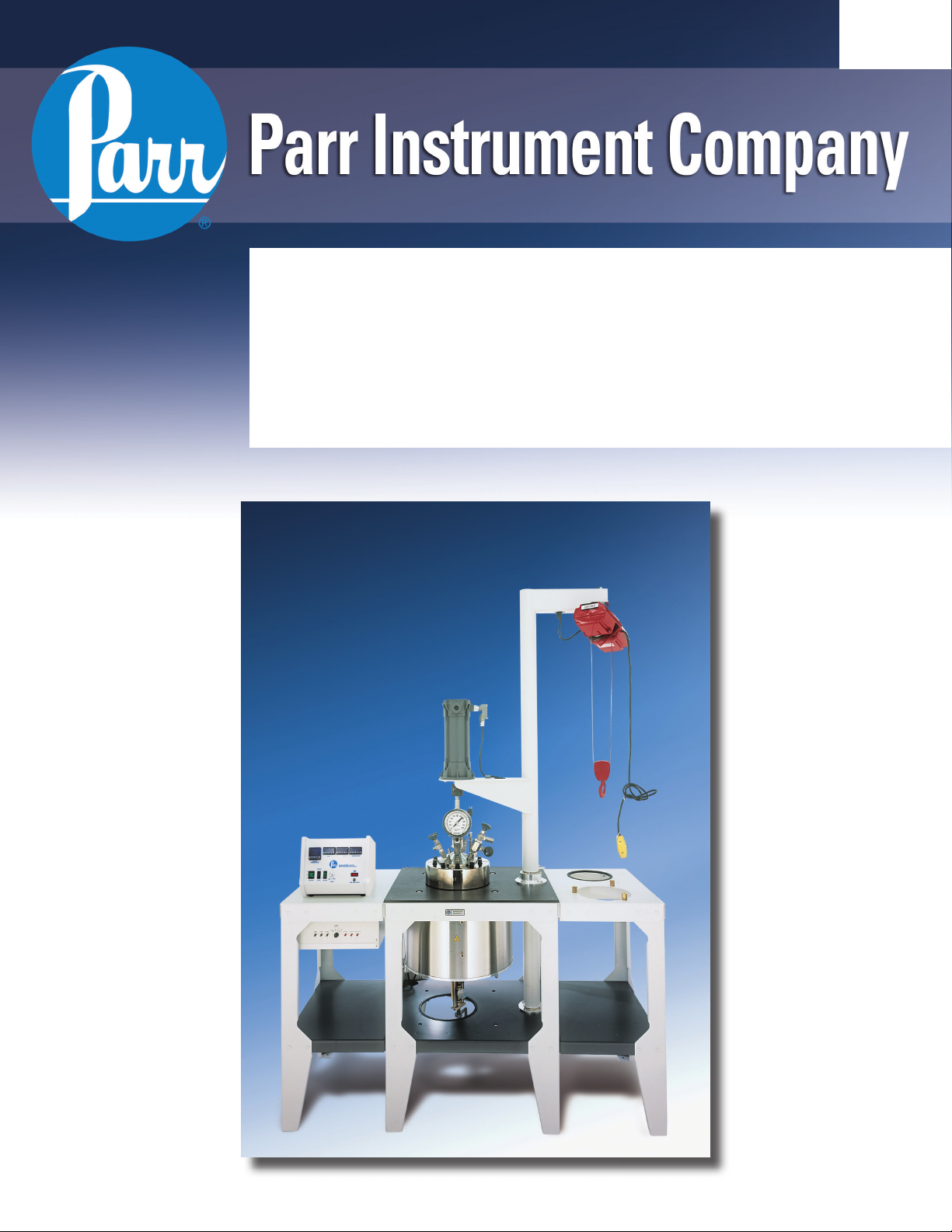
5G & 10L Pressure Reactors
Operating Instruction Manual
403M
Page 2

Page 3

TABLE OF CONTENTS
TABLE OF CONTENTS............................ 2
Related Instructions...........................3
Customer Service.............................. 3
PREFACE ................................................. 4
Scope ................................................ 4
Safety Information ............................. 4
Provisions for Lifting and Carrying.....4
General Specifications....................... 5
Explanation of Symbols..................... 6
Environmental Conditions .................. 6
Intended Usage.................................7
User’s Responsibility.........................7
Unpack Carefully...............................7
INSTALLATION ........................................ 8
Pressure, Temperature Limits ........... 8
Slave Box Control A1761HC3 ........... 8
ASSEMBLE THE REACTOR....................9
Removable Head Vessel................... 9
Fixed Head Vessel .......................... 10
Cylinder Slide Adjustment................ 12
IDENTIFY THE VALVES......................... 13
Gas Inlet Valve................................ 13
Gas Release Valve.......................... 13
Liquid Sampling Valve..................... 13
OTHER VESSEL HEAD FITTINGS ........ 14
Safety Rupture Disc......................... 14
Type J Thermocouple...................... 14
Pressure Gage ................................ 14
Gage and Valve Adapters................14
HOW TO USE THE VESSEL..................15
Flat Gasket or O-ring Seal............... 15
To Open the Vessel......................... 15
Before Closing the Vessel ............... 15
Close the Vessel.............................. 16
Gas Connections............................. 16
Pressurizing the Vessel................... 16
Do Not Overfill.................................17
Releasing Pressure......................... 17
- 2 -
4555 - 58 Series
5G & 10L Pressure Reactors
Withdrawing Liquid Samples............17
The Shaft Seal.................................17
REACTORS WITH SLAVE BOX CONTROLS 18
3-Zone Slave Box A1761HCEE........ 18
3-Zone Slave Box A1761HC3........... 18
Initial Operating Test......................... 18
ACCESSORIES........................................ 19
Internal Cooling Coils........................ 19
Stirrer Drive Systems........................ 19
Quick Disconnect Drive Coupler....... 19
Air Motor...........................................20
Variable Speed Electric Motor ..........20
Spare Parts Kit .................................. 20
EXPLOSION PROOF OPERATION......... 21
The Motor ......................................... 21
The Temperature Controller.............. 21
Slave Box Control............................. 21
The Heater........................................ 21
The Wiring ........................................21
PERIODIC PRESSURE TESTS ............... 22
GENERAL MAINTENANCE NOTES........ 23
Fuses................................................ 24
PARTS LISTS........................................... 25
Vessel Parts List............................... 25
Internal Fittings ................................. 25
External Fittings................................ 26
Internal Parts Identification ............... 27
External Parts Identification..............28
Cooling Coils & Fittings..................... 29
Drive Parts List.................................. 30
Stands............................................... 31
Slave Boxes...................................... 31
Heaters.............................................32
APPENDIX A – REMOVABLE VESSEL
REACTOR DRAWINGS ........................... 33
APPENDIX B – FIXED HEAD VESSEL
REACTOR DRAWINGS ........................... 36
Page 4

4555 - 58 Series
5G & 10L Pressure Reactors
_________________________________
Related Instructions
The following Parr publications are also available to further your understanding of this
instrument and its component parts:
No. Description
201M Limited Warranty
230M Safety Precautions to be observed when operating Pressure Reaction Equipment
231M Operating Instructions for Parr Safety Discs
548M Operating Instructions for 4848 Reactor Controllers
234M Operating and Maintenance Instructions for Parr Magnetic Drives
323M Operating Instructions for Parr Pressure Relief Valves
F0042 Health & Safety Assurance Certification
_________________________________
Customer Service
Questions concerning the installation or operation of this instrument can be answered by the
Parr Customer Service Department:
309-762-7716
800-872-7720
Fax: 309-762-9453
www.parrinst.com
parr@parrinst.com
- 3 -
Page 5

5G & 10L Pressure Reactors
4555 - 58 Series
PREFACE
Scope
These instructions include information for the installation and operation of standard Parr
Models 4555, 4556, 4557, 4558, 4667, and 4668 (5G and 10L volume) Reactors. It should be
noted that these reactors can be custom designed to accommodate a customer’s specific
operating parameters. This may impact certain areas of these instructions or related instructions
mentioned within this manual.
These instructions cover the basic steps to be followed in installing these reactors and
describe the function of all principal components. They are intended to be used in conjunction
with several related instruction sheets listed on the previous page which provide information
describing several components which are common to most Parr pressure reaction apparatus.
These instructions also include safety precautions and other information applicable to all
pressure equipment.
The user should study all of these instructions carefully before starting to use these reactors
to fully understand the capabilities and limitations of the equipment, and to be well aware of the
precautions to be observed in the operation.
Safety Information
To avoid electrical shock, always:
1. Use a properly grounded electrical outlet of correct voltage and current handling capacity.
2. Ensure that the equipment is connected to electrical service according to local national
electrical codes. Failure to properly connect may create a fire or shock hazard.
3. For continued protection against possible hazard, replace fuses with same type and rating of
fuse.
4. Disconnect from the power supply before maintenance or servicing.
To avoid personal injury:
1. Do not use in the presence of flammable or combustible materials; fire or explosion may
result. This device contains components which may ignite such material.
2. Refer servicing to qualified personnel.
Provisions for Lifting and Carrying
The 4555, 4556, 4557, 4559, 4667 and 4668 (five gallon and ten liter volume) reactors and
their components are very heavy. Before moving ensure all cables are disconnected. Use
proper and safe lifting techniques when installing or moving the reactor and/or its components.
Caution
Do not use in hazardous atmospheres.
- 4 -
Page 6

5G & 10L Pressure Reactors
4555 - 58 Series
General Specifications
Electrical Ratings
Controller ratings are found in the Operating Instructions for the controller supplied with your
reactor.
Before connecting any Series A1761HC Slave Control Box to an electrical outlet, the user
must be certain that the electrical outlet has an earth ground connection and that the line, load
and other characteristics of the installation do not exceed the following limits:
Voltage: Fluctuations in the line voltage should not exceed 10% of the rated nominal voltage
shown on the data plate.
Slave Boxes
A1761HCEE rated 230VAC, 50/60 Hz, 50.0 Amp
A1761HC3 rated 400/415V 3-P “Y”, 50/60 Hz, 20.0/ Leg Amp
Frequency: Controllers can be operated from either a 50 or 60 Hertz power supply without
affecting their operation or calibration.
Current: The total current drawn should not exceed the rating shown on the data plate on the
slave control box by more than 10 percent.
Thermocouple: Unless otherwise specified, all Parr controllers operate with a Type J (ironconstantan) thermocouple. The total resistance of the thermocouple and the lead wires should
not exceed 20 ohms. If the resistance of the thermocouple circuit is higher, it will reduce the
sensitivity of the control system.
- 5 -
Page 7
Explanation of Symbols
4555 - 58 Series
5G & 10L Pressure Reactors
I
O
~
3 ~
On position
Off position
Alternating current (AC)
Three–phase alternating current
This CAUTION symbol may be present on the Product
Instrumentation and literature. If present on the product, the
user must consult the appropriate part of the accompanying
product literature for more information.
This CAUTION symbol indicates that the surface may be hot.
Protective Earth (PE) terminal. Provided for connection of
the Protective Earth (green or green/yellow) supply system
conductor.
Environmental Conditions
This apparatus is to be used indoors. It should be secured to the floor in a well-ventilated
area with convenient access to an electric outlet, running water and a drain.
Operating: 15 °C to 35 °C; maximum relative humidity of 80% non-condensing.
Installation Category II (overvoltage) in accordance with IEC 664. Pollution
degree 2 in accordance with IEC 664.
Altitude Limit: 2,000 meters.
Storage: -25 °C and 65 °C; 10% to 85%
relative humidity.
- 6 -
Page 8

5G & 10L Pressure Reactors
4555 - 58 Series
Intended Usage
This system has been designed for use as a high pressure reactor system. It has been
designed, built, and tested to strict physical and electrical standards. Ho wever, it is the user's
responsibility to install and operate it in conformance with local pr essure and electrical codes.
If this equipment is used in a manner beyond its intended usage, the protection provided by
the equipment may be impaired.
User’s Responsibility
All Parr reactors and pressure vessels are designed and manufactured with great care to
assure safe operation when used within their prescribed temperature and pressure limits.
But . . . the basic responsibility for safety when using this equipment rests entirely with the user;
who must:
1. Select a reactor or pressure vessel which has the capability, pressure rating, corrosion
resistance and design features that are suitable for its intended use. Parr engineers will be
glad to discuss available equipment and material options with prospective users, but the final
responsibility for selecting a reactor or pressure vessel that will perform to the user’s
satisfaction in any particular reaction or test must rest with the user – not with Parr.
In exercising the responsibility for the selection of pressure equipment, the prospective
user is often faced with a choice between over - or under-designed equipme nt. The ha zards
introduced by under-designed pressure vessels are readily app arent, but the penalties that
must be paid for over-designed apparatus are often overlooked. Recognizing these criteria,
Parr reactors and pressure vessels are offered in several different styles, each designed for
convenient use in daily operation within certain temperature and pressure limits, using
gaskets, closures and other elements carefully selected for safe operation within the limits
specified for that design. But in order to preserve the validity of these designs, all
temperature and pressure limits must be observed, and no attempt should be m ade to
increase these limits by making alterations or by substituting components which are not
recommended by Parr Instrument Company.
2. Install and operate the equipment within a suitable barricade, if required, with appropriate
safety accessories and in full compliance with local safety codes and rules.
All standard Parr pressure vessels are provided with either a suitable relief device or a
means to attach one (typically in the form of a plugged opening). When a pressure vessel is
delivered without a pressure venting device, it is the customer’s responsibility to provide
pressure relief in order to protect the operator and the equipment from destructiv e high
pressures. If you need more information or need help in selecting a proper re lief device,
please contact Parr Instrument Company.
3. Establish training procedures to ensure that any person handling the equipment knows
how to use it properly.
4. Maintain the equipment in good condition and establish procedu res for periodic testing to
be sure the vessel remains structurally sound.
Unpack Carefully
Unpack the equipment carefully and check all the parts against the, packing list. If shipping
damage is discovered, report it immediately to the delivering c arriers. The vessel, motor, heater,
and temperature controller may be packed separately for convenience in shipping, but these
parts are easily reassembled. Examine the components closely for any lo ose parts or shipping
damage and be sure to check all layers of packing materials thoroughly so as not to overlook
any parts which might otherwise be discarded.
- 7 -
Page 9
5G & 10L Pressure Reactors
4555 - 58 Series
INSTALLATION
Pressure and Temperature Limits
The working pressure and temperature at which any reactor or pressure vessel can be
used will depend upon the design of the vessel and the materials used in its construction.
Since all materials lose strength at elevated temperatures, any pressure rating must be
stated in terms of the temperature at which it applies. The standard material of construction
for Parr Instrument Company is Type 316 Stainless Steel.
Limits for vessels made of other materials and for other operating temperatures can be
obtained from Customer Service. No attempt should be made to increase these limits by
making alterations or by substituting components which are not recommended by the Parr
Instrument Company. It must also be understood that lower pressure and temperature limits
may be required for modified reactors and for vessels made of special alloys.
Limits for vessels will be determined by the physical characteristics of the vessel material
and will be prescribed on an individual basis.
Temperature and pressure limits are also affected by the physical properties and
temperature limits of the gaskets and seals used in the vessel, and by any valves, gages or
other fittings attached to the vessel. Obviously, the safe operating pressure of any system
can be no higher than that of its lowest rated component.
All Parr reactors show the maximum safe operating pressure and temperature imprinted
on the cylinder.
The working pressure and temperature in these five gallon and ten liter reactors must not
exceed the following maximum limits:
Pressure and Temperature Limits
Vessel Material Maximum Pressure Maximum Temperature
T316SS 1900 psig 350° C PTFE Flat Gasket
T316SS 1900 psig 225° C FKM O-ring
T316SS 1900 psig 275° C FFKM O-ring
A1761HC3 400/415V 3-Phase "Y" Slave Box Control
Installation of a 3-phase slave box requires a switch or circuit breaker installed in the
building.
1. It shall be in close proximity to equipment and within easy reach of the operator.
2. It shall be marked as disconnecting device for the equipment.
- 8 -
Page 10
5G & 10L Pressure Reactors
4555 - 58 Series
ASSEMBLE THE REACTOR
These reactors require a work area in a well
ventilated area with convenient access to an electric
outlet, running water and a drain. This unit needs to
be placed at least 10 inches away from walls or
flammable materials.
Use the associated assembly reference drawings
included in this manual to help identify parts to
assemble the reactor.
Removable Head Vessel
1. Take the lift tube assembly with the top
bushings/housings on it and lower the tube through
the work surface and center stand section. Place
the end of the tube over the bottom bushing.
2. If applicable, mount the hoist by hooking it to
the lift tube assembly. If it is an electric hoist, plug it
into receptacle provided in the arm of lift tube
assembly.
3. The wiring for the electric hoist, motor, and tachometer is routed through the lift tube and
out through the bottom bearing support. Route this wiring through the conduit ducts
underneath the center stand bottom shelf and up through the conduit duct on the left rear
leg of the center stand. Connect these wires to the appropriate connectors.
4. Install two Lift Rings (1593HC) in cylinder flange. Attach one Lift Ring (1593HC) into the
Lift Plate (1594HC). Attach two Lift Cables (A1595HC) to the lift plate in the holes that are
180° apart. Attach Lift Cables to the Lift Rings in cylinder. Attach this assembly to the lift
hoist hook. Lift the cylinder and carefully lower into the heater. Remove the two Lift
Rings from the cylinder flange after it is in the heater.
5. If applicable, install the Bottom Drain Valve into bottom of cylinder, through the bottom
of the heater.
6. Lift the head with three Lift Cables (A1595HC) attached to the lift plate in the holes that
are 120° apart. Attach the cables to the three 1571HC Lift Eyes on the head. Lift the head
and place carefully on the cylinder to avoid damage to the sealing surfaces.
7. Install the Split Rings per instructions in section, "How to Use the Vessel".
8. If the drive coupler needs to be adjusted to center the coupler halves, loosen the
mounting bolts of the motor and move the motor assembly as required to center the drive
couplers. Tighten the bolts while holding the motor assembly in position.
- 9 -
Page 11
5G & 10L Pressure Reactors
4555 - 58 Series
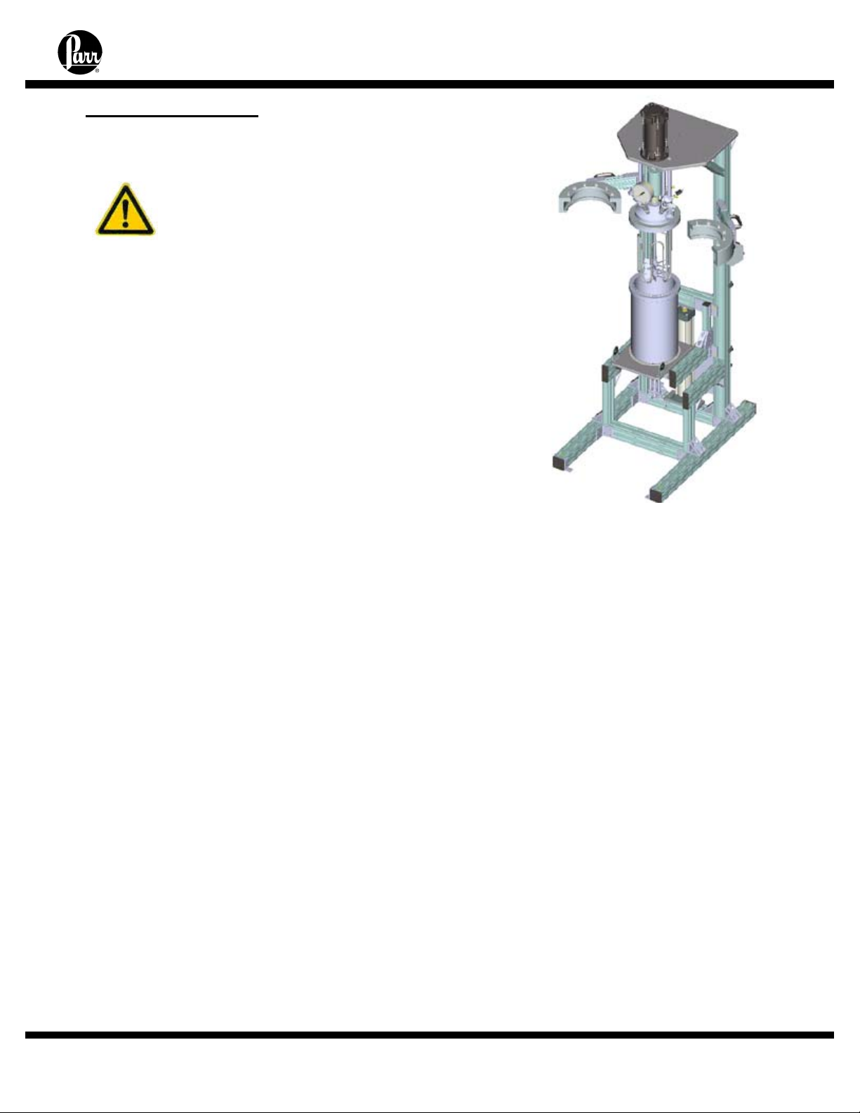
Fixed Head Vessel
Caution Symbols:
1. For the apparatus to be fully stable in all
configurations, the base of this unit must be securely
fastened to the floor before operation. Four 3-hole inside
corner brackets are provided (3159HC). Brackets will
accommodate 5/16” diameter anchoring hardware (not
provided). See drawing A3130HC Basic Main Support
Frame Pkg. shown in Appendix B.
2. See drawing A3140HC Pneumatic Vertical Lift Pkg in
the appendix. Moving parts, potential pinch-point. Keep
hands clear.
3. See drawing A3170HC 2 Hinged Split Ring Pkg in the appendix. Moving parts, potential
pinch-point. Keep hands clear.
Setting up the stand.
1. If the motor has been removed for shipping purposes, reinstall the motor. Refer to
drawings A3160HC and A3160HC2 (pages 43-45).
2. Unpack vessel assembly, remove the split rings, and lift the head assembly from the
cylinder.
3. If furnished with band heaters, install prior to mounting the cylinder.
4. Set cylinder mounting pad on the cylinder support plate. Refer to drawing A3150HC in
the appendix.
5. Handles are provided to assist in lifting the cylinder. Lift the cylinder and place it on the
cylinder support plate, lining up the holes for the retaining bolts. Install retaining bolts. Refer
to drawing A3150HC in the appendix.
6. Set the head assembly on the cylinder carefully to avoid damage to the sealing
surfaces.
7. Push in the cylinder support plate. Install 3 fixed head support rods (3156HC). Refer
to drawing 4557 Sheet 2 in the appendix.
- 10 -
Page 12
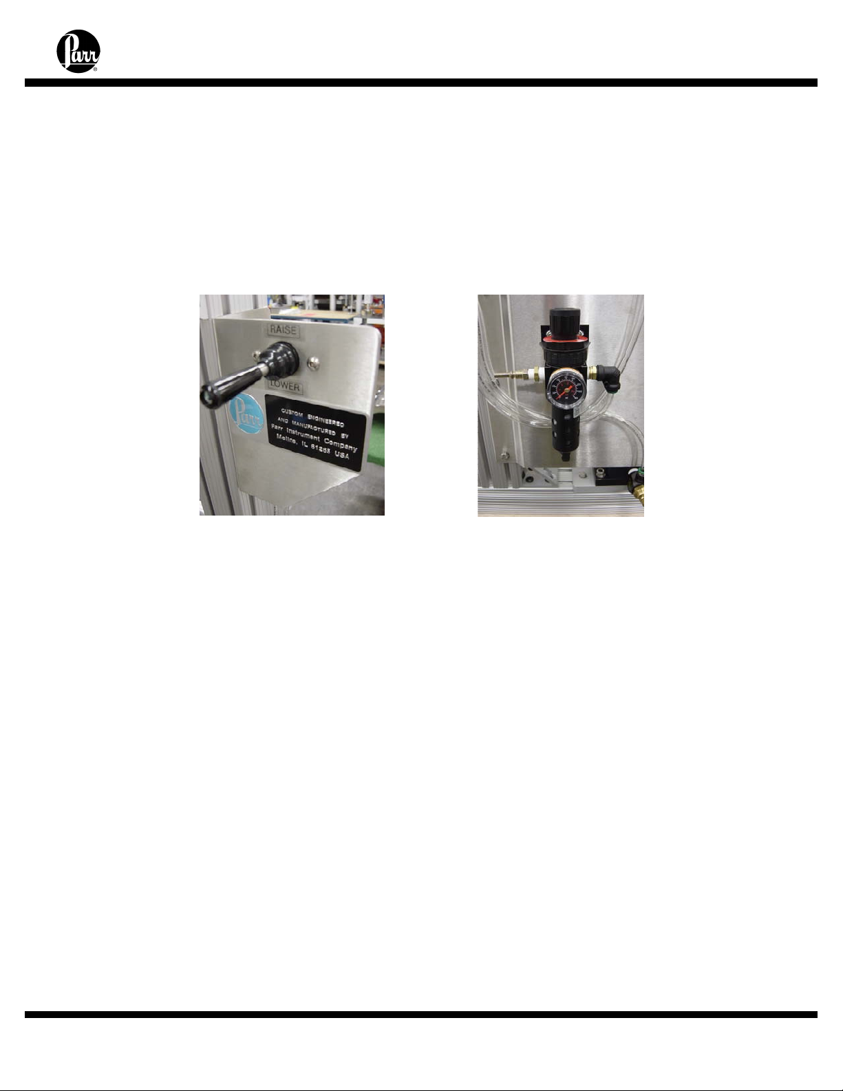
8. Remove the front drive guard shield if applicable. Refer to drawing 4557 Sheet 2 in
the appendix.
9. Connect pneumatics. A quick disconnect fitting has been provided on the back of the
unit for airline connection. User is responsible for providing air source.
10. Lift “up” on joystick to raise cylinder, push “down” to lower. The joystick can provide
speed control up to the maximum preset speed. Lift up slowly to raise the head and
cylinder into position for attaching the fixed head support rods to the upper motor
platform. Refer to drawing 4557 Sheet 2 in the appendix.
11. The lift pressure regulator pressure may need to be increased to raise the additional
weight of the head assembly and cylinder. After the head has been fixed, readjust the
pressure for cylinder weight. The maximum lifting capacity can be adjusted using the
pressure regulator pressure setting. Adjust by lifting up on the top cap and turning clockwise
to increase the amount of pressure being sent to the pneumatic cylinder. Turn
counterclockwise to decrease the amount of pressure. After adjusting, press the cap down
to lock. Depending on vessel size, type, and weight, regulator will be preset at factory for 60
to 80 psi.
12. Ensure the motor coupling and the drive coupler are aligned. If adjustment is
required, loosen the motor bolts to realign and then retighten bolts.
13. Install the front drive guard shield if applicable.
14. Lower the cylinder.
15. If furnished with a flexible mantle heater and/or a bottom drain valve, install at this
time.
5G & 10L Pressure Reactors
4555 - 58 Series
- 11 -
Page 13
5G & 10L Pressure Reactors
4555 - 58 Series
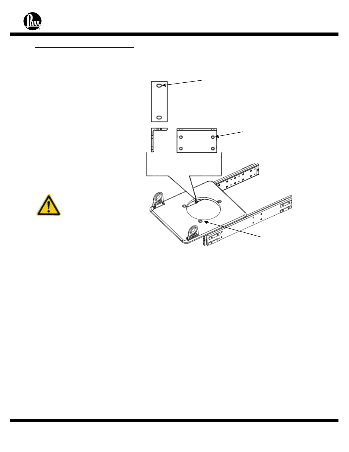
Cylinder Slide Adjustment
Minimal, if any, adjustments
are required for binding or sagging
of the cylinder slide support.
Note: To adjust for sagging, the
cylinder must be removed from the
Slide Support. This can be done
by leaving the closure intact with
the head and cylinder and
removing the (3) 3/8” nuts from the
bottom of the cylinder standoffs.
Lower the support stand
accordingly. This may require
removal of any plumbing devices
or accessories located on the
bottom of the cylinder.
Caution: The
cylinder is very
heavy and caution
should be
observed when the
cylinder is
disconnected from
the Slide Support.
1. Any adjustments to the Slide Support must be made with the Slider Support in the “IN”
position. Adjustments in the “OUT” position can cause unwanted binding to occur.
2. Once the (3) nuts have been removed from the bottom of the Slide Support, the Slide
Support can be lowered. It can then be leveled by loosening the Angle Support Brackets
detailed in the figure F1. Gently loosen the (8) horizontally mounted 5/16 x ¾” fasteners on
the Angle Support Brackets and adjust the Cylinder Support until it is level. Then tighten the
(8) 5/16 x ¾” fasteners accordingly.
3. Loosen the (4) 5/16 x ½” vertically mounted fasteners on the Angle Support brackets
until the support bracket moves freely. Center (left to right) the Slide Support and ensure
that there is no excessive force being applied against or away from the slide rails. Then
tighten the (4) fasteners accordingly.
4. Raise the Slide Support to the bottom of the cylinder until the standoffs are inserted into
the holes provided on the Slide Support. Attach the Slide Support to the cylinder using the
3/8” nuts previously removed.
Slotted holes for
center adjustment
(Left/Right)
(4) 5/16 x 1/2”
Oversized holes for
level adjustment
(Sagging)
(4) 5/16 x 3/4” Bolts
Holes for
cylinder
mounting
(3) 3/8” Nuts and
Flat Washers
- 12 -
Page 14
5G & 10L Pressure Reactors
4555 - 58 Series
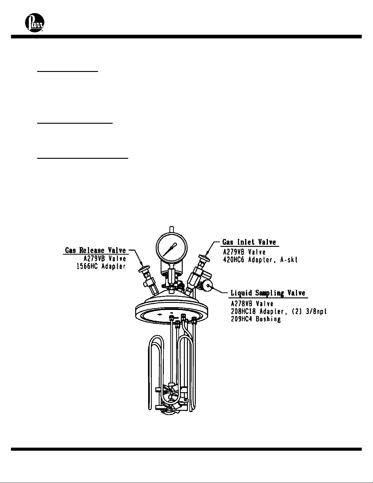
IDENTIFY THE VALVES
Gas Inlet Valve
The gas inlet valve is easily identified when the vessel is open by noting that it is
connected to a dip tube which extends to a point near the bottom of the cylinder. Typically,
this is an angle valve with an attached fitting which provides a socket for attaching the
A495HC pressure hose furnished with the reactor.
Gas Release Valve
The gas release valve is connected to a plain opening on the underside of the head. Gas
released from this valve will be drawn from the top of the reactor.
Liquid Sampling Valve
The liquid sampling valve is attached to the same fitting as the gas inlet valve and
connected to the same dip tube. With this arrangement, incoming gas is always introduced
below the surface of the liquid and the operator is provided with a means for clearing the dip
tube to be sure that any sample taken during a run will be representative of the charge. This
can be done by opening the gas valve momentarily to force any liquid in the dip tube back
into the reactor before withdrawing a sample from the sampling valve.
- 13 -
Page 15
5G & 10L Pressure Reactors
4555 - 58 Series
OTHER VESSEL HEAD FITTINGS
Safety Rupture Disc
There is a safety rupture disc attached to the head which is intended to rupture and
release the pressure before it reaches a dangerous level. A metal tag wired to the safety
head identifies the burst pressure at room temperature for that particular disc. A similar tag
is furnished with each replacement disc. This tag must remain with the apparatus at all
times so that both present and future operators will be aware of the disc rating. Users
should read the discussion of rupture discs given in the Instruction Sheet No. 231M for a
complete description of the characteristics of rupture discs and the precautions to be
observed when operating pressure equipment protected by this type of safety device.
Type J Thermocouple
A Type J thermocouple in a 1/8" dia. stainless steel sheath is furnished with the reactor.
Insert this thermocouple into the head thermowell and connect it to the thermocouple socket
on the rear panel of the temperature controller using the A470E2 extension wire furnished
with the reactor.
Pressure Gage
A pressure gage, typically a 0-2000 psi with a T316 Stainless Steel Bourdon tube, is
mounted on the head using attachment fittings similar to those used for the inlet/sampling
valve assembly
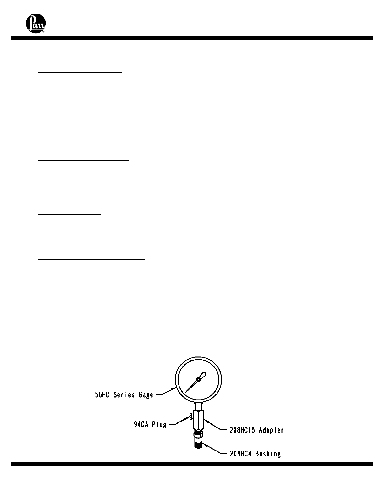
Gage and Valve Adapters
The pressure gage and the combined gas inlet and sampling valves are attached to the
head with an adapter which allows these fittings to be drawn up tightly when facing in any
direction. To attach these fittings to the head, screw the gage or valves firmly into the
adapter, and then run the 209HC4 bushing onto the threaded stem as far as it will go.
Screw this assembly into the head until the nose of the adapter is seated; then back it off
until the valve or gage is facing in the desired direction. Now hold the fitting firmly in place
and close the joint by tightening the 209HC4 bushing. This connection can be made and
broken repeatedly without destroying the sealing faces. A light coating of thread lubricant,
such as Parr No. 424HC2 High Temperature Anti-Seize Lube, applied to the threads and to
the nose of the adapter will help to obtain a tight joint.
- 14 -
Page 16

5G & 10L Pressure Reactors
4555 - 58 Series
HOW TO USE THE VESSEL
The vessels used in Model 4555, 4556, 4557, 4558, 4667 and 4668 Reactors have two
types of closures: fixed head and removable head. They are designed so that the vessel
cylinder and heater can remain together while the head and split rings are attached or
removed.
Flat Gasket or Self Sealing O-ring Closure
The flat gasket is held in a recess in the vessel head and a machine pilot on the cylinder
closes the recess to completely contain the gasket. The split ring closure used with this
gasket has compression bolts which must be tightened to develop loading on the gasket.
The closure is designed so that the compression bolts in the split ring sections must make
contact within a lip on the compression ring which will bring the split sections into their
proper position. When opening these vessels, the compression bolts must be loosened
enough to clear the retaining lip on the compression ring before the split ring sections can
be removed.
The self sealing design features an O-ring retained in a groove on the vessel head. This
design is self sealing and the split ring used with this sealing system does not require nor
have the compression bolts as with the flat gasket.
To Open the Vessel
Open the gas release valve to discharge any internal pressure; then loosen the
compression bolts in the split ring sections (flat gasket design). The split ring sections can
now be removed, and the head with all attached fittings is free to be separated from the
cylinder.
For removable heads, Disconnect the drive by pulling down on the bottom 1743HC
Coupler Halve to disengage the 1746HC Spider from it and swing the lift tube assembly
positioning the lift plate/lift cables over the head and attach the three cables to the lift eyes
in the head until all internal appendages clear the cylinder lip. Rotate the head assembly
around and lower it into the rear service position of the right hand stand assembly. Handle
the head carefully so as not to damage the stirring shaft and other appendages when they
are outside of the cylinder. The cylinder may also be removed from the heater and lowered
into the front service position of the right hand stand assembly.
For fixed heads, slowly and carefully lower the cylinder using the joystick on the
pneumatic lift.
Before Closing the Vessel
Examine the head gasket carefully to be sure that it is in good condition. In flat gasket
designs, after considerable use, some of the PTFE gasket may extrude into a thin, ragged
edge around the inside diameters. This does not necessarily mean that the gasket must be
replaced, but the extruded portion should be removed with a sharp knife. Examine the
mating surfaces on the cylinder and head to be sure they are clean and free from burrs.
- 15 -
Page 17

5G & 10L Pressure Reactors
4555 - 58 Series
Close the Vessel
For removable heads, lift the head carefully from its service position and lower into the
cylinder. Slide the two split ring sections into place. Tighten each of the compression bolts
with the wrench furnished with the apparatus or with a torque wrench. Tightening should
proceed in a crisscross pattern rather than progressively around the circle. Let the vessel
stand for about five minutes after initial tightening; then tighten the cap screws again. This
will compensate for any tendency of the PTFE gasket to flow under the loading pressure.
The recommended bolt torque for sealing a vessel with a PTFE flat gasket is shown in
the chart below. Rotate the drive into position. Connect the drive by pushing up on the lower
coupler halve to engage it into the spider. Make sure the ball detent of the lower coupler
snaps into position.
For fixed heads, raise the cylinder slowly and carefully in to position. Slide the two split
ring halves into place and secure the latches. Tighten the compression bolts in the same
manner as noted above.
Recommended Bolt Torque
10 Liter
Pressure
(psi)
500 psi
1000 psi
1500 psi
1900 psi
Torque
(ft-lb)
25
50
75
100
Recommended Bolt Torque
5 Gallon
Pressure
(psi)
500 psi
1000 psi
1500 psi
1900 psi
Torque
(ft-lb)
35
70
100
135
Gas Connections
Gas connections are dependent on applications. For general usage, use the pressure
hose furnished with the reactor. Screw the Type "A" coned pressure fitting into the adapter
attached to the gas inlet valve and tighten the compression nut firmly. Do not use any
thread dope on the coned fitting. The A495HC pressure hose is made of reinforced Nylon
which can be used for all non-corrosive gases at pressures up to 2500 psig. For operations
involving corrosive gases, this hose should be replaced with an A490HC hose which has a
PTFE lining and a braided stainless steel outer covering. An A506HC all metal hose is also
available in stainless steel and other corrosion resistant materials. All of these hoses have
the same fittings.
Pressurizing the Vessel
Check all valves carefully before admitting gas into the system. The liquid sampling
valve must remain closed throughout the charging procedure. The gas release valve must
also be closed unless the vessel is to be purged, or unless there is to be a continuous flow
through the reactor during a run. Always make certain that the pressure in the gas tank is
greater than the pressure in the vessel; otherwise liquid will be forced out of the vessel and
into the gas tank when the inlet valve is opened. If there is any possibility that the tank
pressure might not be high enough to force gas into the reactor, install a one way check
valve (optional) in the gas line to prevent any reverse flow. With the inlet valve open and the
- 16 -
Page 18

flow control valve on the gas tank closed, open the main valve on the gas tank only about
one-quarter turn; then use the flow control valve or the valve on a pressure regulator to
control the flow of gas into the vessel. After the desired pressure has been reached, close
the tank valves and the vessel inlet valve and disconnect the hose at the vessel end.
5G & 10L Pressure Reactors
4555 - 58 Series
Do Not Overfill the Vessel
Always watch the pressure gage closely when admitting gas so as not to exceed the
maximum working limit. Remember that any subsequent increase in temperature will raise
the pressure. Also, be sure that the amount of liquid placed in the vessel is carefully
controlled. As a general rule, the liquid charge should not exceed two-thirds of the capacity
of the cylinder. Too much liquid in the vessel can lead to development of dangerous
pressures if sufficient space is not provided for expansion when the liquid is heated. This
hazard is explained in greater detail in a warning statement included in the Safety
Instruction Manual No. 230M.
Releasing Pressure
Use the gas release valve to reduce the pressure in the vessel if the reactor is
accidentally overcharged when filling. Use this valve also to release any excess pressure
during a run and to exhaust the vessel at the end of a run. If the discharge gases are
flammable or toxic, discharge to an exhaust hood or to any other safe release point.
Withdrawing Liquid Samples
Liquid samples may be withdrawn from the sampling valve attached to the same adapter
as the gas inlet valve whenever the vessel is pressurized. Always close the inlet valve
before withdrawing a liquid sample and open the sampling valve cautiously because liquid
will be discharged with considerable force. Be particularly careful if the temperature of the
sample is above its boiling point at atmospheric pressure. If so, it will “flash” and be lost as
soon as it is released from the vessel. This problem can be avoided by connecting an
optional 4351 Sample Collection Vessel to the sampling valve to collect the liquid into an
appropriate receiver. The addition of a small amount of gas can be used to clear the dip
tube between liquid samples so that the next sample drawn through the tube will truly be
representative of the mixture.
The Shaft Seal
The stirrer shafts on these reactors are sealed with a magnetically coupled gland.
Operating and Maintenance instructions for these are provided in Instruction Manual No.
234M.
- 17 -
Page 19

5G & 10L Pressure Reactors
4555 - 58 Series
REACTORS WITH SLAVE BOX CONTROLS
Reactors can be set up with a wide variety of heaters. Single zone flexible mantle type
heaters or 3-zone ceramic fiber, band or aluminum block type heaters can be used
depending on the customer’s requirements. For the high powered 3-zone type heaters, Parr
Instrument Company offers a series of slave box controls. Having zone control allows a
wide range of heating power to be selectable by the operator. These slave controls are used
in conjunction with the 4848M Master Controllers.
Note- 3-Zone Heater locations are traditionally:
Zone 1 = Bottom Heater
Zone 2 = Middle Heater
Zone 3 = Top Heater
A1761HCEE 3-Zone Slave Control Box
The A1761HCEE slave control box is supplied with a 250 volt, 50 amp (NEMA 6-50P)
power plug. A 230 volt, 50 or 60 Hz, single phase power supply capable of a maximum
current draw of 40 amperes is required.
The A1761HCEE slave control box has 3 heater outputs each corresponding with a
respective heated zone. There is a 4 position selectable switch, on the front panel, which
can switch the heaters off or turn on zone 1, zones 1 and 2, or zones 1, 2 and 3.
Also located on the front panel are 3 manual reset, high limit switches. These switches
will trip if an alarm condition is present on the master controller. Once the alarm condition
has been resolved, ensure the selector switch is in the “off” position, and reset each switch
by pushing in each button until it latches. These switches may have to be set when the unit
is first powered on.
A1761HC3 3-Zone Slave Box Control
The A1761HC3 slave control box is supplied with an IEC 60309, 5 pin, 32 amp power
plug. A 400 to 415 volt, 3-phase power supply wired in a 5-wire WYE configuration capable
of supplying a maximum of 20 amperes is required.
The A1761HC3 slave control box has 3 heater outputs each corresponding with a
respective heated zone. There is a 4 position selectable switch, on the front panel, which
can switch the heaters off or turn on zone 1, zones 1 and 2, or zones 1, 2 and 3.
Also located on the front panel is a manual reset, high limit switch. This switch will trip if
an alarm condition is present on the master controller. Once the alarm condition has been
resolved, ensure the selector switch is in the “off” position, and reset the switch by pushing it
upwards until it latches. This switch may have to be set when the unit is first powered on.
Initial Operating Test
Read all operating instructions carefully so as to be well acquainted with the correct
procedures for handling the vessel and for operating the controller and other accessories.
An initial operating test should be made, with only water, to check the apparatus before
starting the first experimental runs. For this initial test, fill the cylinder not more than half-full
of water and run the temperature up to 150 °C while checking the apparatus for leaks and
observing the performance of the temperature controller.
- 18 -
Page 20

5G & 10L Pressure Reactors
4555 - 58 Series
ACCESSORIES
Internal Cooling Coils
Cooling coils can be installed in any of these reactors. Reactors purchased without a coil
can have this feature added by ordering the appropriate parts from Parr Instrument
Company.
Cooling coils are made in serpentine configurations. A serpentine coil does not interfere
with the use of a liner. Plugs are available to seal the cooling coil opening when the coil is
not used.
Replacement coils are furnished with excess tubing at the ends to allow for any
adjustments that might be required when installing a new coil. Align the replacement coil
with the internals before retightening the connections. Remove any sharp burrs and attach
the elbow connectors. Use only moderate force when tightening these elbows so that the
ferrules will not be crimped too deeply into the tube. If tightened too hard it will be difficult to
remove the brass ferrules without damaging the tube, making it impossible to reuse the coil
after it has been removed from the vessel head.
Stirrer Drive Systems
Two types of drive systems are available on the 4555 Series Reactors. They are the
direct drive and the gearbox drives. The direct drive has the motor mounted vertically above
the reactor with the drive coupler connected to the motor shaft. This will produce speeds
from 0 to 1700 RPM. The gearbox drive is offered with three different speed ranges. They
are 3:1 ratio, 5:1 ratio, and 10:1 ratio. These are usually used in low RPM, high stirring load
applications.
Quick Disconnect Drive Coupler
The top coupler half is stationary mounted with a set screw to the drive motor shaft. The
bottom coupler half provides vertical movement for quick disconnect of the couplers. The
bottom coupler is held in the up or engaged position by a spring loaded ball that rests in a
detent in the square drive key. The spring loaded ball inside the threaded hole in the bottom
coupler half and is adjustable to obtain the necessary force to hold coupler in drive or
engaged position.
Removable vessel only: If the coupler needs to be adjusted to align the coupler halves
over each, either relocate the drive motor or the overarm plate or, on moveable vessel
designs, loosen the mounting bolts of the 1578HC Top Bearing Housing and move the
A1575HC Series Welded Overarm Assembly as required to align the drive couplers. Tighten
the mounting flange bolts while holding the welded overarm assembly in position.
- 19 -
Page 21

5G & 10L Pressure Reactors
4555 - 58 Series
Air Motor
Variable stirring speeds from 100 to 2000 rpm can be obtained by replacing the standard
motor with a 1678HC air motor. This motor operates on compressed air which must be
supplied at 20 psig minimum pressure with at least 10CFM available at that pressure. It is
furnished with a speed control valve and oiler, all assembled on a mounting bracket.
To operate reactors equipped with an air motor, mount the drive system firmly on the
heater and connect the air hose to a compressed air line. Fill the oiler with SAE 10 oil and
adjust the oiler to feed one drop per minute into the air stream. For long continuous runs at
high speeds the oiling rate should be increased to three drops per minute.
If the motor becomes sluggish, flush it with a non-flammable solvent in a well ventilated
area. Disconnect the airline and muffler and pour a small amount of solvent into the inlet
port. Rotate the shaft by hand in both directions for a few minutes; then connect the air line
and run the motor until there is not further trace of solvent in the exhaust. If the muffler felts
are dirty, wash them in solvent or replace them. Re-lubricate the motor with a squirt of oil
into the chamber and reassemble. If it becomes necessary to disassemble the motor to
replace the vanes, follow directions given in the instruction sheet published by the Gast
Manufacturing Corp., Benton Harbor, Michigan.
Variable Speed Electric Motor
Reactors are normally equipped with a DC variable speed motor supplied and controlled
through the 4848M/A3600HC_Series controller. Instructions for connecting and operating
these motors are included in the controller Instruction Manual No. 548M. This motor is
usually installed in a drive system designed to produce stirring speeds up to 1700 rpm.
Spare Parts Kit
Parr can furnish spare parts kits for these reactors which will provide a reserve supply of
parts and tools sufficient to handle most normal replacements and emergency repairs during
a year of heavy usage. These kits contain replacement gaskets, packing, O-rings, shafts,
bearings, and rupture discs. They can be ordered from any Parr Dealer or direct from Parr
Instrument Company. The order must specify the reactor size and indicate type of rupture
disc, stirrer drive. It is advantageous to provide the serial number stamped on the vessel
head or cylinder.
- 20 -
Page 22

5G & 10L Pressure Reactors
4555 - 58 Series
EXPLOSION PROOF OPERATION
If the local safety code requires that equipment installed in the user’s laborat ory must be
explosion proof, there are five possible ignition hazards to be considered:
1. The Motor
The standard variable speed motor is not explosion proof, yet these motors are not unduly
hazardous if operated in a well ventilated location where care is taken to prevent the
accumulation of explosive gases or vapors. To eliminate any possible spark hazard originating
at the motor, Parr can furnish an air motor as described above, or the reactor can be equipped
with a variable speed, encased electrical explosion proof motor which is approved for use in
Class 1, Groups C & D, and Class 2, Groups E, F, & G atmospheres. Explosion proof m otors
are furnished with a temporary power cord and plug which are not explosion proof. The user
should remove this temporary wiring and replace it with an explosion proof wiring as required to
comply with the local electrical code.
2. The Temperature Controller
The 4848M/A3600HC_Series Temperature Controllers furnished with these reactors contain
switches and other elements which are not explosion proof. The mini mal spark hazard
associated with these units can be resolved by installing the controller in a re mote location
outside of the hazardous area or by enclosing it in an approved explosion proof h ousing. If
enclosed within a positive pressure, clean air housing, the discharge from the housing must be
directed into a safe area. If requested, Parr will furnish the long lead wires needed to mount th e
controller in a remote location. If the controller is to be installed in an explosion proof housing,
the user must provide the necessary housing and installation.
3. Slave Box Control
Reactors furnished with 3-zone high power heaters are supplied with a slave control box.
These slave boxes also contain switches and other elements that are not explo sion proof. The
minimal spark hazard associated with these units can be resolved by installing the controller
and slave box in a remote location outside of the hazardous area or b y enclosing it in an
approved explosion proof housing. If enclosed within a positive pressure, clean air housing, the
discharge from the housing must be directed in to a safe area. If requested, Parr will furnish the
long lead wires needed to mount the controller and slave box in a rem ote location. If the
controller is to be installed in an explosion proof housing, the user must prov ide the necessary
housing and installation.
4. The Heater
The elements in the heater could be dangerous in an explosive atmosphere if the surface
temperature of the element becomes high enough to ignite flammable vapors. This hazard must
be evaluated for each individual installation since major modifications are required if the heater
must be isolated from the surrounding atmosphere. Users who consider this a significant hazard
are urged to contact Parr Instrument Company for further discussion and sugge stions which
might be helpful. Parr is currently offering aluminum block heaters (4555 on ly) and circulating
jacketed cylinders which have been used in explosive environments.
5. The Wiring
Unless specifically designed for use in hazardous atmospheres, the wiring in these reactors
will not meet the standards prescribed for explosion proof equipment. Optional, intrinsically safe
barriers are available.
- 21 -
Page 23

5G & 10L Pressure Reactors
4555 - 58 Series
PERIODIC PRESSURE TESTS
Each cylinder used in a Parr stirred reactor is tested under hydrostatic pressure to 1.3
times its maximum rating before it is released from the factory. Micrometer caliper
measurements are taken during this test to check the deflection of the cylinder walls under
pressure. Excessive deflection or failure of the metal to resume its original dimension after
pressure is released indicates that a cylinder is potentially unsafe and it will be rejected.
Similar tests should be made at regular intervals during the life of each cylinder, and
particularly whenever the user suspects that the equipment has been over-stressed or
damaged.
Some laboratories maintain hydraulic test facilities and make it a rule that all pressure
vessels must be tested at regular intervals. Records are kept of deflections at specific test
pressures so that any increase in deflection becomes a warning that the metal has lost
strength. Any cylinder which fails to return to its original dimensions after application of the
prescribed hydrostatic test should be discarded as unsafe for further use.
Users who do not have pressure test facilities can return any Parr pressure vessel to the
factory for hydrostatic testing and overhaul. This should be done whenever the metal shows
excessive damage from corrosion or whenever an over-pressure or other unusual
occurrence raises any safety questions. To return a vessel for repair, contact Parr
Instrument Company for a return authorization number. Apparatus returned for testing and
overhaul should be shipped prepaid to the Parr Instrument Company, 211-53rd Street,
Moline, Illinois 61265. An order or letter of instructions should be mailed to the same
address, as no repair work will be started without specific instructions and a Health & Safety
Assurance Certification form (F0042) signed by a responsible user.
- 22 -
Page 24

5G & 10L Pressure Reactors
4555 - 58 Series
GENERAL MAINTENANCE NOTES
1. Periodically inspect all electrical wiring and pressure connections for excessive corrosion
or wear. Suspect parts should be replaced by components only supplied by Parr Instrument
Company.
2. Always use appropriate wrenches on all fittings and valves. Never use pliers or pipe
wrenches.
3. Head and cylinder service fixtures are available for convenience and protection of
components during maintenance of your reactor.
4. To reinstall straight thread (NPS) fittings to the head, screw the gage or valves firmly into
the adapter. Run the bushing onto the threaded stem as far as it will go. Screw this
assembly into the head until the nose of the adapter is seated; then back it off until the valve
or gage is facing in the desired direction (no more than one full turn). Hold the fitting firmly in
place and close the joint by tightening the bushing. This connection can be made and
broken repeatedly without destroying the sealing surfaces. A light coating of thread
lubricant, such as Parr High Temperature Anti-Seize Lubricant, applied to the straight
threads and to the nose of the adapter will help to obtain a tight joint. Note: PTFE tape
should be used only on all tapered (NPT) threads, not NPS straight threads.
5. NPT (National Pipe Taper) threads should not be disassembled any more than
necessary. It will become increasingly difficult to maintain a tight seal with these tapered
threads if the joint is made and broken repeatedly.
6. Do not use oil or anti-seize lubricant on threads or fittings if the vessel is to be used with
oxygen.
7. If your vessel is equipped with a loose compression ring, be sure that it is in place on the
head before attaching any head fittings. The compression ring cannot be installed after
fittings have been screwed into the head.
8. Clean all threads and gas passages thoroughly and remove all tape fragments when
overhauling a vessel. An ultrasonic bath is excellent for cleaning metal parts, but do not
place a thermocouple probe, pressure gage, face seals or ball bearings in an ultrasonic
bath. Periodic cleaning may be performed on the exterior surfaces of the reactor stand with
lightly dampened cloth containing mild soap solution. All power should be disconnected
when cleaning.
9. Routinely inspect cap screws on split ring closure for lubrication and cleanliness. It is
important to clean and lubricate periodically with Parr High Temperature Anti-Seize
Lubricant so that the required torque is accurately applied.
- 23 -
Page 25

10. To operate reactors equipped with an air motor, connect air hose to a compressed air
line. For best torque and speed control the piping to the motor should be at least 3/8" IPS or
larger. Fill the oiler with SAE 10 oil and adjust the oiler feed to a rate of one drop per minute
into the air stream. For long continuous runs at high speeds, the oiling rate should be
increased to three drops per minute.
If the motor becomes sluggish, flush it with a non-flammable solvent in a well ventilated
area. Disconnect the air line and muffler and pour a small amount of solvent into the inlet
port. Rotate the shaft by hand in both directions for a few minutes; then connect the air line
and run the motor until there is not further trace of solvent in the exhaust. If the muffler is
dirty, replace it. Re-lubricate the motor with a squirt of oil into the chamber and reassemble.
11. If servicing assistance is needed, contact Parr Instrument Company directly at the
address shown on the back of these instructions
5G & 10L Pressure Reactors
4555 - 58 Series
Fuses
The replacement of protective fuses should be performed by qualified personnel.
Note: Check the labels on the instrument for correct fuse rating.
Parr Part # Description Slave Box Type Ratings
1535E Heater Fuse A1761HC3 KAC 25 Amps, 600VAC
185E
2094E Heater Fuse A1761HCEE Fast-Acting 25 Amps, 250VAC
2093E Main Fuse A1761HCEE Fast-Acting 50 Amps. 250 VAC
139E8 Lift Fuse A1761HCEE Slo-Blo 2.5 Amps, 250VAC
Master
Controller Fuse
A1761HC3 Slo-Blo 5 Amps, 250VAC
- 24 -
Page 26

5G & 10L Pressure Reactors
4555 - 58 Series
PARTS LISTS
Vessel Parts List
Consult the itemized list of part numbers provided with your reactor.
For parts made from alternate materials the following suffixes are used:
CA - Titanium CH – Alloy C-276 CT - Inconel CC – Alloy 20Cb3
CG – Alloy B-2 CM - Monel CX - Zirconium
1557HC Series 5G Flat Gasket 1559HC 5G Flat Gasket PTFE
3187HC Series 5G O-ring Seal 3184HCJV 5G O-ring Seal FKM
2957HC Series 10L Flat Gasket 2959HC 10L Flat Gasket PTFE
3197HC Series 10L O-ring Seal 3194HCJV 10L O-ring Seal FKM
CYLINDERS SPLIT RINGS-MOVABLE
1555HC Series 5G Flat Gasket A1556HC 5G Flat Gasket
3185HC Series 5G O-ring Seal A3186HC 5G O-ring Seal
2955HC Series 10L Flat Gasket A2956HC 10L Flat Gasket
3195HC Series 10L O-ring Seal A3196HC 10L O-ring Seal
SPLIT RINGS-FIXED HEAD COMPRESSION RINGS
A1556HC2 5G Flat Gasket 1554HC 5G Flat Gasket
A3186HC3 5G O-ring Seal N/A 5G O-ring Seal
A2956HC2 10L Flat Gasket 2954HC 10L Flat Gasket
A3196HC2 10L O-ring Seal N/A 10L O-ring Seal
ACCESSORIES
1556HCF Compression Bolts
1571HC Lift Eye (Head)
1593HC Lift Ring (Cylinder)
891DD 5/8” Comb. Wrench
Internal Fittings
Thermowell
265HC15 Thermowell, 5G 15.94”L
265HC10 Thermowell, 10L 12.12”L
48HC Thermowell, Gasket, Silver
48HCFG Thermowell, Gasket, Gold (for Special Alloy)
Dip Tube
1567HC Series Inlet (Dip) Tube
275VBAD Male Connector to hold tube
HEADS HEAD SEAL
- 25 -
Page 27

5G & 10L Pressure Reactors
Internal Fittings continued
Shafts
1025HC28 Upper Stub Shaft 5G Magnetic Drive
A1030HC27 Lower Shaft Assembly 5G Magnetic Drive
1025HC45 Upper Stub Shaft 10L Magnetic Drive
A1030HC44 Lower Shaft Assembly 10L Magnetic Drive
2135HC9 Shaft, 5G, Footless Magnetic Drive
2135HC21 Shaft, 10L, Footless Magnetic Drive
Impellers
1569HC Impeller, 5G, Magnetic Drive
709HC Impeller, 10L, Magnetic Drive
A2138HC3 Impeller, 5G, Footless Magnetic Drive
A2138HC2 Impeller, 10L, Footless Magnetic Drive
709HCF Impeller Screw, ¼-20 thread (for all the above)
Stirrer Support Brackets
A1570HC Support Bracket, 5G
A380HC3 Support Bracket, 10L
380HCF Bolt, 5/16-18 thread (for all the above)
External Fittings
94CAAD Plug, Hex Head, 1/4NPTM, T316SS
A278VBAD Valve, Straight 3/8" NPTM (Liquid Sampling)
A279VBAD Valve, Angled 3/8" NPTM x 3/8" NPTM (Gas Release)
A279VBAD Valve, Angled 3/8" NPTM x 3/8" NPTM (Gas Inlet)
420HC6 Adapter, 3/8" NPTF x A socket (Inlet Hose)
1566HC Adapter, 3/8" NPTM x 3/8" NPTF (Gas Release)
208HC18 Valve Adapter, two 3/8" NPTF (Gas Inlet/ Liquid Sampling)
208HC15 Gage Adapter, two 1/4" NPTF
209HC4 Bushing for gage and valve adapters
56HC Series Gages, 4-1/2”, psi/bar
664HC3 Magnetic Stirrer Plug (optional – use with 663HC olive)
A472E5 Thermocouple, Grounded Type J, 21-1/2"
A511E2 Thermocouple, Type J, Bayonet
A707HC2 Safety Rupture Disc Assembly without disc (See 231M)
A1750HC* Magnetic Drive (See 234M)
A1750HC2* Double Magnetic Drive Assembly (See 234M)
A2170HC* Footless Magnetic Drive (See 234M)
A2170HC2* Double Footless Magnetic Drive Assembly (See 234M)
664HC Nut, Gland, Magnetic Drive seal
663HC* Olive, Magnetic Drive seal
2136HC Gasket, Footless Magnetic Drive
A740HC Cooling Sleeve for Magnetic Driv e Assemblies
715HC O-ring, NBR (for Cooling Sleeve)
716HC Quick Disconnect (for Cooling Sleeve)
4555 - 58 Series
- 26 -
Page 28

Internal Parts Identification
4555 - 58 Series
5G & 10L Pressure Reactors
4556 / 4558 10 L
4555 / 4557 5 Gallon
- 27 -
Page 29

External Parts Identification
4555 - 58 Series
5G & 10L Pressure Reactors
- 28 -
Page 30

Cooling Coils & Fittings
1568HC Serpentine Cooling Coil, 3/8T, 5G
2968HC Serpentine Cooling Coil, 3/8T, 10L
276VB Male Connector, 3/8T x 3/8NPTM Bored Thru
428VB Female Elbow, 3/8T x 1/8NPTF
A92HWBB Male Connector, 1/8 NPTM x 1/4T, Brass
122HW Ferrule, Brass 1/4T (for A92HWBB)
4555 - 58 Series
5G & 10L Pressure Reactors
- 29 -
Page 31

Drive Parts List
Motor
A388E2ES Motor, 1/2 HP VS 90VDC
A388E2EQ Motor, 1/2 HP EXP VS 90VDC
A388E2ER Motor 1/2 HP EXP VS 180VDC
A388E2ET Motor 1/2 HP VS 180VDC
A388E3ER Motor 3/4 HP EXP VS 180VDC
A388E3ET Motor 3/4 HP VS 180VDC
1678HC Air Motor
Shaft Couplings
1743HC Chamfered Coupling Half
1744HC Machined Coupling Half
1746HC Spider
Optional Tach Parts
1564HC Optical Wheel
A1060E Tach Sensor Assembly 5G/10L Removable Vessel
A1001E9 Tach Sensor Assembly 5G/10L Fixed Head Vessel
A1177E Optical Tach Harness (10 ft)
Lift System (Removable Vessel Only)
A1575HC Lift Tube Assembly , Direct Drive
A1575HC2 Lift Tube Assembly, Gear Box Drive
A1574HC Lift Tube Assembly, Non-Stirred
1578HC Housing, Bearing; Aluminum Top
1579HC Housing, bearing; Aluminum Bottom
1580HC Bushing, Brass; Top
1581HC Bushing, Brass; Bottom
1593HC Lift Ring, Cylinder
A1595HC Plate, Lift (Stirred)
1594HC Plate, Lift (Non-Stirred)
1680HC Spacer
1743HC Chamfered Coupling Half
1746HC Spider, Coupling
1744HC Machined Coupling Half
1766HC Grommet, insulating
4555 - 58 Series
5G & 10L Pressure Reactors
- 30 -
Page 32

5G & 10L Pressure Reactors
Stands
Stand Parts (Fixed Head Vessel)
A2760HC2 Pneumatic Lift Package with Regulator, Hand Lever & Tubing
3174HC Shield, Magnetic Drive
2446HC Thumb Screws for Shield
3154HC Cylinder Mounting Pad
2548HC3 Lift Handle
2759HC Lift Handle Grommet
1743HC Chamfered Coupling Half
1746HC Spider, Coupling
1744HC Machined Coupling Half
Slave Boxes
Parts Used in A1761HCEE Slave Boxes
139E8 Fuse, Slo-blo, 250V 3AG
2094E Fuse, Fast-Acting, 250 vac, 25 amp
2092E Fuse Holder
2093E Fuse, Fast-Acting, 250 vac, 50 amp
2095E Fuse Holder
542E Circuit Breaker, .08 Amp
1119E Relay, 25 Amp
Parts Used in A1761HC3 Slave Box
185E Fuse, Slo-blo, 250V
1119E Relay, 25 Amp
1524E Circuit Breaker
1535E Fuse
1536E Fuse Holder
4555 - 58 Series
- 31 -
Page 33

5G & 10L Pressure Reactors
Heaters
A1590HCEE 3-Zone Ceramic Heater Assembly (Removable Vessel)
83E Locknut
460E3EE Cord Set Hi-Temp
A491E3 Cord Grip
509E Connector, Bayonet
1006EEE Element, Heater
1883HC Guide Tube, Thermocouple
1582HC Tie Bolt
1583HC Header, Top
1585HC2 Header, Bottom
1586HC2 Disc, Bottom
ME1587HC Shell, Outer
1588HC Outlet Box
1589HC Cover, Outlet Box
A1755HC2EE 3-Zone Aluminum Block Heater Assembly (Removable Vessel)
460E3EE Cord Set
A491E2 Cord Grip
A776E2EE Heater, Cast Alum
783E Plug, ½ NPT
787E Seal
791E2 Nipple 1.5”L
791E4 Nipple 2.5”L
791E6 Nipple 3.5”L
795E Elbow, Capped
797E Packing Fiber
798E Sealing Compound
1582HC Tie Bolt
1665E Coupler
1749HC Top Header
1783HC Insulating Jacket
1777HC Tee Hub
1778HC Cross Hub
1780HC Nipple, 8”L
1813HC Ceramic Wire Nut
1914HC Ceramic Wire Nut
Band Heaters (Fixed Head Vessel)
A1930EEE Band Heater 5G (Standard), 2000W
A1930E2EE Band Heater 5G (Hi-Temp), 2000W
A1932EEE Band Heater 10L (Standard), 1200W
A1932E2EE Band Heater 10L (Hi-Temp), 1200W
4555 - 58 Series
- 32 -
Page 34

5G & 10L Pressure Reactors
4555 - 58 Series
APPENDIX A – REMOVABLE VESSEL REACTOR DRAWINGS
- 33 -
Page 35

5G & 10L Pressure Reactors
4555 - 58 Series
APPENDIX A – REMOVABLE VESSEL REACTOR DRAWINGS
- 34 -
Page 36

5G & 10L Pressure Reactors
4555 - 58 Series
APPENDIX A – REMOVABLE VESSEL REACTOR DRAWINGS
- 35 -
Page 37

5G & 10L Pressure Reactors
4555 - 58 Series
APPENDIX B – 5-GALLON, FIXED HEAD VESSEL REACTOR DRAWINGS
- 36 -
Page 38

5G & 10L Pressure Reactors
4555 - 58 Series
APPENDIX B – 10-LITER FIXED HEAD VESSEL REACTOR DRAWINGS
- 37 -
Page 39

5G & 10L Pressure Reactors
APPENDIX B – FIXED HEAD VESSEL REACTOR DRAWINGS
4555 - 58 Series
- 38 -
Page 40

5G & 10L Pressure Reactors
APPENDIX B – FIXED HEAD VESSEL REACTOR DRAWINGS
4555 - 58 Series
- 39 -
Page 41

5G & 10L Pressure Reactors
APPENDIX B – FIXED HEAD VESSEL REACTOR DRAWINGS
4555 - 58 Series
- 40 -
Page 42

5G & 10L Pressure Reactors
APPENDIX B – FIXED HEAD VESSEL REACTOR DRAWINGS
4555 - 58 Series
- 41 -
Page 43

5G & 10L Pressure Reactors
APPENDIX B – FIXED HEAD VESSEL REACTOR DRAWINGS
4555 - 58 Series
- 42 -
Page 44

5G & 10L Pressure Reactors
APPENDIX B – FIXED HEAD VESSEL REACTOR DRAWINGS
4555 - 58 Series
- 43 -
Page 45

5G & 10L Pressure Reactors
APPENDIX B – FIXED HEAD VESSEL REACTOR DRAWINGS
4555 - 58 Series
- 44 -
Page 46

5G & 10L Pressure Reactors
APPENDIX B – FIXED HEAD VESSEL REACTOR DRAWINGS
4555 - 58 Series
- 45 -
Page 47

5G & 10L Pressure Reactors
APPENDIX B – FIXED HEAD VESSEL REACTOR DRAWINGS
4555 - 58 Series
- 46 -
Page 48

Revision 11/16/12
 Loading...