

Page 1
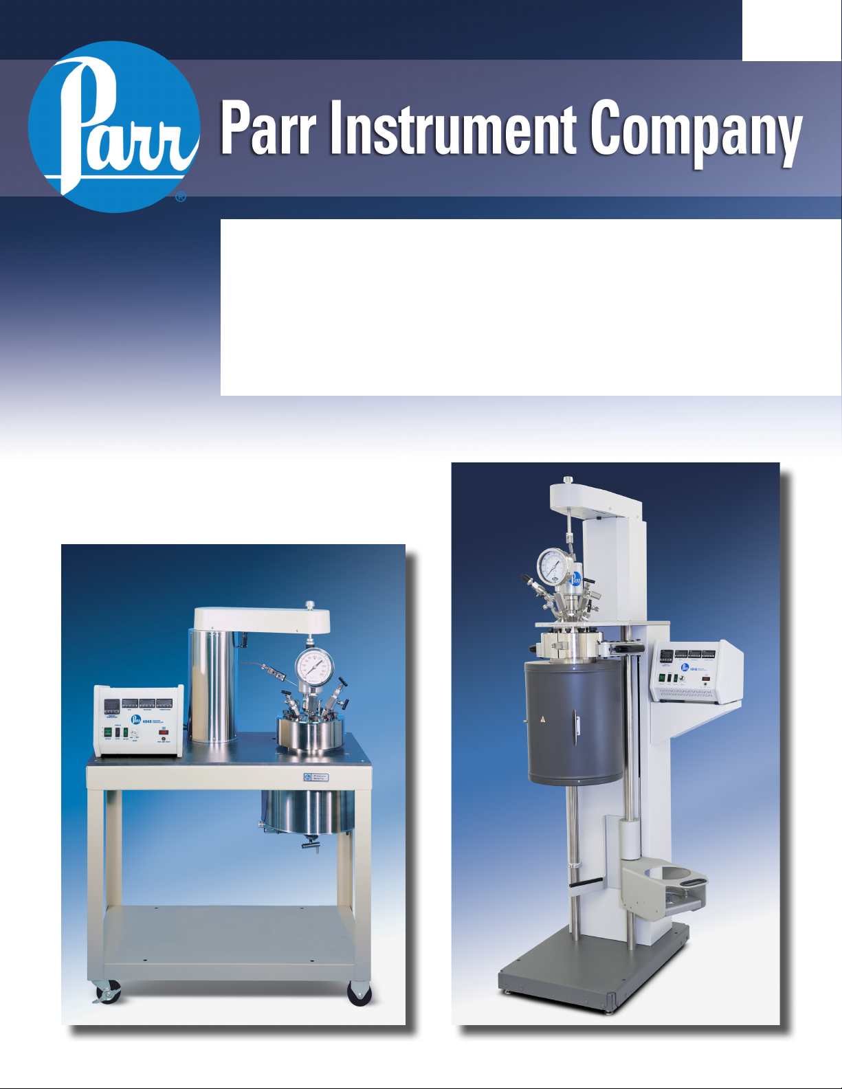
4550
Floor Stand Reactors
Operating Instruction Manual
395M
Page 2

Floor Stand Reactors
PREFACE 3
Scope 3
Related Instructions 3
Intended Usage 3
Safety Information 3
General Specifications 3
Explanation of Symbols 4
Environmental Conditions 4
Unpack Carefully 4
Provisions for Lifting and Carrying 4
Cleaning & Maintenance 4
User’s Responsibility 5
Fixed Head or Removable Head Design 6
Fixed Head or Removable Head Vessel Design 6
Flat PTFE Gasket or Self Sealing O-ring Closure 6
INSTALLATION 7
Pressure and Temperature Limits 7
Assemble the Reactor 8
HOW TO USE THE VESSEL 14
Fixed Head Vessels 14
To open the Vessel 14
Before Closing the Vessel 14
To Close the Vessel 14
Removable Head Vessels 14
To Open the Vessel 14
Before Closing the Vessel 14
To Close the Vessel 14
Sealing Vessels with PTFE Gaskets 14
Gas Connections 14
Pressurizing the Vessel 15
Do Not Overfill the Vessel 15
Releasing Pressure 15
Withdrawing Liquid Samples 15
Initial Operating Test 15
MAINTENANCE 16
General Maintenance Notes 16
Periodic Pressure Tests 17
IDENTIFY THE VALVES 10
Gas Inlet Valve 10
Gas Release Valve 10
Liquid Sampling Valve 10
OTHER VESSEL HEAD FITTINGS 11
Safety Rupture Disc 11
Type J Thermocouple 11
Pressure Gage 11
Gage and Valve Adapters 11
ACCESSORIES 12
Internal Cooling Coils 12
Variable Speed Electric Motor 12
Air Motor 12
Liners 12
Spare Parts Kit 12
Pneumatic Lift for Fixed Head Vessels 13
PARTS LISTS 18
Reaction Vessel Parts List 18
Overarm Parts List 21
Cooling Coil Parts List 22
Heaters Parts List 23
DRAWINGS 24
4553 - 1 Gallon Fixed Head Stand Assembly 24
4554 - 2 Gallon Fixed Head Stand Assembly 26
Customer Service
Questions concerning the installation or operation
of this instrument can be answered by the Parr
Customer Service Department:
1-309-762-7716 • 1-800-872-7720
Fax: 1-309-762-9453
E-mail: parr@parrinst.com
http://www.parrinst.com
2
Parr Instrument Company
Page 3

4550 Floor Stand Reactors
PREFACE
Scope
These instructions describe the installation, operation and maintenance of Parr Series 4550 Floor
Stand Reactors offered in two sizes, 1 and 2 Gallon
(3.75 and 7.5 liter). They cover the basic steps to
be followed when installing these reactors and
describe the function of all standard components.
They are intended to be used in conjunction with
several related instruction sheets listed on the
previous page. This information describes several
components that are common to most Parr pressure
reaction equipment, and includes safety precautions and other related information applicable to all
reaction laboratories. The users should study all of
these instructions carefully before starting to use
these vessels so that they will fully understand the
capabilities and limitations of the equipment.
Related Instructions
The following Parr publications are also included to
further your understanding of this instrument and
its component parts:
No. Description
201M Limited Warranty
230M Safety Precautions to be observed when
operating Pressure Reaction Equipment
231M Operating Instructions for Parr Safety
Rupture Discs
234M Operating and Maintenance Instructions
for Parr Magnetic Drives
323M Operating Instructions for Parr Pressure
Relief Valves
548M Operating Instructions for 4848 Reactor
Controllers
FX004 Health & Safety Assurance Certification
Safety Information
To avoid electrical shock, always:
1. Use a properly grounded electrical outlet of
correct voltage and current handling capability.
2. Ensure that the equipment is connected to
electrical service according to local national
electrical codes. Failure to properly connect may
create a fire or shock hazard.
3. For continued protection against possible
hazard, replace fuses with same type and rating
of fuse.
4. Disconnect from the power supply before
maintenance or servicing.
To avoid personal injury:
1. Do not use in the presence of flammable or
combustible materials; fire or explosion may
result. This device contains components which
may ignite such material.
2. Refer servicing to qualified personnel.
General Specifications
Electrical Ratings
Controller ratings are found in the Operating
Instructions for the controller supplied with your
reactor and on the controller data plate.
Before connecting a controller to an electrical outlet,
the user must be certain that the electrical outlet has
an earth ground connection and that the line, load
and other characteristics of the installation do not
exceed the following limits:
Voltage: Fluctuations in the line voltage should not
exceed 10% of the rated nominal voltage shown on
the data plate.
Frequency: Controllers can be operated from either
a 50 or 60 Hertz power supply without affecting their
operation or calibration.
Intended Usage
This system has been designed for use as a high
pressure reactor system. It has been designed, built,
and tested to strict physical and electrical standards.
However, it is the user’s responsibility to install and
operate it in conformance with local pressure and
electrical codes.
If this equipment is used in a manner beyond its
intended usage, the protection provided by the
equipment may be impaired.
Current: The total current drawn should not exceed
the rating shown on the data plate on the controller
by more than 10 percent.
Thermocouple: Unless otherwise specified, all
Series 4848 Reactor Controllers operate with a
Type J (iron-constantan) thermocouple. The total
resistance of the thermocouple and the lead wires
should not exceed 100 ohms. If the resistance of
the thermocouple circuit is higher, it will reduce the
sensitivity of the control system.
www.parrinst.com
3
Page 4
4550 Floor Stand Reactors
Explanation of Symbols
II On position, full power heater switch
I On position, half power heater switch
O Off Position
~ Alternating Current (AC)
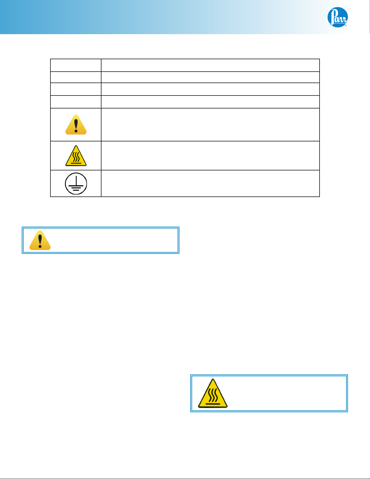
This CAUTION symbol may be present on the Product Instrumentation
and literature. If present on the product, the user must consult the appropriate part of the accompanying product literature for more information.
This CAUTION symbol indicates that the surface may be hot.
Protective Earth (PE) terminal. Provided for connection of the Protective Earth (green or green/yellow) supply system conductor.
Environmental Conditions
This instrument is intended to be used indoors.
Caution!
Do not use in hazardous atmospheres.
Operating: 15 ºC to 35 ºC; maximum relative humidity of 80% non-condensing. Installation Category II
(over voltage) in accordance with IEC 664.
Pollution degree 2 in accordance with IEC 664.
Altitude Limit: 0 to 2000 meters above sea level.
Storage: -25 °C and 65 °C; 10% to 85% relative
humidity.
Unpack Carefully
Unpack the equipment carefully and check all the
parts against the packing list. If shipping damage is
discovered, report it immediately to the delivering
carriers. The vessel, motor, heater, and temperature
controller may be packed separately for convenience
in shipping, but these parts are easily reassembled.
Examine the components closely for any loose parts
or shipping damage and be sure to check all layers of
packing materials thoroughly so as not to overlook
any parts which might otherwise be discarded.
Provisions for Lifting and Carrying
The 4550 Floor Stand Reactor and its components
are very heavy. Before moving ensure all cables are
disconnected. Use proper and safe lifting techniques
when installing or moving the 4550 Reactor and/ or
its components.
Cleaning & Maintenance
Periodic cleaning may be performed on the exterior
surfaces of the instrument with a lightly dampened
cloth containing mild soap solution. All power should
be disconnected when cleaning the instrument.
There are no user serviceable parts inside the product other than what is specifically called out and
discussed in this manual. Advanced troubleshooting
instructions beyond the scope of this manual can
be obtained by calling Parr Instrument Company in
order to determine which part(s) may be replaced or
serviced.
Ensure that any hot surfaces have had
adequate time to cool before cleaning
or maintaining the reactor and/or its
components.
4
Parr Instrument Company
Page 5

4550 Floor Stand Reactors
User’s Responsibility
All Parr Reactors and pressure vessels are designed and manufactured with great care to assure safe operation when used within their prescribed temperature and pressure limits. But . . . the basic responsibility for
safety when using this equipment rests entirely with the user; who must:
1. Select a reactor or pressure vessel which has the
capability, pressure rating, corrosion resistance
and design features that are suitable for its intended use. Parr engineers will be glad to discuss available equipment and material options
with prospective users, but the final responsibility for selecting a reactor or pressure vessel
that will perform to the user’s satisfaction in any
particular reaction or test must rest with the user
– not with Parr.
In exercising the responsibility for the selection
of pressure equipment, the prospective user
is often faced with a choice between over- or
under-designed equipment. The hazards introduced by under-designed pressure vessels are
readily apparent, but the penalties that must
be paid for over-designed apparatus are often
overlooked.
Recognizing these criteria, Parr reactors and
pressure vessels are offered in several different
styles, each designed for convenient use in daily
operation within certain temperature and pressure limits, using gaskets, closures and other
elements carefully selected for safe operation
within the limits specified for that design. But in
order to preserve the validity of these designs,
all temperature and pressure limits must be
observed, and no attempt should be made to
increase these limits by making alterations or by
substituting components which are not recommended by Parr Instrument Company.
2. Install and operate the equipment within a
suitable barricade, if required, with appropriate
safety accessories and in full compliance with
local safety codes and rules.
All standard Parr pressure vessels are provided
with either a suitable relief device or a means
to attach one (typically in the form of a plugged
opening). When a pressure vessel is delivered
without a pressure venting device, it is the customer’s responsibility to provide pressure relief
in order to protect the operator and the equipment from destructive high pressures. If you
need more information or need help in selecting
a proper relief device, please contact Parr Instrument Company.
3. Establish training procedures to ensure that any
person handling the equipment knows how to
use it properly.
4. Maintain the equipment in good condition and
establish procedures for periodic testing to be
sure the vessel remains structurally sound.
www.parrinst.com
5
Page 6
4550 Floor Stand Reactors
Fixed Head or Removable Head Design
Parr Series 4550 Series Reactors are furnished with two structural options in addition to the size, pressure
range, stirrer motor, controller and similar options. These are:
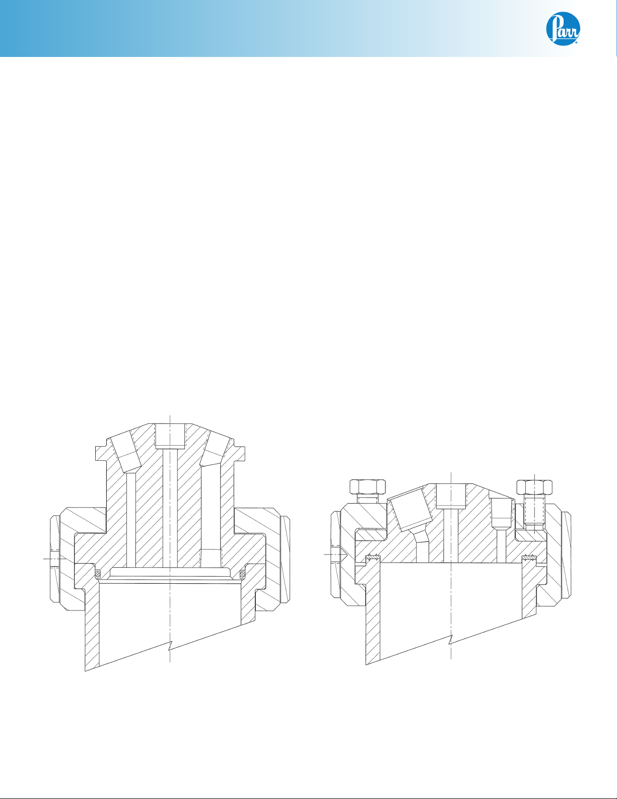
Fixed Head or Removable Head Vessel Design
In the fixed head design, the head of the vessel
may remain fixed in the reactor support stand. All
attachments to the head, gas and liquid feed and
discharge lines, cooling water, vapor take-off and
condenser, thermocouple, and any electrical leads
can remain permanently in place. The reactor is
opened by removing the cover clamp sections and
lowering the cylinder away from the head.
In the removable vessel design, the entire vessel
must be removed from the support stand for charging, product recovery, and cleaning.
There is no difference in the pressure or temperature
limits or basic operating instructions based upon the
fixed head or movable vessel options. There are differences in the design of the stand components which
adapt the vessels to the support system.
Flat PTFE Gasket or Self Sealing O-ring Closure
The flat gasket is held in a recess in the vessel head
and a machine pilot on the cylinder closes the recess
to completely contain the gasket. The split ring closure
used with this gasket has six cap screws which must be
tightened to develop the loading on the gasket.
The self sealing design features an O-ring retained in
a groove on the vessel head. This design is self sealing and the split ring used with this sealing system
does not require nor have the cap screws used with
the flat gasket.
Maximum temperatures of a given system are dependant upon the material of construction and type
of seal. Other accessories may limit operating temperature. The flat PTFE gasket can be used to operating temperatures as high as 350 °C. The flat flexible
graphite gasket can be used to operating temperatures
as high as 500 °C. The maximum temperature of the
vessels equipped with O-ring seals depends upon
the material used for the O-ring. The most common
material is a fluoroelastomer (FKM) which has a 225 °C
maximum operating temperature limit.
Fixed Head with O-ring
6
Parr Instrument Company
Moveable Head with Flat Gasket
Page 7

INSTALLATION
Pressure and Temperature Limits
4550 Floor Stand Reactors
The working pressure and temperature at which any
reactor or pressure vessel can be used will depend
upon the design of the vessel and the materials
used in its construction. Since all materials lose
strength at elevated temperatures, any pressure
rating must be stated in terms of the temperature at
which it applies. The standard material of construction for Parr Instrument Company is Type 316 Stainless Steel.
Limits for vessels made of other materials and for
other operating temperatures can be obtained from
Parr Customer Service. No attempt should be made
to increase these limits by making alterations or by
substituting components that are not recommended
by the Parr Instrument Company. It must also be
understood that lower pressure and temperature
limits may be required for modified reactors and for
vessels made of special alloys.
Limits for vessels will be determined by the physical characteristics of the vessel material and will be
prescribed on an individual basis.
The maximum working pressure and temperature
for any vessel is governed by the design of the
vessel and the strength of the material from which
it is constructed. There is also a close relationship
between working pressure and temperature since
the strength of any material will normally fall off
as the temperature is increased. Temperature and
pressure limits are also affected by the physical
properties and temperature limits of the gaskets and
seals used in the vessel, and by any valves, gages
or other fittings attached to the vessel. Obviously,
the safe operating pressure of any system can be no
higher than that of its lowest rated component.
All Parr reactors show the maximum safe operating
pressure and temperature imprinted on the cylinder.
The working pressure and temperature in these one and two gallon reactors must not exceed the
following maximum limits:
Pressure Vessel and Temperature Limits
Vessel Material Maximum Pressure Maximum Temperature
T316SS 1900 psig 350 °C PTFE Flat Gasket
T316SS 1900 psig 300 °C FFKM O-ring
T316SS 1900 psig 225 °C FKM O-ring
www.parrinst.com
7
Page 8

4550 Floor Stand Reactors
Assemble the Reactor
These reactors require at least 10 sq. ft. of workspace in a well-ventilated area with convenient
access to an electric outlet, running water, air and a
drain. This unit needs to be placed at least 10 inches
away from walls or flammable materials.
1. Set the stand in the workspace.
2A. Removable Vessels.
First pivot the overarm assembly to the back of
the support stand.
The pressure vessel has been shipped as a
complete assembly; it may be easiest on the
initial setup to place the entire pressure vessel
assembly into the heater. Note: The complete
assembly does not need to be removed from the
heater during opening and closing operations.
It is designed so that the cylinder can remain
in the heater while the head and split rings are
attached or removed.
Once the vessel assembly is in place rotate the
magnetic stirrer by hand to make sure that it
turns freely. Then move the overarm back into
position above the vessel. The knob on the top
of the overarm will raise the upper shaft with
coupling for attachment to the adapter on the
top of the magnetic stirrer. Push down and
rotate the upper shaft to bring these components into alignment.
Occasionally the motor housing and overarm assembly may vibrate out of the standard position.
If the upper shaft is not in alignment with the
center of the top of the magnetic stirrer it will be
necessary to loosen the bolt which attaches the
motor housing to the support stand. Remove
the motor housing panel; there is a single bolt
that runs through the lower housing support
and the top shelf of the floor stand. Once the
bolt is loosened, rotate the housing the required
amount, connect the upper shaft to the magnetic
stirrer and then tighten the motor housing bolt.
2B. Fixed Head Reactor.
Bolt the stand to the floor using the
holes in the base plate.
Loosen the panel screw of the vessel retainer
mounted on the midplate of the support stand
and open the retainer bracket.
The pressure vessel has been shipped as a
complete assembly. It is necessary to loosen the
split ring bolts and remove the split ring. Lift the
head assembly out of the cylinder and slide it
into the midplate of the stand. Close the retainer
bracket. The cylinder should be placed in the
cylinder lift bracket.
Rotate the magnetic stirrer by hand to make sure
that it turns freely.
Connect an air line to the 1/4” quick disconnect
fitting at the base of the support stand. This
pneumatic lift package will raise or lower the
cylinder. It may also be used for the heater. The
lever on the side panel of the support frame
controls the lift motion.
The pneumatic package includes a pressure
regulator with gage located inside of the support
stand housing. It can be accessed by removing
the back panel of the support stand. The regulator has been preset to 50 psi. The regulator can
be adjusted by lifting up on the cap. Rotate
clockwise to increase pressure, counter-clockwise to decrease the amount of pressure sent to
the pneumatic lift cylinder. Press the cap back
down after setting the pressure.
The flow control valves have been preset for
optimum performance. Both the speed and
lifting capacity of the pneumatic lift package can
be adjusted with the flow control valves located
on the input and output ports of the pneumatic
cylinder.
8
Parr Instrument Company
Page 9

4550 Floor Stand Reactors
3. Set the Reactor Controller near the reactor, leaving a space of at least six inches between the
controller and the base of the reactor so that the
controller will not be unduly affected by radiant
heat. Connect the reactor to the controller using
information contained in its Instruction Manual
548M or follow the steps below.
Labeled connections are provided on the rear
panel of the controller.
Parr Cooling Only:
The Parr Cooling output connector is to be used
only with Parr Instrument Company cooling solenoid valve assemblies supplied with the appropriate cooling power cord.
Parr Heating Only:
5. Plug the motor cord into the motor socket on the
rear of the controller.
Secure the clamp on the motor cord
with the provided screw next to the
motor socket for safety purposes.
6. Connect the thermocouple and extension wire
to both the thermocouple and to the controller
in the “Primary Temp Input” position on the rear
panel. Insert the thermocouple in the thermowell.
7. Connect leads from accessory packages such as
tachometer, pressure transducer and high temp
cut-off to the designated positions on the back
panel of the 4848 Controller.
8. Connect cooling water to the magnetic drive.
See Instruction Manual No. 234M.
9. Connect tubing to the rupture disc outlet and run
to a safely vented area. See Instruction Manual
231M.
The Parr Heating output connector is to be used
only with Parr Instrument Company heater assemblies supplied with the appropriate heater
power cord.
Note: Do not make connections to a Variac,
Powerstat or the like to attempt to control the
heating output. The heavy inductive load on
the primary side of such devices can destroy
the internal solid state relay located in the
4848 Controller.
Parr Motor Only:
The Motor output connector is to be used only
with Parr Instrument Company motor assemblies
supplied with the appropriate motor power cord.
4. Connect the heater cord from the heater into
the heater socket on the rear panel of the Series
4848 Reactor Controller.
10. Note the voltage and amperage requirement
stamped on the controller data plate, and then
plug the power cord into an appropriate outlet.
Power for these reactors should be drawn from
a grounded outlet capable of carrying up to the
full current rating of the reactor.
11. If an electric stirrer motor is supplied, turn the
speed control knob fully counterclockwise on
the Reactor Controller, turn on the motor switch
and slightly increase the speed for a short run
to check the stirrer drive system but do not turn
on the heater, put heater toggle switch in center
position (OFF). There must always be a vessel in
the heater when it is turned on, and the vessel
and heater sizes must match. If the heater is operated without proper size vessel in contact with
the mantle, the mantle may overheat and fail.
www.parrinst.com
9
Page 10

4550 Floor Stand Reactors
IDENTIFY THE VALVES
Gas Inlet Valve
The gas inlet valve is easily identified when the bomb
is open by noting that it is connected to a dip tube
that extends to a point near the bottom of the bomb
cylinder. This is an angle valve with an attached fitting
which provides a socket for attaching the A495HC
pressure hose furnished with the reactor.
Gas Release Valve
The gas release valve is connected to an opening
that will not have any fitting installed on the underside of the head. Gas released from this valve
will be drawn from the top of the reactor. The gas
release port does include a 1/8th NPT thread on the
PRESSURE GAGE
underside of the head where an additional dip tube
or catalyst addition device may be added. If one of
these additions is made to this port then an additional valve must be added to the gage adapter to
be used as a gas release valve.
Liquid Sampling Valve
The liquid sampling valve is attached to the same
fitting as the gas inlet valve and connected to the
same dip tube. With this arrangement, incoming gas
is always introduced below the surface of the liquid
and the operator is provided with a means for clearing
the dip tube to be sure that any sample taken during
a run will be representative of the charge. This can be
done by opening the gas valve momentarily to force
any liquid in the dip tube back into the reactor before
withdrawing a sample from the sampling valve.
MAGNETIC DRIVE ASSY
HEX PLUG (EXTRA PORT)
(2) ELBOW,COOLING COIL
(INLET/OUTLET)
GAS RELEASE VALVE
RUPTURE DISC ASSY
VALVE ADAPTER
COMPRESSION RING
ADAPTER BUSHING
HEAD, REMOVABLE
(2) MALE CONNECTOR
(COOLING COIL)
STIRRER SHAFT ASSY
THERMOWELL
SERPENTINE COOLING COIL
THERMOCOUPLE
GAS INLET VALVE
ADAPTER, GAS CONNECTION
VALVE ADAPTER
VALVE, LIQUID SAMPLING
GAGE ADAPTER
ADAPTER BUSHING
GLAND NUT, MAG DRIVE
MALE CONNECTOR, DIP TUBE
DIP TUBE
10
(2) IMPELLER ASSY
STIRRER BRACKET ASSY
Parr Instrument Company
Page 11

4550 Floor Stand Reactors
INLET SAMPLING VALVE
OTHER VESSEL HEAD FITTINGS
Safety Rupture Disc
There is a safety rupture disc attached to the head that
is intended to rupture and release the pressure before
it reaches a dangerous level. A metal tag wired to
the safety head identifies the burst pressure at room
temperature for that particular disc. A similar tag is
furnished with each replacement disc. This tag must
remain with the apparatus at all times so that both present and future operators will be aware of the disc rating.
Users should read the discussion of rupture discs given
in the Instruction Sheet No. 231M for a complete description of the characteristics of rupture discs and the
precautions to be observed when operating pressure
equipment protected by this type of safety device.
A typical pre-bulged disc can be used to 90% of the
rating on the tag. For additional protection, the user
should install an adequate and safe venting system for
removing any toxic, flammable or volatile material which
would be released if the rupture disc should burst. A
connector for attaching 3/8” OD tubing to the discharge
port of the rupture disc is provided for this purpose.
Type J Thermocouple
A Type J thermocouple in a 1/8” dia. stainless steel
sheath is furnished with the reactor. Insert this thermocouple into the head thermowell and connect
it to the thermocouple socket on the rear panel of
the temperature controller using the extension wire
furnished with the reactor.
Pressure Gage
The pressure gage furnished with this reactor has a T316
Stainless Steel Bourdon tube. Gages are furnished in
a variety of ranges to meet individual needs. Typically,
the gage and the rupture disc are furnished as matched
ranges. For applications where a gage is selected with
a range under 1000 psi, a relief valve is added and set
to protect the gage. A 1000 psi rupture disc is installed
as the fail-safe vessel protection.
For highly corrosive applications where the vapor
phase might corrode the stainless Bourdon tube, Parr
offers isolator assemblies in a variety of materials.
These isolators with their internal piston isolate the
vapors from the gage.
The gage adapter includes a ¼” NPT side port with a
plug installed. This position may be used for a variety
of fittings such as a needle valve, pressure transducer
or relief valve.
Gage and Valve Adapters
The pressure gage and the combined gas inlet and
sampling valves are attached to the head with an
adapter which allows these fittings to be drawn up
tightly when facing in any direction. To attach these
fittings to the head, screw the gage or valves firmly
into the adapter, then run the 209HC4 bushing onto the
threaded stem as far as it will go. Screw this assembly
into the head until the nose of the adapter is seated;
then back it off until the valve or gage is facing in the
desired direction. Now hold the fitting firmly in place
and close the joint by tightening the 209HC4 bushing.
This connection can be made and broken repeatedly
without destroying the sealing faces. A light coating of
thread lubricant, such as Parr No. 424HC2 High Temperature Anti-Seize Lube, applied to the threads and to
the nose of the adapter will help to obtain a tight joint.
Note: Do not use PTFE tape on the straight thread
connections of the coned adapters and mating
bushings. PTFE tape should only be used on the (NPT)
threads such as the needle valves or gage connection.
56HC
208HC15
209HC4
PRESSURE GAGE
420HC2
A129VB
A131VB
208HC6
209HC4
GAS RELEASE VALVE
www.parrinst.com
A130VB
658HC
11
Page 12

4550 Floor Stand Reactors
ACCESSORIES
Internal Cooling Coils
Cooling coils can be installed in any of these reactors. Reactors purchased without a coil can have this
feature added.
Standard cooling coils are made in serpentine
configurations. A serpentine coil offers a smaller
but effective cooling area and it does not interfere
with the use of a liner. An optional spiral coil can
be provided, which offers more surface area than a
serpentine coil but it is more difficult to clean and,
when installed, it prevents the use of some internals
and liners. Plugs are available to seal the cooling
coil opening when the coil is not used.
Variable Speed Electric Motor
Reactors are normally equipped with a DC variable
speed motor supplied and controlled through the
Series 4848 Reactor Controller. Instructions for connecting and operating these motors are included in
the controller instruction sheet No. 548M. This motor
is usually installed in a drive system designed to
produce stirring speeds from 0 to 600 rpm. Higher
speeds (1000 or 1700 rpm) can be obtained by
substituting larger diameter motor drive pulleys.
Air Motor
directions for a few minutes; then connect the air
line and run the motor until there is no further
trace of solvent in the exhaust. If the muffler felts
are dirty, wash them in solvent or replace them.
Re-lubricate the motor with a squirt of oil into the
chamber and reassemble. If it becomes necessary to
disassemble the motor to replace the vanes, follow
directions given in the instruction sheet published
by the Gast Manufacturing Corp., Benton Harbor,
Michigan.
Liners
Glass or PTFE liners can be furnished to fit most
Parr reactors. These liners slide into the cylinder.
Although they will not keep corrosive vapors from
reaching the surfaces of the cylinder and head, they
make it much easier to add and remove liquid reactants, and they give some protection to the cylinder
when working with corrosive solutions. It must be
noted, however, that adding a liner will slow the
heat transfer rate into the vessel, and it may be
necessary to adjust the temperature control method
to prevent overheating.
Liner Part Numbers
Fits
ID
6 inches 1 Gallon 894HC 894HC4HA
6 inches 2 Gallon 894HC2 894HC5HA
Cylinder
Size
Glass
Liner
PTFE
Liner
Variable stirring speeds from 100 to 2000 rpm can
be obtained by replacing the standard motor with
an A1393HC air motor. This motor operates on
compressed air, which must be supplied at 40 psig
minimum pressure with at least 10CFM available at
that pressure. It is furnished with a speed control
valve and oiler.
To operate reactors equipped with an air motor, connect the air hose to a compressed air line. Fill the
oiler with SAE 10 oil and adjust the oiler to feed one
drop per minute into the air stream. For long continuous runs at high speeds, the oiling rate should
be increased to three drops per minute. If the motor
becomes sluggish, flush it with a non-flammable
solvent in a well-ventilated area. Disconnect the air
line and muffler and pour a small amount of solvent
into the inlet port. Rotate the shaft by hand in both
Spare Parts Kit
Parr can furnish spare parts kits for these reactors
which will provide a reserve supply of parts and
tools sufficient to handle most normal replacements
and emergency repairs during a year of heavy
usage.
These kits contain replacement gaskets, packing,
O-rings, shafts, bearings, and rupture discs. They
can be ordered from any Parr Dealer or direct from
the Parr Instrument Company. The order must
specify the reactor size and indicate type of rupture
disc, stirrer drive and whether it has a flat-gasket
or O-ring seal. Always provide the reactor serial
number (stamped on head and cylinder) to assure
receipt of proper replacement parts.
12
Parr Instrument Company
Page 13

Pneumatic Lift for Fixed Head Vessels
For those models equipped with a
pneumatic lift package, the following
instructions apply:
This pressure reactor assembly uses
an A2760HC Pneumatic Lift Package
to raise and lower the Cylinder. If
needed, It can also be used to raise
and lower the Heater assembly.
4550 Floor Stand Reactors
Technical Support
Contact our customer service
department with questions
concerning the Pneumatic Lift
Package.
Toll Free: 1(800) 872-7720
E-mail: parr@parrinst.com
Hand Lever Valve Assembly “Joystick”
Lift up on joystick to go “UP” or
Push down on joystick to go “DOWN”.
Cylinder Lift Assembly
Pneumatic Lift Cylinder
Pressure Regulator Cap
Pressure Regulator with Gage
The air pressure has been preset
to 50 psi. The regulator can be
adjusted by lifting up on this cap
and then turning “clockwise” to
increase or “counterclockwise”
to decrease the amount of
pressure being sent to the
pneumatic cylinder.
Press cap back down after setting
pressure, this will prevent the
cap from being unintentionally
turned.
Heater Assembly
Hose Bulkhead Flow Control Connector
A (1/4”) quick disconnect fitting has been
provided for the air line connection.
User is responsible for connecting to their
air supply.
Hose Coupler
Flow Control Valves
The flow control valves have been preset for optimum
performance. Both the speed and lifting capacity of the
Pneumatic lift package can be adjusted with the flow
control valves located on the input and output ports of
the pneumatic cylinder.
www.parrinst.com
13
Page 14

4550 Floor Stand Reactors
HOW TO USE THE VESSEL
Fixed Head Vessels
First, lower the heater and push it aside before
attempting to remove the split ring and cylinder.
Raise the cylinder support holder to the bottom of
the cylinder. Open the gas release valve to discharge
any internal pressure.
To open the Vessel
Remove the split rings. For vessels with a confined,
flat PTFE gasket, loosen the six bolts. For vessels
with an O-ring closure, loosen the latches on each
side of the split rings. The split ring halves can now
be removed. The head with all attached fittings will
remain in place. The cylinder can now be lowered
away. Handle the cylinder carefully so as not to
damage the stirring shaft and other internals.
Before Closing the Vessel
Examine the head seal carefully to be sure that
it is in good condition. The seal should not have
any nicks or be hardened, discolored or deformed.
Examine the mating surfaces on the cylinder and
head to be sure they are clean and free from burrs;
then raise the cylinder up to the head.
To Close the Vessel
Put the two split ring halves around the head and
cylinder flanges and fasten the latches or tighten the
bolts as assembled before.
Removable Head Vessels
First, open the gas release valve to discharge any
internal pressure. For vessels on a movable floor
cart, lift the vessel out of the heater before attempting to remove the split ring and head. For vessels
on a stationary stand, loosen the panel screw holding the vessel retainer, remove the vessel from the
stand and set it on a table.
To Open the Vessel
Remove the split rings. For vessels with a confined,
flat PTFE gasket, loosen the six bolts. For vessels
with an O-ring closure, loosen the latches on each
side of the split rings. The split ring halves can now
be removed. The head with all attached fittings is
free to be lifted from the cylinder. Handle the head
carefully so as not to damage the stirring shaft and
other internals.
Before Closing the Vessel
Examine the head seal carefully to be sure that
it is in good condition. The seal should not have
any nicks or be hardened, discolored or deformed.
Examine the mating surfaces on the cylinder and
head to be sure they are clean and free from burrs.
Then carefully set head on cylinder.
To Close the Vessel
Slide the two split ring halves around the cylinder
and head flanges. If equipped with a drop band,
position the split ring halves such that the indentation for one of the halves is located 180 degrees
away from the pressure gage. Slide the drop band
over the split ring halves and tighten the set screw
lightly to hold the band in place.
For vessels on a movable floor cart, place the vessel
into the heater with the gage facing forward and
swing the drive arm into position, connecting the
rubber sleeve onto the spline coupling on the stirrer.
For vessels on a stationary stand, place the vessel
onto the midplate such that the drop band set screw
fits into the slot on the back of the midplate.
Note: The following steps are common
to both head configurations
Sealing Vessels with PTFE Gaskets
If your split ring has compression bolts, tighten each
of the bolts with the wrench furnished. Apply a firm
but hard pull to each bolt. Or, if a torque wrench
is available, apply 25ft-lbs to each bolt. Tightening
should proceed in a criss-cross pattern rather than
progressively around the circle. Let the vessel stand
for about five minutes after the initial tightening;
then tighten the bolts again. This will compensate
for any tendency of the PTFE gasket to flow under
the loading pressure.
Gas Connections
Gas connections are dependent on applications.
For general usage, use the pressure hose furnished
with the reactor. Screw the Type “A” coned pressure
fitting into the adapter attached to the gas inlet valve
and tighten the compression nut firmly. Do not use
any thread dope on the coned fitting. The A495HC
pressure hose is made of reinforced Nylon that can
be used at ambient temperature for all non-corrosive gases at pressures up to 2500 psig. For operations involving corrosive gases, this hose should
14
Parr Instrument Company
Page 15

4550 Floor Stand Reactors
be replaced with an A490HC hose which has a PTFE
lining and a braided stainless steel outer covering.
Both of these hoses have the same fittings. The
A506HC all metal hose is also available in stainless
steel and other corrosion resistant materials.
Pressurizing the Vessel
Check all valves carefully before admitting gas into
the system. The liquid sampling valve must remain
closed throughout the charging procedure. The gas
release valve must also be closed unless the vessel
is to be purged, or unless there is to be a continuous
flow through the reactor during a run. Always make
certain that the pressure in the gas tank is greater
than the pressure in the vessel; otherwise liquid
will be forced out of the vessel and into the gas
tank when the inlet valve is opened. If there is any
possibility that the tank pressure might not be high
enough to force gas into the reactor, install a oneway check valve (optional) in the gas line to prevent
any reverse flow. After the desired pressure has
been reached, close the valves and disconnect the
hose at the vessel end.
Alternate gas hoses with check valves are available
from Parr upon request.
Do Not Overfill the Vessel
Always watch the pressure gage closely when admitting gas so as not to exceed the maximum working limit. Remember that any subsequent increase
in temperature will raise the pressure. Also, be
sure that the amount of liquid placed in the vessel
is carefully controlled. As a general rule, the liquid
charge should not exceed two-thirds of the capacity
of the cylinder. Too much liquid in the vessel can
lead to development of dangerous pressures if sufficient space is not provided for expansion when the
liquid is heated. This hazard is explained in greater
detail in a warning statement included in the Safety
Instruction Manual No. 230M.
Withdrawing Liquid Samples
Liquid samples may be withdrawn from the sampling valve attached to the same adapter as the
gas inlet valve whenever the vessel is pressurized.
Always close the inlet valve before withdrawing a liquid sample and open the sampling valve
cautiously because liquid will be discharged with
considerable force. Be particularly careful if the
temperature of the sample is above its boiling point
at atmospheric pressure. If so, it will “flash” and be
lost as soon as it is released from the vessel. This
problem can be avoided by connecting an optional
4352 Sample Collection Vessel to the sampling valve
to collect the liquid into an appropriate receiver. The
addition of a small amount of gas can be used to
clear the dip tube between liquid samples so that
the next sample drawn through the tube will truly
be representative of the mixture..
Initial Operating Test
Read all operating instructions carefully so as to be
well acquainted with the correct procedures for handling the vessel and for operating the controller and
other accessories. An initial operating test should
be made, with only water, to check the apparatus
before starting the first experimental runs. For this
initial test, fill the cylinder not more than half full of
water and run the temperature up to 150 ºC while
checking the apparatus for leaks and observing the
performance of the temperature controller.
Releasing Pressure
Use the gas release valve to reduce the pressure in
the vessel if the reactor is accidentally overcharged
when filling. Use this valve also to release any
excess pressure during a run and to exhaust the
vessel at the end of a run. If the discharge gases are
flammable or toxic, discharge to an exhaust hood or
to any other safe release point.
www.parrinst.com
15
Page 16

4550 Floor Stand Reactors
MAINTENANCE
General Maintenance Notes
1. Periodically inspect all electrical wiring and pressure connections for excessive corrosion. Suspect parts should be replaced by components
only supplied by Parr Instrument Company.
2. Always use appropriate wrenches on all fittings
and valves. Never use pliers or pipe wrenches.
3. Head and cylinder service fixtures are available
for convenience and protection of components
during maintenance of your reactor.
4. To reinstall straight thread (NPS) fittings to the
head, screw the gage or valves firmly into the
adapter.
Run the bushing onto the threaded stem as far
as it will go. Screw this assembly into the head
until the nose of the adapter is seated; then
back it off until the valve or gage is facing in the
desired direction (no more than one full turn).
Hold the fitting firmly in place and close the
joint by tightening the bushing. This connection
can be made and broken repeatedly without
destroying the sealing surfaces. A light coating
of thread lubricant, such as Parr High Temperature Anti-Seize Lubricant, applied to the straight
threads and to the nose of the adapter will help
to obtain a tight joint.
Note: PTFE tape should not be used on this
joint.
5. NPT (National Pipe Taper) threads should not
be disassembled any more than necessary. It
will become increasingly difficult to maintain a
tight seal with these tapered threads if the joint
is made and broken repeatedly. Grafoil tape or
PTFE tape (if temp allows) should be used on all
NPT threads.
7. If your vessel is equipped with a loose compression ring be sure that it is in place on the head
before attaching any head fittings. The compression ring cannot be installed after fittings have
been screwed into the head.
8. Clean all threads and gas passages thoroughly
and remove all tape fragments when overhauling a vessel. An ultrasonic bath is excellent for
cleaning metal parts, but do not place a thermocouple probe, pressure gage, face seals or ball
bearings in an ultrasonic bath. Periodic cleaning
may be performed on the exterior surfaces of
the reactor stand with a lightly dampened cloth
containing mild soap solution. All power should
be disconnected when cleaning.
9. Routinely inspect compression bolts on split ring
closure for lubrication and cleanliness. These
screws should not be allowed to dry because
the threads will seize. Regularly apply Parr
High Temperature Anti-Seize Lubricant (Parr No.
424HC2) before this happens.
10. To operate reactors equipped with an air motor,
connect the air hose to a compressed air line.
For best torque and speed control the piping to
the motor should be at least 3/8” IPS or larger.
Fill the oiler with SAE 10 oil and adjust the oiler
feed one drop per minute into the air stream.
For long continuous runs at high speeds, the oiling rate should be increased to three drops per
minute. If the motor becomes sluggish, flush
it with a non-flammable solvent in a well ventilated area.
Disconnect the air line and muffler and pour
a small amount of solvent into the inlet port.
Rotate the shaft by hand in both directions for
a few minutes; then connect the air line and
run the motor until there is not further trace of
solvent in the exhaust. If the muffler is dirty,
replace it. Relubricate the motor with a squirt of
oil into the chamber and reassemble.
6. Do not use oil or anti-seize lubricant on threads
or fittings if the vessel is to be used with oxygen.
16
Parr Instrument Company
11. If servicing assistance is needed, contact Parr
Instrument Company directly at the address
shown on the back of these instructions.
Page 17

Periodic Pressure Tests
Each cylinder used in a Parr stirred reactor is tested
under hydrostatic pressure to the higher of 1.43
times the rated working pressure at room temperature or 1.30 times the rated working pressure
corrected for temperature before it is released from
the factory. Micrometer caliper measurements are
taken during this test to check the deflection of the
walls under pressure. Excessive deflection or failure
of the metal to resume its original dimensions after
pressure is released indicates that a cylinder is potentially unsafe and it will be rejected. Similar tests
should be made at regular intervals during the life
of each cylinder, and particularly whenever the user
suspects that the equipment has been over-stressed
or damaged.
Some laboratories maintain hydraulic test facilities
and make it a rule that all pressure vessels must
be tested at regular intervals. Records are kept of
deflections at specific test pressures so that any
increase in deflection becomes a warning that the
metal has lost strength. Any cylinder that fails to
return to its original dimensions after application of
the prescribed hydrostatic test should be discarded
as unsafe for further use.
Users who do not have pressure test facilities can
return any Parr pressure vessel to the factory for
hydrostatic testing and overhaul. This should be
done whenever the metal shows excessive damage
from corrosion or whenever an over-pressure or
other unusual occurrence raises any safety questions. To return a vessel for repair, contact Parr
Instrument Company for a return authorization
number. Apparatus returned for testing and over-
haul should be shipped prepaid to Parr Instrument
Company, 211-53rd Street, Moline, Illinois 61265. An
order or letter of instructions should be mailed to
the same address, as no repair work will be started
without specific instructions and a Health & Safety
Assurance Certification form (FX004) signed by a
responsible user.
4550 Floor Stand Reactors
www.parrinst.com
17
Page 18

4550 Floor Stand Reactors
PARTS LISTS
Reaction Vessel Parts List
Consult the itemized list for your reactor provided
along with this manual. For purpose of reactor
identification, the following abbreviation/codes are
used:
FH - Fixed Head FG - Flat Gasket
RV - Removable Head OR - O-Ring Seal
MD - Mag Drive LD - Light Duty
FMD - Footless Mag Drive HD - Heavy Duty
PRESSURE GAGE
MAGNETIC DRIVE ASSY
HEX PLUG (EXTRA PORT)
(2) ELBOW,COOLING COIL
(INLET/OUTLET)
GAS RELEASE VALVE
* For parts made from alternate materials use the
codes shown below as a suffix to the standard part
number.
CM - Alloy 400 CC - Alloy 20Cb3
CT - Alloy 600 CAD - Titanium G2
CG - Alloy B-2 CAA - Titanium G4
CXA Zirconium G702 CH - Alloy C-276
CXB Zirconium G705
THERMOCOUPLE
GAS INLET VALVE
ADAPTER, GAS CONNECTION
VALVE ADAPTER
VALVE, LIQUID SAMPLING
RUPTURE DISC ASSY
VALVE ADAPTER
COMPRESSION RING
ADAPTER BUSHING
HEAD, REMOVABLE
(2) MALE CONNECTOR
(COOLING COIL)
STIRRER SHAFT ASSY
THERMOWELL
SERPENTINE COOLING COIL
(2) IMPELLER ASSY
STIRRER BRACKET ASSY
GAGE ADAPTER
ADAPTER BUSHING
GLAND NUT, MAG DRIVE
MALE CONNECTOR, DIP TUBE
DIP TUBE
18
Parr Instrument Company
Page 19

4550 Floor Stand Reactors
Cylinders
Part No. Description Code
660HC Cylinder, 1G FG
660HC6 Cylinder, 2G FG
2692HC10 Cylinder, 1G OR
2692HC20 Cylinder, 2G OR
Heads
Part No. Description Code
657HC Head RV FG
2690HC Head RV OR
2271HC Head FH FG
2700HC Head FH OR
Split Rings and Accessories
Part No. Description Code
A754HC Split Ring Assembly RV FG
659HC Compression Ring, Head RV FG
A2265HC
A2265HC2
A2275HC3
754HCFDE Bolts, Split Ring, 5/8-18” 3/4 hex
1368HC
2701HC
Split Ring Assembly,
quick close, latches
Split Ring Assembly, hinged,
quick close, latches
Split Ring Assembly, hinged
w/bolts, comp. ring & latches
Torque Wrench 3/8” Drive
(optional)
Torque Adapter 3/8” Drive X
3/4” Hex (optional)
RV OS
FH OS
FH FG
Gages
Part No. Description
56HCPC Pressure gage, 4-1/2”, 0-600 psi
56HCPD Pressure gage, 4-1/2”, 0-1000 psi
56HCPF Pressure gage, 4-1/2”, 0-2000 psi
56HCPG Pressure gage, 4-1/2”, 0-3000 psi
Internal Fittings
Thermowell
Part No. Description
265HC4 Thermowell, 8.0”, 1G
A935HC Thermowell, 16.56”, 2G
Dip Tubes
Part No. Description
686HC Dip Tube, 1G
686HC3 Dip Tube, 2G
A92HW Male connector
Shafts
Part No. Description Code
1025HC14 Stub Shaft, Mag Drive RV
1025HC40 Stub Shaft, Mag Drive FH
A1030HC3 Shaft Assy w/coupling, 1G
A1030HC4 Shaft Assy w/coupling, 2G
1028HC Coupling for shaft assy
1029HC Pin for shaft assy
1027HC Bushing PTFE for shaft
1025HC3 Shaft w/bushing, 1G
1025HC4 Shaft w/bushing, 2G
A709HC Impeller w/set screws
709HCF Set screws for impeller
Gaskets & Seals
Part No. Description Code
48HC Gasket, silver, mag drive
48HCFG
655HC Head Gasket, PTFE FG
2691HCJV O-ring, FKM OR
2691HCJK O-ring, FFKM OR
663HC Olive seal for mag drive
Gasket, gold plated, mag
drive
www.parrinst.com
19
Page 20

4550 Floor Stand Reactors
%5$&.(7
External Fittings
Part No. Description
94CAAD Plug, 1/4” NPTM
A129VB
A130VB
A131VB
658HC
208HC6 Valve Adapter, two 1/4” NPTF
208HC15 Gage Adapter, two 1/4” NPTF
209HC4 Bushing, gage & valve adapters
0$*1(7,&67,55(5
Valve, straight 1/4” NPTM x 1/4”
(Liquid Sampling)
Valve, angled 1/4” NPTM x 1/4”T
(Gas Release)
Valve, angled 1/4” NPTM x 1/4” NPTM
(Gas Inlet)
Adapter, 1/4” NPTM x 1/4” NPTF
(Gas Release)
Part No. Description
664HC3 Stirrer Plug (optional-use w/olive)
A472E6
A472E5
A707HC2
A1180HC
A1180HC4
664HC Nut, gland, drive seal
A740HC Cooling sleeve for Mag Drive Assembly
Thermocouple, grounded,
Type J 15-1/2” 1G
Thermocouple, grounded,
Type J 21-1/2” 2G
Safety Rupture Disc assembly w/o disc
(See 231M)
Mag Drive Assembly
(rubber coupling) (See 234M)
Mag Drive Assembly
(universal coupling) (See 234M)
678%6+$)7
*$6.(7
&283/,1*:,7+
67,55(56+$)7
7+(502:(//
*/$1'187
2/,9(
%86+,1*
&2035(66,21%2/7
63/,75,1*
+($'*$6.(7
&</,1'(5
6$03/,1*,1/(778%(
,03(//(5
67,55(56833257
20
Parr Instrument Company
Page 21

Overarm Parts List
RELEASE KNOB
OPTICAL WHEEL
LOWER BACK PLATE
HUB ASSEMBLY
UPPER BACK PLATE
DRIVEN PULLEY
UPPER DRIVE SHAFT
MOTOR
ENCASEMENT
OVERARM PLATE
DRIVE PULLEY
BELT GUARD
BELT TACH SENSOR
ASSEMBLY
UNIVERSAL COUPLING
4550 Floor Stand Reactors
Motor
Part No. Description Code
A388E6 Air Motor HD
A388E2ER Motor, 1/2 HP EXP VS 180 VDC
A388E2ET Motor 1/2 HP VS 180 VDC
A388EER Motor 1/4 HP EXP VS 180 VDC
A388EET Motor 1/4 HP VS 180 VDC
Driven Pulley Assembly
Part No. Description Code
A2519HC Driven Pulley Assembly HD
706HC2 Pulley, Driven HD
725HC Support Hub HD
730HC Ball Bearing HD
731HC Snap Ring Internal 2” HD
732HC Snap Ring External 1” HD
2429HC Bushing PTFE HD
Drive Pulleys (Motor)
Part No. Description Code
695HC5 Pulley 600 RPM .62 HD
695HC3 Pulley 1000 RPM .62 HD
695HC2 Pulley 1700 RPM .62 HD
Pulley Belt Combinations (HD Drive)
HD Pulley Cart-Belt FH-Belt
695HC5 728HC 728HC5
695HC3 728HC 728HC5
695HC2 728HC3 728HC6
Optional Tach Parts
Part No. Description
1564HC Optical Wheel
A1001E Tach Sensor Assembly (9.0”L)
A1001E2 Tach Sensor Assembly (5.5”L)
Upper Drive Shafts
Part No. Description Code
A742HC17
A2564HC2
Upper Drive Shaft 5.88”
Upper Drive Shaft 7.64”
RV
FH
Shaft Couplings
Part No. Description Code
A722HC
Shaft Coupling .50, Rubber
(cart only)
RH
2352HC Shaft Coupling .50, Universal FH
Release knobs
Part No. Description Code
726HC Release Knob, .50 Shaft HD
www.parrinst.com
21
Page 22

4550 Floor Stand Reactors
Cooling Coil Parts List
Cooling Coils
Part No. Description
689HC9 Cooling Coil, Serpentine 1G RV
689HC11 Cooling Coil, Serpentine 2G RV
689HC Cooling Coil, Spiral 1G RV
689HC3 Cooling Coil, Spiral 2G RV
2267HC10 Cooling Coil, Serpentine 1G FH
2267HC20 Cooling Coil, Serpentine 2G FH
2267HC11 Cooling Coil, Spiral 1G FH
2267HC21 Cooling Coil, Spiral 2G FH
Cooling Coil Fittings
Part No. Description
511HC Elbow, Tube Conn, ¼” T, Brass
122HW Ferrule for 511HC, Brass
123HW Cap Nut for 511HC, Brass
A138CA Male Connector FH
217VB Nut for A138CA ¼T
218VB Ferrule for A138CA ¼” T
885HC2 Plug, ¼” T Cap & Nut, SS only
79HW Plug, Hex Head, 1/8” NPTM
NUT
(4) REF
HEAD
MALE CONNECTOR
1/8" NPT - 1/4" TUBING
22
(2) REF
ELBOW
(2) REF
COOLING COIL
TUBE
REMOVABLE HEAD
Parr Instrument Company
HEAD
COOLING COIL
TUBE
ELBOW
(2) REF
FIXED HEAD
NUT
(4) REF
MALE CONNECTOR
1/8" NPT - 1/4" TUBING
(2) REF
Page 23

Heaters Parts List
Heaters on Moveable Floor Cart
Part No. Description
A693HC2EE Heater Assembly, 2250W 230V 1G
A693HC3EE Heater Assembly, 2750W 230V 2G
4550 Floor Stand Reactors
Heaters on Floor Stand
Part No. Description
A2693HC10EE Heater Assembly 2250W 230V 1G
A2693HC20EE Heater Assembly 2700W 230V 2G
Heating Elements
Part No. Description For Use With
661HCEE
661HC2EE
95EEE
Heating Element
1500W 230V
Heating Element
1000W 230V (Qty 2)
Ring Heater
750W 240V
A693HC2EE
A693HC3EE
A693HC2EE &
A693HC3EE
Heating Elements
Part No. Description For Use With
1689EEE
1689E2EE
Heating Element
2250W 230V
Heating Element
2700W 230V
A2693HC10EE
A2693HC20EE
Moveable Floor Cart
Floor Stand
www.parrinst.com
23
Page 24

4550 Floor Stand Reactors
4553 - 1 Gallon Fixed Head Stand Assembly
15.32
.62
74.50
51.00
A2693HC10 SERIES
HEATER ASSEMBLY
(SHOWN)
A2680HC11 SERIES
ALUM BLK HEATER
(NOT SHOWN)
2401HC
COLLAR CLAMP
2875HC5
BRACKET, HTR LIFT
(SHOWN)
3762HC
BRACKET, HTR LIFT ABH
(NOT SHOWN)
2481HC3
HEATER SUPPORT ROD
24
Parr Instrument Company
Page 25

4553 - 1 Gallon Fixed Head Stand Assembly
4550 Floor Stand Reactors
RELEASE KNOB
726HC
A2564HC2
DRIVE SHAFT ASSY
X2173
MAG DRIVE SHIELD
2352HC
COUPLING
2444HC
RETAINER PLATE
(2) SB2528FT08
1/4-28 X .50 FHSCS
A2275HC3
SPLIT RING ASSY
(SHOWN)
A2265HC2
SPLIT RING ASSY
QUICK CLOSE
(NOT SHOWN)
A3170HC3
HINGED SPLIT
RING PKG
4553
1 GAL FIXED HEAD
VESSEL ASSEMBLY
2407HC2
SLEEVE BEARING
(3) 2408HC
LEVELING SCREWS
2455HC
BELT GUARD
2566HC2
UPPER BACKPLATE
1/2 HP MOTOR
2350HC9
UPPER ENCASEMENT
799DD
BUSHING
2565HC2
LOWER BACKPLATE
2745HC
MIDPLATE
2553HC
CONTROLLER MOUNT
2704HC
REAR PANEL
2703HC
BOTTOM ENCLOSURE
(2) 2482HC2
SUPPORT ROD
(2) 2706HC10 LIFT BRACKET
2705HC LIFT NUT
SN7516HX HEX NUT
(2) 2394HC SPACER
(4) SW25NL WASHER
(4) SB2528SC08 SCREW
UPPER CYLINDER
2757HC
SUPPORT
2709HC
CYLINDER MOUNTING
BRACKET
2756HC
LOWER CYLINDER
SUPPORT
2708HC
LIFT BLOCK
2474HC
THREADED PIVOT
2707HC
LIFT BLOCK
2407HC2
SLEEVE BEARING
2481HC2
SUPPORT ROD
A2760HC4
PNEUMATIC LIFT PKG
A2755HC
BASE ASSEMBLY
(4) 2408HC
LEVELING SCREW
www.parrinst.com
25
Page 26

4550 Floor Stand Reactors
4554 - 2 Gallon Fixed Head Stand Assembly
15.32
.62
74.50
51.00
2481HC4
HEATER SUPPORT ROD
A2693HC20 SERIES
HEATER ASSEMBLY
(SHOWN)
A2680HC12 SERIES
ALUM BLK HEATER
(NOT SHOWN)
2401HC
COLLAR CLAMP
2875HC2
BRACKET, HTR LIFT
(SHOWN)
3762HC2
BRACKET, HTR LIFT ABH
(NOT SHOWN)
26
Parr Instrument Company
Page 27

4554 - 2 Gallon Fixed Head Stand Assembly
4550 Floor Stand Reactors
RELEASE KNOB
726HC
A2564HC2
DRIVE SHAFT ASSY
X2173
MAG DRIVE SHIELD
2352HC
COUPLING
2444HC
RETAINER PLATE
(2) SB2528FT08
1/4-28 X .50 FHSCS
A2275HC3
SPLIT RING ASSY
(SHOWN)
A2265HC2
SPLIT RING ASSY
QUICK CLOSE
(NOT SHOWN)
A3170HC3
HINGED SPLIT
RING PKG
4554
2 GAL FIXED HEAD
VESSEL ASSEMBLY
2455HC
BELT GUARD
2566HC2
UPPER BACKPLATE
1/2 HP MOTOR
2350HC9
UPPER ENCASEMENT
799DD
BUSHING
2565HC2
LOWER BACKPLATE
2745HC
MIDPLATE
2553HC
CONTROLLER MOUNT
2704HC
REAR PANEL
2703HC
BOTTOM ENCLOSURE
(2) 2482HC2
SUPPORT ROD
SLEEVE BEARING
2407HC2
2707HC
LIFT BLOCK
2474HC
THREADED PIVOT
2708HC
LIFT BLOCK
(3) 2408HC
LEVELING SCREWS
2757HC
UPPER CYLINDER
SUPPORT
2709HC
CYLINDER MOUNTING
BRACKET
2756HC
LOWER CYLINDER
SUPPORT
2407HC2
SLEEVE BEARING
2481HC2
SUPPORT ROD
(2) 2706HC11 LIFT BRACKET
2705HC LIFT NUT
SN7516HX HEX NUT
(2) 2394HC SPACER
(4) SW25NL WASHER
(4) SB2528SC08 SCREW
A2760HC4
PNEUMATIC LIFT PKG
A2755HC
BASE ASSEMBLY
(4) 2408HC
LEVELING SCREW
www.parrinst.com
27
Page 28

395M R06 04/24/14
 Loading...