

Page 1
4520
Bench Top Reactors
Operating Instruction Manual
383M
Page 2

Parr Instrument Company
TABLE OF CONTENTS
Related Instructions............................2
Customer Service...............................2
Preface ....................................................3
Scope.................................................3
Safety Information..............................3
General Specifications .......................3
Explanation of Symbols......................4
Environmental Conditions ..................4
Provisions for Lifting and
Carrying..............................................4
Cleaning and Maintenance………......4
Intended Usage..................................5
User’s Responsibility..........................5
Unpack Carefully................................5
Installation ..............................................6
Pressure and Temperature
Limits..................................................6
Assemble the Reactor............................7
Fixed Head or Removable Head
Vessel Design ....................................9
Flat PTFE Gasket or Self Sealing
O-ring Closure....................................9
Identify the Valves..................................10
Gas Release Valve.............................10
Gas Inlet Valve...................................10
Liquid Sampling Valve........................10
Other Head Fittings................................12
Safety Rupture Disc ...........................12
Type J Thermocouple.........................12
Pressure Gage...................................12
Gage and Valve Adapters..................12
How to Use the Vessel...........................13
PTFE Gasket or O-ring Seal ..............13
Fixed Head Vessel Installation...........13
Moveable Head Vessel Installation....13
Sealing Vessels with PTFE Gaskets..13
Sealing Vessels with O-ring Seals .....13
Gas Inlet / Liquid Sampling Valves.....13
Gas Connections................................13
Pressurizing the Vessel .....................14
Do Not Overfill the Vessel..................14
Withdrawing Liquid Samples..............14
Releasing Pressure............................14
To Open the Vessel at Completion
of a Test .............................................15
Initial Operating Test..........................15
Variable Speed Electric Motor............15
4520 Bench Top Reactors
Accessories............................................16
Internal Cooling Coils.........................16
Liners.................................................16
Spare Parts Kit...................................16
Air Motor ............................................17
Explosion Proof Operation ...................18
Periodic Pressure Tests........................19
General Maintenance Notes..................20
Parts Lists...............................................21
Reaction Vessel Parts List.................21
Removable Head Style Parts Lists ....23
Fixed Head Style Parts Lists..............25
Overarm Parts List.............................28
Cooling Coil Parts List........................30
Vessel Heaters Parts List...................31
Related Instructions
The following Parr publications can be
ordered to further your understanding of this
instrument and its component parts:
No. Description
230M Safety Precautions to be observed when
operating Pressure Reaction Equipment
231M Operating Instructions for Parr Safety
Rupture Discs
548M Operating Instructions for 4848 Reactor
Controllers
234M Operating and Maintenance Instructions
for Parr Magnetic Drives
323M Operating Instructions for Parr Pressure
Relief Valves
201M Limited Warranty
F0042 Health & Safety Assurance Certification
Customer Service
Questions concerning the installation or
operation of this instrument can be answered by
the Parr Customer Service Department:
309-762-7716
800-872-7720
Fax: 309-762-9453
www.parrinst.com
parr@parrinst.com
- 2 -
Page 3

Parr Instrument Company
4520 Bench Top Reactors
PREFACE
Scope
These instructions describe the
installation, operation and maintenance of
Parr Series 4520 Bench Top Reactors
offered in one and two liter sizes. They
cover the basic steps to be followed for
installing these reactors and describe the
function of all standard components. They
are intended to be used in conjunction with
several related instruction sheets listed on
the previous page. This information
describes several components which are
common to most Parr pressure reaction
equipment and includes safety precautions
and other related information applicable to all
reaction laboratories. The users should
study all of these instructions carefully before
starting to use these vessels so that they will
fully understand the capabilities and
limitations of the equipment.
Safety Information
To avoid electrical shock, always:
1. Use a properly grounded electrical outlet
of correct voltage and current handling
capability.
2. Ensure that the equipment is connected
to electrical service according to local
national electrical codes. Failure to
properly connect may create a fire or
shock hazard.
3. For continued protection against possible
hazard, replace fuses with same type and
rating of fuse.
4. Disconnect from the power supply before
maintenance or servicing.
To avoid personal injury:
1. Do not use in the presence of flammable
or combustible materials; fire or explosion
may result. This device contains
components which may ignite such
material.
2. Refer servicing to qualified personnel.
General Specifications
Electrical Ratings
Controller ratings are found in the
Operating Instructions for the controller
supplied with your reactor and on the
controller data plate.
Before connecting a controller to an
electrical outlet, the user must be certain that
the electrical outlet has an earth ground
connection and that the line, load and other
characteristics of the installation do not
exceed the following limits:
Voltage: Fluctuations in the line voltage
should not exceed 10% of the rated nominal
voltage shown on the data plate.
Frequency: Controllers can be operated
from either a 50 or 60 Hertz power supply
without affecting their operation or
calibration.
Current: The total current drawn should not
exceed the rating shown on the data plate on
the controller by more than 10 percent.
Thermocouple: Unless otherwise specified,
all Series 4848 Controllers operate with a
Type J (iron-constantan) thermocouple. The
total resistance of the thermocouple and the
lead wires should not exceed 20 ohms. If
the resistance of the thermocouple circuit is
higher, it will reduce the sensitivity of the
control system.
- 3 -
Page 4
Parr Instrument Company
4520 Bench Top Reactors
Explanation of Symbols
II On Position, full power heater switch
I On Position, half power heater switch
O Off Position
~ Alternating Current (AC)
This CAUTION symbol may be present on the Product Instrumentation and
literature. If present on the product, the user must consult the appropriate
part of the accompanying product literature for more information.
This CAUTION symbol indicates that the surface may be hot.
Protective Earth (PE) terminal. Provided for connection of the Protective
Earth (green or green/yellow) supply system conductor.
Environmental Conditions
This apparatus is to be used indoors.
Operating: 15 °C to 35 °C; maximum relative
humidity of 80% non-condensing.
Installation Category II (overvoltage) in
accordance with IEC 664. Pollution degree
2 in accordance with IEC 664.
Altitude Limit: 2,000 meters.
Storage: -25 °C and 65 °C; 10% to 85%
relative humidity.
Provisions for Lifting and Carrying
The Series 4520 Bench Top Reactors
and their components are very heavy.
Before moving ensure all cables are
disconnected. Use proper and safe lifting
techniques when installing or moving the
reactor and/or its components.
Caution!
Do not use in hazardous
atmospheres.
Cleaning & Maintenance
Periodic cleaning may be performed on
the exterior surfaces of the instrument with a
lightly dampened cloth containing mild soap
solution. All power should be disconnected
when cleaning the instrument.
There are no user serviceable parts inside
the product other than what is specifically
called out and discussed in this manual.
Advanced troubleshooting instructions
beyond the scope of this manual can be
obtained by calling Parr Instrument Company
in order to determine which part(s) may be
replaced or serviced.
Ensure that any hot
surfaces have had
adequate time to cool
before cleaning or
maintaining the reactor
and/or its components.
- 4 -
Page 5

Parr Instrument Company
Intended Usage
This system has been designed for use as
a high pressure reactor system. It has been
designed, built, and tested to strict physical
and electrical standards. However, it is the
user's responsibility to install and operate it in
conformance with local pressure and electrical
codes. If this equipment is used in a manner
beyond its intended usage, the protection
provided by the equipment may be impaired.
User’s Responsibility
All Parr reactors and pressure vessels are
designed and manufactured with great care to
assure safe operation when used within their
prescribed temperature and pressure limits.
But . . . the basic responsibility for safety when
using this equipment rests entirely with the
user; who must:
1. Select a reactor or pressure vessel that
has the capability, pressure rating,
corrosion resistance, and design features
that are suitable for its intended use. Parr
engineers will be glad to discuss available
equipment and material options with
prospective users, but the final
responsibility for selecting a reactor or
pressure vessel that will perform to the
user's satisfaction in any particular reaction
or test must rest with the user - not with
Parr.
In exercising the responsibility for the
selection of pressure equipment, the
prospective user is often faced with the
choice between over-or under-designed
equipment. The hazards introduced by
under-designed pressure vessels are
readily apparent, but the penalties that
must be paid for over-designed apparatus
are often overlooked. Recognizing these
criteria, Parr reactors and pressure vessels
are offered in several different styles, each
designed for convenient use in daily
operation within certain temperature and
pressure limits, using gaskets, closures,
and other elements carefully selected for
safe operation within the limits specified for
that design. But in order to preserve the
validity of these designs, all temperature
4520 Bench Top Reactors
and pressure limits must be observed, and
no attempt should be made to increase
these limits by making alterations or by
substituting components which are not
recommended by Parr Instrument
Company.
2. Install and operate the equipment within
a suitable barricade, if required, with
appropriate safety accessories and in full
compliance with local safety codes and
rules.
All standard Parr pressure vessels are
provided with either a suitable relief device
or a means to attach one (typically in the
form of a plugged opening). When a
pressure vessel is delivered without a
pressure venting device, it is the
customer’s responsibility to provide
pressure relief in order to protect the
operator and the equipment from
destructive high pressures. If you need
more information or need help in selecting
a proper relief device, please contact Parr
Instrument Company.
3. Establish training procedures to ensure
that any person handling the equipment
knows how to use it properly.
4. Maintain the equipment in good
condition and establish procedures for
periodic testing to be sure the vessel
remains structurally sound.
Unpack Carefully
Unpack the equipment carefully and check
all the parts against the packing list. If
shipping damage is discovered, report it
immediately to the delivering carriers. The
vessel, motor, heater, and temperature
controller may be packed separately for
convenience in shipping, but these parts are
easily reassembled. Examine the
components closely for any loose parts or
shipping damage and be sure to check all
layers of packing materials thoroughly so as
not to overlook any parts which might
otherwise be discarded.
- 5 -
Page 6

Parr Instrument Company
INSTALLATION
Pressure and Temperature Limits
The working pressure and temperature at
which any reactor or pressure vessel can be
used will depend upon the design of the vessel
and the materials used in its construction.
Since all materials lose strength at elevated
temperatures, any pressure rating must be
stated in terms of the temperature at which it
applies. The standard material of construction
for Parr Instrument Company is Type 316
Stainless Steel.
Limits for vessels made of other materials
and for other operating temperatures can be
obtained from Parr Customer Service. No
attempt should be made to increase these
limits by making alterations or by substituting
components that are not recommended by
the Parr Instrument Company. It must also
be understood that lower pressure and
temperature limits may be required for
modified reactors and for vessels made of
special alloys.
Limits for vessels will be determined by
the physical characteristics of the vessel
material and will be prescribed on an
individual basis.
The maximum working pressure and
temperature for any vessel is governed by
the design of the vessel and the strength of
the material from which it is constructed.
4520 Bench Top Reactors
There is also a close relationship between
working pressure and temperature since the
strength of any material will normally fall off
as the temperature is increased.
Temperature and pressure limits are also
affected by the physical properties and
temperature limits of the gaskets and seals
used in the vessel, and by any valves,
gages or other fittings attached to the
vessel. Obviously, the safe operating
pressure of any system can be no higher
than that of its lowest rated component.
All Parr reactors show the maximum safe
operating pressure and temperature
imprinted on the cylinder.
The working pressure and temperature in
these one and two liter reactors must not
exceed the following maximum limits:
Pressure and Temperature Limits
Vessel
Material
T316SS 1900 psig
T316SS 1900 psig
T316SS 1900 psig
Maximum
Pressure
Maximum
Temperature
350 C PTFE Flat
Gasket
225 C FKM O-ring
275 C FFKM O-ring
- 6 -
Page 7
Parr Instrument Company
ASSEMBLE THE REACTOR
These reactors require at least 10 sq. ft.
of workspace in a well-ventilated area with
convenient access to an electric outlet,
running water, air and a drain.
1. Set the Temperature Controller near the
reactor, leaving a space of at least six
inches between the controller and the
base of the reactor so that the controller
will not be unduly affected by radiant
heat. Connect the reactor to the
controller using information contained in
its Instruction Manual No. 548M or follow
the steps below.
Labeled connections are provided on the
rear panel of the controller.
Parr Cooling Only:
The
be used only with Parr Instrument Company
cooling solenoid valve assemblies supplied
with the appropriate cooling power cord.
The
be used only with Parr Instrument Company
heater assemblies supplied with the
appropriate heater power cord.
Parr Cooling
Parr Heating Only:
Parr Heating
Motor:
Secure the clamp on motor cord
to the controller with the
provided screw next to the motor
socket for safety purposes.
output connector is to
output connector is to
4520 Bench Top Reactors
The Motor output connector is to be
used only with Parr Instrument Company
motor assemblies supplied with the
appropriate motor power cord.
2. For Fixed Head Reactors
Bolt the stand to the
bench, table, or floor
using the holes in the
base plate.
3. The support and heater are shipped fully
assembled. The heater raises and
lowers on its support rod to permit the
vessel or cylinder to be removed. Lower
the heater, open the hinged retainer on
the front of the support and slide the
vessel into its support. Fixed head
vessels have a square lip which fits into
a matching groove in the support plate.
Removable vessels are supported by the
split rings which rest on the support
plate. The stirrer drive connector lifts by
rotating and lifting the knob above the
belt guard. The universal joint contains a
cross pin that slips into the groove on top
of the magnetic drive.
4. Connect the heater cord from the heater
into the heater socket on the rear panel
of the Series 4848 Reactor Controller.
5. Plug the motor cord into the motor socket
on the rear of the controller.
Secure the clamp on the
motor cord with the
provided screw next to the
motor socket for safety
purposes.
6. Connect the thermocouple and extension
wire to both the thermocouple and to the
controller in the “Primary Temp Input”
position on the rear panel. Insert the
thermocouple in the thermowell.
- 7 -
Page 8

Parr Instrument Company
7. Connect leads from accessory packages
such as tachometer, pressure transducer
and high temp cut-off to the designated
positions on the back panel of the 4848
Controller.
8. Connect cooling water to the magnetic
drive. See Instruction Manual No. 234M.
9. Connect tubing to the rupture disc outlet
and run to a safely vented area. See
Instruction Manual 231M.
10. Note the voltage and amperage
requirement stamped on the controller
data plate, and then plug the power cord
into an appropriate outlet. Power for
these reactors should be drawn from a
grounded outlet capable of carrying up to
the full current rating of the reactor.
11. If an electric stirrer motor is supplied,
turn the speed control knob fully
counterclockwise on the Reactor
Controller, turn on the motor switch and
slightly increase the speed for a short run
to check the stirrer drive system but do
not turn on the heater, put heater toggle
switch in center position (OFF). There
must always be a vessel in the heater
when it is turned on, and the vessel and
heater sizes must match. If the heater is
operated without proper size vessel in
contact with the mantle, the mantle may
overheat and fail.
4520 Bench Top Reactors
- 8 -
Page 9
Parr Instrument Company
4520 Bench Top Reactors
Parr Series 4520 1 & 2 Liter Reactors are furnished with two structural options in addition to the
size, pressure range, stirrer motor, controller and similar options. These are:
Fixed Head or Removable Head
Vessel Design
In the fixed head design, the head of the
vessel may remain fixed in the reactor
support stand. All attachments to the head,
gas and liquid feed and discharge lines,
cooling water, vapor take-off and condenser,
thermocouple, and any electrical leads can
remain permanently in place. The reactor is
opened by removing the cover clamp
sections and lowering the cylinder away
from the head.
In the removable vessel design, the
entire vessel must be removed from the
support stand for charging, product
recovery, and cleaning.
There is no difference in the pressure or
temperature limits or basic operating
instructions based upon the fixed head or
movable vessel options. There are
differences in the design of the stand
components which adapt the vessels to the
support system.
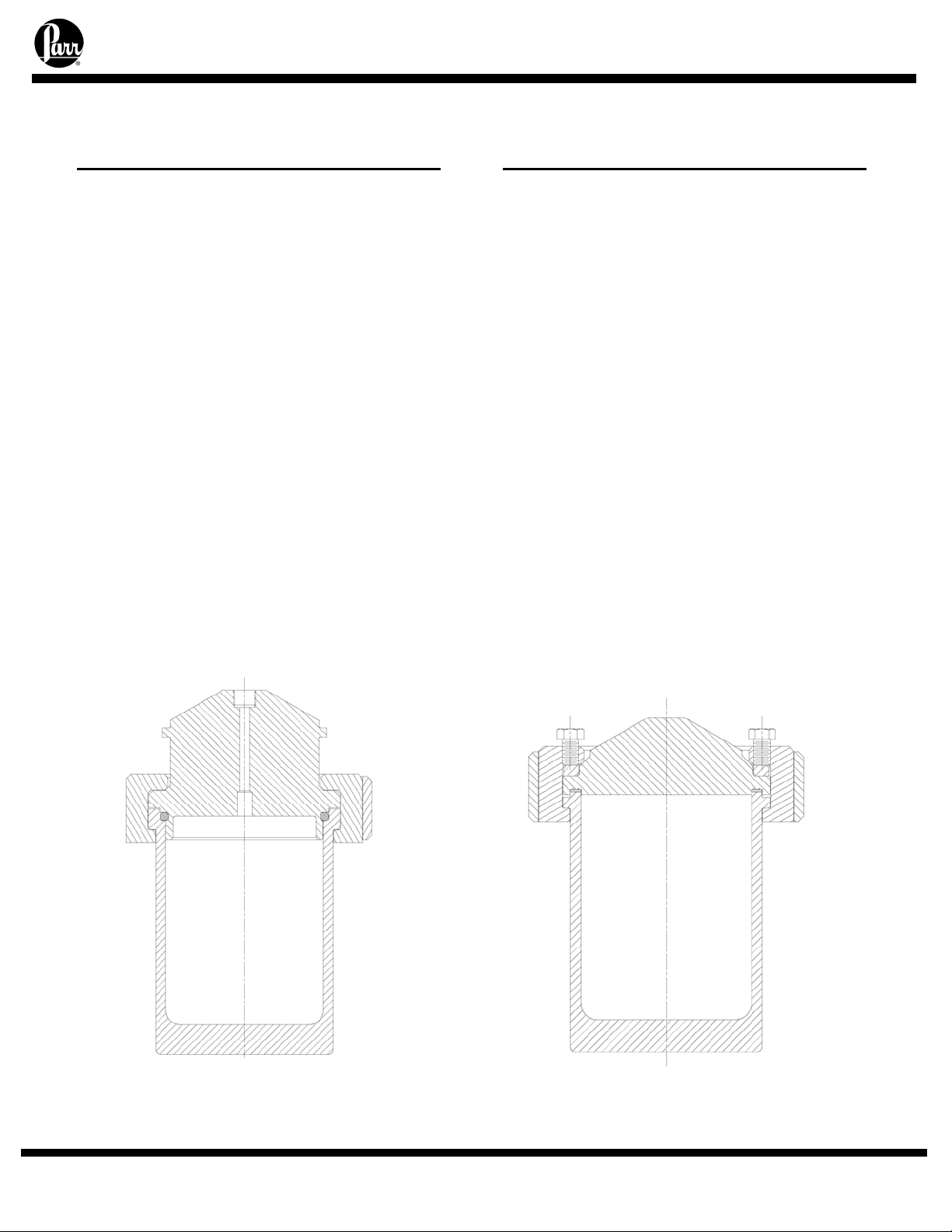
Fixed Head with O-ring
Flat PTFE Gasket or Self Sealing
O-ring Closure
The flat gasket is held in a recess in the
vessel head and a machine pilot on the
cylinder closes the recess to completely
contain the gasket. The split ring closure
used with this gasket has six cap screws
which must be tightened to develop the
loading on the gasket.
The self sealing design features an Oring retained in a groove on the vessel head.
This design is self sealing and the split ring
used with this sealing system does not
require nor have the cap screws used with
the flat gasket.
The flat PTFE gasket can be used to
operating temperatures as high as 350 C.
The maximum temperature of the vessels
equipped with O-ring seals depends upon
the material used for the O-ring. The most
common material is a fluoroelastomer (FKM)
which has a 225 C maximum operating
temperature limit.
Moveable Head with Flat Gasket
- 9 -
Page 10
Parr Instrument Company
IDENTIFY THE VALVES
Gas Release Valve
The gas release valve is mounted on an
extension in a 1/8” NPT port. This valve is
open to the gas head space of the cylinder.
This position also includes a 1/8” NPT
thread on the underside of the head which
may be used for a second dip tube or an
alternate accessory such as a catalyst
addition device.
Note: If a fitting is added to the
underside of the head in this location it will
be necessary to install an additional valve
on the gage adapter open to the gas space
of the vessel for pressure release.
Gas Inlet Valves
The gas inlet valve is easily identified
when the vessel is open by noting that it is
connected to a dip tube which extends to a
4520 Bench Top Reactors
point near the bottom of the cylinder. This is
an angle pattern valve with an attached
coupling which provides a socket for
attaching the A495HC gas hose furnished
with the reactor.
Liquid Sampling Valve
The liquid sampling valve is attached to
the same adapter as the gas inlet valve
combined with the dip tube. With this
arrangement, incoming gas is always
introduced below the surface of the liquid
and the operator is provided with a means
for clearing the dip tube to be sure that any
sample taken during a run will be
representative of the charge. This can be
done by opening the gas valve momentarily
to force any liquid in the tube back into the
reactor before withdrawing a sample from
the sampling valve.
- 10 -
Page 11

Parr Instrument Company
A
4520 Bench Top Reactors
Pressure Gage
Thermocouple
Gas Inlet Valve
Plug (extra port)
Gas Release Valve
Stirrer Shaft Assembly
djustable Impeller
Coupling for Gas Hose
Connection
Liquid Sampling Valve
Adapter Bushings
Thermowell
Dip Tube with Nut
Inlet Sampling Valve
Stirrer Support Bracket
Gas Release Valve
- 11 -
Page 12

Parr Instrument Company
4520 Bench Top Reactors
OTHER VESSEL HEAD FITTINGS
Safety Rupture Disc
There is a safety rupture disc attached to
the head which is intended to rupture and
release the pressure before it reaches a
dangerous level. A metal tag wired to the
safety head identifies the burst pressure at
room temperature for that particular disc. A
similar tag is furnished with each
replacement disc. This tag must remain with
the apparatus at all times so that both
present and future operators will be aware of
the disc rating. Users should read the
discussion of rupture discs given in the
Instruction Sheet No. 231M for a complete
description of the characteristics of rupture
discs and the precautions to be observed
when operating pressure equipment
protected by this type of safety device.
A typical pre-bulged disc can be used to
90% of the rating on the tag. For additional
protection, the user should install an
adequate and safe venting system for
removing any toxic, flammable or volatile
material which would be released if the
rupture disc should burst. A connector for
attaching 3/8” OD tubing to the discharge
port of the rupture disc is provided for this
purpose.
Type J Thermocouple
A Type J thermocouple with a 1/8” dia.
Stainless steel sheath is furnished with the
reactor. Insert this thermocouple into the
thermowell and connect it to the
thermocouple socket on the rear panel of
the temperature controller using the A470E2
extension wire furnished with the reactor.
Pressure Gage
The pressure gage furnished with this
reactor has a T316 Stainless Steel Bourdon
tube. Gages are furnished in a variety of
ranges to met individual needs. Typically,
the gage and the rupture disc are furnished
as matched ranges. For applications where
a gage is selected with a range under 1000
psi, a relief valve is added and set to protect
the gage. A 1000 psi rupture disc is
installed as the fail-safe vessel protection.
For highly corrosive applications where
the vapor phase might corrode the stainless
Bourdon tube, Parr offers isolator
assemblies in a variety of materials. These
isolators with their internal piston isolate the
vapors from the gage.
The gage adapter includes a ¼” NPT
side port with a plug installed. This position
may be used for a variety of fittings such as
a needle valve, pressure transducer or relief
valve.
Gage and Valve Adapters
The pressure gage and the combined
gas inlet and sampling valves are attached
to the head with an adapter which allows
these fittings to be drawn up tightly when
facing in any direction. To attach these
fittings to the head, screw the gage or valves
firmly into the adapter, then run the 209HC4
bushing onto the threaded stem as far as it
will go. Screw this assembly into the head
until the nose of the adapter is seated; then
back it off until the valve or gage is facing in
the desired direction. Now hold the fitting
firmly in place and close the joint by
tightening the 209HC4 bushing. This
connection can be made and broken
repeatedly without destroying the sealing
faces. A light coating of thread lubricant,
such as Parr No. 424HC2 High Temperature
Anti-Seize Lube, applied to the threads and
to the nose of the adapter will help to obtain
a tight joint.
Note: Do not use PTFE tape on the
straight thread connections of the coned
adapters and mating bushings. PTFE tape
should only be used on the (NPT) threads
such as the needle valves or gage
connection.
- 12 -
Page 13

Parr Instrument Company
4520 Bench Top Reactors
HOW TO USE THE VESSEL
PTFE Gasket or O-ring Seal
It is important to examine the main seal
of the head and cylinder before running any
experiments. Make certain that the gasket
or O-ring are in good condition. The seal
should not have any nicks or be hardened,
discolored or deformed. Examine the
mating surfaces of both the head and
cylinder to be sure they are clean and free
from burrs.
Fixed Head Vessel Installation
Lower the heater assembly and swing it to
the left for clearance while installing the
vessel assembly. Open the hinged retainer
bar and slide the square lip of the head into
the support plate. Close the hinged retainer
bar. Place the cylinder in the lift cup and
raise the cylinder up to the head. Place the
split rings around the head and cylinder and
close the split ring latches. Follow the bolt
tightening procedure below.
Moveable Head Vessel Installation
Lower the heater assembly and swing it
to the left for clearance while installing the
vessel assembly. With the vessel on the
countertop, mount the head on the cylinder.
Place the split rings around the head and
cylinder. Raise the drop band around the
split ring. Tighten the drop band bolt finger
tight. Follow the bolt tightening procedure
below before installing the vessel assembly
into the support frame. The split ring closure
rests on the top of the support plate
Sealing Vessels with PTFE Gaskets
First, hand tighten the six bolts. Then
using the open-ended wrench supplied with
the system. Proceed in a criss-cross pattern
to tighten the bolts to 25 ft/lbs. This can be
achieved by applying a firm but hard pull to
each bolt. Allow the vessel to stand for
about five minutes after the initial tightening
procedure to allow for the flow of the PTFE
gasket under load, then retighten the bolts.
Sealing Vessels with O-ring Seals
Moveable head vessels with O-ring seals
include a split ring and a drop band. Place
the split rings around the head and cylinder.
Raise the drop band around the split ring
placing the band so that the bolt will tighten
into the dimple on the split ring. Tighten the
drop band bolt finger tight.
Fixed head vessels with O-ring seals
include a split ring with latches. Place the
split rings around the head and cylinder.
Close the latches.
Gas Inlet / Liquid Sampling Valves
These reactors include a double valve
assembly with a common dip tube. This
arrangement allows the introduction of gas
into the liquid level as well as the ability to
take samples while the vessel is under
pressure. The A146VB angle pattern valve
at the top is the gas inlet position. The
A122VB straight needle valve mounted on
the side of the 208HC10 adapter is the liquid
sampling valve.
Gas Connections
The A495HC pressure hose is made of
reinforced Nylon which can be used at
ambient temperature for all non-corrosive
gases at pressures up to 2500 psig. This
hose is furnished with a male “A” socket
connection which will attach to the 420HC
coupling installed on the gas inlet valve
above the internal dip tube. The other end
includes a ¼” NPT male bushing with a
alternate 1/8” NPT male thread underneath
for attachment to the gas tank valve.
To attach the hose, pull back the nut,
rotate the sleeve back as far as it will go
toward the nut, insert it into the coupling and
then tighten the compression nut firmly.
Note: This assembly acts like a pipe union,
allowing the hose to remain stationary while
the joint is tightened.
- 13 -
Page 14

Parr Instrument Company
HOW TO USE THE VESSEL
(
Continued)
For applications involving corrosive
gases the nylon hose should be replaced
with the A490HC hose which includes a
PTFE lining and a braided stainless steel
outer covering. The A506HC hose is
constructed of T316 stainless steel (or other
corrosion resistant materials) is also
available for severe conditions.
Pressurizing the Vessel
Check all of the needle valves before
introducing gas to the vessel. The A122VB
liquid sampling valve must be in the closed
position throughout the charging procedure.
The gas release valve should also be in the
closed position unless it is to be used to
purge the vessel or run in a continuous
mode of operation.
It is important to make certain that the
pressure in the gas tank is greater than the
pressure in the vessel. If the vessel
pressure is greater than the gas tank , liquid
will be forced out of the vessel and into the
gas supply when the inlet valve is open. If
there is any possibility that the gas tank
pressure might not be sufficient, install a one
way check valve in the gas line to prevent
any reverse flow. (Hoses with check valves
are available upon request) After the
desired pressure has been reached, close
the valves and disconnect the hose
assembly at the vessel side.
Do Not Overfill the Vessel
Monitor the pressure gage of the vessel
when admitting gas. Be aware of the
maximum pressure limits of the vessel and
allow for expansion as a result of the heating
process.
As a general rule, the liquid charge
should not exceed two-thirds of the capacity
of the cylinder. Too much liquid in the
vessel can lead to the development of
dangerous pressures if sufficient space is
not available for expansion when the
4520 Bench Top Reactors
material is heated. See the Safety
Instruction Manual No. 230M for additional
details and potential hazards.
Withdrawing Liquid Samples
Liquid samples may be withdrawn from
the sampling valve attached to the same
adapter as the gas inlet valve whenever the
vessel is pressurized. Always close the inlet
valve before withdrawing a liquid sample
and open the sampling valve cautiously
because liquid will be discharged with
considerable force. Be particularly careful if
the temperature of the sample is above its
boiling point at atmospheric pressure. If so,
it will “flash” and be lost as soon as it is
released from the vessel. This problem can
be avoided by connecting an optional 4351
Sample Collection Vessel to the sampling
valve to collect the liquid into an appropriate
receiver. The addition of a small amount of
gas can be used to clear the dip tube
between liquid samples so that the next
sample drawn through the tube will truly be
representative of the mixture.
Releasing Pressure
The gas release valve is used to reduce
the pressure in the vessel if the system is
accidentally overcharged when filling. It is
also used to release any excess pressure
during a run and to exhaust the vessel at the
end of a test.
If the discharge gases are flammable or
toxic, a line should be added to the valve to
discharge into an appropriate containment or
exhaust system.
- 14 -
Page 15

Parr Instrument Company
4520 Bench Top Reactors
HOW TO USE THE VESSEL
(
Continued)
To Open the Vessel at Completion
of a Test
Fixed Head Units: Lower the heater
and swing it out of the way. Raise the
cylinder support to the cylinder bottom.
Open the gas release valve to discharge any
internal pressure. The split ring closure may
now be removed by unscrewing the bolts or
opening the latches. The head with all of the
attached fittings may remain in the support
plate. The cylinder can be lowered away.
Care should be taken when removing the
cylinder so damage will not occur to the
internal fittings.
Moveable Head Units: Lower the
heater and swing it out of the way. Open the
gas release valve to discharge any internal
pressure. Remove the complete vessel
assembly from the support stand and place
it on a countertop. The split ring closure
may now be removed by unscrewing the
bolts or opening the latches. Care should be
taken when lifting the head from the cylinder
so damage will not occur to the internal
fittings.
Initial Operating Test
Read all operating instructions carefully
so as to be well acquainted with the correct
procedures for handling the vessel and for
operating the controller and other
accessories. An initial operating test should
be made, with only water, to check the
apparatus before starting the first
experimental runs. For this initial test, fill the
cylinder not more than half full of water and
run the temperature up to 150ºC while
checking the apparatus for leaks and
observing the performance of the
temperature controller.
Variable Speed Electric Motor
Reactors are normally equipped with a
DC variable speed motor supplied and
controlled through the Series 4848
Controller. Instructions for connecting and
operating these motors are included in the
controller instruction sheet No. 548M. This
motor is usually installed in a drive system
designed to produce stirring speeds from 0
to 600 rpm. Higher speeds (1000 or 1700
rpm) can be obtained by substituting larger
diameter motor drive pulleys.
- 15 -
Page 16

Parr Instrument Company
4520 Bench Top Reactors
ACCESSORIES
Internal Cooling Coils
Cooling coils may be installed in any of
these reactors. The heads of the one and
two liter vessels are drilled with 1/8” NPT
connections on the top and underside of the
head. These openings will have plugs
installed if a cooling coil was not required
when the system was furnished.
The standard cooling coil is a serpentine
configuration. These coils provide an
effective cooling area and may be used with
either a Pyrex or PTFE liner. An optional
spiral coil is available which offers a larger
surface area for cooling but it is more difficult
to clean. The spiral coil can not be used
with an internal liner and it may not
coordinate with other optional internal
fittings.
The A160HW3 solenoid valve package is
recommended for use with the internal
cooling coil. This package includes the
solenoid valve, a metering valve and the
parts required to automate and control the
cooling process. This assembly will connect
to the cold water line, the cooling coil and to
the temperature control. Cooling will then be
admitted to the coil whenever cooling is
called for by the temperature control. This
system is particularly advantageous when
holding fixed temperatures below 150 °C or
to control exothermic reactions.
Alternate plugs are available to close
these ports when the coil is removed.
The replacement of a cooling coil will
require new nuts and ferrules for installation.
Align the replacement coil with the internal
fittings before tightening the nuts. Once the
nuts are tightened it may be necessary to
manually squeeze or slightly adjust the
serpentine loops of the coil to position it
properly for clearance.
If an internal cooling coil is not required
these two ports may be used for alternate
fittings such as an additional valve with a
second dip tube.
Liners
Glass or PTFE liners can be furnished to
fit most Parr reactors. These liners slide into
the cylinder. Although they will not keep
corrosive vapors from reaching the surfaces
of the cylinder and head, they make it much
easier to add and remove liquid reactants,
and they give some protection to the cylinder
when working with corrosive solutions. It
must be noted, however, that adding a liner
will slow the heat transfer rate into the
vessel, and it may be necessary to adjust
the temperature control method to prevent
overheating.
Liner Part Numbers
Fits
ID
4” 1000 mL 398HC 398HCHA
4” 2000 mL 399HC 399HCHA
Cylinder
Size
Spare Parts Kit
Parr can furnish spare parts kits for these
reactors which will provide a reserve supply
of parts and tools sufficient to handle most
normal replacements and emergency repairs
during a year of heavy usage.
These kits contain replacement gaskets,
packing, O-rings, shafts, bearings, and
rupture discs. They can be ordered from
any Parr Dealer or direct from the Parr
Instrument Company. The order must
specify the reactor size and indicate type of
rupture disc, stirrer drive and whether it has
a flat-gasket or O-ring closure. Always
provide the reactor serial number (stamped
on head and cylinder) to assure receipt of
proper replacement parts.
Glass
Liner
PTFE
Liner
- 16 -
Page 17

Parr Instrument Company
Air Motor
Variable speeds from 100 to 2000 rpm
can be obtained by replacing the standard
motor with an A1393HC air motor assembly.
This motor operates on compressed air
which must be supplied at 40 psig minimum
pressure with at least 10 CFM available at
that pressure. It is furnished with a speed
control valve and oiler, all assembled on a
mounting bracket.
To operate reactors equipped with an air
motor, mount the assembly firmly on the
stand and connect the air hose to a
compressed air line. For best torque and
speed control the piping to the motor should
be at least 1/4" IPS or larger. Fill the oiler
with SAE 10 oil and adjust the oiler to feed
one drop per minute into the air stream. For
long continuous runs at high speeds the
oiling rate should be increased to three
drops per minute.
Air Motor Option
4520 Bench Top Reactors
If the motor becomes sluggish, flush it
with a non-flammable solvent in a well
ventilated area. Disconnect the air line and
muffler and pour a small amount of solvent
into the inlet port. Rotate the shaft by hand
in both directions for a few minutes; then
connect the air line and run the motor until
there is no further trace of solvent in the
exhaust.
If the muffler felts are dirty, wash them in
solvent or replace them.
Re-lubricate the motor with a squirt of oil into
the chamber and reassemble.
If it becomes necessary to disassemble
the motor to replace the vanes, follow the
directions given in the instruction sheet
published by the Gast Manufacturing
Corporation, Benton Harbor, Michigan.
- 17 -
Page 18

Parr Instrument Company
EXPLOSION PROOF OPERATION
If the local safety code requires that
equipment installed in the user’s laboratory
must be explosion proof, there are four
possible ignition hazards to be considered:
1. The Motor
The standard adjustable speed motor
is not explosion proof, yet these motors
are not unduly hazardous if operated in a
well ventilated location where care is
taken to prevent the accumulation of
explosive gases or vapors. To eliminate
any possible spark hazard originating at
the motor, Parr can furnish an air motor
as described previously, or the reactor
can be equipped with a variable speed,
explosion proof motor that is approved
for use in Class 1, Groups C & D, and
Class 2, Groups E, F, & G atmospheres.
Explosion proof motors are furnished
with a temporary power cord and plug
which are not explosion proof. The user
should remove this temporary wiring and
replace it with an explosion proof switch
and wiring which will comply with the
local electrical code.
2. The Temperature Controller
The Series 4848 Temperature
Controllers furnished with these reactors
contain switches and other elements that
are not explosion proof. The minimal
spark hazard associated with these units
can be resolved by installing the
controller in a remote location outside of
the hazardous area or by enclosing it in
an approved explosion proof housing. If
enclosed within a positive pressure,
clean air housing, the discharge from the
housing must be directed into a safe
area. If requested, Parr will furnish the
long lead wires needed to mount the
controller in a remote location. If the
4520 Bench Top Reactors
controller is to be installed in an
explosion proof housing, the user must
provide the necessary housing and
installation.
3. The Heater
The elements in the heater could be
dangerous in an explosive atmosphere if
the surface temperature of the element
becomes high enough to ignite
flammable vapors. This hazard must be
evaluated for each individual installation
since major modifications are required if
the heater must be isolated from the
surrounding atmosphere. Users who
consider this a significant hazard are
urged to contact the Parr Instrument
Company for further discussion and
suggestions that might be helpful.
4. The Wiring
The wiring provided with the standard
reactor systems does not meet the
standards prescribed for explosion proof
operation. Optional, intrinsically safe
barriers are available.
- 18 -
Page 19

Parr Instrument Company
PERIODIC PRESSURE TESTS
Each cylinder used in a Parr stirred
reactor is tested under hydrostatic pressure
to 1.3 times its maximum rating before it is
released from the factory. Micrometer
caliper measurements are taken during this
test to check the deflection of the walls
under pressure. Excessive deflection or
failure of the metal to resume its original
dimensions after pressure is released
indicates that a cylinder is potentially unsafe
and it will be rejected. Similar tests should
be made at regular intervals during the life of
each cylinder, and particularly whenever the
user suspects that the equipment has been
over-stressed or damaged.
Some laboratories maintain hydraulic
test facilities and make it a rule that all
pressure vessels must be tested at regular
intervals. Records are kept of deflections at
specific test pressures so that any increase
in deflection becomes a warning that the
metal has lost strength. Any cylinder that
fails to return to its original dimensions after
application of the prescribed hydrostatic test
should be discarded as unsafe for further
use.
4520 Bench Top Reactors
Users who do not have pressure test
facilities can return any Parr pressure vessel
to the factory for hydrostatic testing and
overhaul. This should be done whenever
the metal shows excessive damage from
corrosion or whenever an over-pressure or
other unusual occurrence raises any safety
questions. To return a vessel for repair
contact Parr Instrument Company for a
return authorization number. Apparatus
returned for testing and overhaul should be
shipped prepaid to the Parr Instrument
Company, 211-53rd Street, Moline, Illinois
61265. An order or letter of instructions
should be mailed to the same address, as
no repair work will be started without specific
instructions and a Health & Safety
Assurance Certification form (F0042) signed
by a responsible user.
- 19 -
Page 20

Parr Instrument Company
GENERAL MAINTENANCE NOTES
1. Periodically inspect all electrical wiring
and pressure connections for excessive
corrosion. Suspect parts should be
replaced by components only supplied
by Parr Instrument Company.
2. Always use appropriate wrenches on all
fittings and valves. Never use pliers or
pipe wrenches.
3. Head and cylinder service fixtures are
available for convenience and protection
of components during maintenance of
your reactor.
4. To reinstall straight thread (NPS) fittings
to the head, screw the gage or valves
firmly into the adapter.
Run the bushing onto the threaded stem
as far as it will go. Screw this assembly
into the head until the nose of the
adapter is seated; then back it off until
the valve or gage is facing in the desired
direction (no more than one full turn).
Hold the fitting firmly in place and close
the joint by tightening the bushing. This
connection can be made and broken
repeatedly without destroying the sealing
surfaces. A light coating of thread
lubricant, such as Parr High Temperature
Anti-Seize Lubricant, applied to the
straight threads and to the nose of the
adapter will help to obtain a tight joint.
Note: PTFE tape should not be used on
this joint.
5. NPT (National Pipe Taper) threads
should not be disassembled any more
than necessary. It will become
increasingly difficult to maintain a tight
seal with these tapered threads if the
joint is made and broken repeatedly.
Grafoil tape or PTFE tape (if temp
allows) should be used on all NPT
threads.
6. Do not use oil or anti-seize lubricant on
threads or fittings if the vessel is to be
used with oxygen.
7. If your vessel is equipped with a loose
compression ring be sure that it is in place
on the head before attaching any head
4520 Bench Top Reactors
fittings. The compression ring cannot be
installed after fittings have been screwed
into the head.
8. Clean all threads and gas passages
thoroughly and remove all tape fragments
when overhauling a vessel. An ultrasonic
bath is excellent for cleaning metal parts,
but do not place a thermocouple probe,
pressure gage, face seals or ball bearings
in an ultrasonic bath. Periodic cleaning
may be performed on the exterior
surfaces of the reactor stand with a lightly
dampened cloth containing mild soap
solution. All power should be
disconnected when cleaning.
9. Routinely inspect cap screws on split ring
closure for lubrication and cleanliness.
These screws should not be allowed to
dry because the threads will seize.
Regularly apply Parr High Temperature
Anti-Seize Lubricant (Parr No. 424HC2)
before this happens.
10. To operate reactors equipped with an air
motor, connect air hose to a compressed
air line. For best torque and speed
control the piping to the motor should be
at least 3/8” IPS or larger. Fill the oiler
with SAE 10 oil and adjust the oiler feed
one drop per minute into the air stream.
For long continuous runs at high speeds,
the oiling rate should be increased to
three drops per minute. If the motor
becomes sluggish, flush it with a nonflammable solvent in a well ventilated
area.
Disconnect the air line and muffler and
pour a small amount of solvent into the
inlet port. Rotate the shaft by hand in
both directions for a few minutes; then
connect the air line and run the motor until
there is not further trace of solvent in the
exhaust. If the muffler is dirty, replace it.
Relubricate the motor with a squirt of oil
into the chamber and reassemble.
11. If servicing assistance is needed, contact
Parr Instrument Company directly at the
address shown on the back of these
instructions.
- 20 -
Page 21

Parr Instrument Company
4520 Bench Top Reactors
PARTS LISTS
Reaction Vessel Parts List
Consult the itemized list for your reactor
provided along with this manual. For purpose of
reactor identification, the following
abbreviation/codes are used:
FH RV FG -
Fixed Head
Removable Head
Flat Gasket
LD HD OS -
Part No. Description Code
Cylinders
236HC10 Cylinder, 1000 mL FG
236HC20 Cylinder, 2000 mL FG
2742HC10 Cylinder, 1000 mL OS
2742HC20 Cylinder, 2000 mL OS
HEADS
1370HC20 Head RVFG(LD)
2252HC20 Head FHFG(LD)
2740HC20 Head RVOS(LD)
2750HC20 Head FHOS(LD)
2259HC20 Head FHFG(HD)
2758HC20 Head FHOS(HD)
755HC50 Head RVFG(HD)
INTERNAL FITTINGS
THERMOWELL
265HC7 Thermowell 1000ml FH
265HC12 Thermowell 2000ml FH
STIRRER SUPPORT BRACKET
A380HC Stirring Bracket Assembly FG
A1404HC Stirrer Bracket Assembly OS
380HCF Cap screw for A380HC/ A1404HC bracket
299HC Bushing PTFE for A380HC/ A1404HC bracket
299HCKF Bushing, graphite for A380HC/ A1404HC bracket
DIP TUBE
257HC26 Dip Tube with nut, 1000 mL
257HC27 Dip Tube with nut, 2000 mL
Light Duty
Heavy Duty
O-ring Seal
For parts made from alternate materials use
the codes shown below as a suffix to the
standard part number.
CM CT CG CXA
CXB
Part No. Description Code
SHAFTS
352HC6 Stub shaft, A1120HC6, 2.56” RV(LD)
352HC9 Stub shaft, A1120HC6 , 3.98” FH(LD)
1025HC39 Stub shaft, A1180HC4, 5.76” FH(HD)
1025HC14 Stub shaft, A1180HC4, 4.12” RV(HD)
A449HC Shaft assembly with coupling,
A449HC2 Shaft assembly with coupling,
A1030HC Shaft assembly with coupling,
A1030HC2 Shaft assembly with coupling,
378HC Coupling, stirring shaft (LD)
379HC Pin, shaft, coupling (LD)
1028HC Coupling, stirrer shaft (HD)
1029HC Pin, shaft, coupling (HD)
447HC Shaft bushing, PTFE (LD)
1027HC Shaft, bushing, PTFE (HD)
448HC Shaft with 447HC bushing, 1000
448HC2 Shaft with 447HC bushing, 2000
1025HC Shaft with 1027HC bushing, 1000
1025HC2 Shaft with 1027HC bushing, 2000
A358HC2 Impeller with set screws, 2.28” dia
A358HC5 Impeller with set screws, 2” dia
358HC2F Set screws for impeller
GASKETS & SEALS
48HC Gasket, silver; thermowell and LD drive
48HCFG Gasket, gold plated; thermowell and LD drive
315HC2 Head Gasket, PTFE FG
2741HCJV O-ring FKM OS
2741HCJK O-ring FFKM OS
Alloy 400
Alloy 600
Alloy B-2
Zirconium G702
Zirconium G705
1000 mL
2000 mL
1000 mL
2000 mL
mL
mL
mL
mL
CC -
CAD CAA CH -
Alloy 20Cb3
Titanium G2
Titanium G4
Alloy C-276
(LD)
(LD)
(HD)
(HD)
(LD)
(LD)
(HD)
(HD)
21
Page 22

Parr Instrument Company
Part No. Description Code
EXTERNAL FITTINGS
94CAAD Plug, 1/4" NPTM
A122VB Needle Valve, 1/8" NPTM (Gas Sample)
A146VB Needle Valve, angled 1/8" NPTM (Gas
Release/Inlet)
208HC10 Valve adapter, two 1/8" NPTF
208HC15 Gage adapter, angled, two 1/4" NPTF
234HC Compression Ring
209HC4 Bushing
260HC2 Valve extension, 1/8" NPT (Gas Release)
288VBAD Male Connector, 3/8 T-1/4" NPTM
396HC3 Stirrer Plug (LD)
35HC Compression Nut, for plug (LD)
420HC Adapter, 1/8" NPTF to A socket (Gas Inlet)
A472E2 Thermocouple, 1000 mL
A472E6 Thermocouple, 2000 mL
A888HC2 Safety Rupture Disc assembly without disc
(see 231M)
A2685HC Cooling Sleeve assembly (LD)
A740HC Cooling Sleeve assembly (HD)
A1120HC6 Magnetic Drive assembly (LD)
A1180HC4 Magnetic Drive assembly (HD)
663HC Olive, drive seal (HD)
664HC Nut, Gland, drive seal (HD)
4520 Bench Top Reactors
Part No. Description Code
SPLIT RINGS AND ACCESSORIES
A232HC Split ring pair with cap screws RVFG
A2255HC3 Split ring pair with cap screws,
latches
232HCFDE Cap screw, for A232HC and A2255HC3
2245HC Split ring, pair RVOS
A2243HC Split ring, pair, with latches FHOS
A233HC Drop band with screw RV
GAGES
56HCPC Pressure gage, 4-1/2", 0-600 psi
56HCPD Pressure gage, 4-1/2", 0-1000 psi
56HCPF Pressure gage, 4-1/2", 0-2000 psi
FHFG
- 22 -
Page 23

Parr Instrument Company
Removable Head Style Parts Lists
4520 Bench Top Reactors
Front View
Removable Head Flat Gasket
- 23 -
Page 24

Parr Instrument Company
4520 Bench Top Reactors
Removable Head Flat Gasket
- 24 -
Page 25

Parr Instrument Company
Fixed Head Style Parts Lists
4520 Bench Top Reactors
Front View
Fixed Head Flat Gasket
Light Duty Footless Mag Drive
- 25 -
Page 26

Parr Instrument Company
4520 Bench Top Reactors
Back View
Fixed Head Flat Gasket
- 26 -
Page 27

Parr Instrument Company
4520 Bench Top Reactors
Fixed Head Flat Gasket
- 27 -
Page 28

Parr Instrument Company
Overarm Parts List
Part No. Description Code
MOTOR
1355EES Motor VS/PM130VDC 1/8 HP LD
A1554EES Motor VS/PM 130VDC 1/8 HP
with EMC filter
A1393HC Air Motor LD
A388E6 Air Motor HD
A388EES Motor 1/4 HP VS 90 VDC HD
A388E2ES Motor 1/2 HP VS 90VDC HD
A388EEQ Motor 1/4 HP EXP VS 90 VDC HD
A388E2ET Motor 1/2 HP VS 180 VDC HD
A388EER Motor 1/4 HP EXP VS 180 VDC HD
A388EET Motor 1/4 HP VS 180 VDC HD
DRIVEN PULLEY ASSEMBLY
A2179HC Driven Pulle y Assembl y LD
839HC Ball Bearing LD
841HC Snap R ing, External .693" LD
842HC Snap Ring, 1.804" LD
858HC2 Pulley, Driven LD
862HC Support Hub LD
299HC2 Bushing, PTFE LD
A2519HC Driven Pulle y Assembl y HD
706HC2 Pulley, Driven HD
725HC Support Hub HD
730HC Ball Bearing HD
731HC Snap R ing Internal 2" HD
732HC Snap Ring External 1" HD
2429HC Bushing PTFE HD
UPPER DRIVE SHAFTS
A2562HC Upper Drive Shaft , A1120HC LD
A2562HC2 Upper Drive Shaft, A2140HC LD
A2564HC Upper Drive Shaft, A1120HC6,
¼ hp motor
A2564HC2 Upper Drive Shaft , 1/4 -1/2 hp,
A1180HC
LD
LD
HD
4520 Bench Top Reactors
Part No. Description Code
SHAFT COUPLINGS
2075HC Shaft Coupling .38, Universal (LD)
2352HC Shaft Coupling .50, Universal (HD)
RELEASE KNOBS
845HC2 Release Knob, .38 Shaft LD
726HC Rele ase Knob, .50 Shaft HD
DRIVE PULLEYS (MOTOR)
857HC Pulley 600 RPM LD
857HC3 Pulley 800 RPM LD
857HC4 Pulley 1000 RPM LD
857HC5 Pulley 1700 RPM LD
695HC5 Pulley 800 RPM .62 HD
695HC3 Pulley 1000 RPM .62 HD
695HC2 Pulley 1700 RPM .62 HD
PULLEY BELT COMBINATIONS (LD DRIVE)
LD Pulley Belt
857HC 847HC9
857HC3 847HC9
857HC4 847HC9
857HC5 847HC10
PULLEY BELT COMBINATIONS (HD DRIVE)
HD Pulley Belt
695HC5 728HC5
695HC3 728HC5
695HC2 728HC6
OPTIONAL TACH PARTS
1564HC Optical Wheel
A1001E Tach Sensor Assembly (9.0"L)
A1001E2 Tach Sensor Assembly (5.5"L)
- 28 -
Page 29

Parr Instrument Company
Overarm Assembly
4520 Bench Top Reactors
- 29 -
Page 30

Parr Instrument Company
4520 Bench Top Reactors
Cooling Coil Parts List
Part No. Description
2998HC10 Cooling Coil, Serpentine 1L
2998HC20 Cooling Coil, Serpentine 2L
A92HWAD Male Connector, T316SS*
217VBAD Nut for tube 1/4", T316SS*
218VBAD Ferrule for tube 1/4", T316SS*
885HC2 Plug, 1/4" T Cap & Nut
* Used in both top and bottom on the head. Change to
appropriate material suffix for special alloy vessels for
internal connection.
- 30 -
Page 31

Parr Instrument Company
4520 Bench Top Reactors
Vessel Heaters Parts List
Part No. Description
FOR FIXED HEAD VESSELS
A2256HC10EB Heater Assembly 1000W 115V 1L
A2256HC10EE Heater Assembly 1000W 230V 1L
A2256HC12EB Heater Assembly 1000W 115V 1L w/
thermowell
Part No.
A2256HC12EE Heater Assembly 1000W 230V 1L w/
A2256HC20EB Heater Assembly 1500W 115V 2L
A2256HC20EE Heater Assembly 1500W 230V 2L
A2256HC22EB Heater Assembly 1500W 115V 2L w/
A2256HC22EE Heater Assembly 1500W 230V 1L w/
Description
thermowell
thermowell
thermowell
Benchtop Stand Arrangement
- 31 -
Page 32

Revision 02/08/13
 Loading...