

Page 1
Operating Instruction Manual 451M
1564
Water Recirculation System
Page 2

Page 3
1564 Water Recirculation System Operating Instruction Manual
Operating Instructions
For the 1564 Water Recirculation System
Purpose
The 1564 Water Recirculation System provides a convenient means to operate a Parr
6300 Calorimeter when a constant supply of good quality tap water is not available.
This unit works in conjunction with a water cooler such as the Parr 1552 to provide a
“closed loop” and therefore a well-controlled, enclosed system.
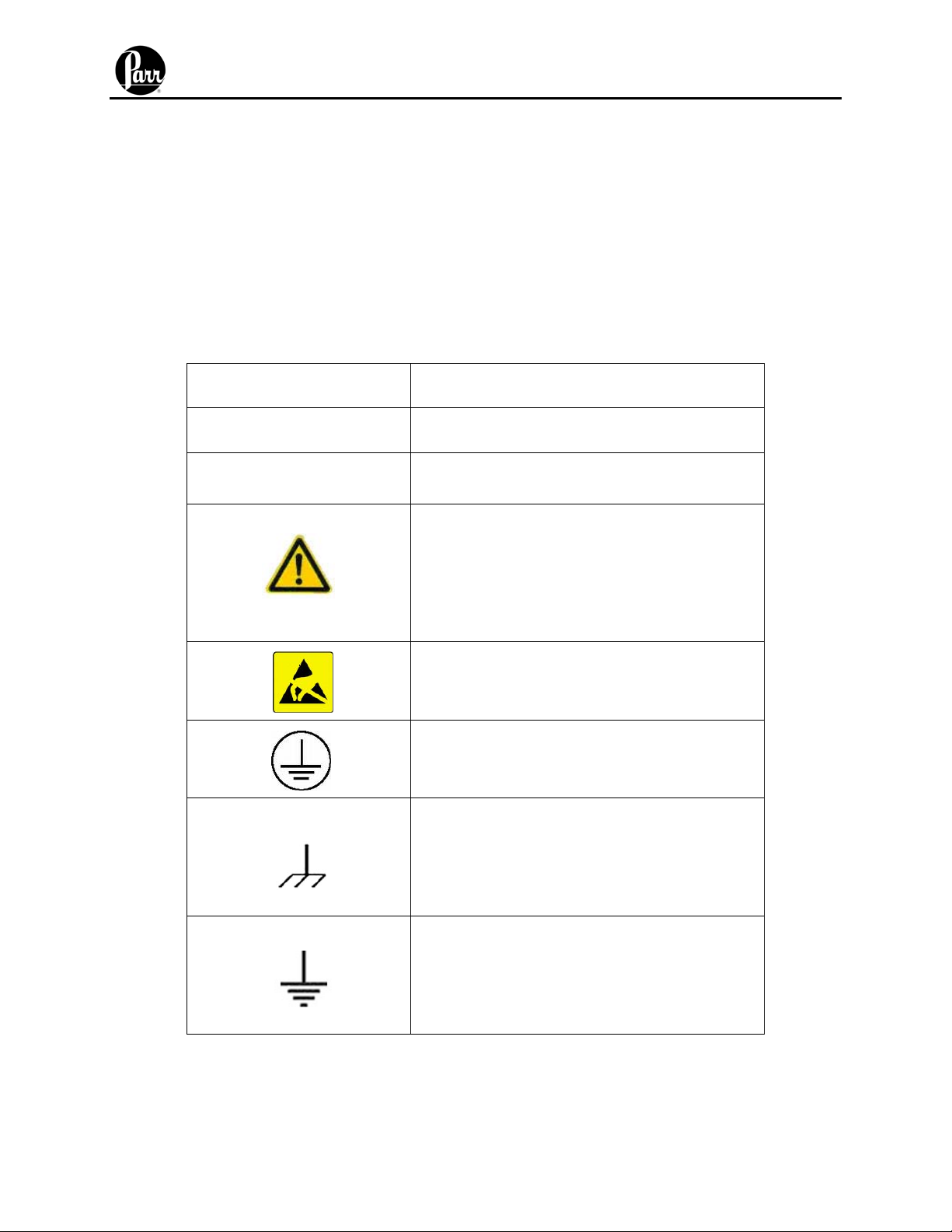
Explanation of Symbols
I
O
~
On position
Off position
Alternating Current (AC)
This CAUTION symbol may be present on
the Product Instrumentation and literature. If
present on the product, the user must
consult the appropriate part of the
accompanying product literature for more
information.
ATTENTION, Electrostatic Discharge (ESD)
hazards. Observe precautions for handling
electrostatic sensitive devices.
Protective Earth (PE) terminal. Provided
for connection of the protective earth (green
or green/yellow) supply system conductor.
Chassis Ground. Identifies a connection to
the chassis or frame of the equipment shall
be bonded to Protective Earth at the source
of supply in accordance with national and
local electrical code requirements.
Earth Ground. Functional earth connection.
NOTE: This connection shall be bonded to
Protective earth at the source of supply in
accordance with national and local electrical
code requirements.
- 2 -
Page 4

1564 Water Recirculation System Operating Instruction Manual
Safety Information
To avoid electrical shock, always:
1. Use a properly grounded electrical outlet of correct voltage and current handling
capability.
2. Ensure that the equipment is connected to electrical service according to local
national electrical codes. Failure to properly connect may create a fire or shock
hazard.
3. For continued protection against possible hazard, replace fuses with same type
and rating of fuse.
4. Disconnect from the power supply before maintenance or servicing.
To avoid personal injury:
1. Do not use in the presence of flammable or combustible materials; fire or
explosion may result. This device contains components which may ignite such
material.
2. Refer servicing to qualified personnel.
Intended Usage
If the instrument is used in a manner not specified by Parr Instrument Company, the
protection provided by the equipment may be impaired.
General Specifications
Electrical Ratings
115VAC, 2.0 Amps. 50/60 Hz
230VAC, 2.0 Amps, 50/60 Hz
Before connecting the water recirculation system to an electrical outlet, the user must
be certain that the electrical outlet has an earth ground connection and that the line,
load and other characteristics of the installation do not exceed the following limits:
Voltage: Fluctuations in the line voltage should not exceed 10% of the rated nominal
voltage shown on the data plate.
Frequency: Water recirculation systems can be operated from either a 50 or 60 Hertz
power supply without affecting their operation or calibration.
Current: The total current drawn should not exceed the rating shown on the data plate
on the water recirculation system by more than 10 percent.
Environmental Conditions
Operating: 15ºC to 30ºC; maximum relative humidity of 80% non-condensing.
Installation Category II (overvoltage) in accordance with IEC 664.
Pollution degree 2 in accordance with IEC 664.
Altitude Limit: 2,000 meters.
Storage: -25ºC and 65ºC; 10% to 85% relative humidity.
- 3 -
Page 5

1564 Water Recirculation System Operating Instruction Manual
Description
The system consists of a 1.5 gallon reservoir to receive the overflow from the 6300
Calorimeter, a recirculation pump, and a power supply. As the calorimeter flushes and
cools the bomb, the overflow water drains freely into the reservoir. The recirculation
pump then pumps water back to the calorimeter on demand.
Required Accessories and Utilities
A separate water cooler must be used with the 1564 system to remove the heat
introduced by each calorimeter test. A Parr 1552 Water Cooler is recommended for this
purpose. The cooler must be placed between the 1564 system and the 6300
Calorimeter. The circulating pump in the 1564 system provides enough pressure for
both the cooler and the calorimeter.
Approximately 4 L of water with a total hardness of less than 85 ppm is required for
filling the tank of the system.
Installation
Install the 1564 system below and near the calorimeter so that the cooling and overflow
water can drain freely from the calorimeter. This instrument is to be used indoors and
requires 3 square feet of space below the calorimeter in a well-ventilated area with
convenient access to an electric outlet. The supply voltage must be within ± 10% of
marked nominal voltage on the instrument. The supply voltage receptacle must have an
earth ground connection.
The water cooler can be installed in any convenient location however care should be
taken that heat from the compressor not reach the calorimeter. Additionally, air must be
allowed to move freely from the cooling fan into the cooler.
Make the tubing connections as illustrated in Figure-1.
Note: It is critical to keep the tubing between the calorimeter and the water
system as short as possible and eliminate any uphill runs or kinks. This
will impede the free flow of water from the calorimeter.
Connect the A1336DD drain tube assembly from the 412VB union bulkhead, labeled
Drain, on the back panel of the calorimeter to the 271HWHJ hose barb on the top of the
1564 Water Recirculation System. The A1336DD drain tube assembly is supplied in the
A1267DD accessory and installation kit of the 6300.
Connect the supplied ¼” tubing from the female connector (P/N 526VBAD) labeled
“Water Outlet” on the back panel of the Water Recirculation System to the union elbow
(P/N 496VB) labeled “Water In” on the top of the water cooler.
Connect the supplied ¼” tubing from the union elbow (P/N 496VB) labeled “Water Out”
on the top of the water cooler to the female connector (P/N 477VB) labeled “Water” on
the back panel of the calorimeter.
- 4 -
Page 6

1564 Water Recirculation System Operating Instruction Manual
Provisions for Lifting and Carrying – Before moving the instrument, disconnect all
connections from the rear of the apparatus. Lift the instrument by grabbing
underneath each corner.
Operation
Using water with less than 85 ppm total hardness, fill the water tank (P/N A262HW) to
within 10 cm (4 inches) of the top. Take care not to fill the tank with water higher than
the tube that enters through the side of the tank. Approximately 4L (1 gal) will be
required.
Do not apply power to the cooler at this time.
Check the voltage requirements of the system by examining the data label found on the
back of the unit. Plug the power cord into a suitable electrical outlet. Turn on the water
recirculation system by flipping the switch to the “ON” position. This will start the pump
that delivers water through the cooler and on into the calorimeter. Monitor the amount
of water in the water tank. Add water as required to maintain the water level in the
reservoir. Check for water leaks in the external lines and fix as required.
Check the voltage requirements of the calorimeter by examining the data label found on
the back of the unit. Plug in the power cord to a suitable electric outlet. Turn on the
calorimeter by flipping the switch to the “ON” position. This will open a water solenoid
inside the calorimeter that allows the calorimeter jacket to begin filling.
Note: Do not turn on the calorimeter heater and pump until the calorimeter
jacket is full otherwise damage can occur to the unit.
This initial filling process can take upwards of fifteen minutes to complete. During this
time, the pump in the 1564 Water Handling System will cycle on and off as required in
order to maintain pressure in the water lines. As the calorimeter jacket is filled, continue
to add water as required in order to maintain the water level in the reservoir of the water
handling system.
Make sure that the voltage requirements of the water cooler correspond to the rating on
the data plate. After the calorimeter jacket is filled and the water level in the water tank
of the 1564 Water Handling System tank has reached equilibrium, apply power to the
water cooler. Activate the calorimeter heater and pump.
Note: Allow one-half hour for these units to reach their normal operating
temperature.
- 5 -
Page 7

1564 Water Recirculation System Operating Instruction Manual
Preventative Maintenance
The following preventative maintenance for the 1564 Water Handling System is
recommended:
Change the water in the tank monthly.
Change the in-line filter, 149C, every 3 months
Replace the
3
/8OD tubing, HX0038TB062, annually
Wipe exterior surfaces with lightly dampened cloth containing mild soap solution.
Add an anti-microbial solution, such as VWR Clear Bath Algicide (13272-031), per the
manufacturer’s instructions.
There are no user serviceable parts inside the product other than what is specifically
called out and discussed in this manual. Advanced troubleshooting instructions beyond
the scope of this manual can be obtained by calling Parr Instrument Company in order
to determine which part(s) may be replaced or serviced.
Fuses
Lines protective fuses rated: Fast-Act 15 Amp, 250VAC (Parr number 139E23)
The replacement of protective fuses for the 1564 Water Recirculation System should be
performed by qualified personnel.
- 6 -
Page 8

1564 Water Recirculation System Operating Instruction Manual
Parts List
Part No. Description
451M Operating Instructions for the 1564
Water Recirculation System
139E23 Fuse Fast/ Act 15 Amp 250V
149C In-line Filter
HX0038TB062 Tubing, Bev-A-Line, 3/8” OD
271HWHJ Hose Barb, Male 1/2M-Barb
526VBAD Female Connector,
496VB Elbow, Union
1
1
/4T X ½ NPTF
/4T Brass
A262HW Water Tank
A1418DD Cooling Pump Assembly
230HW Tube Elbow Union 3/8T-T stem
261HW Female Connector,
3
/8T-1/2NPTF
258HW End Cap, Water Tank
1795E Power Supply, 24V
WARNING: For continued protection against possible hazard,
replace fuses with same type and rating of fuse.
- 7 -
Page 9

1564 Water Recirculation System Operating Instruction Manual
Figure 1
- 8 -
Page 10

1564 Water Recirculation System Operating Instruction Manual
Figure 2
WARNING: For continued protection against possible hazard,
replace fuses with same type and rating of fuse.
- 9 -
Page 11

1564 Water Recirculation System Operating Instruction Manual
Figure 3
- 10 -
Page 12

Revision 04/11/08
PARR INSTRUMENT COMPANY
211 Fifty-Third Street
Moline, Illinois 61265 USA
309/762-7716 800/872-7720
Fax 309/762-9453
http://www.parrinst.com
• E-Mail: parr@parrinst.com
 Loading...