


 Loading...
Digital Disk Recorders
Operating Instructions
WJ-HD309A
Model Nos. WJ-HD316A
|
TIMER |
ALARM |
ERROR |
|
|
ALARM |
|
SUSPEND |
ALARM |
|
|
|
RESET |
OPERATE |
HDD 1 |
|
|
|
HDD 2 |
MONITOR1
MONITOR2
1
SHIFT 
 5
5
DISK SELECT 9
EL-ZOOM 13
2 6
COPY
10/0 14
3 |
4 |
|
SEQ |
||
OSD |
||
7 |
||
8 |
||
|
||
TEXT |
MARK |
|
11 |
||
12 |
||
|
||
15 |
LOGOUT |
|
16 |
||
|
|
STOP |
PLAY |
PAUSE |
|
|
|
|
||
|
|
|
|
|
PAN/ |
GOTO |
|
|
|
TILT |
|
|
|
|
|
LAST |
|
|
|
ZOOM/ |
|
PAN/TILT |
|
SEARCH |
A-B |
|
|
||
FOCUS |
SLOW |
|
|
|
|
REPEAT |
|
|
|
IRIS |
LISTED |
|
|
|
|
|
|
|
|
PRESET |
|
|
|
|
/AUTO |
|
|
|
|
|
|
BUSY |
|
|
 RECREC STOP
REV |
|
PULL |
|
FWD |
|
|
|
|
SETUP |
|
|
/ESC |
|
|
– |
|
|
|
+ |
|
SET |
|
|
|
Digital Disk |
|
|
Recorder |
|
|
WJ-HD |
316A |
Before attempting to connect or operate this product,
please read these instructions carefully and save this manual for future use.
ENGLISH VERSION
Caution:
Before attempting to connect or operate this product, please read the label on the top and bottom.
CAUTION
RISK OF ELECTRIC SHOCK
DO NOT OPEN
CAUTION: TO REDUCE THE RISK OF ELECTRIC SHOCK,
DO NOT REMOVE COVER (OR BACK).
NO USER-SERVICEABLE PARTS INSIDE.
REFER SERVICING TO QUALIFIED SERVICE PERSONNEL.
|
The lightning flash with arrowhead symbol, |
|
|
within an equilateral triangle, is intended to |
|
|
alert the user to the presence of uninsulated |
|
|
"dangerous voltage" within the product's |
|
|
enclosure that may be of sufficient magni- |
|
SA 1965 |
tude to constitute a risk of electric shock to |
|
persons. |
||
|
The exclamation point within an equilateral triangle is intended to alert the user to the presence of important operating and maintenance (servicing) instructions in the literature accompanying the appliance.
SA 1966
Power disconnection. Unit with or without ON-OFF switches have power supplied to the unit whenever the power cord is inserted into the power source; however, the unit is operational only when the ON-OFF switch is in the ON position. The power cord is the main power disconnect for all units.
For U.S.A
NOTE: This equipment has been tested and found to comply with the limits for a Class A digital device, pursuant to Part 15 of the FCC Rules. These limits are designed to provide reasonable protection against harmful interference when the equipment is operated in a commercial environment. This equipment generates, uses, and can radiate radio frequency energy and, if not installed and used in accordance with the instruction manual, may cause harmful interference to radio communications.
Operation of this equipment in a residential area is likely to cause harmful interference in which case the user will be required to correct the interference at his own expense.
FCC Caution: To assure continued compliance, (example - use only shielded interface cables when connecting to computer or peripheral devices). Any changes or modifications not expressly approved by the party responsible for compliance could void the user’s authority to operate this equipment.
The serial number of this product may be found on the top and bottom of the unit.
You should note the serial number of this unit in the space provided and retain this book as a permanent record of your purchase to aid identification in the event of theft.
Model No.
Serial No.
WARNING: To prevent fire or electric shock hazard, do not expose this appliance to rain or moisture. The apparatus shall not be exposed to dripping or splashing and that no objects filled with liquids, such as vases, shall be placed on the apparatus.
2

LIMITATION OF LIABILITY
THIS PUBLICATION IS PROVIDED "AS IS" WITHOUT WARRANTY OF ANY KIND, EITHER EXPRESS OR IMPLIED, INCLUDING BUT NOT LIMITED TO, THE IMPLIED WARRANTIES OF MERCHANTABILITY, FITNESS FOR ANY PARTICULAR PURPOSE, OR NON-INFRINGEMENT OF THE THIRD PARTY’S RIGHT.
THIS PUBLICATION COULD INCLUDE TECHNICAL INACCURACIES OR TYPOGRAPHICAL ERRORS. CHANGES ARE ADDED TO THE INFORMATION HEREIN, AT ANY TIME, FOR THE IMPROVEMENTS OF THIS PUBLICATION AND/OR THE CORRESPONDING PRODUCT (S).
DISCLAIMER OF WARRANTY
IN NO EVENT SHALL MATSUSHITA ELECTRIC INDUSTRIAL CO., LTD. BE LIABLE TO ANY PARTY OR ANY PERSON, EXCEPT FOR REPLACEMENT OR REASONABLE MAINTENANCE OF THE PRODUCT, FOR THE CASES, INCLUDING BUT NOT LIMITED TO BELOW:
(1)ANY DAMAGE AND LOSS, INCLUDING WITHOUT LIMITATION, DIRECT OR INDIRECT, SPECIAL, CONSEQUENTIAL OR EXEMPLARY, ARISING OUT OF OR RELATING TO THE PRODUCT;
(2)PERSONAL INJURY OR ANY DAMAGE CAUSED BY INAPPROPRIATE USE OR NEGLIGENT OPERATION OF THE USER;
(3)UNAUTHORIZED DISASSEMBLE, REPAIR OR MODIFICATION OF THE PRODUCT BY THE USER;
(4)ANY PROBLEM, CONSEQUENTIAL INCONVENIENCE, OR LOSS OR DAMAGE, ARISING OUT OF THE SYSTEM COMBINED BY THE DEVICES OF THIRD PARTY.
(5)ANY CLAIM OR ACTION FOR DAMAGES, BROUGHT BY ANY PERSON OR ORGANIZATION BEING A PHOTOGENIC SUBJECT, DUE TO VIOLATION OF PRIVACY WITH THE RESULT OF THAT SURVEILLANCE-CAMER- A’S PICTURE, INCLUDING SAVED DATA, FOR SOME REASON, BECOMES PUBLIC OR IS USED FOR THE PURPOSE OTHER THAN SURVEILLANCE
(6)ANY PROBLEM, CONSEQUENTIAL INCONVENIENCE, ANY LOSS OR DAMAGE, ARISING OUT OF THE IMPROPER DETECTION OR SLIP-UP IN DETECTION BY VMD (Video Motion Detector) FUNCTION OF THE PRODUCT.
3

IMPORTANT SAFETY INSTRUCTIONS
1)Read these instructions.
2)Keep these instructions.
3)Heed all warnings.
4)Follow all instructions.
5)Do not use this apparatus near water.
6)Clean only with dry cloth.
7)Do not block any ventilation openings. Install in accordance with the manufacturer's instructions.
8)Do not use near any heat sources such as radiators, heat registers, stoves, or other apparatus (including amplifiers) that produce heat.
9)Do not misuse the polarized or grounding-type plug. A polarized plug has two blades with one wider than the other. A grounding-type plug has two blades and a third grounding prong. The wide blade or the third prong are provided for your safety. If the provided plug does not fit into your outlet, consult an electrician for replacement of the obsolete outlet.
10)Protect the power cord from being stepped on or pinched particularly at plugs, convenient receptacles and the points where they exit from the apparatus.
11)Only use attachments/accessories specified by the manufacturer.
12)Use only with the cart, stand, tripod, bracket, or table specified by the manufacturer, or sold with the apparatus. When a cart is used, use caution when moving the cart/apparatus combination to avoid injury from tip-overs.
S3125A
13)Unplug this apparatus during lightning storms or when unused for long periods of time.
14)Refer all servicing to qualified service personnel. Servicing is required when the apparatus has been damaged in any way, such as when the power-supply cord or plug is damaged, liquid has been spilled or objects have fallen into the apparatus, the apparatus has been exposed to rain or moisture, does not operate normally, or has been dropped.
4

PRECAUTIONS
•Refer all work related to the installation of these products to qualified service personnel or system installers.
•Do not operate the appliances beyond their specified temperature, humidity, or power source ratings.
Use the appliance at temperatures within +5 °C - +45 °C (41 °F - 113 °F) and humidity below 85 %.
The input power source for this appliance is 120 V AC 60 Hz.
Performance and lifetime of hard disk drives are easily affected by heat (used at high temperature) characteristically. It is recommended to use this appliance at temperatures within +20 °C - +30 °C (68 °F - 86 °F).
•Handle the appliance with care.
Do not strike or shake, as this may damage the appliance.
•Do not strike or give a strong shock to the unit.
It may cause damage or allow water to enter the unit.
•Built-in backup battery
Before the first use, charge the built-in backup battery (lithium battery) by turning on the power for 48 hours or more.
If it is not charged enough, in a case where the power goes down, the internal clock may keep bad time or the operative condition may be different to that before the electric power failure.
The built-in battery life is approximately 5 years as an indication of replacement. (This is just an indication of replacement. We are not providing any guarantee of the built-in battery lifetime. Replacement cost of the built-in battery is not covered by the warranty even if it needs to be done within the warranty period.) Ask the shop where you purchased the unit when replacement of the battery is required.
•Cooling Fan
Turn the power off when cleaning the unit. Otherwise it may cause injuries.
Replacement costs of the cooling fan are not covered by the warranty even if it needs to be done within the warranty period. Consult your dealer for servicing.
•Cleaning
Turn the power off when cleaning the unit. Otherwise it may cause injuries.
Do not use strong or abrasive detergents when cleaning the appliance body.
Use a dry cloth to clean the appliance when it is dirty. When the dirt is hard to remove, use a mild detergent and wipe gently.
•Indication label
Refer to the indication labels placed on the top and bottom of the unit as to the indications of equipment classification and power source, etc.
•Built-in hard disk drives
Hard disk drives are vulnerable to vibration. Handle them with care.
It is possible to damage them if they are moved while their motors are still running. Do not move them just after turning their power on or off (for around 30 seconds).
When hard disk drive trouble occurs, replace it immediately. Consult your dealer for servicing.
When replacing the hard disk drives, take notice of the following.
Do not detach the hard disk drives or the cables connecting the unit and the front cover while the HDD1/HDD2 indicators are lit or for around 30 seconds after the indicators go off.
Protect the hard disk drives from static electricity. Do not stack them, or keep them upright.
Do not use an electric screwdriver to fix them. (Tightening torque: Approx. 0.49 N · m (5 kgf · cm)) Avoid rapid changes of the temperature/humidity to prevent condensation. (Acceptable change: within 15 °C/h (59 °F/h))
•Place the unit horizontally an a level surface. Do not place the unit in an upright position. When stacking multiple units, clear a space of more than 5 cm from both sides, the top, the bottom and the rear of the units.
•Avoid placing receptacles that contain liquids such as water near the unit.
If liquid spills onto the unit, it may cause fire or an electric shock.
•Do not expose the unit to water or moisture, or try to operate it in wet areas.
•Prevent condensation from forming on the surface of the hard disk.
If this happens, do not turn on the power of the recorder and leave the recorder for around 2 hours.
Wait until the dew evaporates in any of the following cases:
•The recorder is placed in an extremely humid place.
•The recorder is placed in a room where a heater has just been turned on.
•The recorder is moved from an air-conditioned room to a humid and high-temperature room.
•We recommend that you make a note of your settings and save them. This will help when you are required to change the system configuration, or when unexpected trouble or failure occurs.
•Distributing, copying, disassembling, reverse compiling, reverse engineering, and also exporting in violation of export laws of the software provided with this product, is expressly prohibited.
5

TRADEMARKS AND REGISTERED TRADEMARKS
•Adobe, Adobe logos, and Acrobat are registered trademarks of Adobe Systems Incorporated in the U.S. and/ or other countries.
•Microsoft, Windows and Windows XP are registered trademarks of Microsoft Corporation in the U.S. and/or other countries.
•Other names of companies and products contained in these operating instructions may be trademarks or registered trademarks of their respective owners.
ABOUT THESE OPERATING INSTRUCTIONS
There are 3 sets of operating instructions for the WJ- HD316A/WJ-HD309A as follows.
•Operating Instructions (book, these operating instructions)
•Network Operating Instructions (PDF)
•Network Setup Instructions (PDF)
These "Operating Instructions" contain descriptions of how to operate this unit with the buttons on the front panel. Refer to the "Network Operating Instructions" on the provided CD-ROM for descriptions of how to operate this unit from a PC.
Refer to the "Network Setup Instructions" on the provided CD-ROM for descriptions of how to perform the required settings and how to connect to other devices.
Adobe® Reader is required to read these operating instructions (PDF) on the provided CD-ROM. When the Adobe® Reader is not installed on the PC, download the latest Adobe® Reader from the Adobe web site and install it.
"WJ-HD300" or "HD300" shown in the illustrations used in these operating instructions indicate this unit or the WJHD300 series.
6

CONTENTS
LIMITATION OF LIABILITY .............................................. |
3 |
DISCLAIMER OF WARRANTY ................................... |
3 |
IMPORTANT SAFETY INSTRUCTIONS .......................... |
4 |
PRECAUTIONS ................................................................ |
5 |
TRADEMARKS AND REGISTERED TRADEMARKS ...... |
6 |
ABOUT THESE OPERATING INSTRUCTIONS .............. |
6 |
PREFACE ......................................................................... |
8 |
FEATURES ....................................................................... |
8 |
MAJOR OPERATING CONTROLS AND |
|
THEIR FUNCTIONS ......................................................... |
9 |
■ Front View ................................................................... |
9 |
■ Rear View ................................................................... |
11 |
■ On Monitor 1 (To display only live image) .................. |
12 |
■ On Monitor 2 (To display live or recorded images) ..... |
13 |
STARTUP ......................................................................... |
17 |
CLOCK ADJUSTMENT .................................................... |
18 |
SHUTDOWN ..................................................................... |
19 |
RECORDING (Manual Recording) ................................... |
20 |
RECORDING (Emergency Recording) ............................. |
21 |
PLAYBACK ....................................................................... |
22 |
PLAYBACK IMAGE ON A DESIGNATED DISK ............... |
25 |
PLAYBACK FROM A DESIGNATED TIME |
|
AND DATE ........................................................................ |
27 |
SEARCH AND PLAY ........................................................ |
28 |
■ Search for a Recording Event and Play it back |
|
(Recording Event Search) .......................................... |
28 |
■ Search for Copied Recorded Images and Play it back |
|
(Copy Data Search) .................................................... |
32 |
■ Search for a motion detected time and date from |
|
the recorded images and play it (VMD search) .......... |
36 |
■ Search for a marked point and play from that point |
|
(Marking search) ......................................................... |
41 |
MONITOR LIVE IMAGES ................................................. |
42 |
■ Displaying Live Images on a Single Screen ............... |
42 |
■ Displaying on a Multi-screen ....................................... |
43 |
■ Sequential Display ...................................................... |
44 |
CONTROL CAMERAS ..................................................... |
45 |
■ Panning/Tilting ............................................................ |
45 |
■ Zoom ........................................................................... |
45 |
■ Focus .......................................................................... |
45 |
■ Iris ............................................................................... |
46 |
■ Preset Action .............................................................. |
46 |
■ Auto Function (Auto Pan, etc) ..................................... |
48 |
ABOUT THE EVENT FUNCTION ..................................... |
49 |
■ Action at an event occurrence .................................... |
49 |
■ Cancel the Alarm Action ............................................. |
51 |
■ Suspend the Alarm Actions ........................................ |
51 |
COPYING (Duplicate) ....................................................... |
52 |
DELETE DATA ON THE DISK ......................................... |
54 |
■ Deletion of recorded images saved on the |
|
hard disk manually ...................................................... |
54 |
FORMAT (INITIALIZE) A DVD-RAM DISK ....................... |
56 |
DISPLAY/EDIT TEXT INFORMATION ............................. |
58 |
ERROR/WARNINGS ........................................................ |
60 |
OPERATION USING A PC ............................................... |
63 |
■ Features ...................................................................... |
63 |
■ System Requirements of a PC ................................... |
63 |
OPERATION OF THE UNIT IN THE CASCADE |
|
CONNECTION .................................................................. |
64 |
■ Operation using the buttons on the front panel ........... |
64 |
■ Setup .......................................................................... |
64 |
■ Operation using the system controllers ...................... |
65 |
MANAGEMENT OF USERS/HOSTS ............................... |
66 |
OPERATING THE UNIT FOR THE FIRST TIME ............. |
68 |
Preparation for maintenance (HDD replacement, |
|
installation, etc.) .............................................................. |
69 |
INSTALLATIONS .............................................................. |
71 |
Places to avoid ............................................................... |
71 |
Rack mounting ................................................................ |
71 |
CONNECTIONS ............................................................... |
72 |
■ Connections when the unit is used independently ...... |
73 |
■ Connections with an extension unit ............................ |
74 |
■ Connections with DVD-RAM, CD-R, and |
|
DVD-R drives .............................................................. |
75 |
■ Connections with the VCR .......................................... |
76 |
■ Connections with PS·Data systems ............................ |
77 |
■ Cascade connection of multiple units ......................... |
79 |
■ Connection with the RS485 camera ........................... |
83 |
■ Mode Switch ............................................................... |
85 |
■ RS485 Port ................................................................. |
85 |
■ How to Use the Terminals of the ALARM/ |
|
CONTROL Connector ................................................. |
86 |
■ How to Use the Terminals of the ALARM |
|
Connector ................................................................... |
90 |
■ How to Use the SERIAL Connector ............................ |
92 |
SETUP .............................................................................. |
93 |
■ About the SETUP MENU (Quick) ............................... |
93 |
■ Item list of the SETUP MENU (Quick) ........................ |
93 |
■ [Display] ...................................................................... |
94 |
■ [REC & Event] ............................................................. |
97 |
■ [Network] ................................................................... |
100 |
■ About the SETUP MENU (Advanced) ...................... |
101 |
■ Item list of the SETUP MENU ................................... |
101 |
■ Basic Operation with the SETUP MENU |
|
(Advanced) ............................................................... |
104 |
■ [System] Settings on System .................................... |
105 |
■ [Recording] ............................................................... |
111 |
■ [Event] Function for Events ........................................ |
114 |
■ [Schedule] Settings for the recording/ |
|
event action schedule ............................................... |
119 |
■ [Switcher] Settings for the switcher function ............. |
124 |
■ [Display] ..................................................................... |
127 |
■ [Comm] Settings for communication with other |
|
devices ...................................................................... |
130 |
■ [Maintenance] Functions for Maintaining .................. |
135 |
DISPLAY SETUP MENU OF CAMERA .......................... |
139 |
DISK MANAGEMENT ..................................................... |
140 |
■ Notes on the hard disk ............................................... |
140 |
■ How to replace the built-in hard disk .......................... |
140 |
■ About the HDD DISK MENU ...................................... |
143 |
■ Display of the HDD DISK MENU ............................... |
143 |
■ RAID 5 Function of the Extension Unit ...................... |
144 |
■ Formatting (Initialization) the Hard Disk ..................... |
145 |
■ Setting for Mirroring ................................................... |
149 |
SERIAL (RS232C) CONNECTOR COMMAND |
|
REFERENCE .................................................................. |
153 |
■ SERIAL (RS232C) Communication Protocol ............ |
153 |
■ Command Format ..................................................... |
153 |
FLOWCHART OF THE SETUP MENU ........................... |
163 |
PARAMETERS AND THE DEFAULT SETTINGS |
|
OF THE SETUP MENU .................................................. |
164 |
TROUBLESHOOTING .................................................... |
172 |
SPECIFICATION ............................................................ |
176 |
STANDARD ACCESSORIES ......................................... |
177 |
7

PREFACE
The Digital Disk Recorders WJ-HD316A/309A are designed for use within a surveillance system and are a combination of a hard disk recorder and a video multiplexer (16-input for the WJ-HD316A, 9-input for the WJ-HD309A).
The digital hard disk recorder is a recording device using a hard disk drive to record camera pictures instead of using videotapes so that pictures recorded by repeated overwriting will not experience deterioration of the recorded picture quality. Up to 16 cameras can be connected to the WJ-
HD316A directly (up to 9 cameras to the WJ-HD309A) and it is possible to record their camera pictures. It is also possible to display four or more camera pictures on a single monitor, to switch camera pictures, and to operate cameras using this unit.
FEATURES
Various Recording Functions
•Multi-Recording
It is possible to perform multiple recordings using a single digital disk recorder even if the operating environments are different, for example, recording pictures of cameras in different places at different times.
Remote Operation via Network
It is possible to operate this unit using a PC connected to a LAN (Local Area Network) or the Internet with the featured network function.
•Schedule recording
It is possible to perform recording automatically at a scheduled time on a designated day of the week. Schedules can be set on each camera.
•Emergency Recording
In the case of an emergency, emergency recordings will be given a higher priority than other recording modes by operating an external switch.
•External Timer Recording
It is possible to perform recording automatically using an external timer.
•Event Recording
At an event occurrence, such as when an alarm signal is supplied, the recording mode (quality and recording rate) can be changed to high quality to record pictures.
•Motion Detection Function (VMD)
It is possible to start recording automatically when motion is detected in a shooting area.
Frame Switcher Function
•It is possible to display pictures of four or more cameras on a single monitor (multi-screen) splitting the monitor screen into 4, 7, 9, 10, 13, or 16 sections using the WJ-HD316A, and into 4, 7, or 9 sections using the WJ-HD309A.
While monitoring a multi-screen, each camera picture will be displayed as a moving image.
Security Function and Reliability
•Authentication function (registration of ID and password) allows users access to a predetermined selection of the available functions. Up to 32 users can be registered.
•If alteration of a recorded image data is made for any reason, the alteration alert function will announce it.
•If a hard disk crashes, the backup function*1, the mirroring function*2 and the RAID 5 function*3 prevent any data loss.
*1: Only when the recommended DVD-RAM drive, DVD-R drive or CD-R drive is used
*2: The mirroring function does not work with an external hard disk drive such as an extension unit.
*3: To use the RAID 5 function, an optional extension unit is required.
Transmission with Coaxial Cable, PS·Data and RS485 Compatible
•It is possible to control a Panasonic combination camera such as the WV-CS850 using only a coaxial cable but not other devices. Using a coaxial cable also compensates for transmission loss.
•It is easy to establish the surveillance system by connecting a PS·Data compatible system controller and peripherals.
8

MAJOR OPERATING CONTROLS AND THEIR FUNCTIONS
■ Front View
t o |
!8!9@0 |
|
qweryui |
!0 !1!5!6!7 |
@6 |
|
|
|
MONITOR1 |
|
|
|
|
STOP |
PLAY PAUSE |
REC - REC STOP |
|
PULL |
|
|
|
TIMER |
MONITOR2 |
|
|
|
|
|
|
|
REV |
FWD |
|
|
|
1 |
2 |
3 |
4 |
|
|
|
|
|
|
|
|
|
|
|
PAN/ |
GOTO |
|
|
|
|
|
||||
|
ALARM |
ERROR |
|
|
|
|
|
|
|
|
|
||
|
SHIFT |
|
SEQ |
OSD |
TILT |
LAST |
|
SEARCH |
|
|
|
||
|
|
|
|
|
|
|
|||||||
|
|
|
|
|
|
PAN/TILT |
|
SETUP |
|
|
|||
|
|
|
5 |
6 |
7 |
8 |
|
|
|
|
|
||
[WJ-HD316A] |
ALARM |
|
ZOOM/ |
A-B |
SLOW |
|
/ESC |
+ |
|
||||
SUSPEND |
ALARM |
|
|
|
|
FOCUS |
REPEAT |
|
|
– |
|
||
|
RESET |
DISK SELECT |
COPY |
TEXT |
MARK |
|
|
|
|
|
|
|
|
|
|
9 |
10/0 |
11 |
12 |
IRIS |
LISTED |
|
|
|
|
|
|
|
|
|
|
|
|
|
|
||||||
|
OPERATE |
HDD 1 |
EL-ZOOM |
|
|
LOGOUT |
PRESET |
|
|
|
|
|
|
|
|
|
|
|
|
|
|
|
|
||||
|
|
HDD 2 |
13 |
14 |
15 |
16 |
/AUTO |
|
|
|
SET |
Digital Disk Recorder |
|
|
|
|
|
BUSY |
|
||||||||
|
|
|
|
|
|
|
|
|
|
|
|
|
|
|
|
|
|
|
|
|
|
|
|
|
|
WJ-HD |
A |
!2!3!4@1@2@3 @4@5
t o |
!8!9@0 |
|
qweryui !0 |
!1!5!6!7 |
@6 |
|
|
MONITOR1 |
|
|
|
STOP |
PLAY |
PAUSE |
REC - REC STOP |
|
PULL |
||
|
|
MONITOR2 |
|
|
|
|
|
|
|
REV |
FWD |
|
|
|
|
TIMER |
1 |
2 |
3 |
|
|
|
|
|
|
|
|
|
|
|
PAN/ |
GOTO |
|
|
|
|
|
|
|||
|
ALARM |
ERROR |
|
|
|
|
|
|
|
|
|
||
|
|
|
|
TILT |
LAST |
|
SEARCH |
|
|
|
|||
|
SHIFT |
SEQ |
TEXT |
OSD |
|
|
|
|
|||||
|
|
|
|
PAN/TILT |
|
|
SETUP |
|
|
||||
[WJ-HD309A] |
|
|
4 |
5 |
6 |
|
|
|
|
|
|
||
ALARM |
|
ZOOM/ |
A-B |
SLOW |
|
|
/ESC |
+ |
|
||||
SUSPEND |
ALARM |
|
|
|
FOCUS |
REPEAT |
|
|
|
– |
|
||
|
RESET |
DISK SELECT |
COPY |
MARK |
|
|
|
|
|
|
|
|
|
|
|
|
7 |
8 |
9 |
IRIS |
LISTED |
|
|
|
|
|
|
|
OPERATE |
HDD 1 |
EL-ZOOM |
|
|
PRESET |
|
|
|
|
|
|
|
|
|
|
|
|
|
|
|
|
|
|
|||
|
|
HDD 2 |
|
0 |
|
/AUTO |
|
|
|
|
SET |
Digital Disk Recorder |
|
|
|
|
|
|
|
BUSY |
|
|
|||||
|
|
|
|
|
|
|
|
|
|
|
|
|
|
|
|
|
|
|
|
|
|
|
|
|
|
WJ-HD |
A |
!2!3!4@1@2@3 @4@5
@7@8@9 |
|
S-VIDEO |
|
COPY 2 |
VIDEO |
|
OUT |
|
AUDIO |
|
OUT |
|
#0 |
@7@8@9 |
|
S-VIDEO |
|
COPY 2 |
VIDEO |
|
OUT |
|
AUDIO |
|
OUT |
|
#0 |
qOperate Indicator (OPERATE)
Lights up when the power is turned on.
wAlarm Suspension Indicator (ALARM SUSPEND)
Lights up when the alarm suspension mode is selected.
eAlarm Indicator (ALARM)
Blinks when an alarm occurs, and lights steadily when the activated alarm is reset automatically.
To turn this indicator off, press the ALARM RESET button.
rAlarm Reset Button (ALARM RESET)
Pressing this button cancels alarm activation, and returns the system to the condition before the alarm was activated.
tError indicator (ERROR)
Blinks orange when an error occurs that will not keep the unit from running.
Blinks red when an error occurs that may cause the system to go down.
Refer to page 60 for further information about error/ warnings.
yTimer Indicator (TIMER)
Lights up when the schedule recording is set, and blinks while the schedule recording is being performed.
uHDD Access Indicators (HDD1/HDD2)
Blinks when the HDD1 or the HDD2 is accessed respectively.
iMonitor Switch button (MONITOR1/MONITOR2)
Pressing this button switches the monitor. This button lights up when monitor 1 is selected, and goes off when monitor 2 or the VGA monitor is selected.
oShift Button (SHIFT)
Toggles the functions of the camera selection buttons.
!0Camera Selection Buttons ([1] - [10/0], [11] - [16] for the WJ-HD316A, [1] - [9], [0] for the WJ-HD309A)
Pressing a button displays live or playback images of the selected camera. The LED in the button indicates the status as follows.
Green: When a button is lit green, the currently displayed image on the monitor is live from the respective camera.
Orange: When a button is lit orange, the image from the respective camera is recorded.
Blue: When a button is lit blue, the currently displayed image on the monitor is live from the respective camera and is also recorded.
9

When the shift button is lit, these buttons work as the toggled function buttons.
(The buttons available as the toggled function buttons will light green when the shift button is lit.)
!1Pan, Tilt, Latest Recorded Image Playback Button
(PAN/TILT, GO TO LAST)
Pans/tilts the selected camera, or plays back the latest recorded image.
(Refer to pages 45 and 23 respectively.)
!2Zoom, Focus, A - B Repeat Button (ZOOM/FOCUS,
A-B REPEAT)
Zooms in/out, adjusts focus, or repeats playback of recorded images between two designated points. (Refer to pages 45 and 23 respectively.)
!3Iris, Listing Button (IRIS, LISTED)
Adjusts iris, or enables/disables the filtering playback. (Refer to pages 46 and 28 respectively.)
!4Preset, Auto Function Button (PRESET/AUTO)
Moves a camera to the preset position, or activates the auto function of the camera.
(Refer to pages 46 and 48 respectively.)
!5Stop Button (STOP)
Stops playback.
!6Play/Pause Button (PLAY/PAUSE)
Plays recorded images, or pauses playback.
!7Record Button (REC/REC STOP)
Starts recording. To stop recording, press this button down for 2 seconds or more.
!8Slow Button (PAN/TILT, SLOW)
Pans/tilts the selected camera slowly.
!9Search Button (SEARCH)
Displays the search menu.
@0Setup, Escape Button (SETUP/ESC)
Displays the setup menu, or turns back to the previous page of the setup menu, etc.
@1Busy Indicator (BUSY)
Lights when the selected camera was not available to operate because another user is operating it using a controller or a PC via a network. In this case, wait until this indicator goes off.
@2Arrow Buttons (CDAB)
Adjusts zooming/focus, or moves the cursor on the setup menus and the search menu.
@3Set Button (SET)
Works differently depending on the situations listed below:
•Plays recorded images at the current playback speed when this button is pressed during fast playback.
•Registers preset positions of cameras.
•Activates the auto focus function.
•Resets the set iris.
•Sets the alarm suspension mode on/off.
•Determines the setting of parameters on the setup menus.
@4Jog Dial
Works differently depending on the situations as follows:
•Plays recorded images frame by frame when this dial is rotated during pausing playback.
•Skips playback time when this dial is rotated during playback at normal speed.
•Moves the cursor on the search menu or the thumbnail menu.
•Selects a parameter setting or a character on the setup menus.
@5Shuttle Ring
Works differently depending on the situations as follows:
•Plays fast when this ring is rotated during playback at normal speed.
•Turns the search menu pages or the thumbnail menu pages.
@6Connectors Cover
@7Copy Port (COPY2)
Connect a recommended external recording device to this port.
@8S-Video Output Connector (S-VIDEO)
Connect the S-video input connector of a VCR with this connector. The same video signal supplied to the MONITOR OUT2 connector on the rear panel will be supplied to this connector.
@9Video Output Connector (VIDEO OUT)
Connect the video input connector of a VCR with this connector. The same video signal supplied to the MONITOR OUT2 connector on the rear panel will be supplied to this connector.
#0Audio Output Connector (AUDIO OUT)
This connector, for an RCA standard jack, supplies an unbalanced –10 dBV, 600 Ω line output audio signal to an external device.
Recorded audio will be supplied from this connector during playback.
The same audio signal supplied to the AUDIO OUT connector on the rear panel will be supplied to this connector.
10
■ Rear View
[WJ-HD316A]
[WJ-HD309A]
|
|
|
|
|
|
|
|
o !0!1!3 !5 |
!8 |
|||||||
q w |
|
t y ui |
|
|
|
|
e !2!4!6 |
!7 |
||||||||
3 |
1 |
|
|
1 |
|
|
|
|
|
|
1 |
|
8 |
|
|
SIGNAL GND |
|
|
|
|
|
|
|
|
|
|
|
MODE |
|
|
|
||
|
|
|
|
|
|
SERIAL |
|
ALARM |
|
|
|
|
|
COPY 1 |
|
|
|
|
|
|
|
|
|
|
|
|
2 1 |
|
|
|
|
||
|
|
|
CASCADE |
|
|
|
|
|
|
|
|
|
|
|
|
|
4 |
2 |
|
OUT |
2 |
|
|
|
|
|
|
|
|
|
|
|
POWER |
AUDIO IN AUDIO OUT |
|
|
|
|
|
|
|
|
|
|
|
|
|
|
||
|
MONITOR OUT CASCADE IN MONITOR (VGA) |
|
ALARM/CONTROL |
|
|
DATA |
RS485(CAMERA) |
|
10/100BASE-T |
EXT STORAGE |
|
|||||
|
|
|
|
|
|
|
|
|||||||||
16 |
15 |
14 |
13 |
12 |
11 |
10 |
9 |
8 |
7 |
6 |
5 |
4 |
3 |
2 |
1 |
|
IN
AC IN
OUT |
|
|
|
|
|
|
|
|
|
|
|
|
|
|
|
|
|
16 |
|
15 |
14 |
13 |
12 |
11 |
10 |
9 |
8 |
7 |
6 |
5 |
4 |
3 |
2 |
1 |
|
|
|
|
|
|
|
|
|
VIDEO |
|
|
|
|
|
|
|
|
|
|
|
|
|
|
|
|
|
r |
|
|
|
|
|
@0 |
!9 |
||
|
|
|
|
|
|
|
|
|
o !0!1!3 !5 |
!8 |
|||||||
q w |
|
ty ui |
|
|
|
e !2!4!6 |
!7 |
||||||||||
3 |
1 |
|
|
|
1 |
|
|
|
|
|
|
1 |
|
8 |
|
|
SIGNAL GND |
|
|
|
|
|
|
|
|
|
|
|
|
MODE |
|
|
|
||
|
|
|
|
|
|
|
SERIAL |
|
ALARM |
|
|
|
|
|
COPY 1 |
|
|
|
|
|
|
|
|
|
|
|
|
|
2 1 |
|
|
|
|
||
|
|
|
|
CASCADE |
|
|
|
|
|
|
|
|
|
|
|
|
|
4 |
2 |
|
|
OUT |
2 |
|
|
|
|
|
|
|
|
|
|
|
POWER |
AUDIO IN |
AUDIO OUT |
|
|
|
|
|
|
|
|
|
|
|
|
|
|
||
|
MONITOR OUT CASCADE IN MONITOR (VGA) |
|
ALARM/CONTROL |
|
|
DATA |
RS485(CAMERA) |
|
10/100BASE-T |
EXT STORAGE |
|
||||||
|
|
|
|
|
|
|
|
|
|||||||||
|
|
|
|
|
|
|
IN |
9 |
8 |
7 |
6 |
5 |
4 |
3 |
2 |
1 |
|
|
|
|
|
|
|
|
|
|
|
|
|
|
|
|
|
|
|
|
|
|
|
|
|
|
|
|
|
|
|
|
|
|
|
|
AC IN |
|
|
|
|
|
|
|
OUT |
|
|
|
|
|
|
|
|
|
|
|
|
|
|
|
P S · D a t a |
|
9 |
8 |
7 |
6 |
5 |
4 |
3 |
2 |
1 |
|
|
|
|
|
|
|
|
|
|
|
|
VIDEO |
|
|
|
|
|
||
|
|
|
|
|
|
|
|
|
|
|
|
|
|
|
|
||
|
|
|
|
|
|
|
|
|
|
|
|
r |
|
|
@0 |
!9 |
|
qAudio Input Connectors (AUDIO IN 1 - 4)
These connectors, for RCA pin jacks, accept an unbalanced –10 dBV, 10 kΩ line input audio signal supplied
from an external device such as a microphone amplifier.
wAudio Output Connector (AUDIO OUT)
This connector, for an RCA standard jack, supplies an unbalanced –10 dBV, 600 Ω line output audio signal to
an external device.
Recorded audio will be supplied from this connector during playback.
eVideo Input Connectors (CAMERA IN 1 - 16 for the WJ-HD316A/CAMERA IN 1 - 9 for the WJ-HD309A)
Connect system cameras or combination cameras to these BNC connectors. Refer to page 72 for the impor-
tant notice about the BNC cables to be used.
A 75 Ω termination is made unless the video output terminal is connected.
To connect combination cameras, connect them to the CAMERA IN 1 - 8 connectors of the WJ-HD316A, or the CAMERA IN 1 - 6 of the WJ-HD309A (accept coaxial communication).
rVideo Output Connectors (CAMERA OUT 1 - 16 for the WJ-HD316A/CAMERA OUT 1 - 9 for the WJHD309A)
These BNC connectors supply video signals looped through the video input connectors. Refer to page 72 for the important notice about the BNC cables to be used.
Note: Video signals will not be supplied from the CAMERA OUT 1 - 8 connectors if the power of the unit is off.
tMonitor Output Connectors (MONITOR OUT1, MONITOR OUT2/CASCADE OUT)
Connect monitors to these BNC connectors. Refer to page 72 for the important notice about the BNC cables to be used.
The MONITOR OUT2 connector can also be used as the CASCADE OUT connector.
When using two or more units of the WJ-HD316A/WJ- HD309A and using the MONITOR OUT2 connector as the CASCADE OUT connector, connect with the CASCADE IN connector of another WJ-HD316A/WJ- HD309A.
yCascade In Connector (CASCADE IN)
Connect with the CASCADE OUT connector of another WJ-HD316A/WJ-HD309A when using two or more units of the WJ-HD316A/WJ-HD309A.
uSerial Connector (SERIAL)
Connect a PC with this D-Sub 9-pin connector when controlling this unit.
iMonitor Connector (MONITOR (VGA))
Connect a VGA monitor with this connector. The same video signal supplied to the MONITOR OUT2 connector will be supplied to this connector.
oAlarm Connector (ALARM)
Connect an external device such as a sensor or a door switch with this D-Sub 25-pin connector.
!0Alarm/Control Connector (ALARM/CONTROL)
Connect a control switch with this D-Sub 25-pin connector when controlling this unit using an external device, or when controlling an alarm device such as a buzzer or a lamp.
11

!1PS·Data Ports (DATA)
Connect PS·Data compatible devices with these ports.
!2Mode Switches (MODE)
Set the operation mode of this unit with these dip switches.
!3RS485 Ports (RS485 (CAMERA))
Connect RS485 compatible combination cameras with these ports.
!4Network Port (10/100BASE-T)
Connect this unit to a network compatible with 10BASE- T or 100BASE-Tx when controlling this unit using a PC via a network.
!5Copy Port (COPY1)
Connect a recommended external recording device to this port.
!6Extra Storage Port (EXT STORAGE)
Connect an optional extension unit (WJ-HDE300 series) with this port.
!7Power Switch (POWER)
Turns the power of this unit on and off.
!8Signal Ground Terminal (SIGNAL GND)
!9Power Cord Inlet (AC IN)
Connect the power cord to this inlet.
@0Cable Clamp
Fix the cables with this cable clamp to prevent disconnection or unstable connections that may cause recording failures or an unstable system.
■On Monitor 1 (To display only live image)
q q
we we
q
we we
The negative circled numbers indicate the default positions of camera title q, time w and event display e.
Important:
•The SETUP MENU will be displayed on monitor 2 and the VGA monitor. (It is impossible to display the SETUP MENU on monitor 1.)
•It will take around 2 minutes to display live images on monitor 1 after turning on the power of the unit.
1.Camera Title
Displays the edited camera title.
A position to display the camera title can be selected from the following.
Upper left, upper right, lower left, lower right, center The default camera title position is upper right (R- UPPER).
Note: The camera title will be displayed with 16 characters (2 lines: 8 characters per line).
2.Time
Displays the current time (hour:minute:second) and date (month:day:year).
A position to display the time can be selected from the following.
Upper left, lower left, upper right, lower right
The default time display position is upper left (L- UPPER).
Notes:
•When the camera title and the time display are layered, only the time display will be displayed.
•When monitor 1 is selected, it is possible to turn on/off display of the camera title and the time by pressing the camera selection button 8 for the WJHD316A (the camera selection button 6 for the WJHD309A) while the shift function is on (by pressing the SHIFT button).
3.Event Display
When an event has occurred, an event display will be displayed.
The position of an event display will be symmetrical to the position where the time is displayed. When the time is displayed at the lower left of the screen, an event display will be displayed at the upper right corner of the screen. The default position of an event display is the upper right corner of the screen (R-UPPER).
The event display will be displayed differently as follows depending on which event has occurred.
VMD-*: When motion is detected. LOSS-*: When video loss has occurred.
COM-#: When a command alarm has occurred. TRM-#: When a terminal alarm has occurred.
*: Camera number (1 - 16 for the WJ-HD316A, 1 - 9 for the WJ-HD309A)
#: Alarm number
Note: Refer to page 49 for further information about event types and event actions.
12
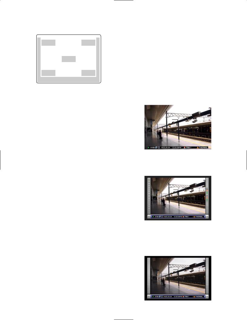
■On Monitor 2 (To display live or recorded images)
q |
|
q |
|
w |
|
w |
|
– |
q |
– |
|
B |
C |
||
|
|||
q |
|
q |
|
|
w – A |
|
The negative circled number q indicates the camera title default position.
Notes:
•The same images displayed on monitor 2 will be displayed on the VGA monitor.
•The camera title will be displayed with 16 characters (2 lines: 8 characters per line).
•When monitor 2 is selected, it is possible to switch the way of displaying the camera title in the following order by pressing the camera selection button 8 for the WJHD316A (the camera selection button 6 for the WJHD309A) while the shift function is on (by pressing the
SHIFT button):
Display the camera title → Display the camera title in list form → Not display the camera title
•When playing images recorded after selecting "ON" for "Embedded REC (Time & Date)", the embedded abbreviation of the recording mode (event recording/emergency recording) will be displayed.
The abbreviations are as follows: EVT: Pre-/post-event recording EMR: Emergency recording
•In case that "ON" is selected for "Embedded REC (Title)" and also "R-UPPER" or "R-LOWER" is selected for the camera title position, when playing images recorded with the resolution setting "SIF", a part of the embedded camera title may not be displayed.
Important:
•Since the VGA output from this unit is the same as for televisions (720 H x 480 V pixels/vertical frequency of 59.94 Hz), it may be possible that both the left and right edges can not fit onto the screen depending on the VGA monitor.
•It is impossible to use the MONITOR (VGA) connector when connecting the unit in the cascade connection.
•It may take time to display live images on the VGA monitor if the VGA monitor is turned on/off when the unit is running.
1.Camera Title
Displays the edited camera title.
A position to display the camera title can be selected from the following.
Upper left, upper right, lower left, lower right, center The default camera title position is upper right (R- UPPER).
2.Task Bar
Displays the current status.
The task bar consists of the main bar (w - A), the left bar (w - B), and the right bar (w - C).
There are 3 different ways to display the task bar as follows.
Mode 1
Displays only the main bar and the status is displayed on it.
Mode 2
Displays the status on the main bar, the left bar and the right bar.
Mode 3
Displays the status only on the main bar, and does not display information on the left bar and the right bar. Note: Mode 2 and Mode 3 are graphic operated. They
may not be as clear as Mode 1.
13
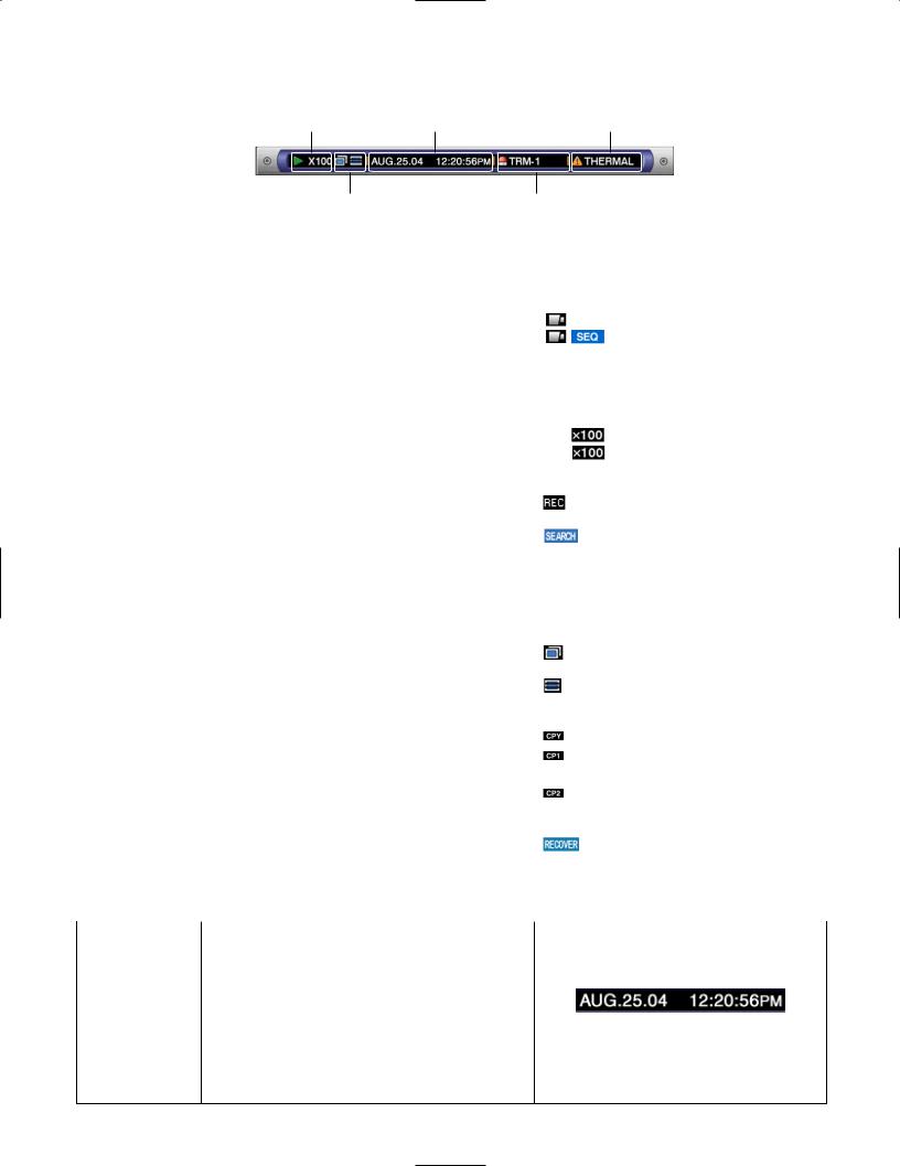
● Status on the Task Bar
• On the Main Bar
q Status Display Area |
e Live/Playback Time Display Area |
t Error Display Area |
|
w Copy/Delete Icons, Selected Disk, |
r Alarm Display Area |
|
|
|
|
|||||
|
Mirror/RAID Recovery Display Area |
|
|
|
|
|
|
|
|
|
|
q Status Display Area |
|
|
|
|
|
|
|
|
|
|
|
|
|
|
|
|
|
|
|
|
|
|
|
Indicated Item |
Status |
|
|
|
|
Indication |
|||||
|
|
|
|
|
|
|
|
|
|
|
|
Live |
Indicates the live image display status |
|
|
: Live image is displayed |
|||||||
|
|
|
|
||||||||
|
|
|
|
|
: Live images are displayed |
||||||
|
|
|
sequentially |
|
|
|
|
||||
|
|
|
|
|
|
|
|
|
|
||
Playback |
Indicates that playback is currently being performed |
5: Currently playing |
|
|
|
|
|||||
|
with the displayed playback speed |
|
4: Currently playing in reverse |
||||||||
|
|
|
h: Currently pausing |
|
|
|
|
||||
|
|
|
2 |
|
: Currently playing at fast speed |
||||||
|
|
|
1 |
|
: Currently playing in reverse at fast |
||||||
|
|
|
speed |
|
|
|
|
||||
|
|
|
|
|
|
|
|
|
|
|
|
Recording |
Indicates that recording is currently being performed |
|
: Currently recording |
|
|
|
|
||||
|
|
|
|
|
|
|
|
||||
|
|
|
|
|
|
|
|
|
|
|
|
Search |
Indicates that searching is currently being performed |
|
: Currently searching |
||||||||
|
|
|
|
||||||||
|
|
|
|
|
|
|
|
|
|
|
|
w Copy/Delete Icons, Selected Disk, Mirror/RAID Recovery Display Area |
|
|
|
|
|
|
|
|
|
||
|
|
|
|
|
|
|
|
|
|
|
|
Indicated Item |
Status |
|
|
|
|
Indication |
|||||
|
|
|
|
|
|
|
|
|
|
|
|
Copy |
Indicates that data copy is currently being performed |
|
: Currently copying |
|
|
|
|
||||
|
|
|
|
|
|
|
|
||||
|
|
|
|
|
|
|
|
|
|
|
|
Delete |
Indicates that data deletion is currently being |
per- |
: Currently deleting data |
||||||||
|
formed |
|
|||||||||
|
|
|
|
|
|
|
|
|
|
|
|
|
|
|
|
|
|
|
|
|
|
|
|
Selected Disk |
Indicates the selected disk |
|
|
: Currently the HDD copy area is selected |
|||||||
|
|
|
|
||||||||
|
|
|
|
: Currently the external recording device |
|||||||
|
|
|
|
connected to the COPY 1 port is selected |
|||||||
|
|
|
|
: Currently the external recording device |
|||||||
|
|
|
|
connected to the COPY 2 port is selected |
|||||||
|
|
|
|
|
|
|
|
|
|
|
|
RECOVER |
Indicates that mirror/RAID recovery is currently being |
|
: Currently recovering mirror/RAID |
||||||||
|
performed |
|
|
||||||||
|
|
|
|
|
|
|
|
|
|
|
|
|
|
|
|
|
|
|
|
|
|
|
|
e Live/Playback Time Display Area |
|
|
|
|
|
|
|
|
|
|
|
|
|
|
|
|
|
|
|
|
|
|
|
Indicated Item |
Status |
|
|
|
|
Indication |
|||||
|
|
|
|
|
|
|
|
|
|
|
|
Time |
Displays time and date of the displayed image |
|
|
|
|
|
|
|
|
|
|
|
When displaying live image: Current time and |
|
|
|
|
|
|
|
|
|
|
|
date |
|
|
|
|
|
|
|
|
|
|
|
When playing recorded image: Time and date |
|
|
|
|
|
|
|
|
|
|
|
|
|
|
|
|
|
|
|
|
||
|
when recorded |
|
|
|
|
|
|
|
|
|
|
|
|
|
|
|
|
|
|
|
|
|
|
|
|
|
|
|
Month:Day:Year |
Hour:Minute:Second |
|||||
*: During summer time, an asterisk (*) will be displayed on the left side of the displayed time.
14

r Alarm Display Area
Indicated Item |
Status |
|
|
|
Indication |
|
|
|
|
|
|
|
|
Alarm |
Indicates that an alarm has occurred |
|
|
|
|
|
|
VMD-*: When motion is detected |
|
|
|
|
|
|
LOSS-*: When video loss has occurred |
|
|
|
|
|
|
COM-#: When a command alarm has occurred |
|
|
|
|
|
|
TRM-#: When a terminal alarm has occurred |
|
|
|
|
|
|
|
|
Alarm type |
|||
|
|
|
|
|||
|
*: Camera number (1 - 16 for the WJ-HD316A, 1 - 9 |
|
|
|
|
|
|
for the WJ-HD309A) |
|
|
|
|
|
|
Alarm is occurring currently |
|||||
|
#: Alarm number |
|||||
|
|
|
|
|
|
|
|
|
|
|
|
|
|
Note: Refer to page 49 for further information about event types and event actions.
t Error Display Area
Indicated Item |
Status |
|
|
|
Indication |
|
|
||
|
|
|
|
|
|
|
|
|
|
Error Warning |
Indicates an error occurrence or warning |
|
|
|
|
|
|
|
|
|
ALT-*: Alteration is detected |
|
|
|
|
|
|
|
|
|
W-ERROR: Failed to write data on the HDD |
|
|
|
|
|
|
|
|
|
SMART: Warning of the HDD malfunction |
|
|
|
|
|
|
|
|
|
|
|
|
|
|
|
|
||
|
H-METER: Set time for hour-meter (active time of |
|
|
|
|
|
|
|
|
|
|
|
Error type |
|
|
||||
|
the HDD) warning has passed |
|
|
|
|
|
|
|
|
|
THERMAL: The temperature inside the unit is too |
|
|
|
|
|
|
|
|
|
high |
|
|
|
|
|
|
|
|
|
Error is occurring currently |
|
|
||||||
|
POWER: A power outage has been detected |
|
|
|
|||||
|
|
|
|
|
|
|
|
|
|
|
#-nn%: Warning about running out of disk space |
|
|
|
|
|
|
|
|
|
while displaying available disk space per- |
|
|
|
|
|
|
|
|
|
centage |
|
Abbreviation of partition |
|
|
||||
|
#-FULL: No available disk space |
|
|
|
|||||
|
|
|
|
|
|
|
|
|
|
|
Status |
Displayed |
|||||||
|
MEDIUM-n: An error occurred in an external |
|
|||||||
|
|
|
|
|
|
|
abbreviation |
||
|
recording device |
|
|
|
|
|
|
|
|
|
Normal recording area |
NML |
|||||||
|
REMOVE: The hard disk is removed from the sys- |
|
|||||||
|
|
|
|
|
|
|
|
|
|
|
Event recording area |
EVT |
|||||||
|
tem automatically because of an access error |
|
|||||||
|
|
|
|
|
|
|
|
|
|
|
Copy area |
CPY |
|||||||
|
FAN: The fan is faulty |
|
|||||||
|
|
|
|
|
|
|
|
|
|
|
External recording device |
|
|
||||||
|
HDD-ERROR: The hard disk designated as |
|
|
|
|||||
|
|
connected to the COPY1 port |
|
|
|||||
|
image storage was not found |
|
|
|
|||||
|
|
on the rear panel |
CP1 |
||||||
|
M-FAIL: Mirror recovery failed |
|
|
|
|
|
|
|
|
|
External recording device |
|
|
||||||
|
R-FAIL: RAID recovery failed |
|
connected to the COPY2 port |
|
|
||||
|
|
|
on the front panel |
CP2 |
|||||
|
*: Camera number (1 - 16 for the WJ-HD316A, 1 - 9 |
|
|
|
|
|
|
|
|
|
|
|
|
|
|
|
|
|
|
|
for the WJ-HD309A) |
|
|
|
|
|
|
|
|
|
#: Abbreviation that indicates partition |
|
|
|
|
|
|
|
|
|
nn: Available disk size |
|
|
|
|
|
|
|
|
|
n: Number of connector that an external recording |
|
|
|
|
|
|
|
|
|
device is connected to |
|
|
|
|
|
|
|
|
|
|
|
|
|
|
|
|
|
|
Notes:
•Refer to page 60 for further information about error types and what to do when an error has occurred.
•The RAID recovery is a function of the optional extension unit (WJ-HDE300 series). Refer to the Operating Instructions of the optional extension unit for further information about the RAID recovery.
15

• On the Left Bar
Indicated Item |
Status |
|
|
|
Indication |
|
|
|
|
|
|
Camera |
Indicates recording and displaying status |
|
|
|
|
|
Gray: Camera currently not displayed or not con- |
|
|
|
|
|
nected to the respective channel |
|
|
|
|
|
Green: Camera displayed on the monitor |
|
|
|
|
|
Orange: Camera currently being recorded |
|
|
|
|
|
Blue: Camera currently being recorded and dis- |
|
|
|
Camera 1 is on the top and camera |
|
played on the monitor |
|
|
|
|
|
|
|
|
||
|
|
|
|
16 is on the bottom |
|
|
|
|
|
|
|
|
|
|
|
|
|
• On the Right Bar
Indicated Item |
Status |
|
|
|
Indication |
|
|
|
|
|
|
Used disk space |
Indicates the available disk space of each partition. |
|
|
|
|
|
Top: 100 % of the disk space is being used (no |
|
|
|
|
|
available disk space) |
|
|
|
|
|
Second from the top: 80 % of the disk space is |
|
|
|
|
|
being used |
|
|
|
|
|
Center: 60 % of the disk space is being used |
|
|
|
|
|
Second from the bottom: 40 % of the disk space |
|
|
|
Normal Recording Area |
|
|
|
|
||
|
is being used |
|
|
|
|
|
|
|
|
||
|
Bottom: 20 % of the disk space is being used |
|
|
|
|
|
|
|
|
|
|
|
Note: When "CONTINUE" is selected on the "Disk End |
|
|
|
Event Recording Area |
|
Mode" page of the "Maintenance" setup menu, the |
|
|
|
|
|
|
|
|
|
|
|
available disk space will not be displayed. Refer |
|
|
|
|
|
|
|
|
|
|
|
to a system administrator for further information. |
|
|
|
|
|
NML: Available disk space of the normal record- |
|
|
|
|
|
ing area used for manual recording and |
|
|
|
|
|
schedule recording |
|
|
|
|
|
EVT: Available disk space of the event recording |
|
|
|
|
|
area used for event recording and emergency |
|
|
|
|
|
recording |
|
|
|
|
|
|
|
|
|
|
16

STARTUP
zInsert the power plug to an outlet (AC 120 V, 60 Hz)
Note: Make sure the power source is AC 120 V, 60 Hz.
Important:
When using the optional extension unit (WJ-HDE300 series), turn on the power of this unit after turning on the power of all extension units.
xTurn on the power switch on the rear panel.
The OPERATE indicator will light and the system check (checking the system and hard disk) will start.
The startup splash image below will be displayed on monitor 2 and the VGA monitor during the system check.
When the auto login is off, the login window will be displayed if any button on the front panel of this unit is pressed after the system check. (Go to step 3)
When the auto login is on, live images will be displayed after the system check.
Notes:
•If the hard disk configuration was changed after the last startup or the hard disk has problems, the HDD DISK MENU will be displayed automatically after the startup splash. (Refer to page 143 for further information.)
•It is possible to display the disk configuration menu by pressing the SET button when the image shown below, that says the system check has been completed, is displayed.
Important:
The startup splash window will not be displayed on monitor 1.
cEnter a user name and password.
Rotate the jog dial to select a character to be entered in the cursor position.
It is also possible to enter numbers by pressing the camera selection buttons ([1] - [10/0] for the WJ-HD316A, [1] - [9], [0] for the WJ-HD309A).
To move the cursor, press the arrow buttons.
Use the same method to enter or edit characters attached to images. Refer to page 59 for further information.
Notes:
•The default user name and password are as follows:
User name: ADMIN Password: 12345
•To enhance the security, change the password for an administrator before starting to run the unit. It is recommended to change the password for an administrator periodically.
•To log out, press the LOGOUT button after confirming that the SHIFT indicator is lit.
vDisplay a live image.
Press the SET button to display a live image.
If the authentication (login) window is displayed, enter the user name and password.
When authenticated, a live image will be displayed.
When not authenticated, the authentication (login) window will be displayed again.
17
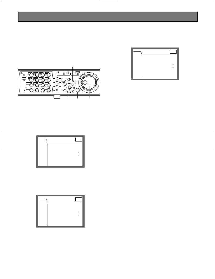
CLOCK ADJUSTMENT
It is recommended to check the clock periodically and put the clock right if it shows the wrong time.
Adjust the clock when displaying a live image.
Note: The following are the descriptions of how to adjust the clock on the SETUP MENU (Quick). Refer to page 106 for descriptions of how to adjust the clock on the SETUP MENU (Advanced).
|
|
|
|
|
|
zv |
|
MONITOR1 |
|
|
|
|
STOP |
PLAY PAUSE REC - REC STOP |
|
|
|
|
|
|
|
|
|
MONITOR2 |
2 |
3 |
4 |
|
|
REV |
FWD |
1 |
PAN/ |
GOTO |
|
|
|||
|
|
|
|
SEARCH |
|
||
SHIFT |
|
SEQ |
OSD |
TILT |
LAST |
|
|
|
|
PAN/TILT |
SETUP |
|
|||
5 |
6 |
7 |
8 |
|
|
||
ZOOM/ |
A-B SLOW |
/ESC |
|
||||
|
|
|
|
FOCUS |
REPEAT |
– |
+ |
DISK SELECT |
COPY |
TEXT |
MARK |
|
|
||
|
|
|
|
||||
9 |
10/0 |
11 |
12 |
IRIS |
LISTED |
|
|
EL-ZOOM |
|
LOGOUT |
LOGOUT |
PRESET |
|
|
|
|
/AUTO |
|
|
|
|||
13 |
14 |
15 |
16 |
|
SET |
|
|
|
|
|
|||||
|
|
|
|
|
BUSY |
|
|
xc c x
zPress the SETUP/ESC button for 2 seconds or more.
The SETUP MENU (Quick) will be displayed on monitor 2 and the VGA monitor.
SETUP MENU |
LIVE |
|
Quick |
||
|
Display |
■ Date Format |
|
MMM.DD.YY |
|||||||||||||
|
■ Time Format |
|
12h |
|||||||||||||
REC & Event |
||||||||||||||||
|
||||||||||||||||
|
■ Time & Date |
|
|
|
||||||||||||
Network |
|
PM |
||||||||||||||
|
JAN |
. |
1 |
. |
04 |
|
10 |
: |
00 |
: |
00 |
|
||||
|
|
|
|
|||||||||||||
|
|
|
|
|
|
|
|
|
|
|
|
|
|
SET |
|
|
|
■ Time & Date Display Position |
|
L-UPPER |
|||||||||||||
|
■ Camera Title |
|
SETUP |
|
||||||||||||
|
■ Camera Title Display Position |
|
R-LOWER |
|||||||||||||
|
■ Live Sequence |
|
SETUP |
|
||||||||||||
|
■ Summer Time (Day Light Savings) |
|
|
|||||||||||||
|
|
AUTO |
||||||||||||||
|
■ Beep (Operation) |
|
ON |
|||||||||||||
|
■ Language |
|
ENGLISH |
|||||||||||||
|
|
|
|
|
|
|
|
|
|
|
|
|
|
|
|
|
Advanced Menu |
|
|
|
|
|
|
|
|
|
|
|
|
|
|
|
|
xMove the cursor to "Time & Date" using the arrows button (C D A B), and set the time
(Month, Day, Year, Time) using the jog dial.
SETUP MENU |
LIVE |
|
Quick |
||
|
Display |
■ Date Format |
|
MMM.DD.YY |
|||||||||||||
|
■ Time Format |
|
12h |
|||||||||||||
REC & Event |
||||||||||||||||
|
||||||||||||||||
|
■ Time & Date |
|
|
|
||||||||||||
Network |
|
PM |
||||||||||||||
|
JAN |
. |
1 |
. |
04 |
|
10 |
: |
00 |
: |
00 |
|
||||
|
|
|
|
|||||||||||||
|
|
|
|
|
|
|
|
|
|
|
|
|
|
SET |
|
|
|
■ Time & Date Display Position |
|
L-UPPER |
|||||||||||||
|
■ Camera Title |
|
SETUP |
|
||||||||||||
|
■ Camera Title Display Position |
|
R-LOWER |
|||||||||||||
|
■ Live Sequence |
|
SETUP |
|
||||||||||||
|
■ Summer Time (Day Light Savings) |
|
|
|||||||||||||
|
|
AUTO |
||||||||||||||
|
■ Beep (Operation) |
|
ON |
|||||||||||||
|
■ Language |
|
ENGLISH |
|||||||||||||
|
|
|
|
|
|
|
|
|
|
|
|
|
|
|
|
|
Advanced Menu |
|
|
|
|
|
|
|
|
|
|
|
|
|
|
|
|
cMove the cursor to "SET" and press the SET button.
The set time will be applied.
SETUP MENU |
LIVE |
|
Quick |
||
|
Display |
■ Date Format |
|
MMM.DD.YY |
|||||||||||||
|
■ Time Format |
|
12h |
|||||||||||||
REC & Event |
||||||||||||||||
|
||||||||||||||||
|
■ Time & Date |
|
|
|
||||||||||||
Network |
|
|
|
|
|
|
|
|
: |
|
: |
|
|
PM |
||
|
JAN |
. |
1 |
. |
04 |
|
10 |
00 |
00 |
|
||||||
|
|
|
|
|||||||||||||
|
|
|
|
|
|
|
|
|
|
|
|
|
|
SET |
|
|
|
■ Time & Date Display Position |
|
L-UPPER |
|||||||||||||
|
■ Camera Title |
|
SETUP |
|
||||||||||||
|
■ Camera Title Display Position |
|
R-LOWER |
|||||||||||||
|
■ Live Sequence |
|
SETUP |
|
||||||||||||
|
■ Summer Time (Day Light Savings) |
|
|
|||||||||||||
|
|
AUTO |
||||||||||||||
|
■ Beep (Operation) |
|
ON |
|||||||||||||
|
■ Language |
|
ENGLISH |
|||||||||||||
|
|
|
|
|
|
|
|
|
|
|
|
|
|
|
|
|
Advanced Menu |
|
|
|
|
|
|
|
|
|
|
|
|
|
|
|
|
vPress the SETUP/ESC button for 2 seconds or more.
The SETUP MENU (Quick) will disappear and a live image will be displayed.
Important:
Recording will stop for around 4 seconds just after setting the clock.
18

SHUTDOWN
To shutdown the unit, do the following.
When recording is being performed, press the REC button for 2 or more seconds. Recording will stop and the indicator on the REC button will go off.
When playback is being performed, press the STOP button. Playback will stop and the indicator on the PLAY/PAUSE button will go off.
Turn off the power of the unit after confirming that the HDD1 and HDD2 indicators are off.
Important:
•Detach the plug from the outlet if not operating the unit for a length of time.
•When the unit has not been used for a certain period, turn on the power of the unit (approximately once a week), and perform recording/playback to prevent interferences with functions.
19
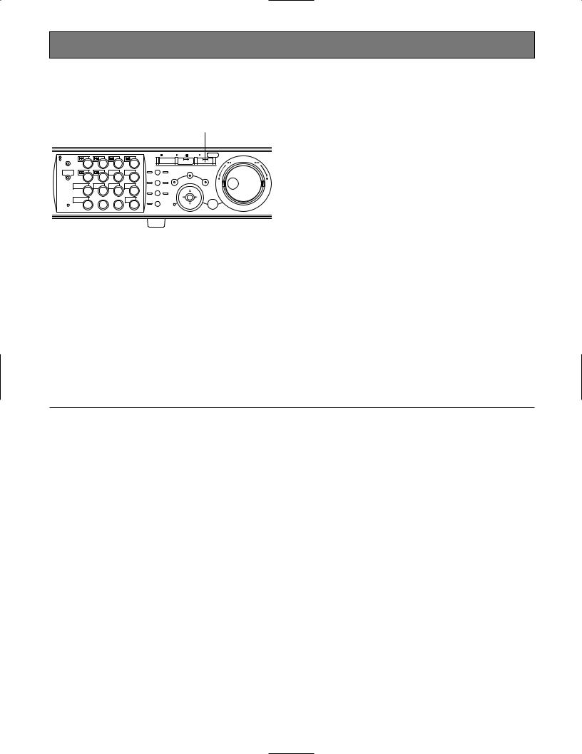
RECORDING (Manual Recording)
Do the following to record manually.
Refer to a system administrator about the required settings for manual recording.
|
|
|
|
|
|
|
zx |
|
|
MONITOR1 |
|
|
|
|
STOP |
PLAY PAUSE REC - REC STOP |
|
R |
MONITOR2 |
|
|
|
|
|
REV |
FWD |
1 |
2 |
3 |
4 |
|
|
|
|
|
|
PAN/ |
GOTO |
|
|
||||
R |
|
|
|
|
SEARCH |
|
||
SHIFT |
|
SEQ |
OSD |
TILT |
LAST |
|
||
|
|
|
PAN/TILT |
SETUP |
|
|||
|
5 |
6 |
7 |
8 |
ZOOM/ |
A-B SLOW |
/ESC |
|
|
|
|
|
|
FOCUS |
REPEAT |
– |
+ |
|
DISK SELECT |
COPY |
TEXT |
MARK |
|
|
||
|
|
|
|
|
||||
|
9 |
10/0 |
11 |
12 |
IRIS |
LISTED |
|
|
|
EL-ZOOM |
|
LOGOUT |
LOGOUT |
PRESET |
|
|
|
|
|
/AUTO |
|
|
|
|||
2 |
13 |
14 |
15 |
16 |
|
SET |
|
|
|
BUSY |
|
||||||
|
|
|
|
|
|
|
|
zStart recording.
Press the REC button to start recording.
The indicator on the button will light and recording will start. Images from all the connected cameras will be recorded with the default setting.
It is possible to record only images displayed on monitor 2 and the VGA monitor by changing the settings.
When recording with higher priority than manual recording is performed, manual recording will not be performed until this recording finishes.
Refer to the following about the recording mode.
xStop recording.
Press the REC button down for around 2 seconds.
The indicator on the button will go off and recording will stop.
Notes:
•The camera selection button will light orange (currently recording) or blue (currently being recorded and displayed on the monitor) to indicate which camera is being recorded.
•When recording with other recording modes being performed, the indicator on the REC button will not go off even though the REC button is pressed to stop manual recording.
•Manual recording will be stopped for a camera channel when the supply of the video input signals to the camera channel is stopped. When the supply of the video input signals to the camera channel is resumed, manual recording will be performed automatically.
● Recording Mode and Priority
There are 4 recording modes as follows.
Recording Mode |
Description |
Priority*1 |
Emergency Recording |
Start recording manually using an external switch at an emergency event occurrence |
Highest |
Event Recording |
Recording will be performed automatically at an event occurrence |
1*2 |
Manual Recording |
Start and stop recording manually |
2*2 |
Schedule Recording |
Recording will be performed automatically with a designated start/stop time and date |
3*2 |
*1: Priorities on the above table are the default settings. (Emergency recording is the highest priority.)
*2: Priorities for manual recording, schedule recording and event recording can be changed. Refer to a system administrator about the settings.
20
RECORDING (Emergency Recording)
Record manually using an external switch at an emergency event occurrence.
For example, install an external switch at the reception counter, and start recording with it when a suspicious individual appears.
Refer to a system administrator about the required settings for emergency recording.
External switch
|
|
|
|
|
|
|
|
|
z |
|
|
MONITOR1 |
|
|
|
|
STOP |
PLAY PAUSE REC - REC STOP |
|
|
|
|
|
|
|
|
|
|
|
|
TIMER |
MONITOR2 |
|
|
|
|
|
|
RE |
|
1 |
2 |
3 |
4 |
|
|
|
|
|
|
|
PAN/ |
GOTO |
|
|
||||
ALARM |
ERROR |
|
|
|
|
|
SEARCH |
||
SHIFT |
|
SEQ |
OSD |
TILT |
LAST |
|
|||
|
|
|
|
|
PAN/TILT |
SETUP |
|||
|
|
5 |
6 |
7 |
8 |
|
|
||
ALARM |
|
ZOOM/ |
A-B |
SLOW |
/ESC |
||||
|
|
|
|||||||
SUSPEND |
ALARM |
|
|
|
|
FOCUS |
REPEAT |
|
– |
|
RESET |
DISK SELECT |
COPY |
TEXT |
MARK |
|
|
|
|
|
|
9 |
10/0 |
11 |
12 |
IRIS |
LISTED |
|
|
OPERATE |
HDD 1 |
EL-ZOOM |
|
LOGOUT |
LOGOUT |
PRESET |
|
|
|
|
|
/AUTO |
|
|
|
||||
|
HDD 2 |
13 |
14 |
15 |
16 |
|
|
SET |
|
|
|
|
BUSY |
||||||
|
|
|
|
|
|
|
|
|
|
x
zPress the external switch.
The indicator on the REC button will light and recording will start.
With the default setting, recording will be performed for 10 seconds.
Emergency recording is the highest priority. Emergency recording will be performed even when this unit is recording in other recording modes.
xStop recording.
When the recording duration set in advance has passed, recording will stop automatically.
With the default setting, recording will stop automatically after recording for 10 seconds.
When "CONTINUE" is selected for "Recording Time" of "Emergency REC" on the SETUP MENU (Recording), press the ALARM RESET button to stop recording.
The indicator on the REC button will go off and recording will stop.
Notes:
•The camera selection button will light orange (currently recording) or blue (currently being recorded and displayed on the monitor) to indicate which camera is being recorded.
•When starting emergency recording while another recording with a different recording mode (except event recording) is being performed, the indicator on the REC button will remain lit and the other recording will resume after the emergency recording has finished.
●Recording duration of emergency recording
Recording duration of emergency recording can be set as follows. Refer to a system administrator for further information.
Parameter |
Recording Duration |
1 s - 10 s |
Record for the selected time (1 - 10 sec- |
|
onds, can be set in 1 second intervals) |
|
|
20 s |
Record for 20 seconds |
30 s |
Record for 30 seconds |
1 min - 10 min |
Record for the selected time (1 -10 min- |
|
utes can be set in 1 minute intervals) |
|
|
20 min - 60 min |
Record for the selected time (20 - 60 min- |
|
utes, can be set in 10 minutes intervals) |
|
|
MANUAL |
Record only while the external switch is |
|
being pressed down |
|
(Record for at least 8 seconds) |
|
|
CONTINUE |
Record until the ALARM RESET button is |
|
pressed |
|
|
21
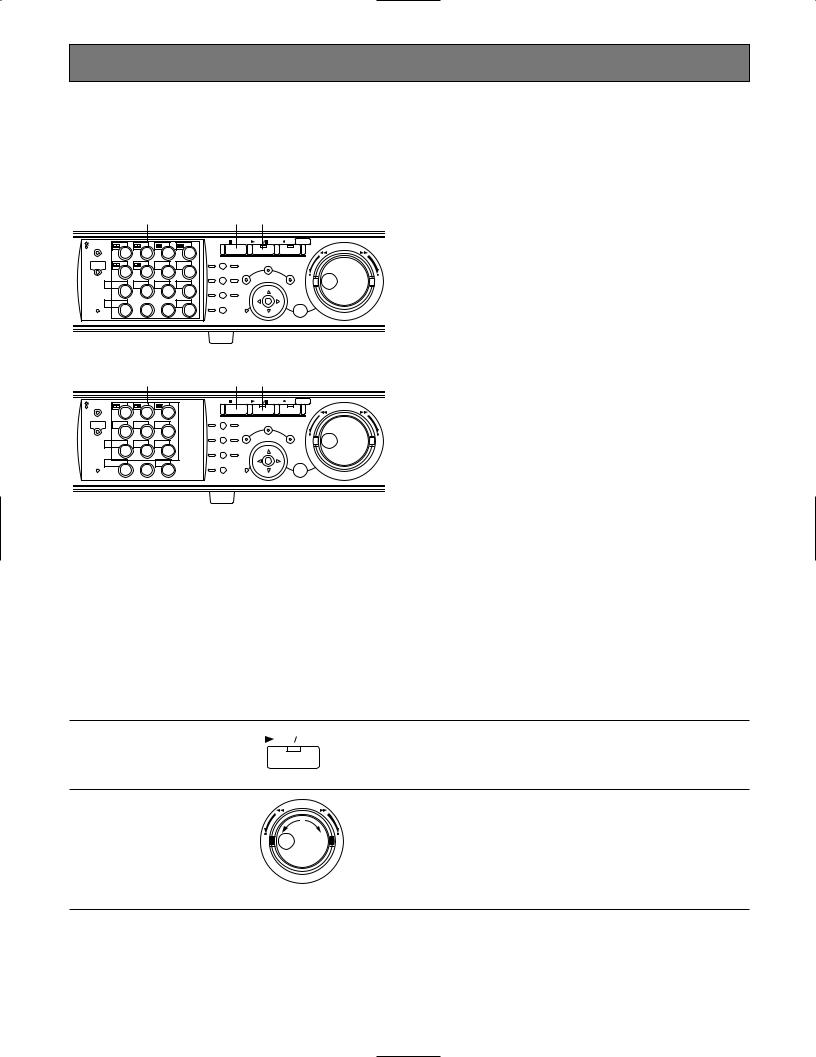
PLAYBACK
It is possible to play recorded images without stopping recording.
The playback images will be displayed on monitor 2 and the VGA monitor.
[WJ-HD316A]
zc x
|
MONITOR1 |
|
|
|
|
STOP |
PLAY PAUSE REC - REC STOP |
|
|
MONITOR2 |
|
|
|
|
|
REV |
FWD |
R |
1 |
2 |
3 |
4 |
|
|
|
|
|
PAN/ |
GOTO |
|
|
||||
R |
|
|
|
|
|
|
||
SHIFT |
|
SEQ |
OSD |
TILT |
LAST |
SEARCH |
|
|
|
|
|
||||||
|
|
|
PAN/TILT |
SETUP |
|
|||
|
5 |
6 |
7 |
8 |
|
|
||
|
ZOOM/ |
A-B SLOW |
/ESC |
+ |
||||
|
|
|
|
|
FOCUS |
REPEAT |
– |
|
|
DISK SELECT |
COPY |
TEXT |
MARK |
|
|
|
|
|
9 |
10/0 |
11 |
12 |
IRIS |
LISTED |
|
|
|
EL-ZOOM |
|
|
LOGOUT |
PRESET |
|
|
|
2 |
13 |
14 |
15 |
16 |
/AUTO |
|
SET |
|
|
BUSY |
|
||||||
|
|
|
|
|
|
|
|
[WJ-HD309A]
zc x
MONITOR1 |
|
|
|
STOP |
PLAY PAUSE |
REC - REC STOP |
|
|
MONITOR2 |
|
|
|
|
|
REV |
FWD |
|
R |
1 |
2 |
3 |
|
|
|
||
|
|
|
|
|
||||
|
PAN/ |
GOTO |
|
|
|
|||
R |
|
|
|
|
|
|
||
|
|
|
TILT |
LAST |
SEARCH |
|
|
|
SHIFT |
SEQ |
TEXT |
OSD |
|
|
|||
|
PAN/TILT |
|
SETUP |
|
||||
|
4 |
5 |
6 |
|
|
|
||
|
ZOOM/ |
A-B SLOW |
|
/ESC |
+ |
|||
|
|
|
|
FOCUS |
REPEAT |
|
– |
|
|
DISK SELECT |
COPY |
MARK |
|
|
|
|
|
|
7 |
8 |
9 |
IRIS |
LISTED |
|
|
|
|
EL-ZOOM |
|
LOGOUT |
PRESET |
|
|
|
|
2 |
|
0 |
|
/AUTO |
|
|
SET |
|
|
|
|
|
|
|
|||
BUSY
zSelect the camera respective to the recorded images to be played. (Go to step 2 if not necessary)
Press the desired camera selection button.
The pressed camera selection button will light green or blue and the respective live images will be displayed.
xStart playback.
Press the PLAY/PAUSE button.
The indicator on the PLAY/PAUSE button will light and the recorded images of the selected camera will be played.
First playback after login: The latest recorded image will be played.
With the default setting, playback will start 5 seconds before the start time of the latest recorded image. The start time can be selected from the following:
5 s/10 s/30 s/1 min/5 min
Refer to a system administrator about the settings.
Other than those above: Playback will start from the end point of the recorded image played last time.
cStop playback.
Press the STOP button.
The indicator on the PLAY/PAUSE button will go off and playback will be stopped.
Live images will be displayed on monitor 2 and the VGA monitor.
● Available functions during playback
Pause |
|
|
Pressing the PLAY/PAUSE button to pause playback. While pausing, |
|
PLAY |
|
PAUSE |
the indicator on the PLAY/PAUSE button will blink. |
|
|
|
|
|
|
|
|
|
|
|
|
|
|
|
Pressing this button again will resume playback. |
Single frame skip
REV FWD |
|
Rotating the jog dial during pause will skip to the next or previous |
|
|
frame. |
– |
+ |
Rotating the jog dial clockwise will skip to the next frame and rotating |
|
|
it counterclockwise will skip to the previous frame. |
22

Fast forward/Fast reverse |
|
|
|
Rotating the shuttle ring will change the playback speed (1/2x, 1x, 2x, |
|
|
|
|
5x, 10x, 20x) according to rotated degree. When the shuttle ring is |
REV |
FWD |
|
|
held in the 20x position (rotated to the end) for 5 seconds, the play- |
|
|
|
|
back speed will be 50x. When the shuttle ring is held 5 more seconds |
– |
|
|
+ |
after the playback speed became 50x, the playback speed will be |
|
|
|||
|
|
|
|
|
|
|
|
|
100x. |
|
|
|
|
Rotating the shuttle ring clockwise will play images at a faster speed |
|
|
|
|
and rotating it counterclockwise will play images in reverse at a faster |
|
|
|
|
speed. |
|
|
|
|
To play at normal speed, release the shuttle ring. |
|
|
|
|
|
Hold playback speed |
|
|
|
Press the SET button while holding the rotated shuttle ring to hold a |
REV |
FWD |
|
|
desired playback speed. (Playback speed will be held even though |
|
|
|
|
|
– |
|
|
+ |
the shuttle ring is released.) |
|
|
To return to the normal playback speed, press the SET button. |
||
|
|
|
|
|
|
|
|
|
|
+ |
SET |
|
Skip |
|
REV |
FWD |
– |
+ |
Play the latest recorded image
PAN/ |
GOTO |
TILT |
LAST |
Multi-screen display |
|
|
|
(For the WJ-HD316A) |
SHIFT |
+ |
1 |
|
|
··· |
|
|
|
|
|
|
SHIFT |
+ |
6 |
|
|
||
|
|
|
|
(For the WJ-HD309A) |
SHIFT |
+ |
1 |
|
|
··· |
|
|
|
|
SHIFT |
+ |
3 |
|
||
|
|
Rotating the jog dial during playback will skip to the next or previous recorded image.
Rotating the jog dial clockwise will skip to the start time of the next recording and start playback, and rotating it counterclockwise will skip to the start time of the previous one. (Rotating the jog dial counterclockwise at a point shortly after the start time of the recording will skip to the start time of the previous recording).
If there is no next or previous recorded image, current playback will continue.
Press the GO TO LAST button to play the latest recorded image. When the GO TO LAST button is pressed for 2 seconds or more while displaying live images, playback of the latest recorded images will start.
When the GO TO LAST button is pressed during recoding, it may happen that playback starts from not the latest recording time.
It is possible to display recorded images in multi-screen format (4/7/9/10/13/16 for the WJ-HD316A, 4/7/9 for the WJ-HD309A). q Press the SHIFT button. The SHIFT indicator will light.
wPress a camera selection button (1 - 6 for the WJ-HD316A, 1 - 3 for the WJ-HD309A) to select a desired multi-screen.
Camera selection button 1: 4-split screen Camera selection button 2: 7-split screen Camera selection button 3: 9-split screen
Camera selection button 4: 16-split screen (Only for the WJHD316A)
Camera selection button 5: 10-split screen (Only for the WJHD316A)
Camera selection button 6: 13-split screen (Only for the WJHD316A)
eTo display recorded images on a single screen, press the SHIFT button again.
After the SHIFT indicator goes off, press the camera selection button.
23
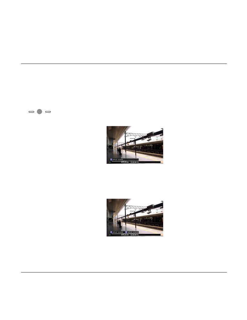
Marking
(For the WJ-HD316A)
(For the WJ-HD309A)
SHIFT
SHIFT
|
|
|
It is possible to play from a marked point. Do the following to mark a desired |
|
|
|
|
point. |
|
+ |
|
1. Press the SHIFT button. The SHIFT indicator will light. |
||
MARK |
|
|||
12 |
2. Press the camera selection button 12 (9 for the WJ-HD309A) (MARK) at a |
|||
|
||||
|
|
|
desired point to be marked during playback. |
|
+ |
MARK |
|
Up to 100 points can be marked. When more than 100 points are marked, |
|
|
9 |
the older marked points will be overwritten by the newer marked points. In |
||
|
|
|
this case, the oldest marked point is the first to be overwritten. |
|
|
|
|
When marked while displaying in multi-screen, the same number of split |
|
|
|
|
screens will be counted as marked points. (When a point is marked while |
|
|
|
|
displaying a 16-split screen, 16 points will be marked simultaneously.) |
|
Text display |
|
|
|
|
|
|
It is possible to display text information attached to a recorded image during |
|
|
|
|
+ |
|
playback. |
|
(For the WJ-HD316A) |
SHIFT |
TEXT |
|
||||
|
11 |
Text display is available only when playing on a single screen. |
|||||
|
|
|
|
|
|||
|
|
|
|
|
|
|
q Pause playback. |
(For the WJ-HD309A) |
SHIFT |
+ |
TEXT |
|
w Press the SHIFT button. The SHIFT indicator will light. |
||
|
5 |
||||||
|
|
|
|
|
e Press the camera selection button 11 (5 for the WJ-HD309A) (TEXT). |
||
|
|
|
|
|
|
|
|
|
|
|
|
|
|
|
|
A - B repeat playback |
|
|
|
|
It is possible to play recorded images between two designated points repeat- |
||
|
|
|
|
|
|
|
edly. |
ZOOM/ |
A-B |
|
|
|
|
q Designate a start point (A) by pressing the A - B REPEAT button during |
|
FOCUS |
REPEAT |
|
|
|
|
playback. |
|
|
|
|
|
|
|
|
|
|
|
|
|
|
|
|
The A - B REPEAT indicator will light, and the time of point A will be dis- |
|
|
|
|
|
|
|
played. |
Blink: During the A-B repeat playback |
|
|
|||||
|
|
|
|||||
Light: When designating a start point (A)


 Time of point A
To cancel the designated point, press the SETUP/ESC button.
wDesignate an end point (B) by pressing the A - B REPEAT button during playback.
When the start point and the end point are set, the A - B REPEAT indicator will start blinking.
Playback between point A and B will start and keep playing repeatedly. The time of point A and B will be displayed during playback.

 Time of point A and B
ePress the A - B REPEAT button during A - B repeat playback to return to normal playback.
Note: When the clock of the unit has been changed by editing the time and date settings or by the auto time adjustment function, overlapping of the time ranges of the images recorded before and after the time adjustment could occur.
In this case, the A-B repeat playback may not function properly.
Notes:
•Playback will be paused if the playback time caught up with the recording time (present time) when recording and playback are performed simultaneously.
•When playing images recorded at a high recording rate, unsteady playback speed and audio break-up may occur.
•A black screen may sometimes be displayed during fast playback/fast reverse playback. This is a normal operation.
24
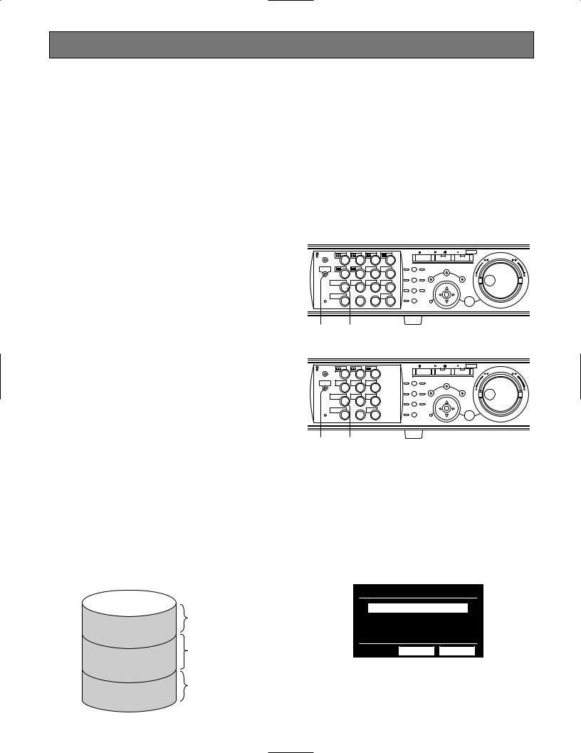
PLAYBACK IMAGE ON A DESIGNATED DISK
Images from a camera will be recorded on the built-in hard disk or external recording devices (DVD-RAM drive, DVD-R drive or CD-R drive) connected to this unit.
Available disk areas are as follows.
Note: External recording devices can be used as a copy area for images recorded on the hard disk. It is impossible to record images on the external recording devices directly.
HDD Normal Recording Area/Event Recording Area:
Recording area in the built-in hard disk of this unit. Recorded images by manual recording (page 20) or event recording will be stored in this area. There are 3 ways to search for a recorded image and play it when "HDD normal area" or "event recording area" is selected as the recording area.
•Search for a recording event and play it (Recording event search) (page 28)
•Search for a motion detected time and date from the recorded images and play it (VMD search) (page 36)
•Search for a marked point and play it (Marking search) (page 41)
HDD Copy Area: Recording area in the built-in hard disk of this unit. Recorded images will be copied in this area. There are 2 ways to search for a recorded image and play it when "HDD copy area" is selected as the recording area.
•Search for a recording event and play it (Recording event search) (page 28)
•Search for a motion detected time and date from the recorded images and play it (VMD search) (page 36)
COPY 1/COPY 2: Recording area in the external recording device (DVD-RAM disk, DVD-R disk, CD-R disk) connected to the COPY 1 port or the COPY 2 port of the unit. Recorded images will be copied in this area.
To search for a recorded image and play it when "COPY 1" or "COPY 2" is selected as the recording area.
•Search for copy data and play it back (Copy Data Search) (page 32)
Built-in hard disk |
|
|
|
Recording area for |
|
|
manual recording |
|
Normal recording area |
and schedule |
|
recording |
||
|
Recording area for |
|
|
event recording |
|
Event recording area |
and emergency |
|
recording |
||
|
||
|
Recording area for |
|
Copy area |
copying |
|
|
Notes:
•Playback images will be displayed only on monitor 2 and the VGA monitor.
•Playback can be performed during recording.
•When a pre-recording area is created in an optional extension unit, it is possible to play the images recorded on the pre-recording area.
•Disk space size of each recording area differs depending on the settings.
Refer to a system administrator for further information.
[WJ-HD316A]
|
MONITOR1 |
|
|
|
|
STOP |
PLAY PAUSE REC - REC STOP |
|
|
MONITOR2 |
|
|
|
|
|
REV |
FWD |
R |
1 |
2 |
3 |
4 |
|
|
||
|
|
|
|
|||||
|
PAN/ |
GOTO |
|
|
||||
R |
|
|
|
|
|
|
||
SHIFT |
|
SEQ |
OSD |
TILT |
LAST |
SEARCH |
|
|
|
|
|
||||||
|
|
|
PAN/TILT |
SETUP |
|
|||
|
5 |
6 |
7 |
8 |
|
|
||
|
ZOOM/ |
A-B SLOW |
/ESC |
+ |
||||
|
|
|
|
|
FOCUS |
REPEAT |
– |
|
|
DISK SELECT |
COPY |
TEXT |
MARK |
|
|
|
|
|
9 |
10/0 |
11 |
12 |
IRIS |
LISTED |
|
|
|
EL-ZOOM |
|
|
LOGOUT |
PRESET |
|
|
|
2 |
13 |
14 |
15 |
16 |
/AUTO |
|
SET |
|
|
|
|
BUSY
zx
[WJ-HD309A]
MONITOR1 |
|
|
|
STOP |
PLAY PAUSE |
REC - REC STOP |
|
|
MONITOR2 |
|
|
|
|
|
REV |
FWD |
|
R |
1 |
2 |
3 |
|
|
|
|
|
|
PAN/ |
GOTO |
|
|
|
|||
R |
|
|
|
|
|
|
||
|
|
|
TILT |
LAST |
SEARCH |
|
|
|
SHIFT |
SEQ |
TEXT |
OSD |
|
|
|||
|
PAN/TILT |
|
SETUP |
|
||||
|
4 |
5 |
6 |
|
|
|
||
|
ZOOM/ |
A-B SLOW |
|
/ESC |
+ |
|||
|
|
|
|
FOCUS |
REPEAT |
|
– |
|
|
DISK SELECT |
COPY |
MARK |
|
|
|
|
|
|
7 |
8 |
9 |
IRIS |
LISTED |
|
|
|
|
EL-ZOOM |
|
LOGOUT |
PRESET |
|
|
|
|
2 |
|
0 |
|
/AUTO |
|
|
SET |
|
|
|
|
|
|
|
|||
BUSY
zx
zPress the SHIFT button.
The SHIFT indicator will light.
xPress the camera selection button 9 (7 for the WJ-HD309A) (DISK SELECT).
The DISK SELECT window will be displayed on monitor 2 and the VGA monitor.
DISK SELECT
 HDD NORMAL/EVENT AREA
 HDD COPY AREA
 COPY 1
 COPY 2
OK CANCEL
25
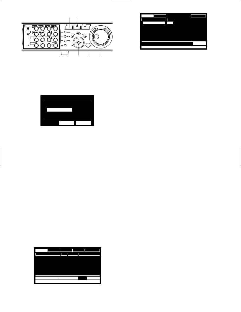
n b
|
MONITOR1 |
|
|
|
|
STOP |
PLAY PAUSE REC - REC STOP |
|
R |
MONITOR2 |
|
|
|
|
|
REV |
FWD |
1 |
2 |
3 |
4 |
|
|
|
|
|
|
PAN/ |
GOTO |
|
|
||||
R |
|
|
|
|
SEARCH |
|
||
SHIFT |
|
SEQ |
OSD |
TILT |
LAST |
|
||
|
|
|
PAN/TILT |
SETUP |
|
|||
|
5 |
6 |
7 |
8 |
|
|
||
|
ZOOM/ |
A-B SLOW |
/ESC |
|
||||
|
|
|
|
|
FOCUS |
REPEAT |
– |
+ |
|
DISK SELECT |
COPY |
TEXT |
MARK |
|
|
||
|
|
|
|
|
||||
|
9 |
10/0 |
11 |
12 |
IRIS |
LISTED |
|
|
|
EL-ZOOM |
|
LOGOUT |
LOGOUT |
PRESET |
|
|
|
|
|
/AUTO |
|
|
|
|||
2 |
13 |
14 |
15 |
16 |
|
SET |
|
|
|
BUSY |
|
||||||
|
|
|
|
|
|
|
|
c c cv
cSelect a disk to be played using the jog dial and move the cursor to "OK" using the arrows button. Press the SET button to determine the selection.
DISK SELECT
 HDD NORMAL/EVENT AREA
 HDD COPY AREA
 COPY 1
 COPY 2
OK CANCEL
When "HDD NORMAL/EVENT AREA" or "HDD COPY AREA" is selected, the recording event list window will be displayed. (Refer to page 28 for further information about the recording event list window.)
When "COPY 1" or "COPY 2" is selected, the copy data list window will be displayed. (Refer to page 32 for further information about the copy data list window.)
To close the DISK SELECT window, move the cursor to select "CANCEL" and press the SET button.
Important:
In the following cases, the recording event list window/copy data list window will not be displayed even when you move the cursor to "OK" and press the SET button after selecting any of "HDD COPY AREA", "COPY 1" or "COPY 2":
•When another user has selected the same area
•When copying is being performed manually in the same area using a PC via a network
vRotate the jog dial to select a desired recorded image to be played.
TIME&DATE CAMERA |
REC EVENT |
TEXT |
UNLOCK FILTER |
||
TIME&DATE |
CAM |
REC EVT |
|
TEXT |
|
AUG.20.04 3:04:23 PM |
01ch |
MANUAL |
ABCDEFGHIJ |
||
AUG.20.04 3:01:24 PM |
01ch |
MANUAL |
ABCDEFGHIJ |
||
AUG.20.04 3:00:40 PM |
01ch |
MANUAL |
ABCDEFGHIJ |
||
AUG.20.04 3:00:00 PM |
01ch |
MANUAL |
ABCDEFGHIJ |
||
AUG.20.04 2:59:11 PM |
01ch |
MANUAL |
ABCDEFGHIJ |
||
AUG.20.04 2:45:45 PM |
01ch |
MANUAL |
ABCDEFGHIJ |
||
AUG.20.04 2:44:09 PM |
01ch |
MANUAL |
ABCDEFGHIJ |
||
AUG.20.04 2:33:16 PM |
01ch |
MANUAL |
ABCDEFGHIJ |
||
AUG.20.04 3:22:10 AM AUG.20.04 2:31:18 AM |
TOTAL |
100 |
|||
TIME&DATE  SEARCH
  REC EVENT
  SEARCH
  VMD
VMD  SEARCH
  MARK
MARK
TIME&DATE CAMERA |
REC EVENT |
TEXT |
UNLOCK FILTER |
||
TIME&DATE |
CAM |
REC EVT |
|
TEXT |
|
AUG.20.04 3:00:00 PM |
01ch |
MANUAL |
ABCDEFGHIJ |
||
AUG.19.04 2:29:00 PM |
01ch |
MANUAL |
ABCDEFGHIJ |
||
|
|
MANUAL |
ABCDEFGHIJ |
||
|
|
MANUAL |
ABCDEFGHIJ |
||
|
|
MANUAL |
ABCDEFGHIJ |
||
|
|
MANUAL |
ABCDEFGHIJ |
||
|
|
MANUAL |
ABCDEFGHIJ |
||
|
|
MANUAL |
ABCDEFGHIJ |
||
|
|
|
|
TOTAL |
-- |
|
COPY DATA |
|
|
|
|
bPress the PLAY/PAUSE button to play the selected recorded image.
The indicator on the PLAY/PAUSE button will light and playback will start.
Notes:
•When "COPY 1" or "COPY 2" is selected, audio will not be heard.
•When "COPY1" or "COPY2" is selected, the reload speed of recorded images may become slow during playback of images recorded at a high recording rate.
nTo stop playback, press the STOP button.
The indicator on the PLAY/PAUSE button will go off and playback will stop.
Live images will be displayed on monitor 2 and the VGA monitor.
Note: Pressing the PLAY/PAUSE button after stopping playback will start playback from the end point of the recorded image played last time.
26
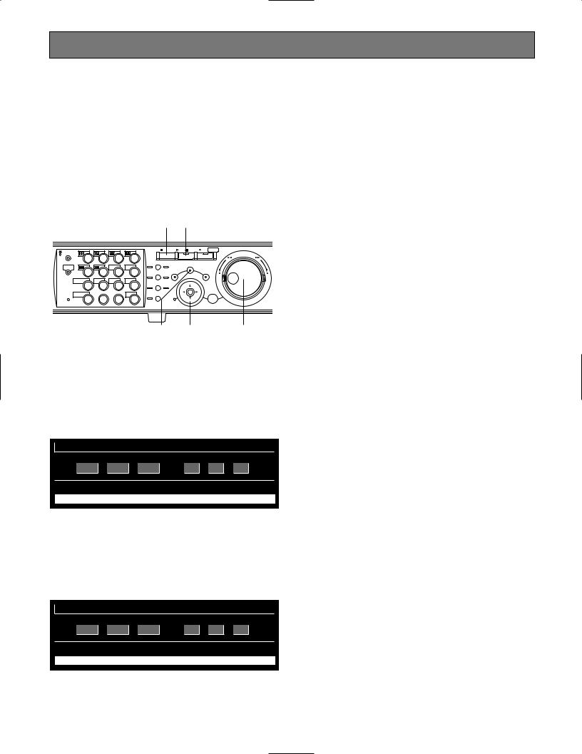
PLAYBACK FROM A DESIGNATED TIME AND DATE
Note: This feature is available only when "HDD NORMAL/ EVENT AREA" or "HDD COPY AREA" is selected with the DISK SELECT window. When "COPY 1" or "COPY 2" is selected, this feature is not available. Refer to page 25 for further information about the DISK SELECT window.
It is possible to play recorded images from a designated time and date without stopping recording.
Playback images will be displayed on monitor 2 and the VGA monitor.
v c
|
MONITOR1 |
|
|
|
|
STOP |
PLAY PAUSE REC - REC STOP |
|
R |
MONITOR2 |
|
|
|
|
|
REV |
FWD |
1 |
2 |
3 |
4 |
|
|
|
|
|
|
PAN/ |
GOTO |
|
|
||||
R |
|
|
|
|
SEARCH |
|
||
SHIFT |
|
SEQ |
OSD |
TILT |
LAST |
|
||
|
|
|
PAN/TILT |
SETUP |
|
|||
|
5 |
6 |
7 |
8 |
ZOOM/ |
A-B SLOW |
/ESC |
|
|
|
|
|
|
FOCUS |
REPEAT |
– |
+ |
|
DISK SELECT |
COPY |
TEXT |
MARK |
|
|
||
|
|
|
|
|
||||
|
9 |
10/0 |
11 |
12 |
IRIS |
LISTED |
|
|
|
EL-ZOOM |
|
LOGOUT |
LOGOUT |
PRESET |
|
|
|
|
|
/AUTO |
|
|
|
|||
2 |
13 |
14 |
15 |
16 |
|
SET |
|
|
|
BUSY |
|
||||||
|
|
|
|
|
|
|
|
z x x
zPress the SEARCH button repeatedly until the time and date designation window is displayed.
The time and date designation window will be displayed on monitor 2 and the VGA monitor.
START
JAN . 1 . 04 |
12 : 00 : 00 AM |
TIME&DATE  SEARCH
  REC EVENT
  SEARCH
  VMD
VMD  SEARCH
  MARK
MARK
xEnter the start time using the jog dial and the arrows button.
Select the time and date using the jog dial. To move the cursor, use the arrows button (A B).
START
FEB . 2 . 04 |
12 : 00 : 00 AM |
TIME&DATE  SEARCH
  REC EVENT
  SEARCH
  VMD
VMD  SEARCH
  MARK
MARK
cPress the PLAY/PAUSE button.
The indicator on the PLAY/PAUSE button will light and start playback from the entered time and date.
If there is no recorded image after the entered time:
When there are images recorded after the entered time, the oldest recorded image after the entered time will be played. When there are no images recorded after the entered time, the newest recorded image before the entered time will be played.
vPress the STOP button.
The indicator on the PLAY/PAUSE button will go off and stop playback.
Live images will be displayed on monitor 2 and the VGA monitor.
27

SEARCH AND PLAY
There are 3 ways to search for a recorded image and play it when "HDD NORMAL/EVENT AREA" or "HDD COPY AREA" is selected with the DISK SELECT window.
•Search for a recording event and play it (Recording event search) (see below)
•Search for a motion detected time and date from the recorded images and play it (VMD search) (page 36)
•Search for a marked point and play it (Marking search) (page 41)
When "COPY 1" or "COPY 2" is selected with the DISK SELECT window, the following is available.
• Search for copied recorded images and play it back (Copy Data Search) (page 32)
Note: Playback images will be displayed on a single screen on monitor 2 and the VGA monitor. To play in a multi-screen, switch to a multi-screen after starting playback.
■ Search for a Recording Event and Play it (Recording Event Search)
Note: This feature is available only when "HDD NORMAL/EVENT AREA" or "HDD COPY AREA" is selected with the DISK SELECT window. When "COPY 1" or "COPY 2" is selected, this feature is not available. Refer to page 25 for further information about the DISK SELECT window.
Display a list or a thumbnail of recording events, and select the desired recording event from them to play it. It is possible to search using the following filters:
Search Filters
TIME & DATE |
Search for only images recorded in the entered time range. |
|
CAMERA |
Search for only recorded images from the selected camera channel. |
|
REC EVENT |
Search for only images recorded in the selected recording mode. |
|
|
It is possible to search for images recorded in the following recording modes: |
|
|
EMERGENCY: Emergency recording (Refer to page 21.) |
|
|
VMD: |
Event recording performed when motion was detected. |
|
TERMINAL: |
Event recording performed when a terminal alarm was detected. |
|
COMMAND: |
Event recording performed when a command alarm was detected. |
|
VIDEO LOSS: |
Event recording performed when video loss occurred. |
|
MANUAL: |
Manual recording (Refer to page 20.) |
|
SCHEDULE: |
Schedule recording (Refer to page 119.) |
|
|
|
TEXT |
Search for only images recorded with text information. |
|
● Recording Event List Window
|
|
|
|
|
|
|
|
|
|
|
|
|
|
|
|
|
|
|
|
|
|
|
|
|
|
|
|
|
|
|
|
|
|
|
Search filter buttons |
|
|
|
|
|
|
|
|
|
|
|
|
|
|
|
|
|
|
|
|
|
|
|
|
|
|
|
|
|
|
|
|
|
|
|
Filter cancel button |
|
|
|
|
|
|
|
|
|
|
|
|
|
|
|
|
|
|
|
|
|
|
|
|
|
|
|
|
|
|
|
|
|
|
|
|
|
|
|
|
|
|
|
|
|
|
|
|
|
|
|
|
|
|
|
|
|
|
|
|
|
|
|
|
|
|
|
|
|
|
|
|
|
|
|
|
|
|
|
|
|
|
|
|
TIME&DATE |
CAMERA |
|
|
REC EVENT |
TEXT |
UNLOCK FILTER |
|
|
|
|
|
|
|
|
|
|
|||||||
Camera channel |
|
|
|
|
|
TIME&DATE |
|
|
CAM |
REC EVT |
|
TEXT |
|
|
|
|
|
|
|
|
|
Recording event |
|||||||||||||
|
|
|
|
|
|
|
|
|
|
|
|
|
|
|
|||||||||||||||||||||
|
|
|
|
|
|
|
|
|
|
|
|
AUG.20.04 3:04:23 PM |
|
|
01ch |
MANUAL |
ABCDEFGHIJ |
|
|
|
|
|
|
|
|
|
|
||||||||
|
|
|
|
|
|
|
|
|
|
|
|
AUG.20.04 3:01:24 PM |
|
|
01ch |
MANUAL |
ABCDEFGHIJ |
|
|
|
|
|
|
|
|
|
|
||||||||
|
|
|
|
|
|
|
|
|
|
|
|
AUG.20.04 3:00:40 PM |
|
|
01ch |
MANUAL |
ABCDEFGHIJ |
|
|
|
|
|
|
|
|
|
|
||||||||
Time and date |
|
|
|
|
|
|
|
|
|
AUG.20.04 3:00:00 PM |
|
|
01ch |
MANUAL |
ABCDEFGHIJ |
|
|
|
|
|
|
|
|
|
Text information |
||||||||||
|
|
|
|
|
|
|
|
|
AUG.20.04 2:59:11 PM |
|
|
01ch |
MANUAL |
ABCDEFGHIJ |
|
|
|
|
|
|
|
|
|
||||||||||||
|
|
|
|
|
|
|
|
|
|
|
|
|
|
|
|
|
|
|
|
|
|
|
|
||||||||||||
|
|
|
|
|
|
|
|
|
|
|
|
AUG.20.04 2:45:45 PM |
|
|
01ch |
MANUAL |
ABCDEFGHIJ |
|
|
|
|
|
|
|
|
|
|
||||||||
|
|
|
|
|
|
|
|
|
|
|
|
AUG.20.04 2:44:09 PM |
|
|
01ch |
MANUAL |
ABCDEFGHIJ |
|
|
|
|
|
|
|
|
|
|
||||||||
|
|
|
|
|
|
|
|
|
|
|
|
AUG.20.04 2:33:16 PM |
|
|
01ch |
MANUAL |
ABCDEFGHIJ |
|
|
|
|
|
|
|
|
|
|
||||||||
Time range of the listed data |
|
|
|
|
|
|
|
AUG.20.04 3:22:10 AM AUG.20.04 2:31:18 AM |
TOTAL |
100 |
|
|
|
|
|
|
|
|
|
|
Number of the listed data |
||||||||||||||
|
|
|
|
|
|
|
|
|
|
|
|
||||||||||||||||||||||||
|
|
|
|
|
|
|
|
|
|
|
|
TIME&DATE |
SEARCH |
REC EVENT |
SEARCH |
|
VMD SEARCH MARK |
|
|
|
|
|
|
|
|
|
|
|
Search information |
||||||
|
|
|
|
|
|
|
|
|
|
|
|
|
|
|
|
|
|
|
|
|
|
||||||||||||||
|
|
|
|
|
|
|
|
|
|
|
|
|
|
|
|
|
|
|
|
|
|
|
|
|
|
|
|
|
|
|
|
|
|
|
|
28
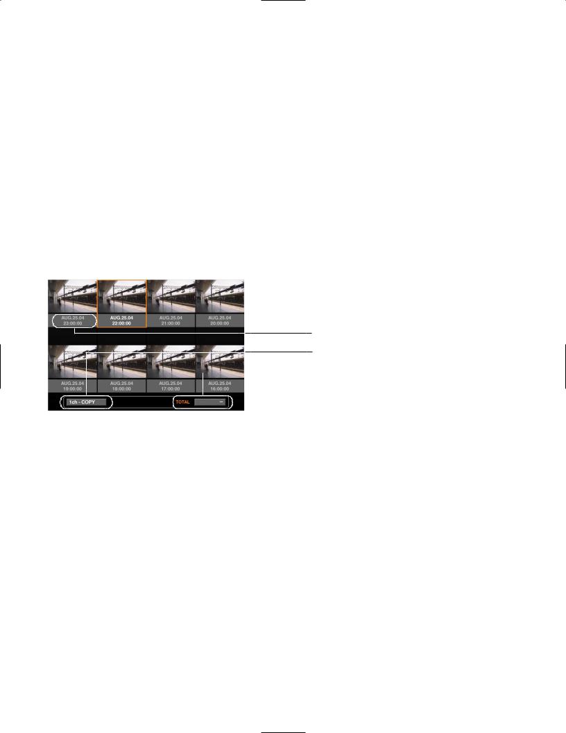
Search filter buttons: |
Selects the search filter |
Filter cancel button: |
Cancels the selected search filter and lists all recording events |
Time and date: |
<When searched by recording event> |
|
The time when recording started will be displayed. |
|
<When searched by VMD> |
|
The time when motion was detected will be displayed. |
|
<When searched by marked point> |
|
The time when the point was marked will be displayed. |
Camera channel: |
The camera channel of the recorded image will be displayed. The recorded image of |
|
the displayed camera channel will be played on a single screen. |
Recording event: |
The recording mode will be displayed. |
Text information: |
The first several characters of text information will be displayed if the image has text |
|
information. |
Time range of the listed data: |
The time range of the listed data will be displayed. |
Number of the listed data: |
The number of the listed data will be displayed. |
Search information: |
The search filter will be displayed. (A filter of the currently displayed list will be dis- |
|
played in orange.) |
● Recording Event Thumbnail Window
Time and date
Camera channel/Recording event


 Number of the listed data
Time and date: |
<When searched by recording event> |
|
The time when recording started will be displayed. |
|
<When searched by VMD> |
|
The time when motion was detected will be displayed. |
|
<When searched by marked point> |
|
The time when the point was marked will be displayed. |
Camera channel/Recording event: The camera channel of the recorded image will be displayed. The recorded image of the displayed camera channel will be played on a single screen. The recording mode also will be displayed.
Number of the listed data: The number of the listed data will be displayed.
Notes:
•Some images displayed in the thumbnail window may not match with their respective displayed recorded time due to playing of compressed recorded images.
•When the clock of the unit has been changed by editing the time and date settings or by the auto time adjustment function, overlapping of the time ranges of the images recorded before and after the time adjustment could occur. In this case, the thumbnail display may not function properly.
29
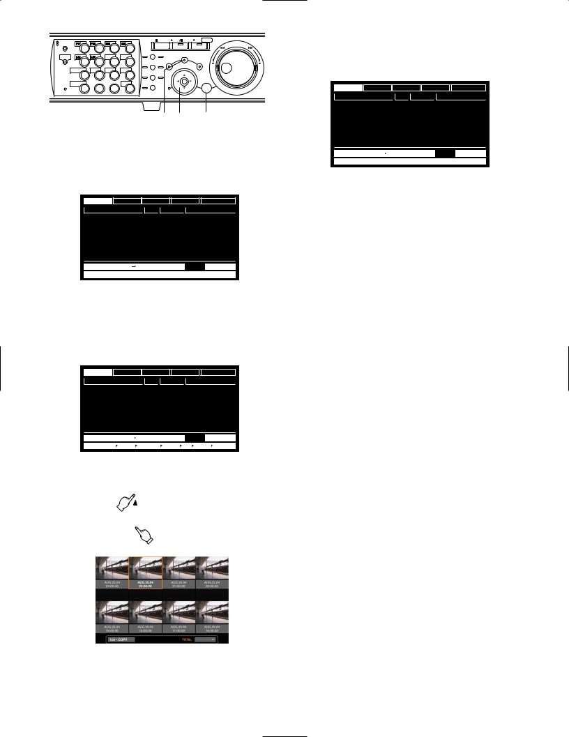
MONITOR1 |
|
|
|
|
STOP |
PLAY PAUSE REC - REC STOP |
|
MONITOR2 |
2 |
3 |
4 |
|
|
REV |
FWD |
1 |
PAN/ |
GOTO |
|
|
|||
|
|
|
|
SEARCH |
|
||
SHIFT |
|
SEQ |
OSD |
TILT |
LAST |
|
|
|
|
PAN/TILT |
SETUP |
|
|||
5 |
6 |
7 |
8 |
|
|
||
ZOOM/ |
A-B SLOW |
/ESC |
|
||||
|
|
|
|
FOCUS |
REPEAT |
– |
+ |
DISK SELECT |
COPY |
TEXT |
MARK |
|
|
||
|
|
|
|
||||
9 |
10/0 |
11 |
12 |
IRIS |
LISTED |
|
|
EL-ZOOM |
|
LOGOUT |
LOGOUT |
PRESET |
|
|
|
|
/AUTO |
|
|
|
|||
13 |
14 |
15 |
16 |
|
SET |
|
|
|
|
|
|||||
|
|
|
|
|
BUSY |
|
|
z z x x
zPress the SEARCH button repeatedly until the recording event list window is displayed.
TIME&DATE CAMERA |
REC EVENT |
TEXT |
UNLOCK FILTER |
||
TIME&DATE |
CAM |
REC EVT |
|
TEXT |
|
AUG.20.04 3:04:23 PM |
01ch |
MANUAL |
ABCDEFGHIJ |
||
AUG.20.04 3:01:24 PM |
01ch |
MANUAL |
ABCDEFGHIJ |
||
AUG.20.04 3:00:40 PM |
01ch |
MANUAL |
ABCDEFGHIJ |
||
AUG.20.04 3:00:00 PM |
01ch |
MANUAL |
ABCDEFGHIJ |
||
AUG.20.04 2:59:11 PM |
01ch |
MANUAL |
ABCDEFGHIJ |
||
AUG.20.04 2:45:45 PM |
01ch |
MANUAL |
ABCDEFGHIJ |
||
AUG.20.04 2:44:09 PM |
01ch |
MANUAL |
ABCDEFGHIJ |
||
AUG.20.04 2:33:16 PM |
01ch |
MANUAL |
ABCDEFGHIJ |
||
AUG.20.04 3:22:10 AM AUG.20.04 2:31:18 AM |
TOTAL |
100 |
|||
TIME&DATE  SEARCH
  REC EVENT
  SEARCH
  VMD
VMD  SEARCH
  MARK
MARK
The recording event list window will be displayed on monitor 2 and the VGA monitor.
Use the arrows button (C D) to switch between displaying the list window and the thumbnail window alternately.
To search using a search filter, go to step 4.
TIME&DATE CAMERA |
REC EVENT |
TEXT |
UNLOCK FILTER |
||
TIME&DATE |
CAM |
REC EVT |
|
TEXT |
|
AUG.20.04 3:04:23 PM |
01ch |
MANUAL |
ABCDEFGHIJ |
||
AUG.20.04 3:01:24 PM |
01ch |
MANUAL |
ABCDEFGHIJ |
||
AUG.20.04 3:00:40 PM |
01ch |
MANUAL |
ABCDEFGHIJ |
||
AUG.20.04 3:00:00 PM |
01ch |
MANUAL |
ABCDEFGHIJ |
||
AUG.20.04 2:59:11 PM |
01ch |
MANUAL |
ABCDEFGHIJ |
||
AUG.20.04 2:45:45 PM |
01ch |
MANUAL |
ABCDEFGHIJ |
||
AUG.20.04 2:44:09 PM |
01ch |
MANUAL |
ABCDEFGHIJ |
||
AUG.20.04 2:33:16 PM |
01ch |
MANUAL |
ABCDEFGHIJ |
||
AUG.20.04 3:22:10 AM |
AUG.20.04 2:31:18 AM |
TOTAL |
100 |
TIME&DATE SEARCH |
REC EVENT SEARCH |
VMD SEARCH |
MARK |
<List window>

xUse the arrows button (A B) to select a search filter (TIME & DATE, CAMERA, REC EVENT, TEXT), and press the SET button.
TIME&DATE CAMERA |
REC EVENT |
TEXT |
UNLOCK FILTER |
||
TIME&DATE |
CAM |
REC EVT |
|
TEXT |
|
AUG.20.04 3:04:23 PM |
01ch |
MANUAL |
ABCDEFGHIJ |
||
AUG.20.04 3:01:24 PM |
01ch |
MANUAL |
ABCDEFGHIJ |
||
AUG.20.04 3:00:40 PM |
01ch |
MANUAL |
ABCDEFGHIJ |
||
AUG.20.04 3:00:00 PM |
01ch |
MANUAL |
ABCDEFGHIJ |
||
AUG.20.04 2:59:11 PM |
01ch |
MANUAL |
ABCDEFGHIJ |
||
AUG.20.04 2:45:45 PM |
01ch |
MANUAL |
ABCDEFGHIJ |
||
AUG.20.04 2:44:09 PM |
01ch |
MANUAL |
ABCDEFGHIJ |
||
AUG.20.04 2:33:16 PM |
01ch |
MANUAL |
ABCDEFGHIJ |
||
AUG.20.04 3:22:10 AM AUG.20.04 2:31:18 AM |
TOTAL |
100 |
|||
TIME&DATE  SEARCH
  REC EVENT
  SEARCH
  VMD
VMD  SEARCH
  MARK
MARK
When a search filter is selected, the respective search filter window will be displayed.
Select "UNLOCK FILTER" and press the SET button to cancel the selected filter.
Refer to page 28 about search filters.
<Thumbnail window>
30
Loading...