

Panasonic SV-AV50S, SV-AV50 Operating Instructions Manual
Operating Instructions
SD Video Camera
Model No. SV-AV50
Before use, please read these instructions completely.
ENEB ENEG GC GK
VQT0J51

Before opening the CD-ROM package, please read the following.
End User License Agreement
You (“Licensee”) are granted a license for the Software defined in this End User License
Agreement (“Agreement”) on condition that you agree to the terms and conditions of this
Agreement. If Licensee does not agree to the terms and conditions of this Agreement, promptly
return the Software to Matsushita Electric Industrial Co., Ltd. (“Matsushita”), its distributors or
dealers from which you made the purchase.
Article 1 License
Licensee is granted the right to use the Software, including the information recorded or described
on the CD-ROM, instruction manuals, and any other media provided to Licensee (collectively
“Software”), but all applicable rights to patents, copyrights, trademarks and trade secrets in the
Software are not transferred to Licensee.
Article 2 Use by a Third Party
Licensee may not use, copy, modify, transfer or allow any third party, whether free of charge or
not, to use, copy or modify the Software, except as expressly provided for in this Agreement.
Article 3 Restrictions on Copying the Software
Licensee may make a single copy of the Software in whole or in part solely for back-up purpose.
Article 4 Computer
Licensee may use the Software only on one computer, and may not use it on more than one
computer.
Article 5 Reverse Engineering, Decompiling or Disassembly
Licensee may not reverse engineer, decompile, or disassemble the Software, except to the extent
either of them is permitted under law or regulation of the country where Licensee resides.
Matsushita, or its distributors will not be responsible for any defects in the Software or damage to
Licensee caused by Licensee’s reverse engineering, decompiling, or disassembly of the
Software.
Article 6 Indemnification
The Software is provided “AS-IS” without warranty of any kind, either expressed or implied,
including, but not limited to, warranties of non-infringement, merchantability and/or fitness for a
particular purpose. Further, Matsushita does not warrant that the operation of the Software will be
uninterrupted or error free. Matsushita or any of its distributors will not be liable for any damage
suffered by Licensee arising from or in connection with Licensee’s use of the Software.
Article 7 Export Control
Licensee agrees not to export or re-export to any country the Software in any form without the
appropriate export licenses under regulations of the country where Licensee resides, if necessary.
Article 8 Termination of License
The right granted to Licensee hereunder will be automatically terminated if Licensee contravenes
any of the terms and conditions of this Agreement. Upon termination hereof, Licensee must
destroy the Software and related documentation together with all the copies thereof at Licensee’s
own expense.
2

Contents
End User License Agreement ................... 2
Information for Your Safety ....................... 4
Caution for AC mains lead
(For UK only) ........................................... 5
Introduction ............................................... 6
Preparation
Standard Accessories ............................... 7
Optional Accessory ................................... 7
Controls and Components ........................ 8
Using the USB Cradle............................. 10
Power Supply .......................................... 10
Charging the Battery ................................11
Inserting a Memory Card......................... 12
Using the LCD Monitor............................ 13
Turning the Power On ............................. 15
Selecting Operation Modes..................... 16
Using the Menu Screen........................... 17
List of Menus........................................... 18
Setting Date and Time ............................ 20
Adjusting Brightness and
Colour Level on the LCD Monitor .......... 21
Basic Functions
Recording Still Pictures ........................... 22
Playing Back Still Pictures....................... 23
Recording Moving Pictures (MPEG4) ..... 24
Playing Back Moving Pictures
(MPEG4)................................................ 25
Voice Recording (Voice Recording
Function)................................................ 26
Listening to Voice Recordings
(Voice Playback) .................................... 27
Listening to Music (Audio Playback) ....... 28
Adjusting the Volume .............................. 29
Using the Remote Controller/
Earphones ............................................. 30
Advanced Functions
Digital Zoom Function ............................. 31
Night View Function ................................ 31
Backlight Compensation Function........... 32
Adjusting White Balance ......................... 33
Erasing the Files Recorded on
a Memory Card ...................................... 34
Protecting Files (File Protection) ............. 35
Writing Printing Data on a Memory Card
(DPOF Setting) ...................................... 36
Playing Back Still Pictures One by One
(P. Slide show) ....................................... 37
Formatting the Memory Card .................. 38
Playing Back on an external device ........ 39
On a Personal Computer
About the supplied software .................... 40
USB Driver .............................................. 42
SD-MovieStage ....................................... 42
SD-Jukebox............................................. 43
Installing USB Driver ............................... 44
Installing SD-MovieStage Ver.2.5............ 44
Installing SD-Jukebox Ver.4 .................... 45
Connecting to the PC .............................. 46
Starting the Software ............................... 46
Disconnecting the USB Cable Safely...... 47
If you no longer need software
(Uninstall)............................................... 47
Constructing a Folder when
the Memory Card is used with a PC ...... 48
Others
Charge the Built-in Battery for
Maintaining the Date Information ........... 49
After Use ................................................. 49
Indications ............................................... 50
Cautions for Use ..................................... 52
Notes and Hints....................................... 55
Before Requesting Service ..................... 64
Specifications .......................................... 67
Index .........................................Back Cover
3
Dear Customer,
We would like to take this opportunity to
thank you for purchasing this Panasonic SD
Video Camera. Please read these
Operating Instructions carefully and keep
them handy for future reference.
Information for Your
Safety
WARNING
TO REDUCE THE RISK OF FIRE OR
SHOCK HAZARD AND ANNOYING
INTERFERENCE, USE ONLY THE
RECOMMENDED ACCESSORIES AND
DO NOT EXPOSE THIS EQUIPMENT TO
RAIN OR MOISTURE. DO NOT REMOVE
THE COVER (OR BACK); THERE ARE
NOT USER SERVICEABLE PARTS
INSIDE. REFER SERVICING TO
QUALIFIED SERVICE PERSONNEL.
IMPORTANT
Please respect all copyrights.
Whatever you have recorded and
created can be used for your personal
entertainment only. Under copyright
laws, other materials cannot be used
without obtaining permission from the
holders of the copyrights.
≥Injury or material damage resulting
from any kind of use that is not in
accordance with the operating
Instructions are the sole responsibility
of the user.
≥If the SD Video Camera is used
continuously for a long time or used at a
high ambient temperature, red, blue,
green or white dots may appear on the
screen and be recorded on a still picture.
This is due to the rise of the temperature
inside the body. This is not a malfunction.
Under this condition, turn the SD Video
Camera off and leave it for a while.
≥The manufacturer shall in no event be
liable for the loss of recordings due to
malfunction or defect of this SD Video
Camera, its accessories or Memory Card.
4
≥Please note that the actual controls and
components, menu items, etc. of your SD
Video Camera may look somewhat
different from those shown in the
illustrations in these Operating
Instructions.
≥SD logo is a trademark.
≥In this Operating Instructions,
“Memory Card” and “Card” mean
“SD Memory Card”.
≥The SD Video Camera uses copyright-
protected technologies and is protected by
the patented technologies and intellectual
properties of Japan and the U.S. To use
these copyright-protected technologies,
authorization of the Macrovision Company
is required. It is prohibited to disassemble
or modify the SD Video Camera.
≥(l 00) indicates the page to be referred
to.
≥Note that the SD Video Camera may not
play back the data recorded or created on
another product and another product may
not play back the data recorded on the SD
Video Camera.
≥The nameplate of the SD Video Camera is
fixed on the bottom of the battery
compartment.
≥MPEG Layer-3 audio decoding technology
licensed from Fraunhofer IIS and
Thomson multimedia.
THE SOCKET OUTLET SHALL BE
INSTALLED NEAR THE EQUIPMENT
AND SHALL BE EASILY ACCESSIBLE.
CAUTION
Danger of explosion if battery is
incorrectly replaced.
Replace only with the same or
equivalent type recommended by the
manufacturer.
Dispose of used batteries according to
the manufacturer’s instructions.
Caution for AC mains lead (For UK only)
Message to User who has Power Cable as an accessory. (l 7)
For your safety, please read the following text carefully.
This appliance is supplied with a moulded
three-pin mains plug for your safety and
convenience. A 5-ampere fuse is fitted in
this plug.
Should the fuse need to be replaced,
please ensure that the replacement fuse
has a rating of 5-amperes and it is
approved by ASTA or BSI to BS1362.
Check for the ASTA mark Ï or the BSI
mark Ì on the body of the fuse.
If the plug contains a removable fuse
cover you must ensure that it is refitted
when the fuse is replaced. If you lose the
fuse cover, the plug must not be used until
a replacement cover is obtained. A
replacement fuse cover can be purchased
from your local Panasonic Dealer.
IF THE FITTED MOULDED PLUG IS
UNSUITABLE FOR THE SOCKET
OUTLET IN YOUR HOME THEN THE
FUSE SHOULD BE REMOVED AND THE
PLUG CUT OFF AND DISPOSED OF
SAFELY.
THERE IS A DANGER OF SEVERE
ELECTRICAL SHOCK IF THE CUT OFF
PLUG IS INSERTED INTO ANY 13AMPERE SOCKET.
If a new plug is to be fitted, please
observe the wiring code as shown below.
If in any doubt, please consult a qualified
electrician.
As the colours of the wires in the mains
lead of this appliance may not correspond
with the coloured markings identifying the
terminals in your plug, proceed as follows:
The wire which is coloured BLUE must be
connected to the terminal in the plug
which is marked with the letter N or
coloured BLACK.
The wire which is coloured BROWN must
be connected to the terminal in the plug
which is marked with the letter L or
coloured RED.
Under no circumstances should either of
these wires be connected to the earth
terminal of the three-pin plug, marked with
the letter E or the Earth Symbol Ó.
Before Use
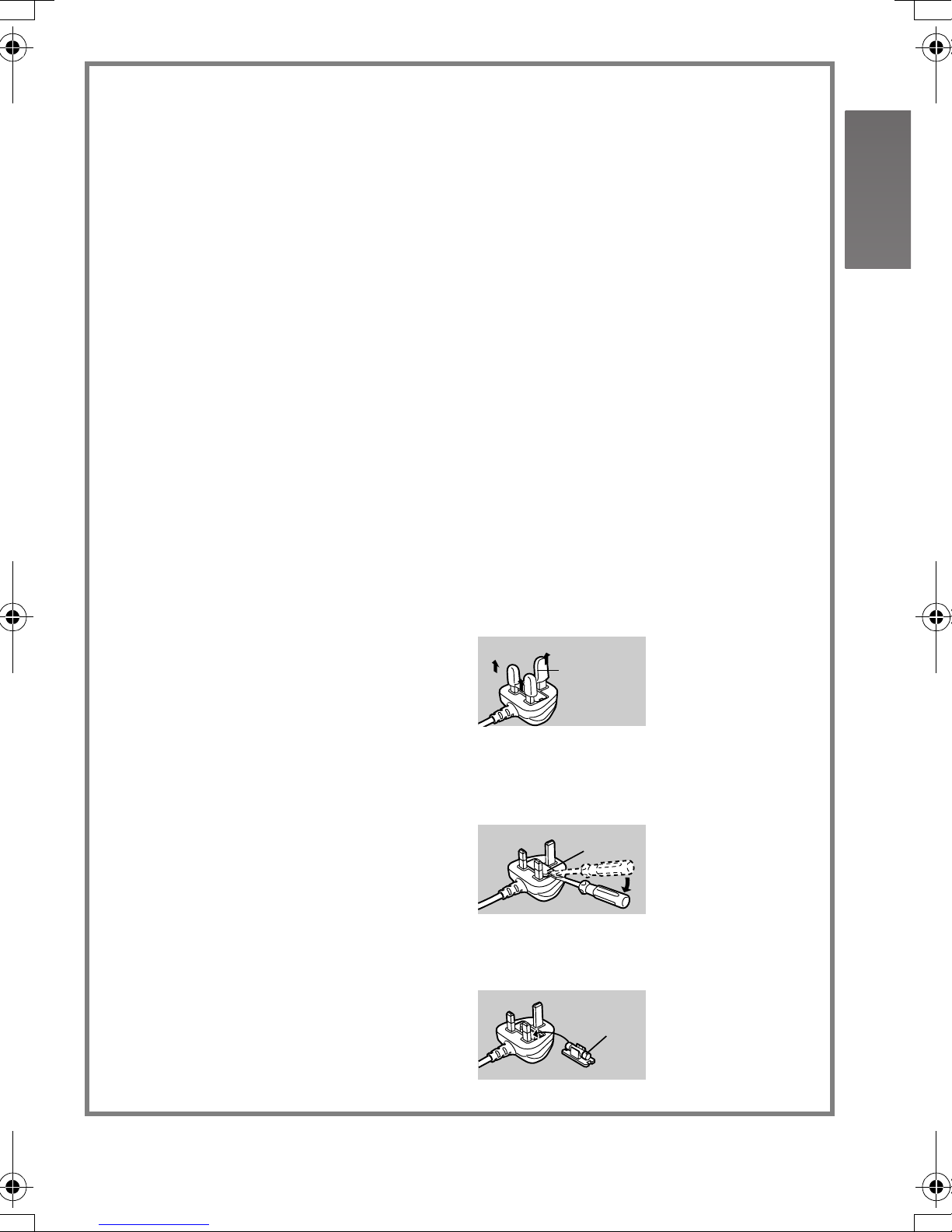
ª
Remove the Connector Cover as follows.
Connector
Cover
How to replace the Fuse
ª
1 Remove the Fuse Cover with a
screwdriver.
Fuse
Cover
IMPORTANT
ª
The wires in this mains lead are coloured
in accordance with the following code:
Blue: Neutral
Brown: Live
2 Replace the fuse and attach the Fuse
Cover.
Fuse
5
Introduction
This SD Video Camera can record MPEG4
moving pictures, still picture and voice data.
Additionally, it can play back a high quality
music file of the MPEG2-AAC and MP3
format (Records files with the supplied
SD-Jukebox Ver.4). And using the viewer
software, SD-MovieStage Ver.2.5 (supplied
accessory), the MPEG4 moving picture data
can be edited on the personal computer.
ªClock setting
When you purchase the SD Video
Camera, the clock setting has not been
performed. To start, please set the year,
month, date and time. (l 20)
Preparation
ªSales and Support
Information
Customer Care Centre
≥For UK customers: 08705 357357
≥For Republic of Ireland customers: 01 289
8333
≥Visit our website for product information
≥E-mail: customer.care@panasonic.co.uk
Technical Support for AV Software
≥For callers in UK: 08701 505610
≥For callers in ROI: 0044 8701 505610
Direct Sales at Panasonic UK
PRESS MENU TO SET CLOCK
≥Order accessory and consumable items
for your product with ease and confidence
by phoning our Customer Care Centre
Monday - Friday 9:00am – 5:30pm.
(Excluding public holidays).
≥Or go on line through our Internet
Accessory ordering application at
www.panasonic.co.uk
≥Most major credit and debit cards
accepted.
≥All enquiries transactions and distribution
facilities are provided directly by
Panasonic UK Ltd.
≥It couldn’t be simpler!
≥Also available through our Internet is
direct shopping for a wide range of
finished products, take a browse on our
website for further details.
.
6
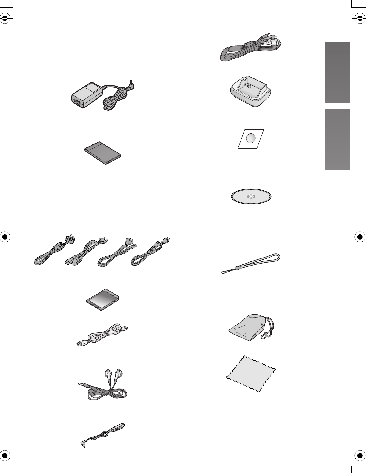
Standard Accessories
1 AC Adaptor
SV-AV50EB/EG (VSK0648)
SV-AV50GC/GK (VSK0649) (l 10)
≥Supplies power to the SD Video
Camera.
8 AV Cable (K2KC4CB00016) (l 39)
9 USB Cradle (VSK0663) (l 10)
2 Battery Pack (l 11)
≥Supplies power to the SD Video
Camera.
3 AC Mains Lead
A:SV-AV50EB (For UK) only
(K2CT3DA00003)
B:SV-AV50EG/GC (K2CR2DA00004)
C:SV-AV50GC only (K2CJ2DA00011)
D:SV-AV50GK only (K2CA2CA00020)
(l 10)
A
B
C
D
4 SD Memory Card (8 MB)
(RP-SD008BVE0) (l 12)
5 USB Cable (K1HA09BD0001) (l 46)
10 Lens Protection Sticker (VGQ8054)
(l 14)
11 CD-ROM (l 40)
USB Driver, SD-MovieStage Ver.2.5,
SD-Jukebox Ver.4,
Adobe Acrobat Reader
≥For using the SD-MovieStage Ver.2.5
and SD-Jukebox Ver.4, refer to the
PDF manual. This manual describes
installation only.
12 Hand Strap (VFC4029)
13 Carrying Case (VFC4030)
≥Put the SD Video Camera in the
supplied Carrying Case after use or
when carrying it.
6 Stereo earphones (LOBAB0000173)
(l 30)
7 Remote Controller (N2QCAD000005)
(l 30)
14 Cleaning Cloth (VFC3778)
Optional Accessory
1 Battery Pack (CGA-S003E/1B) (l 11)
≥Supplies power to the SD Video
Camera.
7
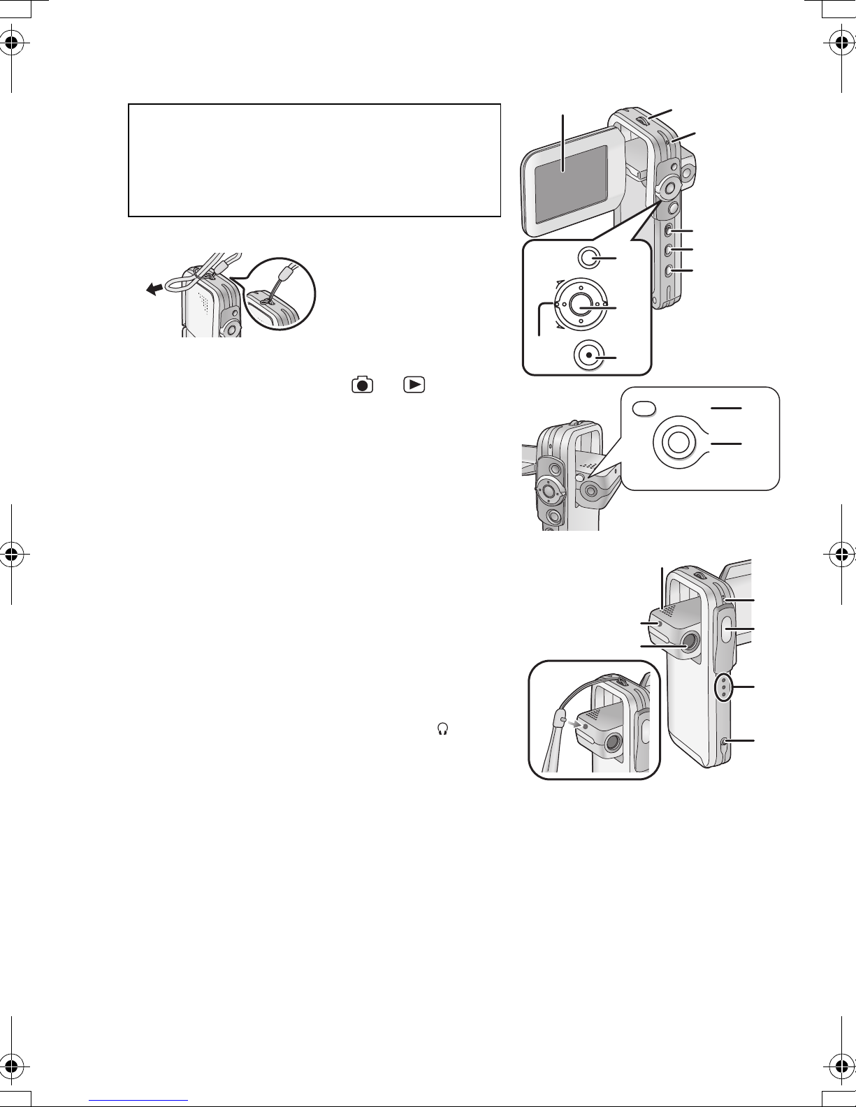
Controls and Components
1 LCD Monitor (l 13)
Due to limitations in LCD production technology,
there may be some tiny bright or dark spots on
the LCD Monitor screen. However, this is not a
malfunction and does not affect the recorded
picture.
2 Hand Strap Holder
3 Power/Card Access Lamp (l 11, 56)
4 Record/Play mode Switch [ ]/[ ] (l 16)
5 Mode Button [MODE] (l 16)
6 Power Button [Í] (l 15)
7 Zoom/Volume Lever [T/W] (l 29, 31)
8 Menu Button [MENU] (l 17)
9 Jog Ball
10 Recording Start/Stop Button (l 22, 24, 26)
11 Release Button [RELEASE] (l 13)
12 Night View Button [NIGHT VIEW] (l 31)
13 Speaker
14 Hand Strap fixation hole
15 Lens (l 54)
16 Microphone (built-in, monaural) (l 26)
17 Flash (l 22)
18 Grip (l 13)
7
14
1
MENU
Ô
×
8
9
10
ОЙЗИФЦЙЕЧ
13
14
15
2
3
4
5
6
ТЕМЕБУЕ
11
12
16
17
18
19 Remote Controller/Earphone Socket [
(l 30)
8
]
19
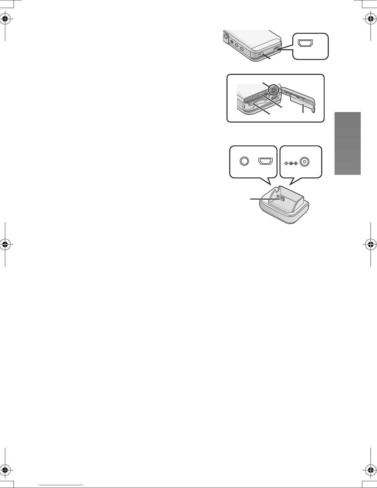
20 Card/Battery Door (l 11, 12)
≥Be sure to turn the power off while the Card/
Battery Door is open.
21 USB Cradle Connector [MULTI] (l 10)
22 Battery Lock (l 11)
23 Memory Card Slot (l 12)
24 Battery Slot (l 11)
25 AV Output Socket [A/V OUT] (l 39)
26 USB Port [USB] (l 46)
27 DC Input Socket [DC IN 4.8V] (l 10)
28 Device Connector (l 10)
22
20
23
24
MULTI
20
21
A/V OUT
USB
DC IN 4.8V
25 26 27
28
9
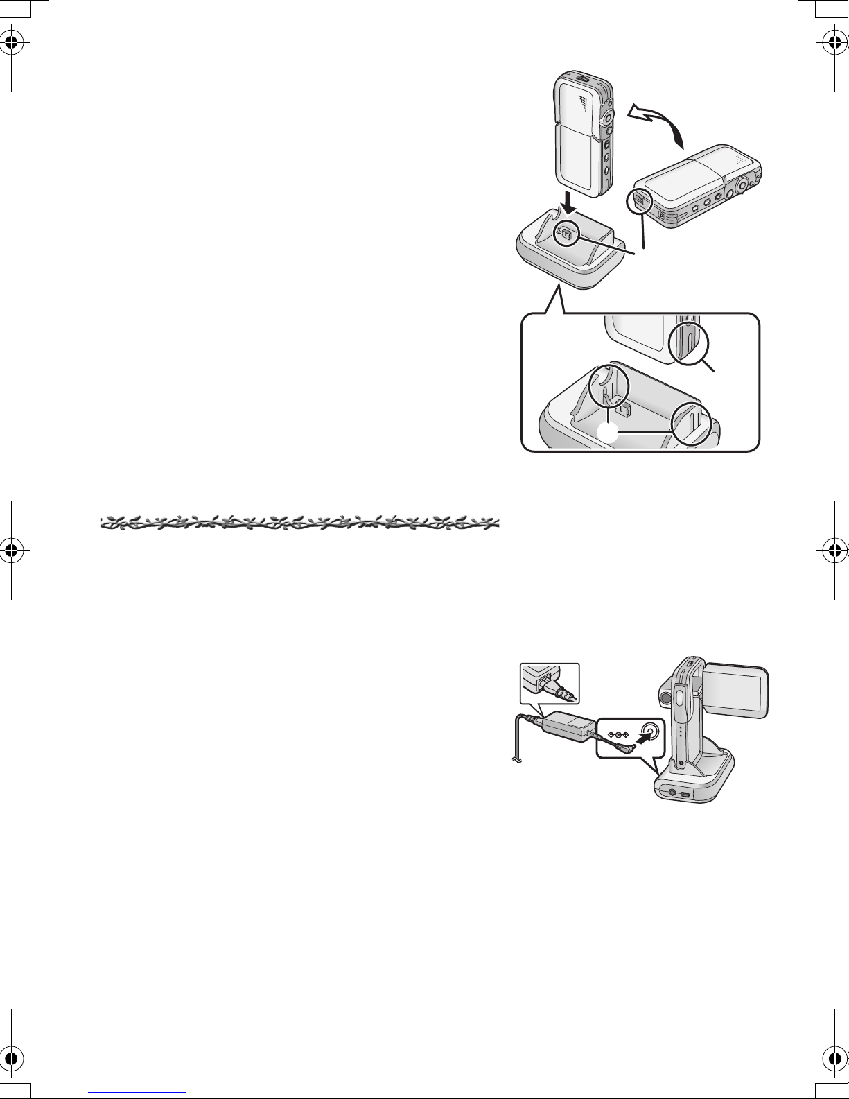
Using the USB Cradle
Inserting the camera into the USB cradle allows the
battery to be charged. The USB cradle also allows the
camera to be connected to external devices such as
your TV for viewing images. (l 39)
1 Place the SD Video Camera on the USB
Cradle.
≥The grooves A of the SD Video Camera fit in the
leading protrusions B.
≥Place the SD Video Camera on the USB Cradle
so that the mating connectors 1 are in
alignment.
1
1
≥Before fitting the SD Video Camera on the USB
Cradle, turn the SD Video Camera off.
Power Supply
ª
Using AC Adaptor
1 Place the SD Video Camera on the USB
Cradle.
2 Connect the DC Input Lead to the
[DC IN 4.8V] socket on the USB Cradle.
3 Connect the AC Mains Lead to the AC
Adaptor and the AC Mains socket.
≥The AC Mains Lead does not fit entirely into the
AC Adaptor socket. A gap will remain as shown
1.
A
B
3
1
2
DC IN 4.8V
10
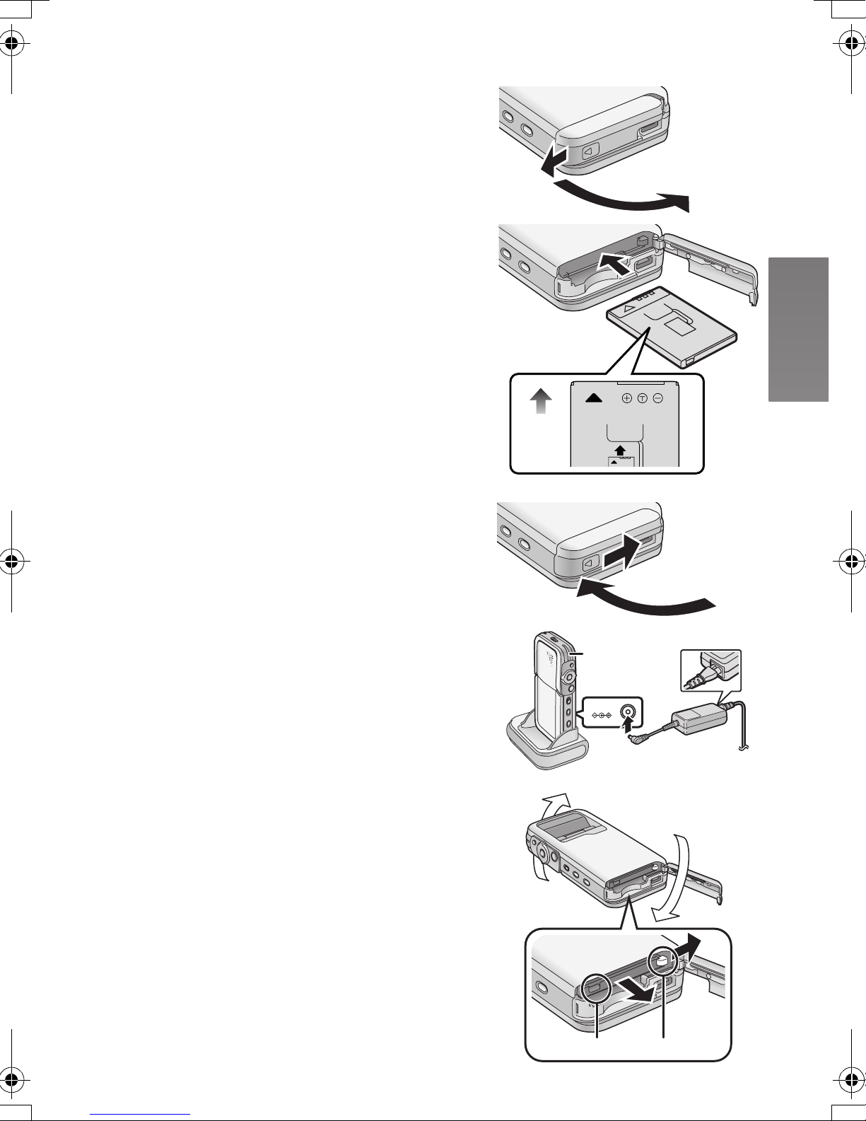
Charging the Battery
Be sure to turn the power switch on the camera off
when charging the battery.
1 Slide and open the Card/Battery Door.
2 Insert the battery all the way.
≥Confirm the direction of the battery.
≥Be sure to insert the battery until fixed with the
Battery Lock.
3 Close and lock the Card/Battery Door
while sliding it.
4 Place the SD Video Camera on the USB
Cradle.
5 Connect the DC Input Lead to the [DC IN
4.8V] socket on the USB Cradle.
6 Connect the AC Mains Lead to the AC
Adaptor and the AC Main socket.
≥Power/Card Access Lamp 1 flashes, and
Charging starts.
1
2
3
7 Wait until Power/Card Access Lamp 1
goes off.
≥When recharging is completed, Power/Card
Access Lamp goes off.
≥Under normal operation the charging light stays on
during charging. If it blinks a charging problem may
be occurring. Please see page 54 for more details.
ª Removing the Battery
1 Slide and open the Card/Battery Door.
2 Release the Battery Lock A and incline
this unit to remove the Battery.
≥When you cannot remove the battery, pull out the
projection part B to remove it.
3 Close and lock the Card/Battery Door
while sliding it.
1
5
DC IN 4.8V
6
2
AB
11
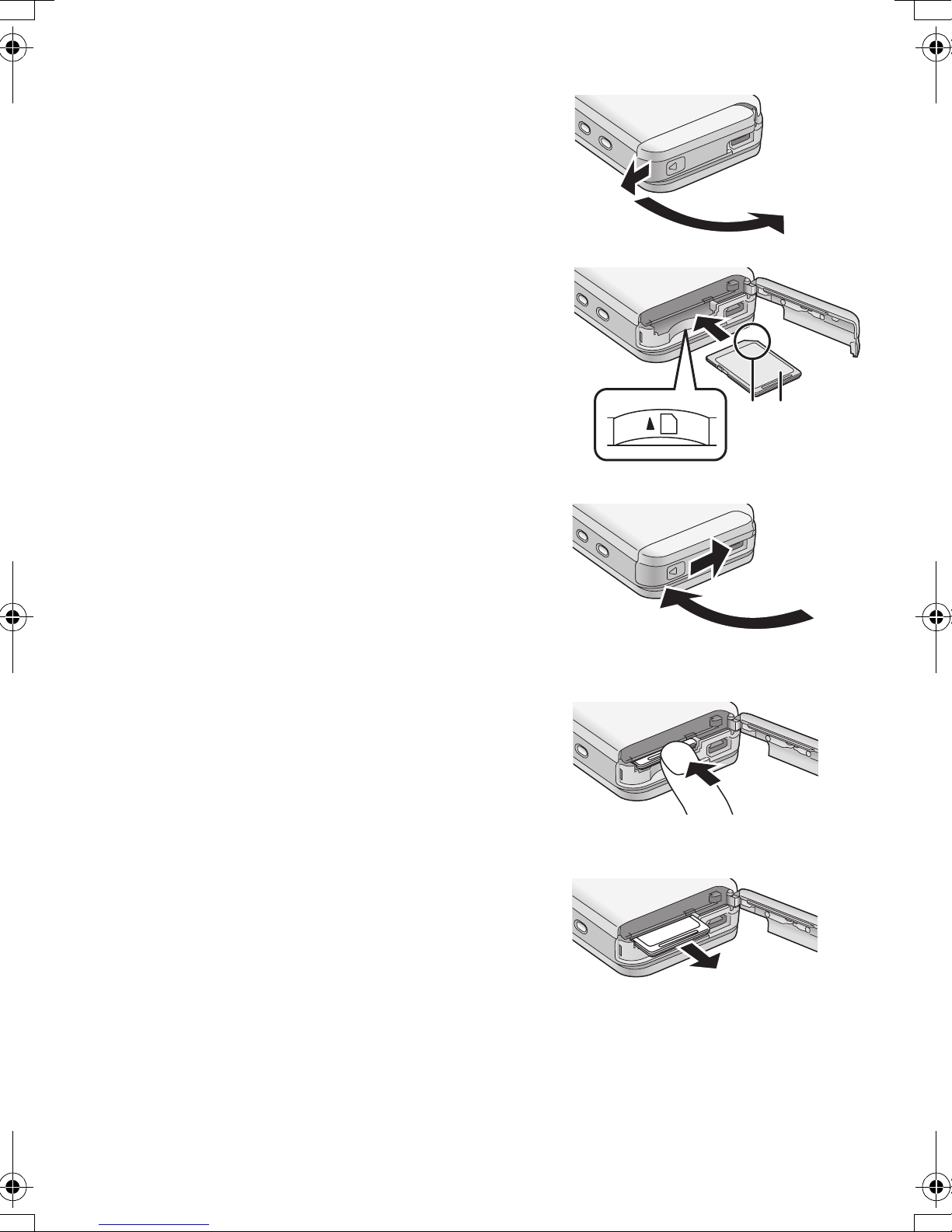
Inserting a Memory Card
Be sure to turn the power off when inserting the card.
1 Slide and open the Card/Battery Door.
2 Hold the Memory Card placing the cut off
1
corner
facing up, and then insert it all the way
until it clicks.
≥Turn off the SD Video Camera before inserting/
removing a Card.
≥Confirm the direction of the card.
1 at the front with the label 2
3 Close and lock the Card/Battery Door
while sliding it.
2
12
3
ªRemoving the Memory Card
1 Slide and open the Card/Battery Door.
2 Press the Card until it clicks to release.
3 Pull out the Card.
4 Close and lock the Card/Battery Door
while sliding it.
≥Keep the SD Memory Card out of the reach of
children to prevent swallowing.
2
3
12
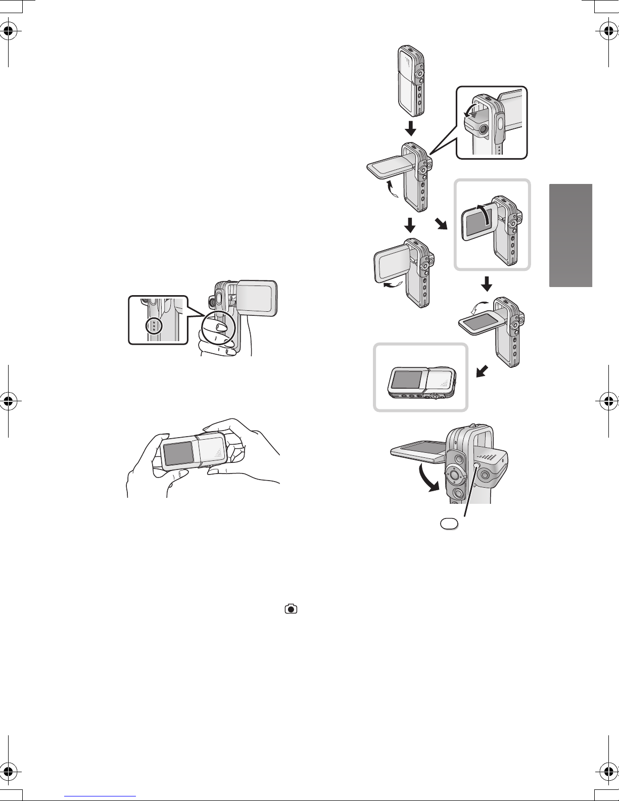
Using the LCD Monitor
During live recording the image can be viewed on the
LCD monitor. The monitor also allows you to review
previously recorded material.
1 Open the LCD Monitor.
≥The lens appears in an opposite side of the LCD
Monitor.
2 Adjust the LCD Monitor angle according
1,2
to the desired recording/playing angle.
1 : Use mainly when recording.
≥Position your finger on Grip A. When you
put your finger on the upper position of the
Grip, there are times when your finger may
touch the lens.
A
2 : Use mainly when playing back.
≥In this case, lean the LCD Monitor while
pressing the [RELEASE] Button.
1
2
2
1
3
The LCD Monitor can rotate up to the angles illustrated.
≥
1 : Up to 90° maximum
2 : Up to 90
3 : Up to 180
≥If the position of the LCD Monitor is set to 2, when
you set the Record/Play mode switch to [ ] mode
only the indication which is limited appears on screen
display.
≥Close the LCD Monitor while pressing the
[RELEASE] Button. (Take care not to get your finger
caught between the LCD Monitor and the body of the
SD Video Camera.)
° maximum
° maximum
ТЕМЕБУЕ
13
ªAttaching the Lens Protection Sticker
1 Attach the Lens Protection Sticker 1 to
the front of this unit. (Attach the Lens
Protection Sticker to the position of the
line 2.)
≥Put the finger under the Lens Protection Sticker
1.
1
1
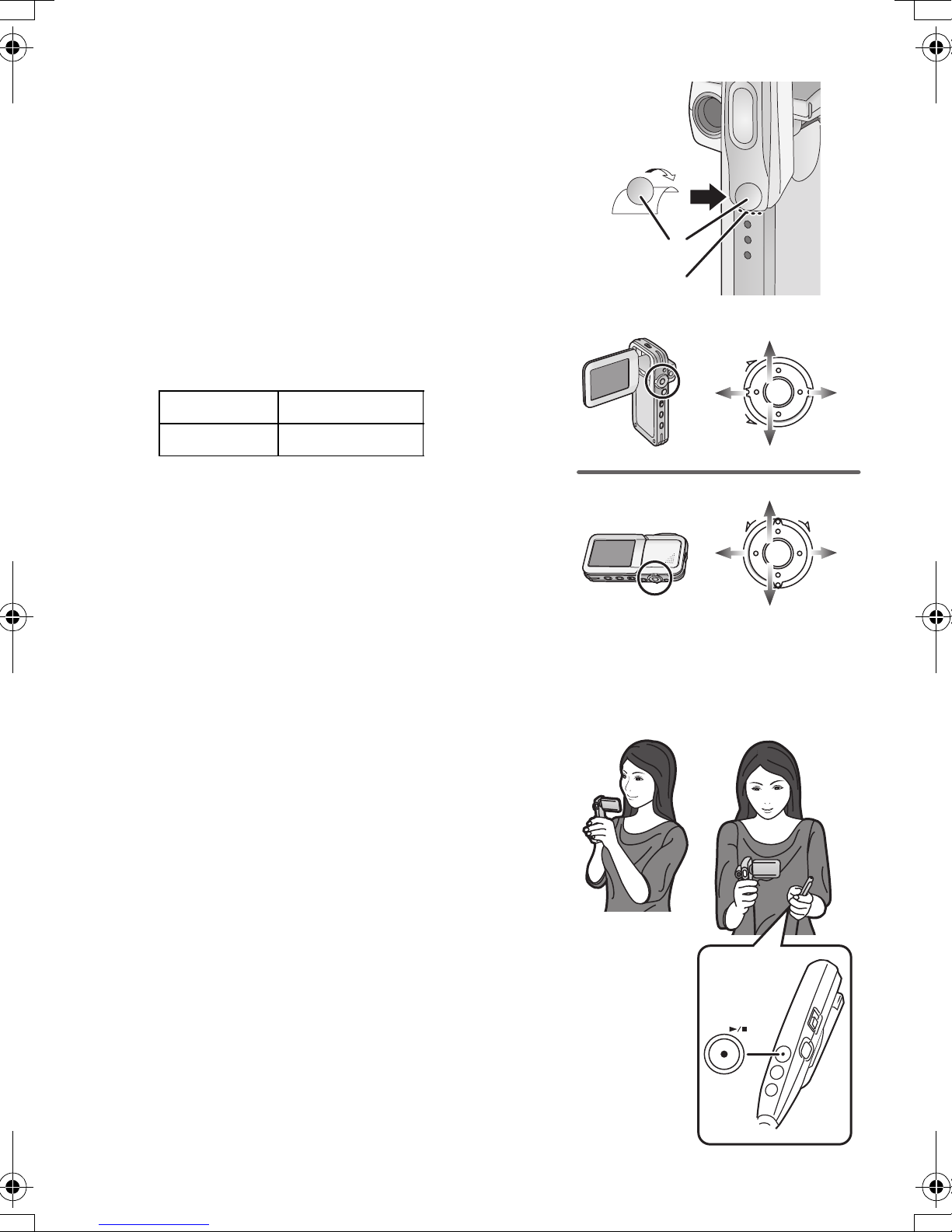
ªUsing the Jog Ball
As the angle of the LCD monitor is changed, so too
will the direction of movement using the Jog Ball.
A : Recording angle
B : Playing back angle
A : UP B : RIGHT
D : LEFT C : DOWN
≥When you keep pressing the [MENU] Button for
2 seconds or more in playback mode, the Jog Ball
and the Zoom/Volume Lever cannot be activated to
prevent wrong operations. The MENU screen also
does not appear. (The [¥ HOLD] indication appears.)
(The Jog Ball and the Zoom/Volume Lever are
activated when you keep pressing the [MENU]
Button for 2 seconds or more.)
ªRecording Still Pictures skillfully
The SD Video Camera automatically adjusts the
shutter speed of the camera to the subject’s
brightness.
A
B
2
D
D
A
Ô
B
×
C
A
×
Ô
B
C
When recording pictures in dark places*, the
shutter speed becomes slower. Be careful not to
shake the camera.
* e.g., Indoor, Shade.
≥When recording still pictures, hold the SD Video
Camera firmly with both hands, and take a stance.
≥When recording still pictures using the Remote
Controller (supplied), camera shake will be reduced.
≥Press the Recording Start/Stop Button ([1/∫]/[¥]) 1
on the Remote Controller.
≥When recording pictures of subjects in quick motion,
the picture or image may be blurred.
14
1

Turning the Power On
Select a desired mode from the mode selection screen
on the LCD Monitor.
1 Press the [Í] Button for 1 second or
more.
≥The SD Video Camera is turned on and the
Power/Card Access Lamp A is lit in red.
ª Auto power on mode
If you set the [Auto power on] to [On] in [Setup] on
[MENU], the SD Video Camera is automatically turned
on when LCD Monitor is opened.
≥When the battery is removed, the setting on the [Auto
power on] is turned to [Off]. (The setting on the [Auto
power on] may be turned to [Off] when the battery
power is drained. Please recharge the battery for this
feature to function.)
ª Turning the power off
1 Press the [Í] Button for 2 seconds or
1
A
more.
≥The SD Video Camera is turned off and the
Power/Card Access Lamp A is goes off.
≥When the LCD monitor is closed, the picture on
the LCD monitor disappears. However, the SD
Video Camera is not turned off.
≥When you do not operate the SD Video Camera for
about 5 or more minutes, the SD Video Camera is
automatically turned off. (Using the AC Adaptor,
when both the card and the battery are not inserted,
the SD Video Camera is not turned off automatically.)
15
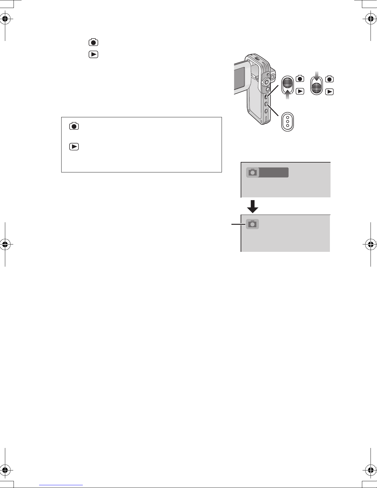
Selecting Operation Modes
MODE
1 Set to [ ] 1 to select Record Mode.
Set to [ ] 2 to select Play Mode.
2 Press the [MODE] Button to select a
Operation Mode.
≥Every time the [MODE] Button is pressed, the
Operation Mode changes as follows.
After several seconds, only icons are displayed. 3
≥
[ ]: Record mode
[PICTURE]l[MPEG4]l[VOICE]l[PICTURE]
[ ]: Play mode
[PICTURE]l[MPEG4]l[VOICE]l[AUDIO]l
[PICTURE]
ªAbout the Operation Modes
Seven operation modes are provided as follows.
≥Still picture (JPEG format still picture) record mode
(l 22)
≥Still picture (JPEG format still picture) play mode
(l 23)
≥Moving picture (MPEG4 format) record mode (l 24)
≥Moving picture (MPEG4 format) play mode (l 25)
≥Voice (VOICE format) record mode (l 26)
≥Voice (VOICE format) play mode (l 27)
≥Audio (MPEG2-AAC/MP3 format) play mode (l 28)
3
1
MODE
PICTURE
1
2
2
16
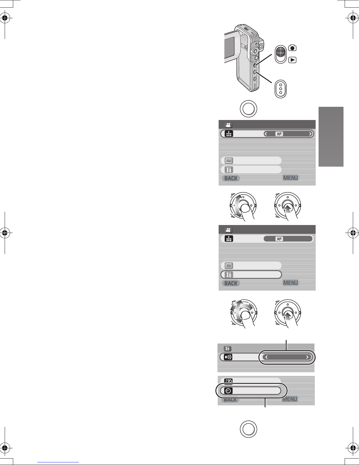
Using the Menu Screen
MODE
MENU
#WVQTGEQTFKPIUGVWR
':+6
4'%/'07
'ZVTCHKPG
&KURNC[UGVWR
/2')OQFG
5GVWR
#WVQTGEQTFKPIUGVWR
':+6
4'%/'07
'ZVTCHKPG
&KURNC[UGVWR
/2')OQFG
5GVWR
MENU
%COGTC
+PRWVUGNGEV
5'672
1HH
$GGR
':+6
ǻȃȈǢȃȗ
Џ
ǫȡȩ
(QTOCVECTF
λщᚨܭ
%NQEMUGV
ų
Allows the functions usable in the selected mode to be
set from the menu.
1 Select a desired mode. (l 16)
1
2 Press the [MENU] Button.
≥The menu in the selected mode is displayed.
3 Roll the Jog Ball UP or DOWN to select a
desired item.
4 Press the Jog Ball.
5 For selecting an item, roll the Jog Ball UP
or DOWN to select a desired item and
then LEFT or RIGHT to set the item. 1
For conducting an item, roll the Jog Ball
UP or DOWN to select a desired item and
then press the Jog Ball. 2
6 Press the [MENU] Button.
≥Menu screen disappears, and the selected item
is now being set.
≥Press the [MENU] Button when playing back the
moving picture, still picture or sound so you can edit
the file being played back.
≥When you keep pressing the [MENU] Button for
2 seconds or more in playback mode, the Jog Ball
and the Zoom/Volume Lever cannot be activated to
prevent wrong operations. The MENU screen also
does not appear. (The [¥ HOLD] indication appears.)
(The Jog Ball and the Zoom/Volume Lever are
activated when you keep pressing the [MENU]
Button for 2 seconds or more.)
2
3,4
5
MENU
4'%/'07
/2')OQFG
#WVQTGEQTFKPIUGVWR
ų
&KURNC[UGVWR
5GVWR
Ô
×
4'%/'07
/2')OQFG
#WVQTGEQTFKPIUGVWR
ų
&KURNC[UGVWR
5GVWR
Ô
MODE
'ZVTCHKPG
':+6
Ô
×
'ZVTCHKPG
':+6
Ô
6
×
5'672
$GGR
+PRWVUGNGEV
(QTOCVECTF
%NQEMUGV
MENU
×
1
1HH
%COGTC
':+6
2
17
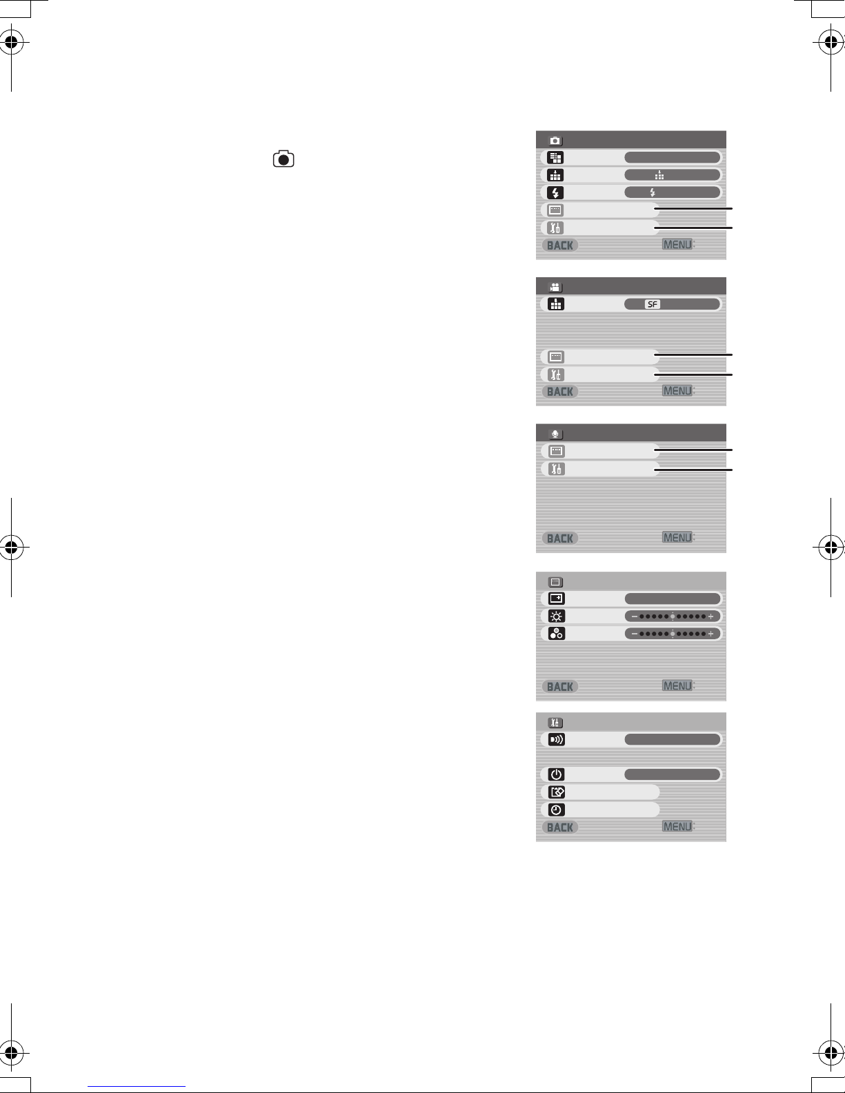
List of Menus
#WVQTGEQTFKPIUGVWR
+PRWVUGNGEV
%COGTC
':+6
4'%/'07
&KURNC[UGVWR
5GVWR
5WRGTHKPG
/2')OQFG
':+6
&+52.#;5'672
1P
+EQPFKURNC[
$TKIJVPGUU
%QNQWT
':+6
4'%/'07
&KURNC[UGVWR
5GVWR
':+6
4'%/'07
(KPG
&KURNC[UGVWR
2KEVWTGUK\G
3WCNKV[
5GVWR
(NCUJ
(NCUJQP
':+6
5'672
1P
(QTOCVECTF
$GGR
%NQEMUGV
#WVQRQYGTQP
1HH
The menu screens used differ slightly from the actual
menus. These are offered for simplified illustration
purposes.
ªRecord Mode [ ]
1 Still Picture Record Menu
Picture size [Picture size] (l 22)
Picture quality [Quality] (l 22)
Flash setting [Flash] (l 22)
Display setup [Display setup] 1
Initial setup [Setup] 2
Return to the previous screen [BACK]
2 MPEG4 Moving Picture Record Menu
Moving picture quality [MPEG4 mode] (l 24)
Display setup [Display setup] 1
Initial setup [Setup] 2
Return to the previous screen [BACK]
3 Voice Record Menu
Display setup [Display setup] 1
Initial setup [Setup] 2
Return to the previous screen [BACK]
1
2
3
4'%/'07
2KEVWTGUK\G
3WCNKV[
(NCUJ
&KURNC[UGVWR
5GVWR
4'%/'07
/2')OQFG
#WVQTGEQTFKPIUGVWR
ų
&KURNC[UGVWR
5GVWR
4'%/'07
&KURNC[UGVWR
5GVWR
ų
(NCUJQP
5WRGTHKPG
g
(KPG
1
2
':+6
1
2
':+6
1
2
Sub-Menu for Record Mode
1 Display setup [Display setup]
Display [Icon display]
≥When it is set to [On], superimposed indications
such as playback status and picture quality will be
displayed.
Brightness [Brightness] (l 21)
Colour level [Colour] (l 21)
Return to the previous screen [BACK]
2 Initial setup [Setup]
Beep sound setting [Beep]
≥When it is set to [On], beeps for confirmation or
alarm.
Auto power on [Auto power on] (l 15)
Card format [Format card] (l 38)
Clock setting [Clock set] (l 20)
Return to the previous screen [BACK]
1
2
&+52.#;5'672
+EQPFKURNC[
$TKIJVPGUU
%QNQWT
5'672
$GGR
+PRWVUGNGEV
#WVQRQYGTQP
(QTOCVECTF
%NQEMUGV
':+6
1P
':+6
1P
%COGTC
1HH
':+6
18
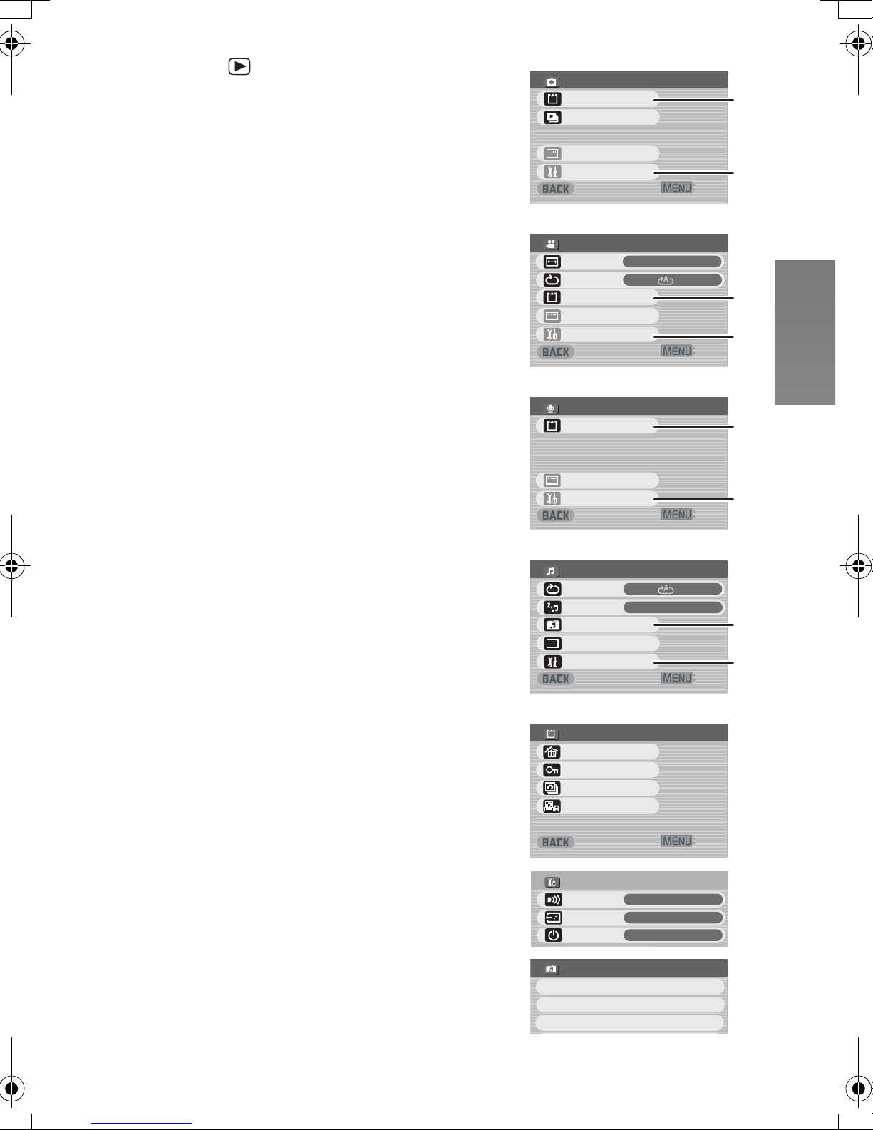
ª Play Mode [ ]
':+6
%#4&'&+6+0)
&21(TGUGVVKPI
'TCUGCNNHKNGU
.QEM7PNQEM
&21(EJGEMKPI
5'672
1P
᳆ᲽᲾ
$GGR
1WVRWVUGNGEV
#WVQRQYGTQP
1HH
':+6
2.#;/'07
&KURNC[UGVWR
%CTFGFKVKPI
25NKFGUJQY
5GVWR
ųųų
':+6
2.#;/'07
&KURNC[UGVWR
%CTFGFKVKPI
5GVWR
ųųų
':+6
2.#;/'07
(WNN
&KURNC[UGVWR
.%&UETGGP
4GRGCV
5GVWR
%CTFGFKVKPI
#NN
':+6
2.#;/'07
1P
&KURNC[UGVWR
4GRGCV
2QYGTUCXG
5GVWR
2NC[NKUV
2.#;.+56
&GHCWNV2NC[NKUV
2NC[NKUV
2NC[NKUV
#NN
1 Still Picture Playback Menu
Card editing [Card editing] 1
P. Slide show [P. Slide show] (l 37)
Display setup [Display setup] (l 18)
Initial setup [Setup] 2
Return to the previous screen [BACK]
2 MPEG4 Moving Picture Playback Menu
Playback size [LCD screen] (l 25)
≥Despite the setting, the display size on an
external device is limited to [Normal].
MPEG4 repeat [Repeat] (l 25)
Card editing [Card editing] 1
Display setup [Display setup] (l 18)
Initial setup [Setup] 2
Return to the previous screen [BACK]
3 Voice Playback Menu
Card editing [Card editing] 1
Display setup [Display setup] (l 18)
Initial setup [Setup] 2
Return to the previous screen [BACK]
4 Audio Playback Menu
Audio repeat [Repeat] (l 28)
Power save [Power save]
≥When it is set to [On], the LCD Monitor is turned
off in approx. 5 seconds after playing a music file.
Select playlist [Playlist] 3 (l 29)
Display setup [Display setup] (l 18)
Initial setup [Setup] 2
Return to the previous screen [BACK]
Sub-Menu for Play Mode
1 Card editing [Card editing]
Erase all files [Erase all files] (l 34)
File protection [Lock/Unlock] (l 35)
DPOF check [DPOF checking]* (l 36)
DPOF reset [DPOF resetting]* (l 36)
* Still Picture Playback Menu only.
Return to the previous screen [BACK]
2 Initial setup [Setup]
Beep sound setting [Beep] (l 18)
AV output selection [Output select] (l 39)
Auto power on [Auto power on] (l 15)
Return to the previous screen [BACK]
3 Select Playlist [Playlist]
Default playlist [DefaultPlaylist] (l 29)
Playlist [Playlist] (l 29)
1
2
3
4
1
2
3
2.#;/'07
%CTFGFKVKPI
25NKFGUJQY
ųųų
&KURNC[UGVWR
5GVWR
2.#;/'07
.%&UETGGP
4GRGCV
%CTFGFKVKPI
&KURNC[UGVWR
5GVWR
2.#;/'07
%CTFGFKVKPI
ųųų
&KURNC[UGVWR
5GVWR
2.#;/'07
4GRGCV
2QYGTUCXG
2NC[NKUV
&KURNC[UGVWR
5GVWR
%#4&'&+6+0)
'TCUGCNNHKNGU
.QEM7PNQEM
&21(EJGEMKPI
&21(TGUGVVKPI
ų
5'672
$GGR
1WVRWVUGNGEV
#WVQRQYGTQP
ų
2.#;.+56
&GHCWNV2NC[NKUV
2NC[NKUV
2NC[NKUV
1
2
':+6
(WNN
#NN
1
2
':+6
1
2
':+6
#NN
1P
3
2
':+6
':+6
1P
᳆ᲽᲾ
1HH
19
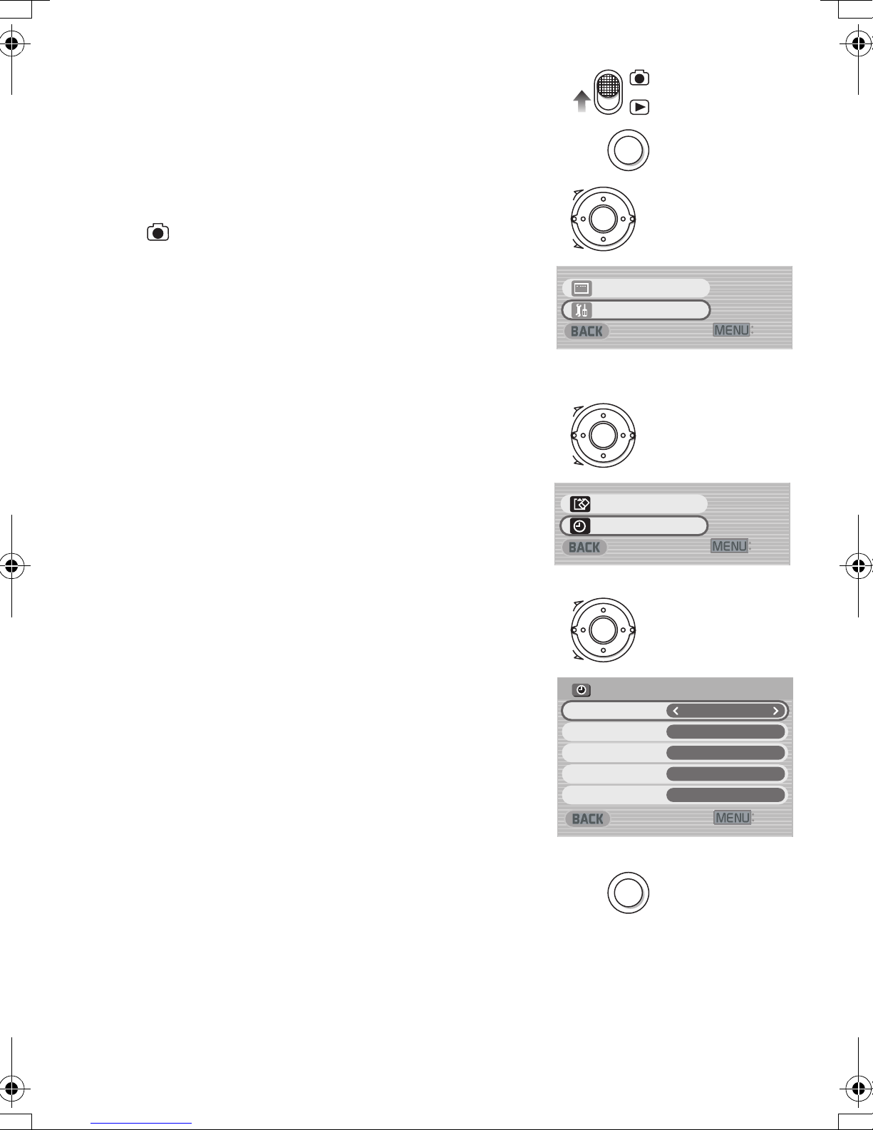
Setting Date and Time
':+6
&KURNC[UGVWR
5GVWR
':+6
(QTOCVECTF
%NQEMUGV
MENU
':+6
%.1%-5'6
;GCT
/QPVJ
&C[
*QWT
/KPWVG
MENU
At the time of purchase of the SD Video Camera, the
date and time are not set ([PRESS MENU TO SET
CLOCK] is displayed). First, set the date and time,
then use the SD Video Camera.
1
2
MENU
1 Set the Record/Play mode Switch to
[].
2 Press the [MENU] Button.
3 Select [Setup] and press the Jog Ball.
4 Select [Clock set] and press the Jog Ball.
5 Select [Year] and roll the Jog Ball LEFT or
RIGHT to set a desired value.
6 In the same way, set [Month], [Day],
[Hour], [Minute] to a desired value.
7 Press the [MENU] Button.
≥The time format is a 24 hour clock.
≥When the built-in battery has been exhausted, set
the date and time after the battery has charged.
(l 49)
3
4
5,6
Ô
×
ų
&KURNC[UGVWR
5GVWR
Ô
×
ų
(QTOCVECTF
%NQEMUGV
Ô
':+6
':+6
20
7
×
%.1%-5'6
;GCT
/QPVJ
&C[
*QWT
/KPWVG
MENU
':+6
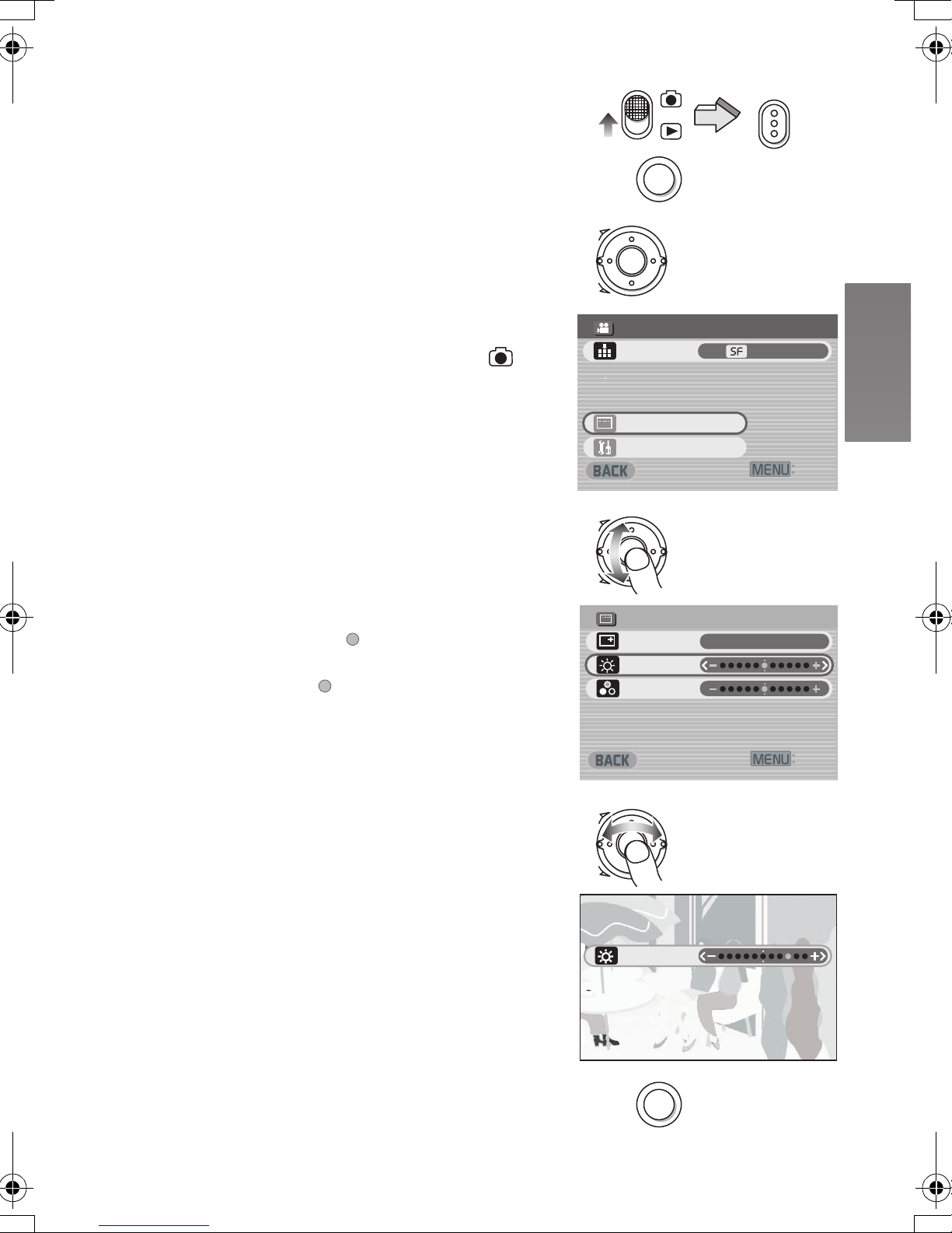
Adjusting Brightness and
#WVQTGEQTFKPIUGVWR
':+6
4'%/'07
&KURNC[UGVWR
5GVWR
5WRGTHKPG
/2')OQFG
MENU
MODE
':+6
&+52.#;5'672
1P
+EQPFKURNC[
$TKIJVPGUU
%QNQWT
$TKIJVPGUU
MENU
Colour Level on the LCD
Monitor
1
MODE
LCD Brightness [Brightness]
It adjusts the brightness of the image on the LCD
screen.
LCD Colour Level [Colour]
It adjusts the colour saturation of the image on the
LCD screen.
1 Set the Record/Play mode Switch to [ ]
and set the operation mode to [PICTURE]
or [MPEG4].
2 Press the [MENU] Button.
3 Select [Display setup] and press the Jog
Ball.
4 Select [Brightness] or [Colour].
5 Roll the Jog Ball LEFT or RIGHT for
adjustment.
≥If [Brightness] is selected, the brightness can be
increased by moving the [ ] to the right.
≥If [Colour] is selected, the colour can become
darker by moving the [ ] to the right.
≥If left unused for approx. 5 seconds, the display
will automatically revert to the [Display setup]
screen.
6 Press the [MENU] Button.
≥The [MENU] screen disappears.
2
3
4
5
MENU
Ô
×
4'%/'07
/2')OQFG
#WVQTGEQTFKPIUGVWR
ų
&KURNC[UGVWR
5GVWR
Ô
×
&+52.#;5'672
+EQPFKURNC[
$TKIJVPGUU
%QNQWT
Ô
5WRGTHKPG
':+6
1P
':+6
≥These adjustments do not affect the recorded
images.
6
×
$TKIJVPGUU
MENU
21
 Loading...