

Panasonic SC-PT953, SCPT950, SCPT1050 User Manual
Region number
The player plays DVD-Video marked with labels containing the region
number “1” or “ALL”.
Example:
1 ALL
1
2
4
Operating Instructions
DVD Home Theater Sound System
Model No. SC-PT950
SC-PT1050
SC-PT953
The illustration shows SC-PT950.
Wireless surround
speakers
[PT1050]
Wireless subwoofer
5
[U.S.A.[and[Canada[
As an ENERGY STAR Partner,
Panasonic has determined that
this product meets the ENERGY STAR
guidelines for energy efficiency.
§
For Canada only: The word “Participant” is used in place of the word
“Partner”.
P PC
PX
®
®
High-quality picture
HDMI capability, Advanced
progressive scan and more.
7
XM® Satellite Radio
Enjoy a variety of digital radio
channels.
30
Before connecting, operating or adjusting this product, please
read the instructions completely.
Please keep this manual for future reference.
If you have any questions contact
In the U.S.A.: 1-800-211-PANA (7262)
In Canada: 1-800-561-5505
RQTX0064-3P
Dear customer
Thank you for purchasing this product. For optimum performance and
safety, please read these instructions carefully.
≥ These operating instructions are applicable to models SC-PT950,
SC-PT953 and SC-PT1050 for a variety of regions.
≥ Unless otherwise indicated, illustrations in these operating
instructions are of SC-PT950 for U.S.A. and Canada.
≥ Operations in these instructions are described mainly with the
remote control, but you can perform the operations on the main
unit if the controls are the same.
CAUTION!
THIS PRODUCT UTILIZES A LASER.
USE OF CONTROLS OR ADJUSTMENTS OR PERFORMANCE OF
PROCEDURES OTHER THAN THOSE SPECIFIED HEREIN MAY
RESULT IN HAZARDOUS RADIATION EXPOSURE.
DO NOT OPEN COVERS AND DO NOT REPAIR YOURSELF.
REFER SERVICING TO QUALIFIED PERSONNEL.
WARNING:
TO REDUCE THE RISK OF FIRE, ELECTRIC SHOCK
OR PRODUCT DAMAGE,
≥
DO NOT EXPOSE THIS APPARATUS TO RAIN,
MOISTURE, DRIPPING OR SPLASHING AND THAT
NO OBJECTS FILLED WITH LIQUIDS, SUCH AS
VASES, SHALL BE PLACED ON THE APPARATUS.
≥
USE ONLY THE RECOMMENDED ACCESSORIES.
≥
DO NOT REMOVE THE COVER (OR BACK); THERE
ARE NO USER SERVICEABLE PARTS INSIDE. REFER
SERVICING TO QUALIFIED SERVICE PERSONNEL.
THE FOLLOWING APPLIES ONLY IN THE U.S.A. AND CANADA
(For wireless system)
The following mark and symbols are located on bottom of the unit.
IMPORTANT SAFETY INSTRUCTIONS
CAUTION: TO REDUCE THE RISK OF ELECTRIC
CAUTION
RISK OF ELECTRIC SHOCK
DO NOT OPEN
SHOCK, DO NOT REMOVE SCREWS.
NO USER-SERVICEABLE PARTS INSIDE.
REFER SERVICING TO QUALIFIED
SERVICE PERSONNEL.
The lightning flash with arrowhead symbol, within
an equilateral triangle, is intended to alert the user
to the presence of uninsulated “dangerous voltage”
within the product’s enclosure that may be of
sufficient magnitude to constitute a risk of electric
shock to persons.
The exclamation point within an equilateral triangle
is intended to alert the user to the presence of
important operating and maintenance (servicing)
instructions in the literature accompanying the
appliance.
[PT950] : indicates features applicable to SC-PT950 only.
[PT953] : SC-PT953 only
[PT1050] : SC-PT1050 only
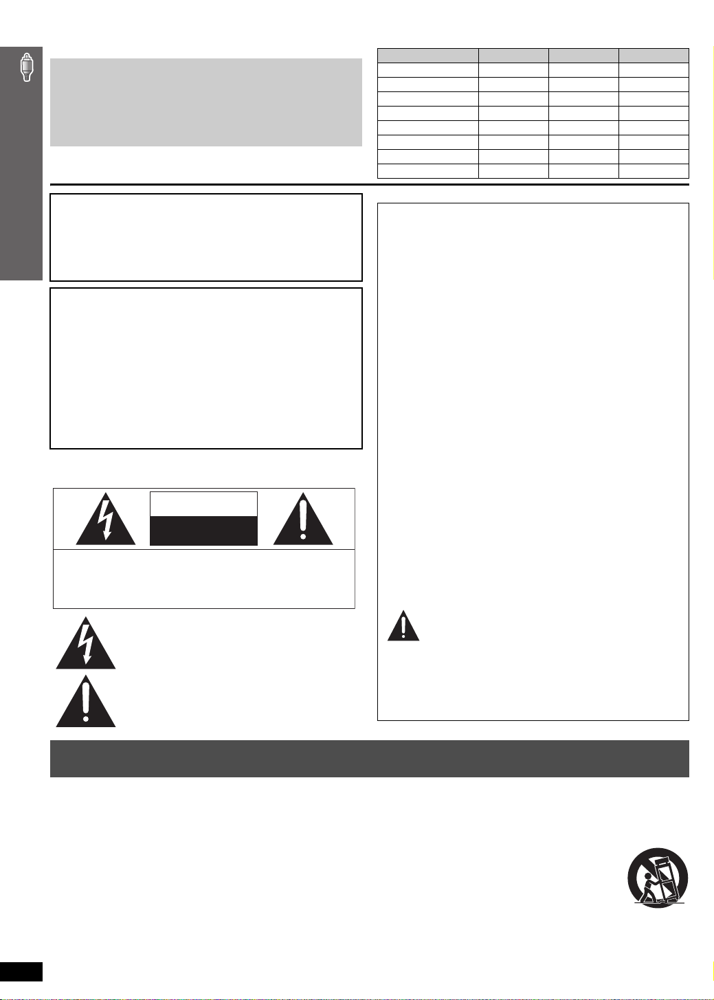
System SC-PT950 SC-PT953 SC-PT1050
Main unit SA-PT950 SA-PT953 SA-PT1050
Front speakers SB-HF950 SB-HF950 SB-HF1050
Center speaker SB-HC950 SB-HC950 SB-HC950
Surround speakers SB-HS950 SB-HS950 SB-HS1050
Subwoofer SB-HW950 SB-HW950 s
Active subwoofer ssSB-WA1050
Digital transmitter SH-FX65T SH-FX65T SH-FX65T
Wireless system SE-FX65 SE-FX65 SE-FX66
THE FOLLOWING APPLIES ONLY IN THE U.S.A.
FCC Note:
This equipment has been tested and found to comply with the limits
for a Class B digital device, pursuant to Part 15 of the FCC Rules.
These limits are designed to provide reasonable protection against
harmful interference in a residential installation. This equipment
generates, uses and can radiate radio frequency energy and, if not
installed and used in accordance with the instructions, may cause
harmful interference to radio communications.
However, there is no guarantee that interference will not occur in a
particular installation. If this equipment does cause harmful
interference to radio or television reception, which can be determined
by turning the equipment off and on, the user is encouraged to try to
correct the interference by one or more of the following measures:
≥ Reorient or relocate the receiving antenna.
≥ Increase the separation between the equipment and receiver.
≥ Connect the equipment into an outlet on a circuit different from that
to which the receiver is connected.
≥ Consult the dealer or an experienced radio/TV technician for help.
FCC caution: To maintain compliance with FCC regulations, shielded
interface cables must be used with this equipment. Operation with
non-approved equipment or unshielded cables may result in
interference to radio and TV reception. Any changes or modifications
not approved by the party responsible for compliance could void the
user’s authority to operate this equipment.
This device complies with Part 15 of the FCC Rules.
Operation is subject to the following two conditions:
(1) This device may not cause harmful interference, and
(2) this device must accept any interference received, including
interference that may cause undesired operation.
Responsible Party:
Panasonic Corporation of North America
One Panasonic Way
Secaucus, NJ 07094
Support Contact:
Panasonic Consumer Electronics Company
Telephone No.: 1-800-211-7262
WARNING:
To satisfy FCC RF exposure requirements for mobile transmitting
devices, a separation distance of 20 cm or more should be maintained
between the antenna of this device and persons during device
operation. To ensure compliance, operations at closer than this
distance is not recommended. The antenna used for this transmitter
must not be co-located in conjunction with any other antenna or
transmitter.
IMPORTANT SAFETY INSTRUCTIONS
Read these operating instructions carefully before using the unit. Follow the safety instructions on the unit and the applicable safety instructions listed
below. Keep these operating instructions handy for future reference.
1) Read these instructions.
2) Keep these instructions.
3) Heed all warnings.
4) Follow all instructions.
5) Do not use this apparatus near water.
6) Clean only with dry cloth.
7) Do not block any ventilation openings. Install in accordance with the
manufacturer’s instructions.
8) Do not install near any heat sources such as radiators, heat registers,
stoves, or other apparatus (including amplifiers) that produce heat.
9) \U.S.A.\and\Canada]
Do not defeat the safety purpose of the polarized or grounding-type
plug. A polarized plug has two blades with one wider than the other.
A grounding-type plug has two blades and a third grounding prong.
RQTX0064
The wide blade or the third prong are provided for your safety. If the
2
provided plug does not fit into your outlet, consult an electrician for
replacement of the obsolete outlet.
10) Protect the power cord from being walked on or pinched particularly
at plugs, convenience receptacles, and the point where they exit from
the apparatus.
11) Only use attachments/accessories specified by the manufacturer.
12) Use only with the cart, stand, tripod, bracket, or table
specified by the manufacturer, or sold with the
apparatus. When a cart is used, use caution when
moving the cart/apparatus combination to avoid injury
from tip-over.
13) Unplug this apparatus during lightning storms or when
unused for long periods of time.
14) Refer all servicing to qualified service personnel. Servicing is
required when the apparatus has been damaged in any way, such as
power-supply cord or plug is damaged, liquid has been spilled or
objects have fallen into the apparatus, the apparatus has been
exposed to rain or moisture, does not operate normally, or has been
dropped.
TABLE OF CONTENTS
Getting
Started
Playing
Discs
IMPORTANT SAFETY INSTRUCTIONS . . . . . . . 2
Simple Setup
step 1
step 2
step 3
step 4
Basic play. . . . . . . . . . . . . . . . . . . . . . . . . . . . . . 16
Using the main unit . . . . . . . . . . . . . . . . . . . . . . . . . . . 16
Using the remote control . . . . . . . . . . . . . . . . . . . . . . 17
Convenient functions . . . . . . . . . . . . . . . . . . . . 18
Checking and selecting the disc . . . . . . . . . . . . . . . . . 18
Displaying current playback condition. . . . . . . . . . . . . 18
Playing CDs sequentially . . . . . . . . . . . . . . . . . . . . . . 18
Repeat play. . . . . . . . . . . . . . . . . . . . . . . . . . . . . . . . . 18
[PT950] [PT953] Quick replay . . . . . . . . . . . . . . . . . . . . 18
Program and Random play . . . . . . . . . . . . . . . . . . . . . 19
Assembling the front speakers . . . .4
Positioning . . . . . . . . . . . . . . . . . . . . .5
Speaker installation options . . . . . . . . . . . . . 6
Cable connections. . . . . . . . . . . . . . . 7
Audio and video connections . . . . . . . . . . . . 7
Speaker connections . . . . . . . . . . . . . . . . . . 8
Radio antenna connections . . . . . . . . . . . . . 8
Digital transmitter connection . . . . . 9
step 5
step 6
step 7
step 8
Control reference guide . . . . . . . . . . . . . . . . . 12
Discs that can be played. . . . . . . . . . . . . . . . . 14
Maintenance. . . . . . . . . . . . . . . . . . . . . . . . . . . 15
Playing data discs using navigation menus . .20
Playing data discs . . . . . . . . . . . . . . . . . . . . . . . . . . . 20
Selecting a track using CD text . . . . . . . . . . . . . . . . . 20
Playing HighMAT
Playing RAM and DVD-R/ -RW (DVD-VR) discs . . . . 21
Using on-screen menus . . . . . . . . . . . . . . . . . . 22
Main menu . . . . . . . . . . . . . . . . . . . . . . . . . . . . . . . . . 22
Other Settings . . . . . . . . . . . . . . . . . . . . . . . . . . . . . . 23
Changing the player settings . . . . . . . . . . . . . .25
Changing the delay time of the speakers. . . . . . . . . . 27
iPod connection. . . . . . . . . . . . . . . 10
AC cord connections. . . . . . . . . . . 10
Preparing the remote control . . . . 11
Performing QUICK SETUP . . . . . . 11
TM
discs . . . . . . . . . . . . . . . . . . . . . . 21
Other
Operations
Reference
Using the EZ Sync
One touch play . . . . . . . . . . . . . . . . . . . . . . . . . . . . . . 28
Auto input switching . . . . . . . . . . . . . . . . . . . . . . . . . . 28
Speaker control . . . . . . . . . . . . . . . . . . . . . . . . . . . . . 28
Power off link . . . . . . . . . . . . . . . . . . . . . . . . . . . . . . . 28
EZ Sync Control only with TV’s remote control
(for “HDAVI Control 2”). . . . . . . . . . . . . . . . . . . . . . . 28
Using the FM/AM radio . . . . . . . . . . . . . . . . . . . 29
Presetting stations automatically . . . . . . . . . . . . . . . . 29
Selecting the preset channels . . . . . . . . . . . . . . . . . . 29
Manual tuning . . . . . . . . . . . . . . . . . . . . . . . . . . . . . . . 29
Using the XM® Satellite Radio . . . . . . . . . . . . . 30
Selecting XM channels by direct entry . . . . . . . . . . . . 31
Selecting XM channels by category . . . . . . . . . . . . . . 31
Presetting the XM channels . . . . . . . . . . . . . . . . . . . . 31
Using sound effects . . . . . . . . . . . . . . . . . . . . .32
Using the equalizer function . . . . . . . . . . . . . . . . . . . . 32
Enjoying sound from all speakers: Surround Music . . . 32
Glossary . . . . . . . . . . . . . . . . . . . . . . . . . . . . . . .35
Product Service . . . . . . . . . . . . . . . . . . . . . . . . .35
Troubleshooting guide . . . . . . . . . . . . . . . . . . . 36
Specifications . . . . . . . . . . . . . . . . . . . . . . . . . .40
TM
“HDAVI ControlTM” . . . . . 28
Enhancing the sound from the center speaker:
Center Focus. . . . . . . . . . . . . . . . . . . . . . . . . . . . . . 32
Enhancing the stereo sound:
Dolby Pro Logic II/Super Surround . . . . . . . . . . . . . 32
Adjusting the amount of bass: Subwoofer level . . . . . 32
Adjusting the volume of each speaker: Speaker level
adjustments. . . . . . . . . . . . . . . . . . . . . . . . . . . . . . . 33
[PT1050] Enhancing the bass sound: H.BASS . . . . . . 33
[PT1050] Enhancing the surround sound effect:
Surround Enhancer . . . . . . . . . . . . . . . . . . . . . . . . . 33
Adjusting the speaker output level automatically:
Auto Speaker Setup . . . . . . . . . . . . . . . . . . . . . . . . 33
Enjoying audio from an external source . . . . .34
Enjoying audio from the television . . . . . . . . . . . . . . . 34
Using the Music Port . . . . . . . . . . . . . . . . . . . . . . . . . 34
Using the iPod . . . . . . . . . . . . . . . . . . . . . . . . . . . . . . 34
[PT1050] Operating the cable TV box,
digital broadcasting or satellite receiver . . . . . . . . . 34
Limited Warranty (ONLY FOR U.S.A.) . . . . . . . 42
Limited Warranty (ONLY FOR CANADA). . . . . 43
Accessories . . . . . . . . . . . . . . . . . . . . Back cover
RQTX0064
3
step
1
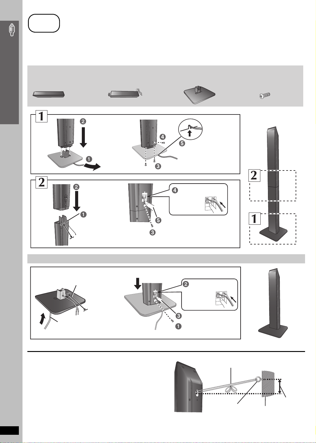
Assembling the front speakers
Preparation
≥ To prevent damage or scratches, lay down a soft cloth and perform assembly on it.
≥ For assembly, use a Phillips-head screwdriver.
≥ There is no difference between the right and left speakers and stands.
≥ For optional wall mount, refer to page 6.
Simple Setup
Assembling the front speakers
Make sure you have all the indicated components before starting assembly, setup, and connection.
2 Front speakers 2 Stands (with cable) 2 Bases
Slide into the groove.
Tighten securely.
Insert the wire fully.
i: White
j: Blue
Push !
Position the cable
between the ridges.
Leave about 80 mm (3
5
/16z)
Press into the groove.
Tighten securely.
8 Screws
Speaker assembly option
Thread the speaker cable through
the base.
Leave about 100 mm (315/16z)
You can remove and use the cable from
the stand. To reattach the cable, refer to
page 6.
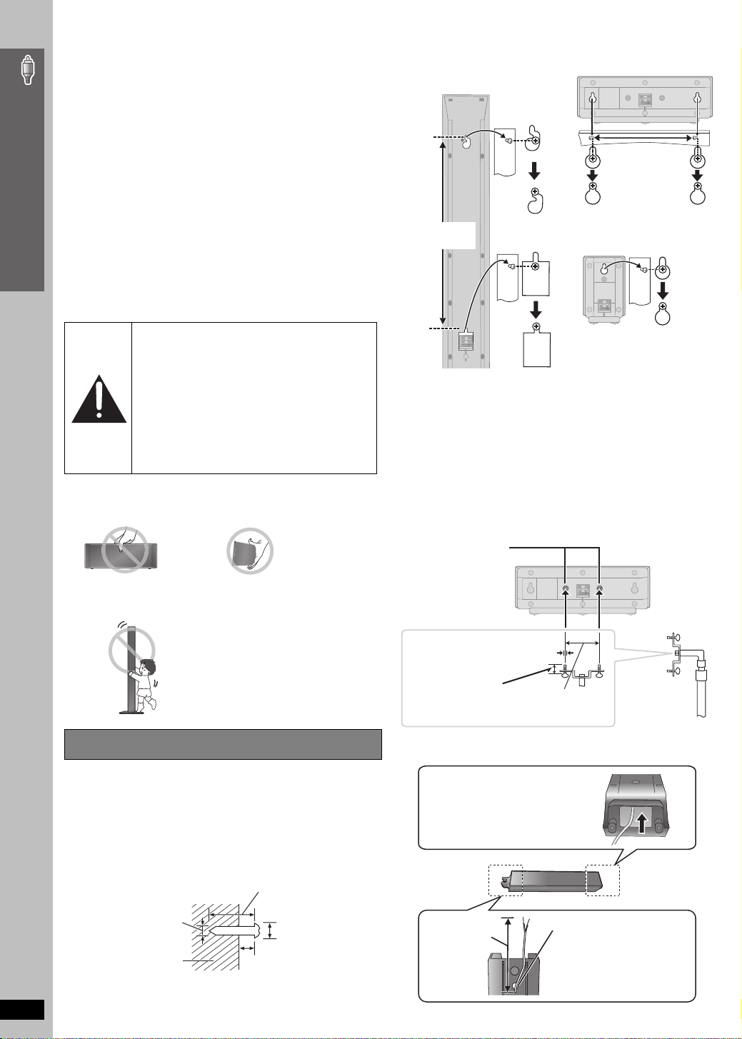
∫ Preventing the speakers from falling
≥ You will need to obtain the appropriate screw eyes to match the
walls or pillars to which they are going to be fastened.
≥ Consult a qualified housing contractor concerning the
appropriate procedure when attaching to a concrete wall or a
surface that may not have strong enough support. Improper
attachment may result in damage to the wall or speakers.
RQTX0064
Attach the speaker.
Insert the wire fully.
i: White
j: Blue
Push !
Press into the groove.
Tighten securely.
String (not included)
Thread from the wall to the speaker and tie tightly.
Rear of the speaker
Screw eye
(not included)
Wall
Approx.
150 mm
29
/32z)
(5
4
step
2
Positioning
How you set up your speakers can affect the bass and the sound field. Note the following points:
≥ Place speakers on flat secure bases.
≥ Placing speakers too close to floors, walls, and corners can result in excessive bass. Cover walls and windows with thick curtains.
≥ For optional wall mount, refer to page 6.
[Note]
Keep your speakers at least 10 mm (13/32q) away from the system for proper ventilation.
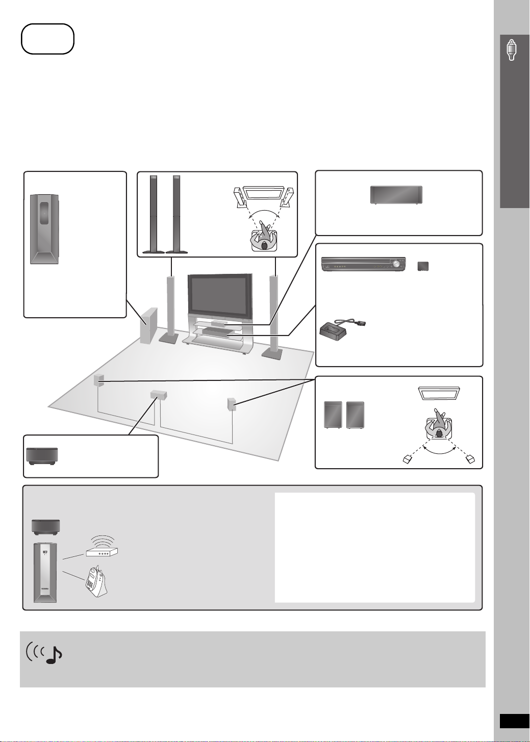
Setup example
Place the front, center, and surround speakers at approximately the same distance from the seating position. Using “Auto Speaker Setup”
(➜ page 33) is a convenient way to get the ideal surround sound from your speakers when you are unable to place them an equal distance away
from the seating position. The angles in the diagram are approximate.
Simple Setup
[PT950] [PT953] Subwoofer
[PT1050] Wireless subwoofer
e.g. [PT950] [PT953]
Place to the right or left of the
television, on the floor or a
sturdy shelf so that it will not
cause vibration. Leave about
30 cm (11
television.
§
13
/16q) from the
Do not use the wireless
equipment in a metal
cabinet or bookshelf.
Wireless system
Place the wireless system
within approximately 10 m
(33 ft) from the main unit.
§
Front speakers
Left and right
speakers are
interchangeable.
60º
Put on a rack or shelf. Vibration caused by the
speaker can disrupt the picture if it is placed
directly on the television.
Main unit
Center speaker
Digital transmitter
§
Positioning
To allow for proper ventilation and to maintain
good airflow around the main unit, position it with
at least 5 cm (2q) of space on all sides.
Universal Dock for iPod
(included only for SC-PT950
and SC-PT1050)
Position near the main unit.
≥ For compatible iPod, refer to
page 34.
Surround speakers
e.g. [PT950] [PT953]
§
Left and right speakers are
interchangeable.
120º
To avoid interference, maintain the following distances
between the wireless equipment and other electronic
devices that use the same radio frequency (2.4 GHz band).
POWER
AUTO OPERATION
ON/OFF
Wireless LAN:
approx. 2 m (6-1/2 ft)
Cordless phone and other
electronic devices:
approx. 2 m (6-1/2 ft)
The wireless equipment will automatically seek a clear
channel if any of these other devices interfere with its
communication. When this happens, the wireless link
indicator [“ [W1] ” or “ [WS] ([PT1050] only)”] flashes on the
main unit, and there is a brief interruption in audio coming
from the surround speakers.
This is the normal operation of the product working to assure
the best possible performance of your home theater system.
If the interference persists, try moving the other devices to
another location outside the range of the wireless equipment
or move the wireless equipment nearer to the main unit.
Expand your listening options with a multi-room wireless sound system.
Optional Panasonic wireless accessory SH-FX85
You can enjoy a multi-room wireless sound system when you use the optional Panasonic wireless accessory SH-FX85.
For details, please refer to the operating instructions for the optional Panasonic wireless accessory.
(Continued on next page)
RQTX0064
5
Notes on speaker use
≥Use only supplied speakers
Using other speakers can damage the unit, and sound quality will be
negatively affected.
≥ You can damage your speakers and shorten their useful life if you play
sound at high levels over extended periods.
≥ Reduce the volume in the following cases to avoid damage:
– When playing distorted sound.
– When the speakers are reverberating due to a record player, noise
Simple Setup
from FM broadcasts, or continuous signals from an oscillator, test
disc, or electronic instrument.
– When adjusting the sound quality.
– When turning the unit on or off.
2 Fit the speaker securely onto the screw(s) with the hole(s).
Front speaker
Attach to a wall without the
base and the stand
Center speaker
190 mm
(7
15
/32q)
If irregular coloring occurs on your television
The front and center speakers are designed to be used close to a
television, but the picture may be affected with some televisions and
setup combinations.
If this occurs, turn the television off for about 30 minutes.
The demagnetizing function of the television should correct the problem.
If it persists, move the speakers further away from the television.
Caution
≥ The main unit and supplied speakers are to be
Positioning
used only as indicated in this setup. Failure to
do so may lead to damage to the amplifier and/
or the speakers, and may result in the risk of
fire. Consult a qualified service person if
damage has occurred or if you experience a
sudden change in performance.
≥ Do not attempt to attach these speakers to
walls using methods other than those
described in this manual.
Caution
≥ Do not touch the front netted area of the speakers. Hold by the sides.
e.g. Center speaker
≥ Do not stand on the base. Be cautious when children are near.
e.g. Front speaker
384 mm
1
(15
/8q)
e.g. [PT950] [PT953]
Surround speaker
∫ Fitting speaker stands (not included)
(except front speakers and subwoofer)
Ensure the stands meet these conditions before purchasing them.
Note the diameter and length of the screws and the distance
between screws as shown in the diagram.
≥ The stands must be able to support over 10 kg (22 lbs).
≥ The stands must be stable even if the speakers are in a high
position.
e.g. Center speaker
Metal screw holes
For attaching to
speaker stands
3
5 mm (
/16q), pitch 0.8 mm (1/32q)
Speaker installation options
∫ Attaching to a wall
You can attach all of the speakers (except subwoofer) to a wall.
The wall or pillar on which the speakers are to be attached should be
≥
capable of supporting 10 k
g
(22 lbs) per screw. Consult a qualified
Plate thickness plus
7 mm to 10 mm
9
/32q to 13/32q)
(plus
60 mm (2
∫ Reattaching the front speaker cable
Insert the cable from
the bottom.
3
/8q)
Speaker stand
(not included)
building contractor when attaching the speakers to a wall. Improper
attachment may result in damage to the wall and speakers.
1 Drive a screw (not included) into the wall.
At least 30 mm (1
5
‰4.0 mm (
RQTX0064
/32q)
Wall or pillar
‰7.0 t o 9.4 mm
9
(
4 to 6 mm (
/32q to 11/32q)
5
/32q to 1/4q)
3
/16q)
Leave about
5
80 mm (3
/16z)
Pull out the cable
through the hole.
6
step
.
3
Cable connections
Turn off all equipment before connection and read the appropriate operating instructions.
Do not connect the AC power supply cord until all other connections are complete.
1
COMPONENT VIDEO OUT
AUX
PBY
L
R
VIDEO
R
P
OUT
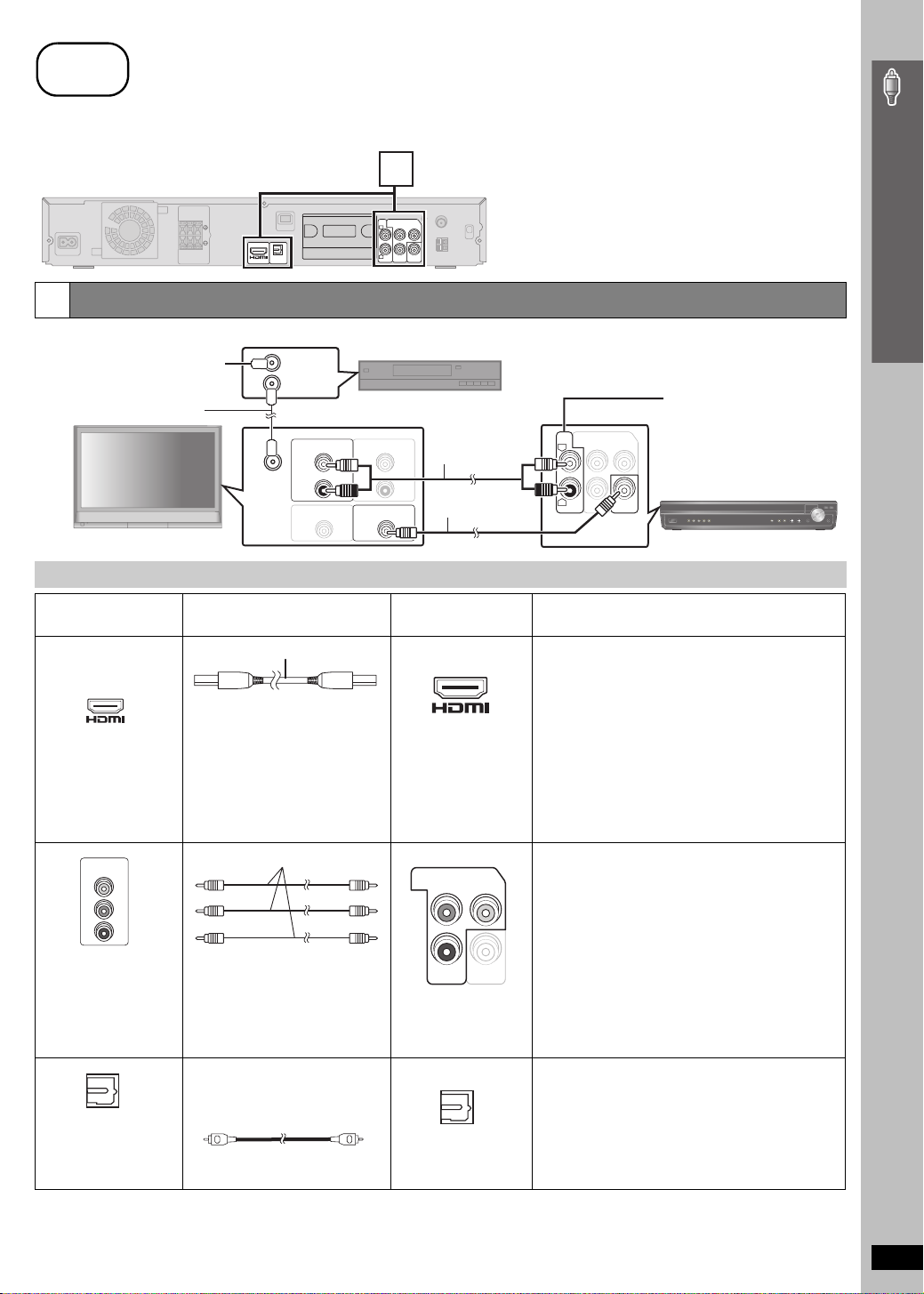
Audio and video connections
1
OPTICAL
AV OUT
IN
Basic setup example
To your cable TV service or
television antenna
RF IN
RF OUT
Cable TV box or video cassette recorder (not included)
RF cable (not included)
Audio cable
(not included)
Video cable
(included)
RF IN
AUDIO OUT
L
R
AUDIO IN
L
R
VIDEO INVIDEO OUT
Television (not included)
Other connections for improved picture and audio quality
Television terminals
AV IN
COMPONENT
VIDEO IN
Y
PB
PR
All Panasonic televisions
that have 480p input
connectors are
compatible. Consult the
manufacturer if you have
another brand of
television.
OPTICAL OUT
[Note]
≥Do not make the video connections through the video cassette recorder.
≥ Only one video connection is required.
Cables required
(not included)
HDMI cable
[Note]
≥ Non-HDMI-compliant cables
cannot be utilized.
≥ It is recommended that you use
Panasonic’s HDMI cable.
Recommended part number:
RP-CDHG15 (1.5 m/4.9 ft),
RP-CDHG30 (3.0 m/9.8 ft),
RP-CDHG50 (5.0 m/16.4 ft), etc.
Video cables
Optical digital audio cable
(not included)
≥
Do not bend sharply when connecting
Main unit terminals Features
[\\\\\\\\\\\HDMI\\\\\\\\\\\]
AV OUT
[COMPONENT\VIDEO]
COMPONENT VIDEO OUT
PBY
R
P
≥ Connect to terminals
of the same color.
[OPTICAL\IN]
[PT1050]
OPTICAL
IN
Main unit
(The illustration shows SC-PT1050.)
You can enjoy audio from your
television, video cassette
AUX
COMPONENT VIDEO OUT
PBY
L
R
P
R
recorder or cable TV programs
through this home theater
system by connecting to the
AUX terminals. Select “AUX”
as the source (➜ page 34).
VIDEO
OUT
Main unit
This connection provides the best picture quality.
≥ Set “Video Mode” to “On” (➜ page 26, “HDMI” menu).
≥ Set “Video Output Mode” (➜ page 23, Picture Menu).
EZ Sync “HDAVI Control”
If your Panasonic television is an HDMI control
compatible television, you can operate your television
synchronizing with home-theater operations or vice
versa (➜ page 28, Using the EZ Sync
TM
”).
Control
≥ Make the audio connection (➜ above) when you use
EZ Sync “HDAVI Control” function.
This connection provides a much purer picture than the
VIDEO OUT terminal.
≥ After making this connection, select “Darker” from the
“Black Level Control” in the “Video” menu
(➜ page 26).
To enjoy progressive video
VIDEO
OUT
≥ Connect to a progressive output compatible
television.
1 Set “Video Mode” to “Off” (➜ page 26, “HDMI”
menu).
2
Set “
Video Output Mode
the instructions on the menu screen
Picture Menu).
This unit can decode the surround signals received
through cable TV box, digital broadcasting or satellite
broadcasts. Refer to your equipment’s operating
instructions for details. Only Dolby Digital and PCM can
be played with this connection.
≥ After making this connection, make settings and
select sound effects to suit your digital equipment
(➜ page 34).
Due to copy guard protection, the picture may not be displayed properly.
(Continued on next page)
TM
“HDAVI
” to “480p”, and then follow
(➜ page 23,
Simple Setup
Cable connections
RQTX0064
7
step
3
Cable connections
Simple Setup
Cable connections
Wireless system
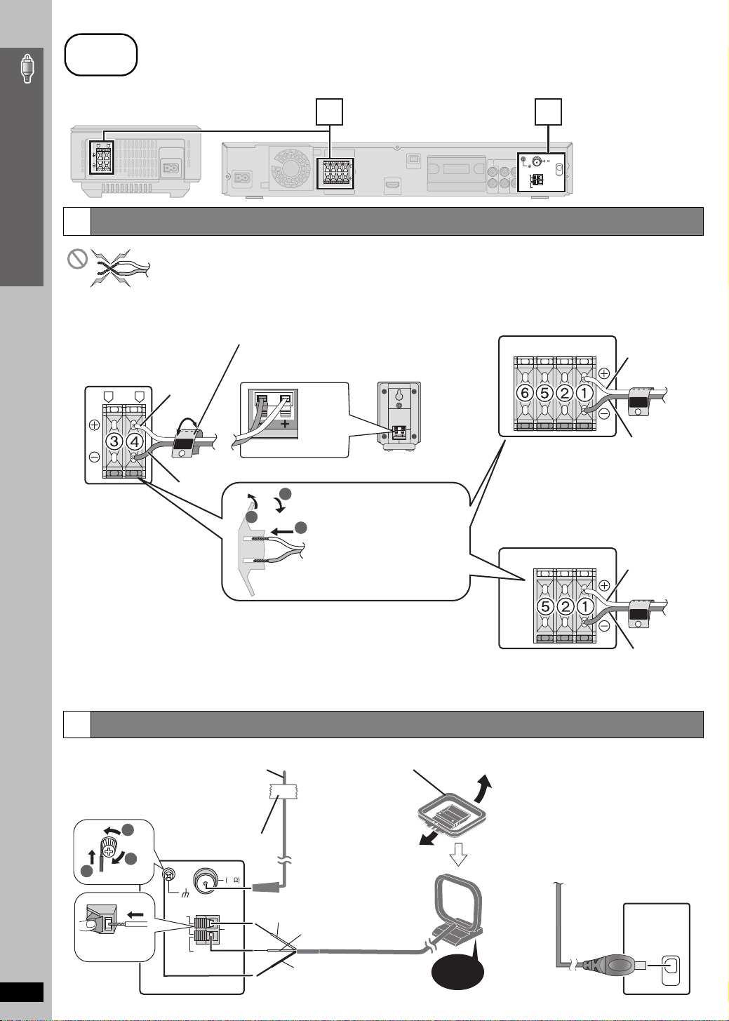
Speaker connections
2
Wireless system
Insert the wires
correctly.
3 SURROUND (L)
4 SURROUND (R)
2
3
FM ANT
FM ANT
Main unit
75
75
LOOP
LOOP
ANT GND
ANT GND
LOOP
LOOP
EXT
EXT
(The illustration shows
XM
XM
AM
AM
SC-PT950 for U.S.A.
ANT
ANT
and Canada.)
≥Be careful not to cross (short-circuit) or reverse the polarity of the speaker wires as doing so may damage the
speakers.
Speaker cable sticker (included)
Attach the corresponding speaker cables with the speaker-cable
[PT950] [PT953] Main unit
stickers to make connection easier.
e.g. [PT950] [PT953]
i: White
Surround speaker (R)
i: White
SURROUND
Rch
4
j: Blue
i: White
j: Blue
Insert the wires correctly.
1 FRONT (L)
2 FRONT (R)
3
1
2
Insert the wires, taking care not to
insert beyond the wire insulation.
5 CENTER
6 SUBWOOFER
[PT1050] Main unit
FRONT
Lch
1
j: Blue
i: White
FRONT
Lch
1
Insert the wires correctly.
1 FRONT (L)
2 FRONT (R)
j: Blue
5 CENTER
Radio antenna connections
3
≥ Keep loose antenna cables away from other wires and cables.
[FM\indoor\antenna]
(included)
Affix this end of the
antenna where
reception is best.
1
Adhesive tape
[AM\loop\antenna]
(included)
Stand the antenna
up on its base.
Place the antenna
where reception is
best.
3
2
ANT GND
LOOP
Push!
RQTX0064
LOOP
EXT
FM ANT
75
AM
ANT
White
Black
Red
Click!
[XM\antenna]
(not included)
Use an XM Connect & Play antenna,
or XM Passport Mini-Tuner and
Home Dock.
≥ Subscription is required to receive
XM Satellite Radio.
Refer to page 30 for details.
XM
8
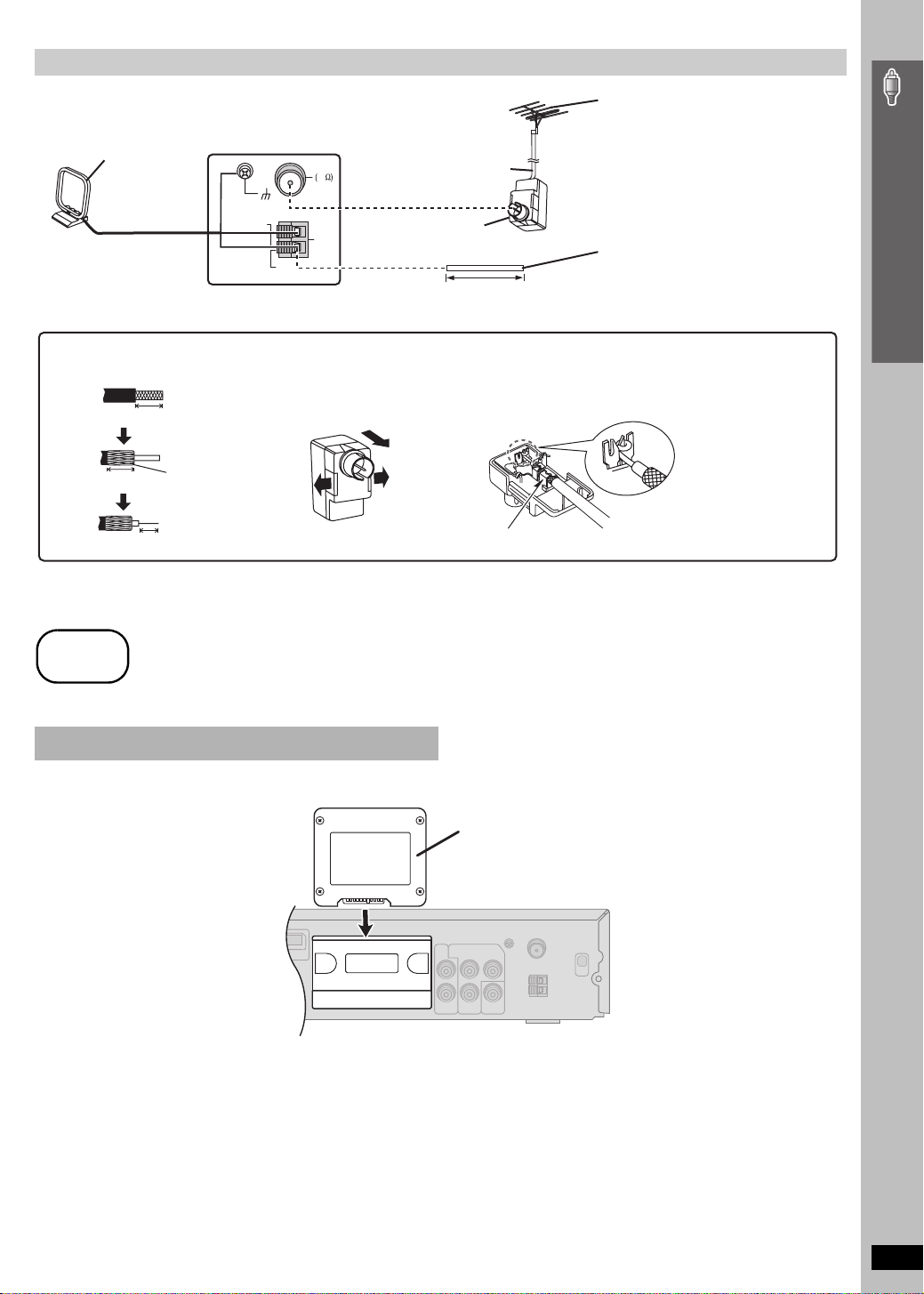
Using an FM/AM outdoor antenna (optional)
Use outdoor antenna if FM/AM radio reception is poor.
≥ Disconnect the antenna when the unit is not in use.
≥ Do not use the outdoor antenna during an electrical storm.
Leave the AM
loop antenna
connected.
ANT GND
LOOP
§
Rework your outdoor antenna’s 75 ≠ coaxial cable as follows.
1 Remove a piece of the outer
vinyl insulator.
13
10 mm (
13
/32z)
10 mm (
7 mm (
/32z)
Peel back
9
/32z)
FM ANT
75
LOOP
AM
ANT
EXT
2 Carefully pull the tabs apart
to remove the cover.
75 ≠ coaxial cable
(not included)
\U.S.A.\and\Canada]
Antenna plug (not included)
(16 to 39 feet)
§
5 to 12 m
3 Install the coaxial cable.
Clamp the cable conductor, and
wind it on so that it does not
contact anything else.
Clamp with pliers
FM outdoor antenna
[Using a television antenna (not
included)]
≥ Disconnect the FM indoor antenna.
≥ The antenna should be installed by a
competent technician.
AM outdoor antenna
[Using a vinyl wire (not included)]
Run a piece of vinyl wire horizontally across
a window or other convenient location.
4 Attach the cover.
Simple Setup
step
4
Digital transmitter connection
Do not insert or remove while the main unit is on.
DIGITAL
TRANSMITTER
AV OUT
Cable connections / Digital transmitter connection
Digital transmitter
Insert fully until you hear a click.
Main unit
RQTX0064
9
step
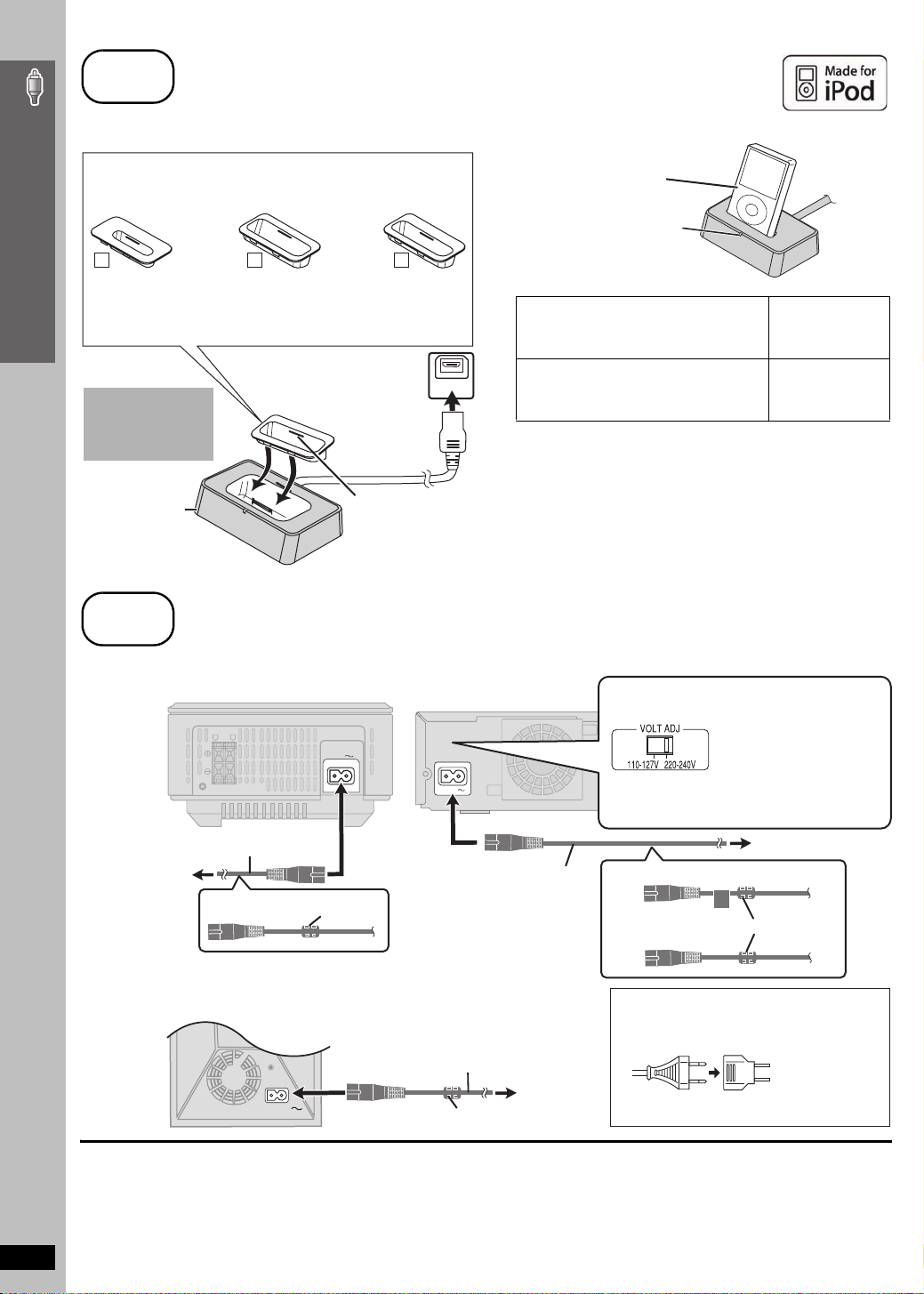
5
iPod connection
Proceed to step 6 if you are not going to enjoy iPod with the main unit.
For SC-PT953, use an optional SH-PD10 Universal Dock for iPod.
Dock adapter for
iPod nano 2nd
generation (aluminum)
(2GB, 4GB, 8GB)
Simple Setup
11
The mark
adapter.
≥ For other types of iPod, use the dock adapter sold separately.
Do not connect
or disconnect the
dock while the
main unit is on.
Universal Dock
for iPod
Dock adapter for
iPod 5th generation
(video) (60GB, 80GB)
10
[11], [10] or [9] is shown on the back of each dock
Or visit the official Apple website for compatible adapters.
Connect the dock to the
back of the main unit.
Dock adapter for
iPod 5th generation
(video) (30GB)
When removing, use
your fingernail or a flat
object to lift upwards.
∫ Charging the iPod
iPod (not included)
≥ Connect the iPod firmly.
The indicator lights up when
the iPod is inserted, and
9
OPTION V .1
charging starts.
Charging time
iPod nano 2nd generation (aluminum)
iPod 5th generation (video)
iPod nano 1st generation
iPod 4th generation (color display)
iPod 4th generation
iPod mini
Until iPod is fully
charged
5 hours (fixed)
[Note]
≥ AC cord must be connected with the main unit.
≥ “OPTION ¢” will be shown on the main unit’s display during iPod
charging in main unit standby mode. It will go off when charging is
finished.
For the above models under “fixed 5-hour charging”, “OPTION ¢”
continues to be displayed throughout this duration, even when your
iPod is fully charged. You can turn off this display by removing the
iPod from the dock.
≥Compatibility depends on the software version of your iPod.
iPod connection / AC cord connections
step
6
AC cord connections
Wireless system
LR
I/D SET
AC power supply cord (included)
To household AC
outlet
[PT1050]
Wireless subwoofer
[PT1050]
AC IN
AC IN
Ferri te core
Main unit
AC IN
AC power supply cord
(included)
AC power supply cord (included)
To household
Ferrite core
AC outlet
[PT950] [For\areas\except\U.S.A.[and\Canada]
Before connecting the
AC power supply cord
Set the voltage.
Use a flat-head screwdriver to
move the voltage selector to
the appropriate position for the
AV OUT
area in which this system is
used.
To household AC outlet
[PT950] [For\areas\except\U.S.A.\and\Canada]
[PT1050]
[PT950] [For\areas\except\U.S.A.\and\Canada]
≥ If the power plug does not fit your AC outlet
Use the power plug adaptor (included).
If it still does not fit, contact an electrical parts
distributor for assistance.
Ferr ite core
DIGITAL
PUSH PUSH
TRANSCEIVER
10
Conserving power
The main unit and the wireless equipment consume a small amount of
power when they are turned off (\U.S.A.\and\Canada]
wireless system: approx. 0.2 W, wireless subwoofer
\Others] main unit: approx. 0.9 W, wireless system: approx. 0.3 W).
RQTX0064
To save power when they are not to be used for a long time, unplug them
from the household AC outlet.
You will need to reset some memory items after plugging in the main unit.
main unit: approx.
[PT1050]:
approx. 0.3 W
0.5 W
[Note]
The included AC power supply cords are for use with the main unit and
,
wireless equipment only. Do not use them with other equipment. Also,
,
do not use cords for other equipment with the main unit or wireless
system.
∫ [PT1050] Before using your wireless subwoofer
Perform the pairing procedure below to use your wireless subwoofer.
Preparation
≥Ensure all connections are completed.
≥Turn on the main unit and reduce the volume.
1 Turn on your wireless subwoofer.
2 While pressing [5/9] on the main unit, press the numbered button [3] on the remote control until “P” lights in the main unit’s display.
3 While “P” is displayed, press [I/D SET].
I/D SET
Wireless subwoofer
4 While pressing [5/9] on the main unit, press the numbered button [3] on the remote control.
≥“ [WS] ” lights on the main unit’s display.
5 Turn the wireless subwoofer off and on again.
≥Make sure its indicator lights up green.
Use a pointed object.
I/D SET
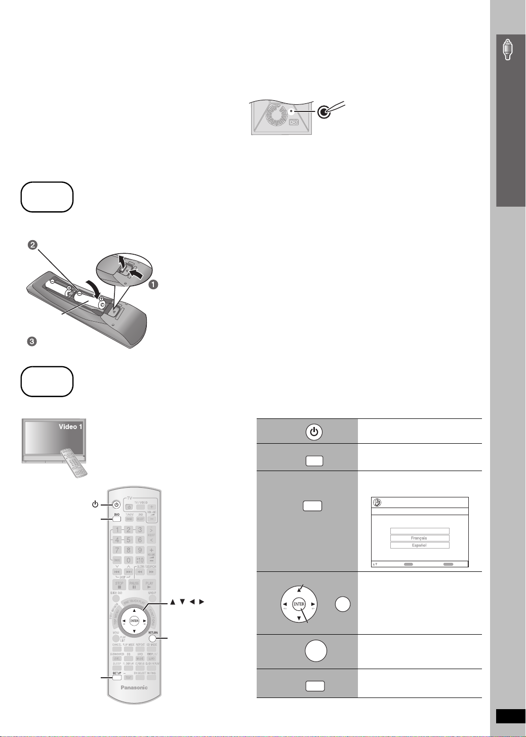
step
7
Preparing the remote control
∫ Batteries
Insert so the poles (i and j) match those in the remote control.
Press in and lift up.
R6/LR6, AA
Replace the cover.
≥ Do not use rechargeable type batteries.
Do not:
≥ mix old and new batteries.
≥ use different types at the same time.
≥ heat or expose to flame.
≥ take apart or short circuit.
≥ attempt to recharge alkaline or manganese batteries.
≥ use batteries if the covering has been peeled off.
Mishandling of batteries can cause electrolyte leakage which can
severely damage the remote control.
Remove the batteries if the remote control is not going to be used for a
long period of time. Store in a cool, dark place.
∫ Use
Aim at the remote control signal sensor (➜ page 13), avoiding
obstacles, at a maximum range of 7 m (23 feet) directly in front of
the unit.
Simple Setup
step
8
Performing QUICK SETUP
The QUICK SETUP screen assists you to make necessary settings.
To display the picture from the main unit,
turn on your television and change its video
input mode (e.g. VIDEO 1, AV 1, etc.).
≥To change your television’s video input mode,
refer to its operating instructions.
≥This remote control can perform some basic
television operations (➜ page 12).
1
2
3
DVD
4
, , ,
ENTER
SETUP
RETURN
AUTO
5
6
DVD
SETUP
Select
Register
ENTER
SETUP
Turn on the unit.
Select “DVD/CD”.
Show the QUICK SETUP
screen.
Setup
QUICK SETUP
Select the menu language.
English
ENTER
to select and press
Follow the messages
and make the settings.
RETURN
≥Menu Language
≥TV Type
≥TV Aspect
Press to finish QUICK
SETUP.
Press to exit.
RETURN
Preparing the remote control / Performing QUICK SETUP
to return
To change these settings later
Select “QUICK SETUP” in the “Others” menu (➜ page 27).
RQTX0064
11
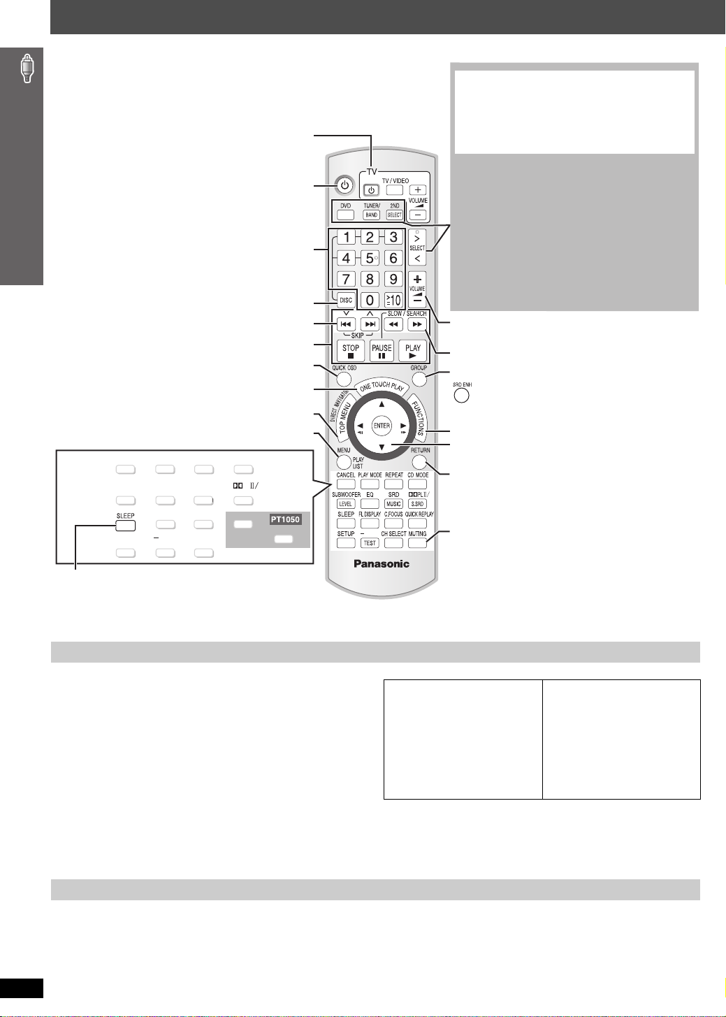
Control reference guide
See page references in parentheses.
Refer to “Operating the television” below.
Select disc’s title numbers etc./Enter numbers (17)
Select the disc or show disc information (18)
Select preset radio stations/channels (29, 31)
Basic operations for play (16, 17)
Display current playback condition (18)
Start up and play a disc automatically (17, 28)
Show a disc top menu (20) or program list (21)
Control reference guide
Show a disc menu (20) or play list (21)
CANCEL PLAY MODE REPEAT
(17) (19, 31) (18)(18)
SUBWOOFER
LEVEL
(32) (32)
SETUP
(25)
EQ
FL DISPLAY
(17)
AUTO
TEST
(33)
Turn the unit off automatically (Sleep timer)
≥ The maximum setting is 120-min (in 30-min steps).
≥ Press the button again to confirm the remaining time on
the unit’s display.
≥ To cancel, select “OFF” in the main unit’s display.
Television operations
Turn the main unit on/off (11)
CD MODE
SRD
MUSIC
S.SRD
(32)
(32)
(33)
(32)
QUICK REPLAY
(18)
C.FOCUS
CH SELECT
Select the source
[DVD]:
DVD/CD
[TUNER/BAND]:
[
N,O
(11)
FM/AM (29), XM
SELECT]:
DVD/CD, FM/AM, XM,
AUX
(34)
D-IN
(34) ([PT1050]
(30)
/ MUSIC P.
(34)
/
) / OPTION
(34)
The below function is available only when using the
optional Panasonic wireless sound system SH-FX85.
[2ND SELECT]:
MAIN SOURCE (follows the selected source for the
main room)#(FM#AM)
Change the source for the second room
§
#XM#OPTION#
Return to MAIN SOURCE
§
If the main room is in FM/AM mode, you can only
select the same mode for the FM/AM tuner of the
second room.
For details, refer to the operating instructions for the
optional Panasonic wireless sound system SH-FX85.
Adjust the volume of the main unit
Select radio stations/channels manually (29, 31)
Select a group of contents to play (17)
[PT1050]
Enhancing the surround sound effect (33)
Show on-screen menu (22)
Frame-by-frame/ Select or register menu items on the
television screen (17)/ Browse XM radio categories (31)
Return to previous screen (17)
PL
H.BASS
(33)
AUTO
Mute the sound
≥ “MUTING” flashes in the main unit’s display while
the function is on.
≥ To cancel, press the button again or adjust the
volume.
≥ Muting is canceled when you switch the unit to
standby.
Operating the television
Aim the remote control at the Panasonic television and press the
button.
[Í TV]: Turn the television on/off
[TV/VIDEO]: Change the television’s video input mode
[r, s]: Adjust the television volume
≥ This may not work properly with some models.
≥ To operate some other brands of televisions, change the remote control
code.
Aim the remote control at the television.
While pressing [Í TV], press the numbered buttons to enter the
4-digit television code.
If the code is correct, the television turns on or off. If it does not, try
entering another code.
]Note]
Reenter the codes after you change the batteries.
Avoiding interference with other Panasonic equipment
Other Panasonic audio/video equipment may start functioning when you
operate the unit using the supplied remote control.
You can operate this unit in another mode by setting the remote control
operating mode to “REMOTE 2”.
RQTX0064
12
Television code list
Panasonic: 0051, 0250
Fisher: 0154
GE: 0047
Gold Star: 0178, 0317, 0457
Hitachi: 0145
JVC: 0053
Magnavox: 0054
Mitsubishi: 0150
Philips: 0054
RCA: 0047
Samsung: 0060, 0587, 0702
Sanyo: 0154
Sharp: 0093, 0165
Sony: 0000
Sylvania: 0054
Thomson: 0047
Toshiba: 0156
Zenith: 0017
Quasar: 0051, 0250
The main unit and remote control must be set to the same mode.
1 Press and hold [5] on the main unit and [2] on the remote
control until the main unit's display shows "REMOTE 2".
2 Press and hold [ENTER] and [2] on the remote control for at least 2
seconds.
To change the mode back to “REMOTE 1”, repeat both steps above by
replacing [2] with [1].
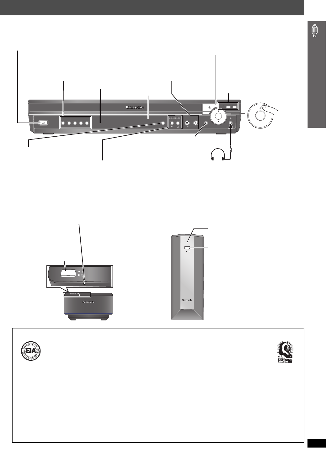
Standby/on switch [POWER Í/I]
Turn the main unit on/off.
Press to switch the unit from on to standby mode or
vice versa. In standby mode, the unit is still
consuming a small amount of power. (16)
5 DISC SELECTOR
Select a disc directly (16)
≥ A disc indicator lights if a disc is detected or a
tray is unchecked.
Remote control signal sensor
POWER
12345
5 DISC SELECTOR
SELECTOR (29)
DVD/CD#FM#AM#XM#
AUX #MUSIC P.#D-IN ([PT1050])#
OPTION#Return to DVD/CD
4, 5 / X TUNING W
Skip or slow-search play (16)/
Select the radio stations/channels (29, 31)
AUTO OPERATION ON/OFF indicator
The indicator lights red when the wireless system is turned on
and lights green when the wireless link is activated.
When the wireless link is inactive for a long time, it turns red.
Unit on/off button
[POWER C I, BÍ]
Use this button to turn
the unit on and off.
C I: This unit is on.
BÍ: This unit is off.
POWER
AUTO OPERATION ON/OFF
∫ /-TUNE MODE / —FM MODE
Stop playing (16)/
Select the tuning mode (29)
Adjust the FM reception condition (29)
1/MEMORY
Play discs (16)/ Memorize the receiving
radio stations/channels (29, 31)
Display
OPEN CLOSE
SELECTOR
TUNING
TUNE MODE FM MODE
MEMORY
MUSIC PORT
SETUP MIC
MUSIC PORT/SETUP MIC
Connect an external device (34)/
Connect the setup microphone (33)
Headphones (not included)
Headphone plug type: ‰3.5 mm (1/8z) stereo mini plug
≥ Reduce the volume before connecting.
≥ Audio is automatically switched to 2-channel stereo.
≥ To prevent hearing damage, avoid listening for
prolonged periods of time.
[PT1050]
POWER
AUTO OPERATION
ON/OFF
< OPEN/CLOSE
Open/Close the disc drawer (16)
DISC EXCHANGE
Open the disc drawer to exchange
the disc in the play position (16)
DISC SKIP
Skip to the next disc tray (16)
SKIP
DISC
EXCHANGE
VOLUME
VOLUME
Adjust the volume of
the main unit.
AUTO OPERATION ON/OFF indicator
The indicator lights red when the wireless
system is turned on and lights green when
the wireless link is activated.
When the wireless link is inactive for a long
time, it turns red.
Unit on/off button
[POWER BÍ, C I]
Use this button to turn
the unit on and off.
BÍ: This unit is off.
C I: This unit is on.
Control reference guide
EST. 1924
Selecting fine audio equipment such as the unit
you’ve just purchased is only the start of your
musical enjoyment. Now it’s time to consider
how you can maximize the fun and excitement
your equipment offers. This manufacturer and
the Electronic Industries Association’s
Consumer Electronics Group want you to get
the most out of your equipment by playing it at a
safe level. One that lets the sound come
through loud and clear without annoying blaring
or distortion—and, most importantly, without
affecting your sensitive hearing.
Listening caution
We recommend that you avoid prolonged
exposure to excessive noise.
Sound can be deceiving. Over time your
hearing “comfort level” adapts to higher
volumes of sound. So what sounds “normal”
can actually be loud and harmful to your
hearing.
Guard against this by setting your equipment at
a safe level BEFORE your hearing adapts.
To establish a safe level:
≥ Start your volume control at a low setting.
≥ Slowly increase the sound until you can hear
it comfortably and clearly, and without
distortion.
Once you have established a comfortable
sound level:
≥ Leave it there.
Taking a minute to do this now will help to
prevent hearing damage or loss in the future.
After all, we want you listening for a lifetime.
RQTX0064
13
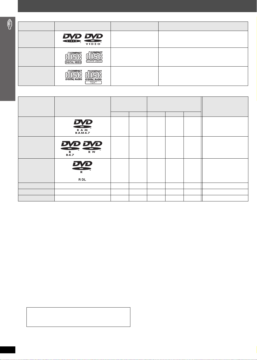
Discs that can be played
Commercial discs
Disc Logo
DVD- Video [DVD-V] High quality movie and music discs
Indicated in these
instructions by
Remarks
Video CD [VCD]
CD
[CD] Music discs
Music discs with video
Including SVCD (Conforming to IEC62107)
Recorded discs (±: Playable, k: Not playable)
Disc Logo
DVD-RAM
DVD-R/RW
Recorded on a
DVD video
recorder, etc.
[DVD-VR]§2[DVD-V]
± — k±±
±±k±±
Recorded on a personal
computer, etc.
§4
[WMA] [MP3] [JPEG]
Finalizing
Not necessary
Necessary
Discs that can be played
DVD-R DL
iR/iRW
iR
DL
CD-R/RW
≥ It may not be possible to play all the above-mentioned discs in some cases due to the type of disc, the condition of the recording, the recording
method, or how the files were created (➜ page 15, Tips for making data discs).
§1
This unit can play CD-R/RW recorded with CD-DA or Video CD format.
[WMA] [MP3] [JPEG] This unit also plays HighMAT discs.
§2
Discs recorded on DVD video recorders or DVD video cameras, etc. using Version 1.1 of the Video Recording Format (a unified video recording
standard).
§3
Discs recorded on DVD video recorders or DVD video cameras using Version 1.2 of the Video Recording Format (a unified video recording
standard).
§4
Discs recorded on DVD video recorders or DVD video cameras using DVD-Video Format.
§5
Recorded using a format different from DVD-Video Format, therefore some functions cannot be used.
§6
A process that allows play on compatible equipment. To play a disc that is indicated as “Necessary”, the disc must first be finalized on the device it
was recorded on.
§7
Closing the session will also work.
§1
— k (±)
— k (±)
———±±±
±
§3
±kkk
§5
kkk
§5
kkk
Necessary
Necessary
Necessary
Necessary
§6
§7
∫ Discs that cannot be played
DVD-RW version 1.0, DVD-Audio, DVD-ROM, CD-ROM, CDV,
CD-G, SACD, DivX Video Discs and Photo CD, DVD-RAM that
cannot be removed from their cartridge, 2.6-GB and 5.2-GB
DVD-RAM, and “Chaoji VCD” available on the market including
CVD, DVCD and SVCD that do not conform to IEC62107.
Note about using a DualDisc
The digital audio content side of a DualDisc does not meet the
technical specifications of the Compact Disc Digital Audio
(CD-DA) format so playback may not be possible.
RQTX0064
14
∫ Disc handling precautions
≥Do not attach labels or stickers to discs. This may cause disc
warping, rendering it unusable.
≥Do not write on the label side with a ball-point pen or other writing
instrument.
≥Do not use record cleaning sprays, benzine, thinner, liquids which
prevent static electricity, or any other solvent.
≥Do not use scratch-proof protectors or covers.
≥Do not use the following discs:
– Discs with exposed adhesive from removed stickers or labels
(rented discs, etc.).
– Discs that are badly warped or cracked.
– Irregularly shaped discs, such as heart shapes.
 Loading...