

Panasonic SC-HT995, SC-HT995W User Manual
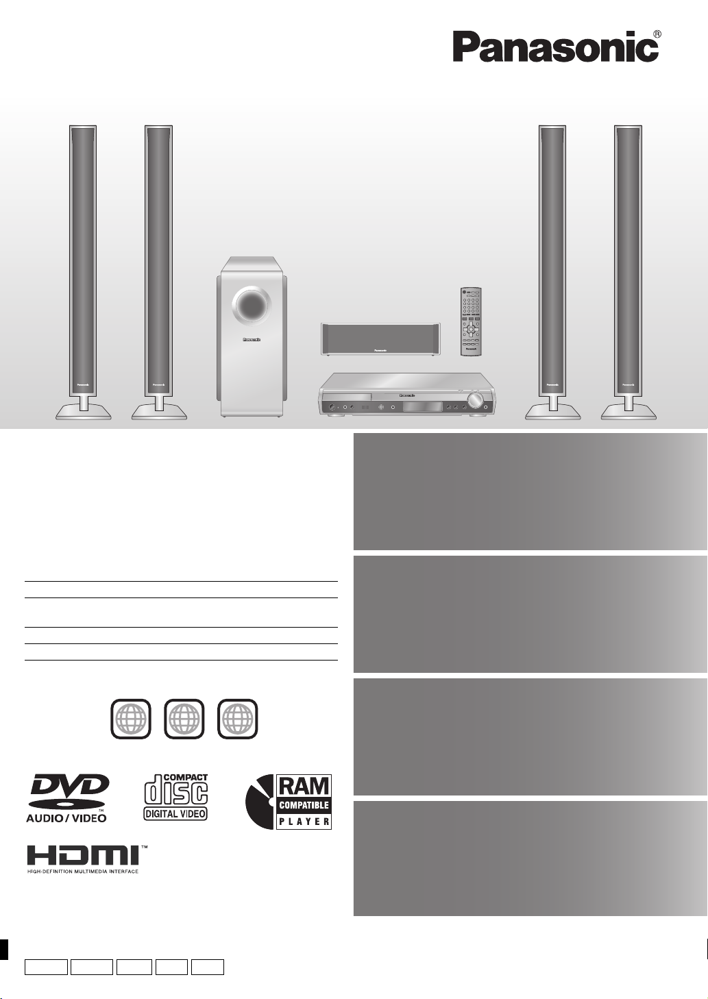
The illustration shows SC-HT995.
Operating Instructions
DVD Home Theater Sound System
Model No.
Region number
The player plays DVD-Video marked with labels containing the region
number or “ALL”.
The Middle East, South Africa, Saudi Arabia and
Kuwait
Southeast Asia and Thailand 3
Australia and N.Z. 4
Example:
[Southeast\Asia\and[Thailand[
SC-HT995/SC-HT995W
Region Number
2
2
3 ALL
3
5
Wireless system and
digital transceiver
Wireless surround speaker
connection. (
§
For SC-HT995W only.)
§
page
11
High-quality
picture
page
13
HDMI capability, Advanced
progressive scan and more.
Compatible with a variety
of media formats
page
17
DVD-RAM, DVD-Audio,
DVD-Video, DivX and more.
High-performance
Before connecting, operating or adjusting this product,
please read the instructions completely.
Please keep this manual for future reference.
GCS GC GSGCT
GN
sound effects
Sound quality enhancement,
Bass enhancement and more.
page
34
RQT8766-2L
Dear customer
∏
∏
∏
∏
∏
∏
∏
Thank you for purchasing this product. For optimum performance and safety, please read these instructions carefully.
≥ These operating instructions are applicable to models SC-HT995 and SC-HT995W for a variety of regions.
≥ Unless otherwise indicated, illustrations in these operating instructions are of SC-HT995.
≥ Operations in these instructions are described mainly with the remote control, but you can perform the operations on the main unit if
the controls are the same.
[HT995]: indicates features applicable to SC-HT995 only.
[HT995W]: SC-HT995W only
System SC-HT995 SC-HT995W
Main unit SA-HT995 SA-HT995
Front speakers SB-FS995 SB-FS990
Center speaker SB-PC995 SB-PC895
Surround speakers
SB-FS996 SB-FS540
Subwoofer SB-W995 SB-W895
Wireless system ` SE-FX61
Digital transceiver ` SH-FX80T
Accessories
Accessories
Please check and identify the supplied accessories.
1 Remote control
(N2QAYZ000003)
∏ [HT995] 4 Stands
2kstands with short cable
2kstands with long cable
∏ [HT995W] 4 Stands
2kstands with short cable
2kstands with long cable
∏ [HT995]
AC mains lead
[Southeast[Asia,
[
the[Middle[East,[South[Africa,[
[Thailand,[
[Saudi[Arabia[and[Kuwait[
2 Remote control batteries
1 AM loop antenna
∏ [HT995] 4 Bases
∏ [HT995W] 4 Bases
[Saudi[Arabia[and[Kuwait[
∏ [HT995] 12 Screws
1 FM indoor antenna
∏ [HT995W] 16 Screws
[HT995W]
2 AC mains leads
1 Video cable
∏ [HT995] 4 Sliders
∏ [HT995W] 4 Cover plates
Speaker cables
[HT995]
2kshort cable
[HT995W]
1kshort cable
2 Sheets of speaker cable
stickers
CENTER
WOOFER
SUB
6
5
5
6
SUB
WOOFER
CENTER
SURROUND
SURROUND
Rch
Lch
3
4
4
3
Rch
SURROUND
SURROUND
FRONT
FRONT
Rch
Lch
2
1
1
2
Lch Lch
Rch
FRONT
FRONT
RQT8766
2
TABLE OF CONTENTS
Getting
Started
Playing
Discs
Accessories . . . . . . . . . . . . . . . . . . . . . . . . . . . . . 2
Caution for AC Mains Lead. . . . . . . . . . . . . . . . . 4
Safety precautions . . . . . . . . . . . . . . . . . . . . . . .5
About DivX VOD content . . . . . . . . . . . . . . . . . .5
Simple Setup
STEP 1
STEP 2
STEP 3
STEP 4
Basic play. . . . . . . . . . . . . . . . . . . . . . . . . . . . . . 18
Using the main unit . . . . . . . . . . . . . . . . . . . . . . . . . . . 18
Using the remote control . . . . . . . . . . . . . . . . . . . . . . 19
Convenient functions . . . . . . . . . . . . . . . . . . . . 20
Displaying current playback condition. . . . . . . . . . . . . 20
All group, Program and Random play . . . . . . . . . . . . . 20
Playing data discs using navigation menus
Playing data discs. . . . . . . . . . . . . . . . . . . . . . . . . . . . 21
Selecting a track using CD text. . . . . . . . . . . . . . . . . . 22
Playing HighMAT
Playing RAM and DVD-R/-RW (DVD-VR) discs. . . . . 22
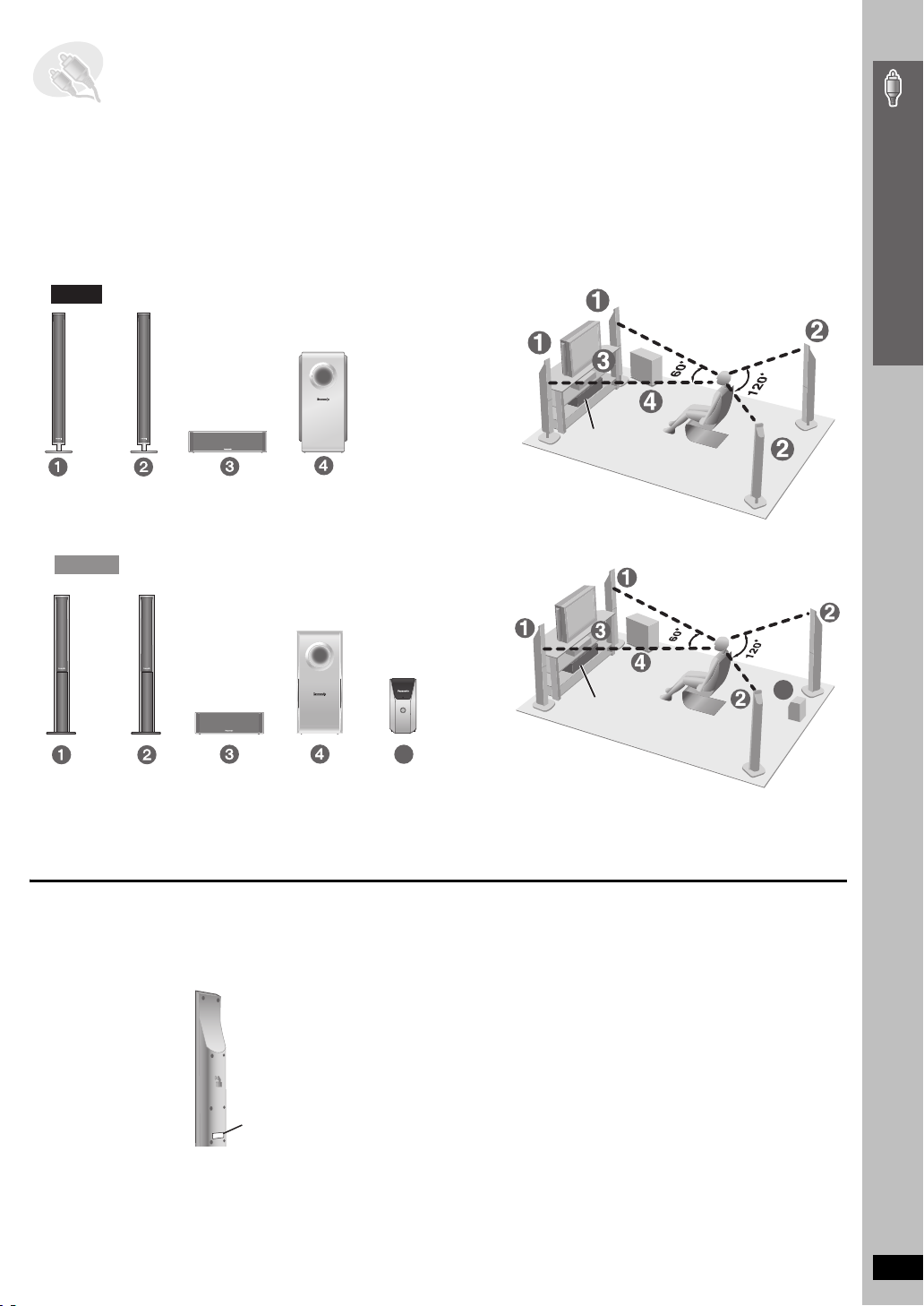
Assembling the front and surround speakers
Speaker installation options . . . . . . . . . . . . . 8
Positioning the speakers . . . . . . . . .9
Speaker connections
[HT995W] Connecting the surround speaker
cables to the wireless system . . . . . . . . 11
Radio and digital transceiver
connections . . . . . . . . . . . . . . . . . 12
[HT995W] Connecting the
digital transceiver . . . . . . . . . . . . . . . . . . 12
TM
discs . . . . . . . . . . . . . . . . . . . . . . 22
. . . . . . . . . . . . 11
. . . 6
. . . 21
STEP 5
STEP 6
STEP 7
STEP 8
Control reference guide . . . . . . . . . . . . . . . . . 16
Discs that can be played. . . . . . . . . . . . . . . . . 17
Disc caution . . . . . . . . . . . . . . . . . . . . . . . . . . . 17
Maintenance. . . . . . . . . . . . . . . . . . . . . . . . . . . 17
Using on-screen menus . . . . . . . . . . . . . . . . . . 24
Main menu . . . . . . . . . . . . . . . . . . . . . . . . . . . . . . . . . 24
Other Settings . . . . . . . . . . . . . . . . . . . . . . . . . . . . . . 25
Changing the player settings . . . . . . . . . . . . . . 28
Changing the delay time of the speakers. . . . . . . . . . 31
Audio and video connections. . . . 13
Television with an HDMI terminal . . . . . . . .13
Basic audio connection . . . . . . . . . . . . . . .13
Basic video connection . . . . . . . . . . . . . . .13
AC mains lead connections . . . . . 14
Preparing the remote control . . . . 15
Performing QUICK SETUP . . . . . . 15
Other
Operations
Reference
Using the radio . . . . . . . . . . . . . . . . . . . . . . . . . 32
Presetting stations automatically . . . . . . . . . . . . . . . . 32
Selecting the preset channels . . . . . . . . . . . . . . . . . . 32
Manual tuning . . . . . . . . . . . . . . . . . . . . . . . . . . . . . . . 32
Using an outdoor antenna (optional) . . . . . . . . . . . . . 33
Using sound effects . . . . . . . . . . . . . . . . . . . . .34
Changing the sound quality: Sound Field Control . . . 34
Enhancing the sound from the center speaker:
Center Focus . . . . . . . . . . . . . . . . . . . . . . . . . . . . . . 34
Enhancing the stereo sound: Dolby Pro Logic II . . . . 34
Adjusting the amount of bass: Subwoofer level . . . . . 34
Enhancing the bass sound: H.BASS . . . . . . . . . . . . . 35
Enhancing the surround sound effect:
Surround Enhancer . . . . . . . . . . . . . . . . . . . . . . . . . 35
Adjusting the volume of each speaker:
Speaker level adjustments. . . . . . . . . . . . . . . . . . . . 35
Troubleshooting guide . . . . . . . . . . . . . . . . . . .40
Glossary . . . . . . . . . . . . . . . . . . . . . . . . . . . . . . . 43
Using other useful functions . . . . . . . . . . . . . .36
Setting the sleep timer . . . . . . . . . . . . . . . . . . . . . . . . 36
Muting the sound . . . . . . . . . . . . . . . . . . . . . . . . . . . . 36
Using headphones . . . . . . . . . . . . . . . . . . . . . . . . . . . 36
Using the Music Port . . . . . . . . . . . . . . . . . . . . . . . . . 36
[HT995] Enjoying Karaoke . . . . . . . . . . . . . . . . . . . . . . 37
Operating other equipment . . . . . . . . . . . . . . . 38
Operating the television . . . . . . . . . . . . . . . . . . . . . . . 38
[HT995W] Operating the cable TV box, digital
broadcasting or satellite receiver . . . . . . . . . . . . . . 38
Operating both the television and the home
theater system: Control with HDMI
(HDAVI Control
One Touch Play . . . . . . . . . . . . . . . . . . . . . . . . . . . . . 39
Automatic input switching. . . . . . . . . . . . . . . . . . . . . . 39
Theater speaker . . . . . . . . . . . . . . . . . . . . . . . . . . . . . 39
Power off link . . . . . . . . . . . . . . . . . . . . . . . . . . . . . . . 39
Specifications . . . . . . . . . . . . . . . . . . . . . . . . . .44
TM
) . . . . . . . . . . . . . . . . . . . . . .39
RQT8766
3
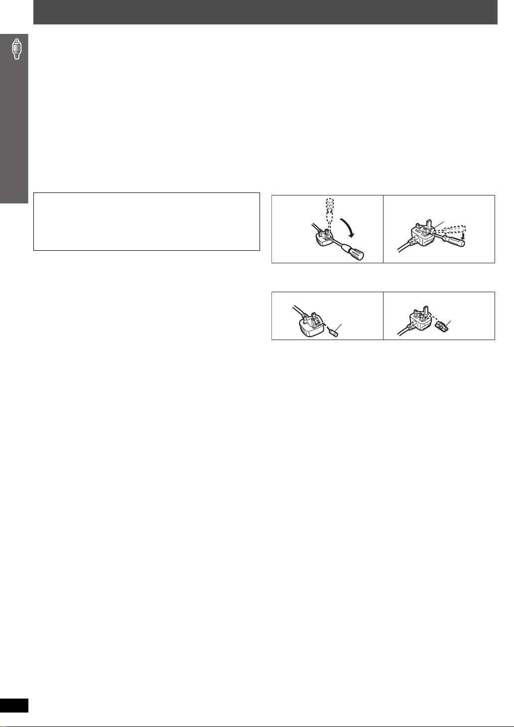
Caution for AC Mains Lead
(For Saudi Arabia and Kuwait)
(“GS” area code model only)
For your safety, please read the following text carefully.
This appliance is supplied with a moulded three pin mains plug for your
safety and convenience.
A 5-ampere fuse is fitted in this plug.
Should the fuse need to be replaced please ensure that the replacement
fuse has a rating of 5-ampere and that it is approved by ASTA or BSI to
BS1362.
Check for the ASTA mark Ï or the BSI mark Ì on the body of the fuse.
If the plug contains a removable fuse cover you must ensure that it is
refitted when the fuse is replaced.
If you lose the fuse cover the plug must not be used until a replacement
cover is obtained.
A replacement fuse cover can be purchased from your local dealer.
CAUTION!
IF THE FITTED MOULDED PLUG IS UNSUITABLE FOR THE
SOCKET OUTLET IN YOUR HOME THEN THE FUSE SHOULD BE
REMOVED AND THE PLUG CUT OFF AND DISPOSED OF SAFELY.
THERE IS A DANGER OF SEVERE ELECTRICAL SHOCK IF THE
CUT OFF PLUG IS INSERTED INTO ANY 13-AMPERE SOCKET.
If a new plug is to be fitted please observe the wiring code as stated
below.
If in any doubt please consult a qualified electrician.
IMPORTANT
The wires in this mains lead are coloured in accordance with the following
Caution for AC Mains Lead
code:
Blue: Neutral, Brown: Live.
As these colours may not correspond with the coloured markings
identifying the terminals in your plug, proceed as follows:
The wire which is coloured Blue must be connected to the terminal which
is marked with the letter N or coloured Black or Blue.
The wire which is coloured Brown must be connected to the terminal
which is marked with the letter L or coloured Brown or Red.
WARNING: DO NOT CONNECT EITHER WIRE TO THE
EARTH TERMINAL WHICH IS MARKED WITH THE LETTER
E, BY THE EARTH SYMBOL Ó OR COLOURED GREEN OR
GREEN/YELLOW.
THIS PLUG IS NOT WATERPROOF—KEEP DRY.
Before use
Remove the connector cover.
How to replace the fuse
The location of the fuse differ according to the type of AC mains plug
(figures A and B). Confirm the AC mains plug fitted and follow the
instructions below.
Illustrations may differ from actual AC mains plug.
1. Open the fuse cover with a screwdriver.
Figure A Figure B
Fuse cover
2. Replace the fuse and close or attach the fuse cover.
Figure A Figure B
Fuse
(5 ampere)
Fuse
(5 ampere)
RQT8766
4
Safety precautions
Placement
Set the unit up on an even surface away from direct sunlight, high
temperatures, high humidity, and excessive vibration. These conditions
can damage the cabinet and other components, thereby shortening the
unit’s service life.
Do not place heavy items on the unit.
Volt ag e
Do not use high voltage power sources. This can overload the unit and
cause a fire.
Do not use a DC power source. Check the source carefully when setting
the unit up on a ship or other places where DC is used.
AC mains lead protection
Ensure the AC mains lead is connected correctly and not damaged. Poor
connection and lead damage can cause fire or electric shock. Do not pull,
bend, or place heavy items on the lead.
Grasp the plug firmly when unplugging the lead. Pulling the AC mains
Foreign matter
Do not let metal objects fall inside the unit. This can cause electric shock
or malfunction.
Do not let liquids get into the unit. This can cause electric shock or
malfunction. If this occurs, immediately disconnect the unit from the power
supply and contact your dealer.
Do not spray insecticides onto or into the unit. They contain flammable
gases which can ignite if sprayed into the unit.
Service
Do not attempt to repair this unit by yourself. If sound is interrupted,
indicators fail to light, smoke appears, or any other problem that is not
covered in these instructions occurs, disconnect the AC mains lead and
contact your dealer or an authorized service center. Electric shock or
damage to the unit can occur if the unit is repaired, disassembled or
reconstructed by unqualified persons.
Extend operating life by disconnecting the unit from the power source if it
is not to be used for a long time.
lead can cause electric shock.
Do not handle the plug with wet hands. This can cause electric shock.
About DivX VOD content
DivX Video-on-Demand (VOD) content is encrypted for copyright protection. In order to play DivX VOD content on this unit, you first need to register the
unit.
Follow the online instructions for purchasing DivX VOD content to enter the unit’s registration code and register the unit. For more information about
DivX VOD, visit www.divx.com/vod.
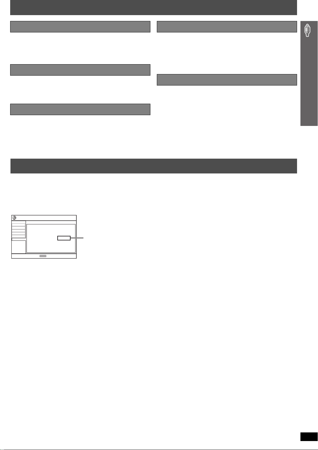
Display the unit’s registration code
(➜ page 30, “DivX Registration” in “Others” tab)
Disc
Video
Audio
HDMI
Display
Others
Setup
DivX Registration
DivX Video-on-Demand
Your registration code is : XXXXXXXX
To learn more visit www.divx.com/vod
ENTER
to continuePress
8 alphanumeric characters
≥ We recommend that you make a note of this code for future reference.
≥ After playing DivX VOD content for the first time, another registration
code is then displayed in “DivX Registration”. Do not use this
registration code to purchase DivX VOD content. If you use this code to
purchase DivX VOD content, and then play the content on this unit, you
will no longer be able to play any content that you purchased using the
previous code.
≥ If you purchase DivX VOD content using a registration code different
from this unit’s code, you will not be able to play this content.
(“Authorization Error” is displayed.)
Regarding DivX content that can only be played a set
number of times
Some DivX VOD content can only be played a set number of times. When
you play this content, the remaining number of plays is displayed. You
cannot play this content when the number of remaining plays is zero.
(“Rented Movie Expired” or “Rental Expired” is displayed.)
When playing this content
≥ The number of remaining plays is reduced by one if
– you press [Í] or press and hold [—SETUP].
– you press [∫ STOP]. (Press [; PAUSE] to pause play.)
– you press [:, 9 SKIP] or [6, 5 SLOW/SEARCH] etc. and
arrive at another content or the start of the content being played.
≥ Resume (➜ page 19, Stop) and Marker (➜ page 25, Play Menu)
functions do not work.
Safety precautions / About DivX VOD content
RQT8766
5
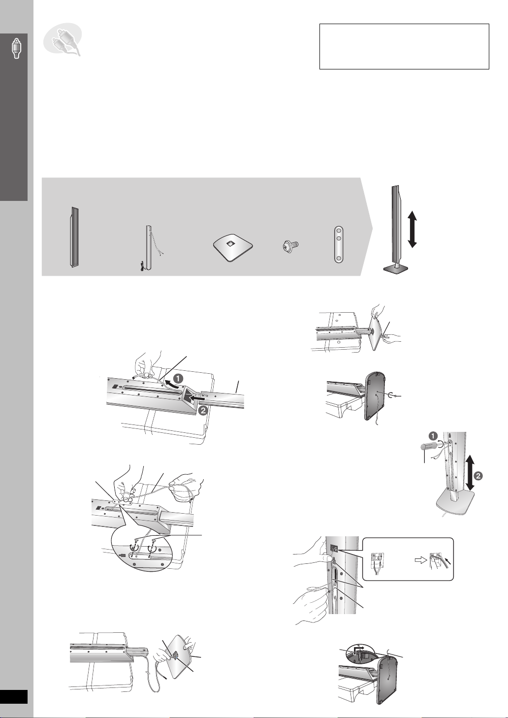
STEP1 Assembling the front and
surround speakers
Preparation
≥ To prevent damage or scratches, lay down a soft cloth and perform assembly on it.
≥ For assembly, use a Phillips-head screwdriver.
≥ Make sure you have all the indicated components before starting assembly, setup, and connection.
≥ There is no difference between the right and left speakers and stands.
Simple Setup
≥ For optional wall mount, refer to page 8.
[HT995]
[Note]
≥ The front and surround speakers are different.
– Check the label on the rear of speaker before attaching the stand (➜ page 9).
– The stand with shorter cable is for the front speaker.
2 Front speakers and
2 Surround speakers
≥ 2kstands with short cable:
For front speakers
≥ 2kstands with long cable:
For surround speakers
4 Bases4 Stands
12 Screws
The supplied stands are specially designed for
attachment to Panasonic SB-FS995 front
speakers, SB-FS996 surround speakers or
SB-FS990 front speakers, SB-FS540 surround
speakers. Use only as indicated in this setup.
4 Sliders
The speaker height
can be adjusted.
Min: 110 cm
Max: 135 cm
1 Attach the speaker to the stand.
Place the polyfoam under neath the speaker for stability while
attaching the speaker to the stand.
1 Feed the speaker cable (the shorter part) into the bottom
of the speaker and through the slot at the rear.
2 While pulling the speaker cable up through the slot, slide
the speaker stand into the bottom of the speaker.
Speaker
Assembling the front and surround speakers
3 Thread the cable through the middle hole of the slider and
fasten the slider with the two screws.
Slider
2 Attach the stand to the base.
1 Thread the speaker cable through the base.
For quicker threading, loosely fold the cable in half (do not
crease), pass the folded portion through the hole, and then pull
the rest of the cable through the base.
RQT8766
6
Cable
Cable
Base
Cable
Polyfo am
Screws
Tighten securely.
Rounded side
Large hole
Stand
2 Insert the stand into the base while g ently pulling on the
end of the cable.
Cable
3 Secure the stand to the base.
Screw
Tighten securely.
4 Adjust the speaker height.
1 Loosen the screws until
the speaker can slide up
and down the stand.
2 Raise the speaker to the
desired height, and then
re-tighten the screws.
Phillips-head
screwdriver
5 Connect the speaker cable.
Insert the wire fully.
_: White
`: Blue
Push!
Press the speaker cable into the groove.
Push excess cable back through the
slider holder.
6 Secure the speaker cable to the base.
Slide the cable
into the groove.
Cable
[HT995W]
[Note]
≥ The front and surround speakers are different.
– Check the label on the rear of speaker before attaching the stand (➜ page 9).
– The stand with shor ter cable is for the front speaker.
2 Front speakers and
2 Surround speakers
(with cover plate)
4 Stands
≥ 2kstands with short cable:
For front speakers
≥ 2kstands with long cable:
For surround speakers
4 Bases
16 Screws
Simple Setup
1 Attach the stand to the base.
1 Thread the speaker cable through the base .
For quicker threading, loosely fold the cable in half (do not
crease), pass the folded portion through the hole, and then pull
the rest of the cable through the base.
Cable
Base
2 Attach the stand to the base while gently pulling on the
end of the speaker cable.
Stand
Base
Cable
Pull gently.
2 Secure the stand to the base.
Screw
Tighten securely.
Stand
Base
Slide the speaker
cable into the groove.
Screws
Tighten securely.
3 Attach the speaker to the stand.
1 Pull out the end of
the speaker cable
and position it
between the ridges.
2 Attach the speaker to the stand.
Speaker
Stand
Ridges
Stand
Cover plate
Remove before attaching
the speaker and keep for
wall-mount use (➜ page 8).
4 Secure the speaker to the stand.
Speaker
Screw
Tighten securely.
Stand
Ensure the speaker cable is
centered in the groove.
5 Connect the speaker cable.
_: White
`: Blue
Press the speaker cable
into the groove.
Cable
Assembling the front and surround speakers
Insert the wire fully.
Push!
∫ Preventing the speakers from falling
≥ You will need to obtain the appropriate screw eyes to match the
walls or pillars to which they are going to be fastened.
≥ Consult a qualified housing contractor concerning the
appropriate procedure when attaching to a concrete wall or a
surface that may not have strong enough support. Improper
attachment may result in damage to the wall or speakers.
e.g. [HT995]
String (not included)
Thread from the wall to the speaker and tie tightly.
Rear of the speaker
Screw eye
(not included)
Wall
Approx.
150 mm
RQT8766
7
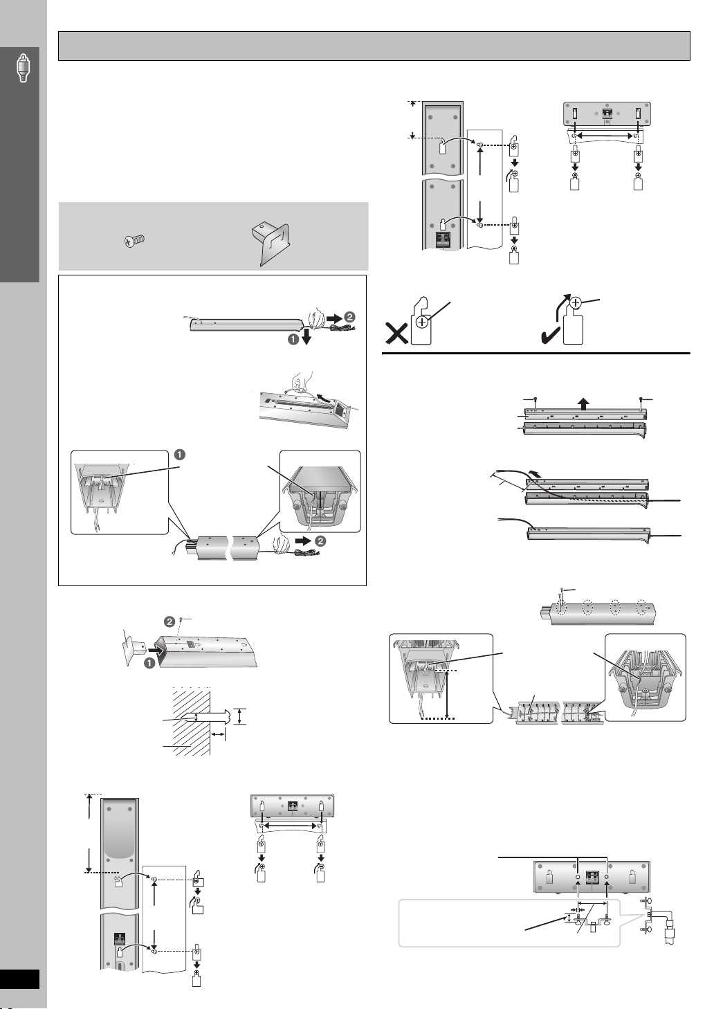
Speaker installation options
∫ Attaching to a wall
You can attach all of the speakers (except subwoofer) to a wall.
≥ The wall or pillar on which the speakers are to be attached
should be capable of supporting over 15 kg ([HT995W] 10 kg) per
screw. Consult a qualified building contractor when attaching the
speakers to a wall. Improper attachment may result in damage to
the wall and speakers.
Simple Setup
≥ When mounting the front speakers or surround speakers to a
wall, we recommend using a string (not included) to prevent it
from falling.
[HT995W] 4 Screws
Preparation for front and surround speakers
[HT995]
1 Pull down the longer
part of the cable to
release the cable from
the groove inside the
stand, and then pull the speaker cable out from the stand.
Feed the cable into the bottom of the
2
speaker and through the slot at the rear.
3 Connect the cable (➜ page 6).
[HT995W]
1 Remove the speaker cable from the stand.
[HT995W] 4 Cover plates
Release the cable
from the groove.
Front and surround speaker [HT995W]
106 mm
340 mm
e.g.
Reattaching the speaker cable to the stand
[HT995]
1 Remove the two screws from the stand, and remove the metal cover.
2 Pull the cable out about 40 cm from the hole in the metal cover, and
insert the plastic cover.
In this position, the
speaker will likely
fall if moved to the
left or right.
Screw
Metal cover
Plastic cover
Approx. 40 cm
Center speaker [HT995W]
200 mm
Move the speaker
so that the screw is
in this position.
Screw
Assembling the front and surround speakers
2 Connect the cable (➜ page 7).
1 [HT995W] Attach the cover plate to the front speaker or surround
2 Drive a screw (not included) into the wall.
3 Fit the speaker securely onto the screw(s) with the hole(s).
Front and surround speaker [HT995]
255 mm
RQT8766
speaker.
Cover plate
‰4.0 mm
Wall or pillar
Screw
Tighten securely.
‰7.5 to 9.5 mm
5.0 to 7.0 mm
Center speaker [HT995]
190 mm
320 mm
8
3 Insert the metal cover
so it does not disturb
the cable and close
tightly with the two screws.
[HT995W]
1 Remove the eight screws
from the stand, and remove
the speaker net.
2 Position the cable.
Press the cable into
the groove.
Approx.
15 cm
3 Attach the speaker net with the screws.
Cable
Screw
∫ Fitting speaker stands (not included)
(For center speaker)
Ensure the stands meet these conditions before purchasing them.
Note the diameter and length of the screws and the distance
between screws as shown in the diagram.
≥ The stands must be able to suppor t over 10 kg.
≥
The stands must be stable even if the speakers are in a high position.
e.g. Center speaker [HT995]
Metal screw holes
For attaching to
speaker stands
5 mm, pitch 0.8 mm
Plate thickness plus
7 mm to 10 mm
60 mm
Speaker stand
(not included)
STEP2 Positioning the speakers
How you set up your speakers can affect the bass and the sound field. Note the following points:
≥ Place speakers on flat secure bases.
≥ Placing speakers too close to floors, walls, and corners can result in excessive bass. Cover walls and windows with thick curtains.
≥ Left and right speakers are interchangeable, but front and surround speakers are not.
≥ Place the front, center, and surround speakers at approximately the same distance from the seating position.
The angles in the diagram are approximate.
HT995
Setup example
Main unit
Simple Setup
FRONT
(L, R)
SURROUND
(L, R)
CENTER
SUBWOOFER
HT995W
FRONT
(L, R)
SURROUND
(L, R)
CENTER
SUBWOOFER
WIRELESS
SYSTEM
[Note]
Do not use a front speaker as a surround speaker or vice versa.
Verify the type of speaker with the label on the rear of the front
speaker.
e.g. [HT995]
Setup example
5
Main unit
(with digital transceiver)
Positioning the speakers
5
Speaker label
(Continued on next page)
RQT8766
9
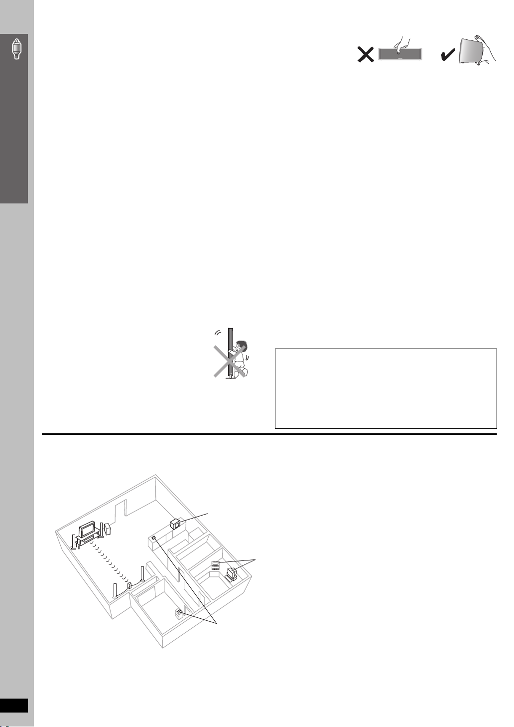
≥Use only supplied speakers
Using other speakers can damage the unit, and sound quality will be
negatively affected.
≥ Set the speakers up on an even surface to prevent them from falling.
Take proper precautions to prevent the speakers from falling if you
cannot set them up on an even surface.
Main unit
[Note]
≥ Keep your speakers at least 10 mm away from the system for proper
ventilation.
Simple Setup
≥ To allow for proper ventilation and to maintain good airflow around the
main unit, position it with at least 5 cm of space on all sides.
≥ Do not block the ventilation holes of the main unit.
Center speaker
≥ Vibration caused by the center speaker can disrupt the picture if it is
placed directly on the television. Put the center speaker on a rack or
shelf.
≥ To prevent the speakers from falling, do not place directly on top of the
television.
Wireless system
[HT995W]
≥
Place the wireless system within approximately 10 m from the main unit.
≥ Do not use the wireless system or the digital transceiver in a metal
cabinet or bookshelf.
Subwoofer
Place to the right or left of the television, on the floor or a sturdy shelf so
that it will not cause vibration. Leave about 30 cm from the television.
Caution
Positioning the speakers
≥ Do not stand on the base.
Be cautious when children are near.
e.g. [HT995] Front speaker
≥ Do not touch the netted
area of the speakers.
e.g. [HT995] Center speaker
Notes on speaker use
≥ You can damage your speakers and shorten their useful life if you play
sound at high levels over extended periods.
≥ Reduce the volume in the following cases to avoid damage:
– When playing distorted sound.
– When the speakers are reverberating due to a record player, a
microphone (
signals from an oscillator, test disc, or electronic instrument.
– When adjusting the sound quality.
– When turning the unit on or off.
[HT995]
only), noise from FM broadcasts, or continuous
If irregular coloring occurs on your television
The front and center speakers are designed to be used close to a
television, but the picture may be affected with some televisions and
setup combinations.
If this occurs, turn the television off for about 30 minutes.
The demagnetizing function of the television should correct the problem.
If it persists, move the speakers further away from the television.
Caution
≥ The main unit and supplied speakers are to be used only as
indicated in this setup. Failure to do so may lead to damage to
the amplifier and/or the speakers, and may result in the risk of
fire. Consult a qualified service person if damage has occurred
or if you experience a sudden change in performance.
≥ Do not attempt to attach these speakers to walls using
methods other than those described in this manual.
∫ [HT995W] Avoiding interference
To avoid possible interference, do not place the wireless system near any of the following devices.
The wireless system uses the same radio frequencies as other devices that may be present in your home.
e.g.
2.4GHz-band microwave oven
personal computer with
2.4GHz-band wireless LAN
2.4GHz-band cordless phone
10
The wireless system will automatically seek a clear channel if any of these other devices interfere with its communication. When this happens, the
wireless link indicator (“ [W] ”) flashes on the main unit, and there is a brief interruption in audio coming from the surround speakers.
This is the normal operation of the product working to assure the best possible performance of your Home Theater System.
If the interference persists, try moving the other devices to another location outside the range of the wireless system.
RQT8766
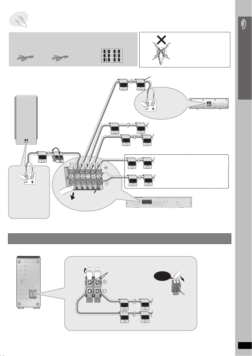
STEP3 Speaker connections
[HT995]
Speaker cables
≥ 2kshor t cable:
For center speaker
and subwoofer
6 SUBWOOFER
Push!
[HT995]
Insert the
wire fully.
i: White
j: Blue
This connection is
necessary only for
SC-HT995.
[HT995W]
Speaker cables
≥ 1kshort cable:
For center speaker
SUB
WOOFER
6
Push!
2 sheets of speaker cable stickers
≥ Attach the speaker-cable stickers
to make connection easier.
CENTER
WOOFER
SUB
6
5
5
6
SUB
WOOFER
CENTER
SURROUND
SURROUND
Rch
Lch
3
4
4
3
Rch
SURROUND
SURROUND
FRONT
FRONT
Rch
Lch
2
1
1
2
Lch Lch
Rch
FRONT
FRONT
CENTER
5
FRONT
Rch
2
FRONT
Lch
1
SURROUND
Rch
4
SURROUND
Lch
Insert the wire fully.
i: White
j: Blue
Be careful not to cross (shortcircuit) or reverse the polarity of
the speaker wires as doing so
may damage the speakers.
Simple Setup
The illustration shows SC-HT995.
Speaker cable sticker
CENTER
5
Insert the
wire fully.
i: White
j: Blue
Push!
2 FRONT (R)
FRONT
Rch
2
1 FRONT (L)
FRONT
Lch
1
4 SURROUND (R)
SURROUND
Rch
4
3 SURROUND (L)
SURROUND
Lch
3
3
Main unit
5 CENTER
Speaker connections
[HT995W]
Connect the surround
speaker cables to the
wireless system
(➜ below).
[HT995W] Connecting the surround speaker cables to the wireless system
Wireless system
R
L
Insert the wire fully.
i: White
j: Blue
SURROUND
Rch
4
SURROUND
Lch
3
4 SURROUND (R)
SURROUND
Rch
4
3 SURROUND (L)
SURROUND
Lch
3
Click!
RQT8766
11
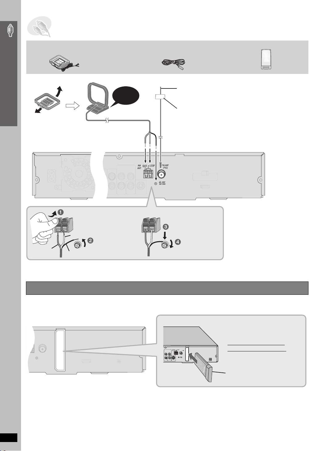
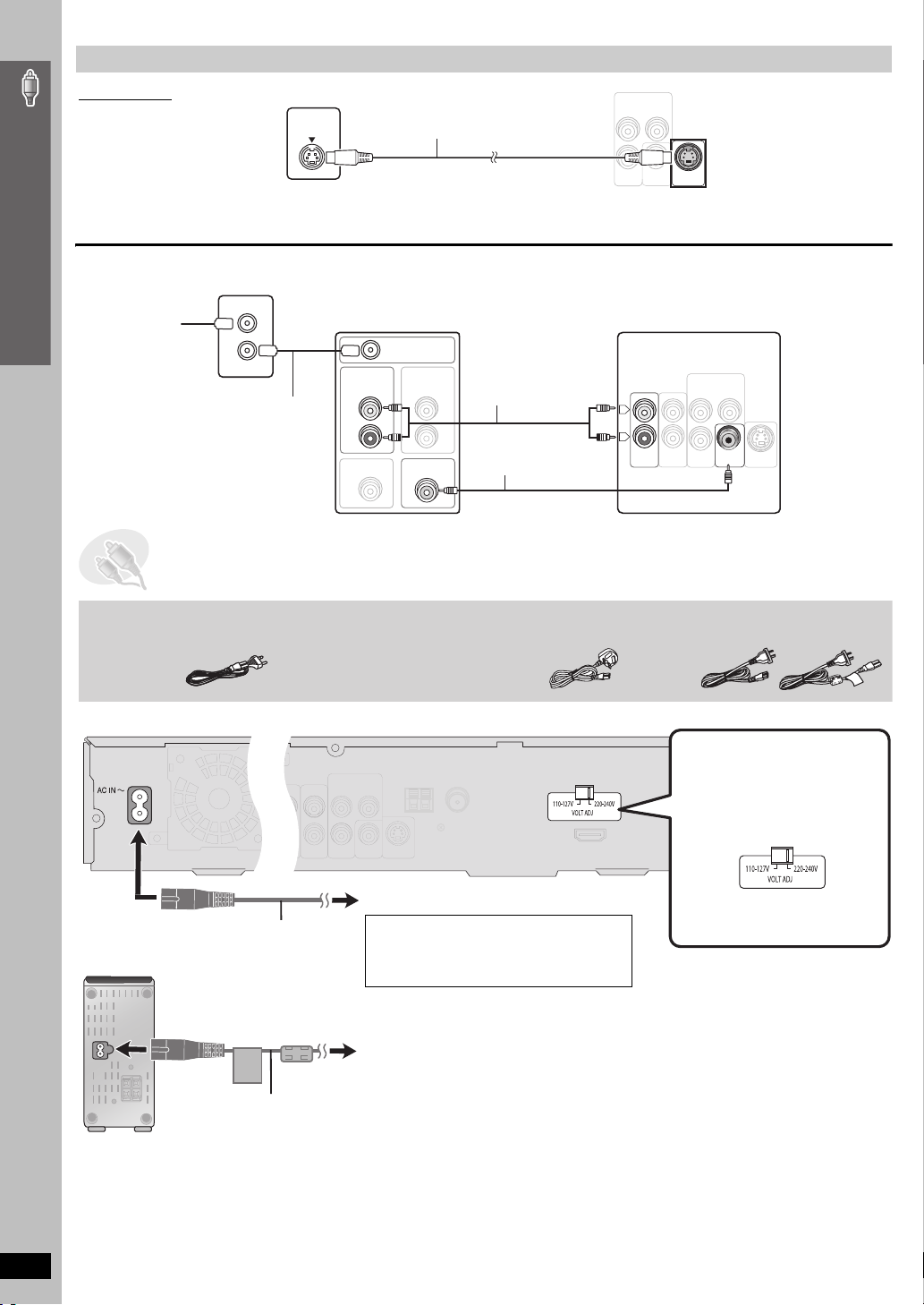
STEP4 Radio and digital transceiver connections
75
AM loop antenna FM indoor antenna
Simple Setup
≥ Using an outdoor antenna (optional) (➜ page 33).
AM loop antenna
Stand the antenna up on its base.
Place the antenna where reception is best.
Keep loose antenna cable away from other wires
and cables.
While pushing, insert the wire fully.
Click!
[HT995W] Digital transceiver
The illustration shows SC-HT995.
FM indoor antenna
Affix this end of the antenna where
reception is best.
Adhesive tape
Main unit
Radio and digital transceiver connections
Red
White
Black
Loosen the terminal
screw with a Phillipshead screwdriver.
Re-tighten the
terminal screw.
[HT995W] Connecting the digital transceiver
Digital Transceiver
Main unit
FM ANT
COMPONENT VIDEO OUT
Y
B
P
R
P
VIDEO
Digital Transceiver
S-VIDEO
OUT
OUT
Insert the digital transceiver
into the slot.
Do not insert or remove
while the main unit is on.
Digital transceiver
Insert fully until you hear a click.
12
RQT8766
STEP5 Audio and video connections
IN
AUDIO
TV
VID EO
OUT
≥ Do not connect through the video cassette recorder.
Due to copy guard protection, the picture may not be displayed properly.
Video cable
≥ Turn the television off before connecting, and refer to the television’s operating instructions.
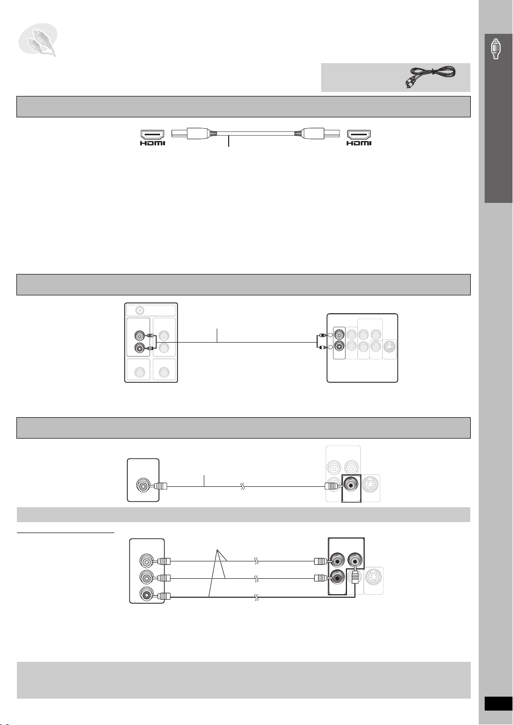
Television with an HDMI terminal
HDMI-compatible television
(not included)
AV IN AV OUT
HDMI cable (not included)
Use the HDMI connection to enjoy higher quality audio and video with a single cable (➜ page 43, HDMI).
≥ Set “Video Output” to “On” and “Audio Output” to “On” (➜ page 30, “HDMI” tab).
≥ Set “Video Output Mode” (➜ page 25, Picture Menu).
Back of the main unit
Control with HDMI (HDAVI Control)
If your Panasonic television is an HDMI control compatible television, you can operate your television synchronizing with home-theater operations or
vice versa [➜ page 39, Operating both the television and the home theater system: Control with HDMI (HDAVI Control
[Note]
≥ Make the extra audio connection (➜ below) when you use HDAVI Control function.
≥ It is recommended that you use Panasonic’s HDMI cable.
[Recommended part number: RP-CDHG15 (1.5 m), RP-CDHG30 (3.0 m), RP-CDHG50 (5.0 m), etc.]
≥ Non-HDMI-compliant cables cannot be utilized.
TM
)].
Basic audio connection
Television
(not included)
AUDIO
OUT
L
R
VIDEO OUT
RF IN
AUDIO
IN
VIDEO IN
Audio cable
(not included)
OUT
Y
S-VIDEO
OUT
Back of the
main unit
COMPONENT VIDEO OUT
L
R
AUDIO
P
B
P
TV
IN
R
VIDEO
AUX
Simple Setup
Audio and video connections
≥ This audio connection will enable you to play audio from your television through your home theater system.
Refer to “Operating other equipment” (➜ page 38).
≥ You can also connect to the AUX terminals on the main unit. The TV AUDIO IN and AUX terminals are for external audio input.
Basic video connection
COMPONENT VIDEO OUT
Television
(not included)
VIDEO IN
Video cable
(included)
Other video connections for improved picture quality
COMPONENT VIDEO OUT
Television
(not included)
COMPONENT
VIDEO IN
Video cables (not included)
PB
PR
Y
≥ Using the COMPONENT VIDEO OUT terminals
The COMPONENT VIDEO OUT terminals provides a purer picture than the S-VIDEO OUT terminal. These terminals can be used for either
interlaced or progressive output. Connection using these ter minals outputs the color difference signals (P
order to achieve high fidelity in reproducing colors.
≥ The description of the component video input terminals depends on the television or monitor (e.g. Y/P
Connect to terminals of the same color.
To enjoy progressive video
≥ Connect to a progressive output compatible television.
1 Set “Video Output” to “Off” (➜ page 30, “HDMI” tab).
2 Set “Video Output Mode” to “480p” or “576p”, and then follow the instructions on the menu screen (➜ page 25, Picture Menu).
COMPONENT VIDEO OUT
B/PR, Y/B-Y/R-Y, Y/CB/CR).
Back of the
main unit
Y
P
B
P
R
VIDEO
S-VIDEO
OUT
OUT
Back of the
main unit
Y
P
B
P
R
VIDEO
S-VIDEO
OUT
OUT
B/PR) and luminance signal (Y) separately in
(Continued on next page)
RQT8766
13
Other video connections for improved picture quality
IN
TV
AUDI O
VID EO
OUT
S-VIDEO OUT
Television
(not included)
S-VIDEO
IN
S-video cable
(not included)
COMPONENT VIDEO OUT
≥Using the S-VIDEO OUT terminal
The S-VIDEO OUT terminal achieves a more vivid picture than the VIDEO OUT terminal by separating the chrominance (C) and luminance (Y)
Simple Setup
signals. (Actual results depend on the television.)
P
B
P
R
VIDEO
OUT
Y
Back of the
main unit
S-VIDEO
OUT
∫ Cable TV box or video cassette recorder connection
Cable TV box or video cassette recorder (not included)
To y o u r
cable TV
service or
television
antenna
RF IN
RF OUT
RF cable
(not included)
Television (not included)
RF IN
AUDIO
OUT
AUDI O
IN
L
R
VIDEO OUT
VIDEO IN
Audio cable
(not included)
Video cable
(included)
Back of the main unit
COMPONENT VIDEO OUT
LL
RR
TV
AUDI O
IN
P
B
P
R
AUX
VIDEO
OUT
Y
S-VIDEO
OUT
STEP6 AC mains lead connections
AC mains lead
[Southeast[Asia,[
Thailand,[the[Middle[East,[South[Africa,[[Saudi[Arabia[and[Kuwait[
[Saudi[Arabia[and[Kuwait[
[HT995W]
2 AC mains leads
You can use the
AUX term in al for
the audio input
when you connect
another external
device (e.g. video
cassette
recorder). Select
“AUX” as the input
source
(SELECTOR
➜ page 16).
14
≥ Connect the AC mains lead after all other connections are complete.
The illustration shows SC-HT995.
[Southeast[Asia,[Thailand,[the[Middle[East,[
[South[Africa,[Saudi[Arabia[and[Kuwait[
Before connecting the AC
mains lead
Audio and video connections / AC mains lead connections
[HT995W]
AC mains lead
To household mains socket
[Saudi[Arabia[and[Kuwait[
BE SURE TO READ THE CAUTION FOR
THE AC MAINS LEAD ON PAGE 4
BEFORE CONNECTION.
Main unit
Set the voltage.
Change the voltage selector to the
appropriate position for the area in
which this system is used.
Wireless system
AC IN~
AC mains lead
Conserving power
The main unit and the wireless system consume a small amount of power when they are in standby mode (main unit: For Southeast Asia, Thailand,
the Middle East, South Africa, Saudi Arabia and Kuwait: approx. 0.65 W or for Australia and N.Z.: approx. 0.5 W, [HT995W] wireless system: approx.
4 W). To save power when they are not to be used for a long time, unplug them from the household mains socket.
You will need to reset some memory items after plugging in the main unit.
[Note]
RQT8766
The included AC mains leads are for use with the main unit and wireless system only. Do not use them with other equipment. Also, do not use cords
for other equipment with the main unit or wireless system.
To household mains socket
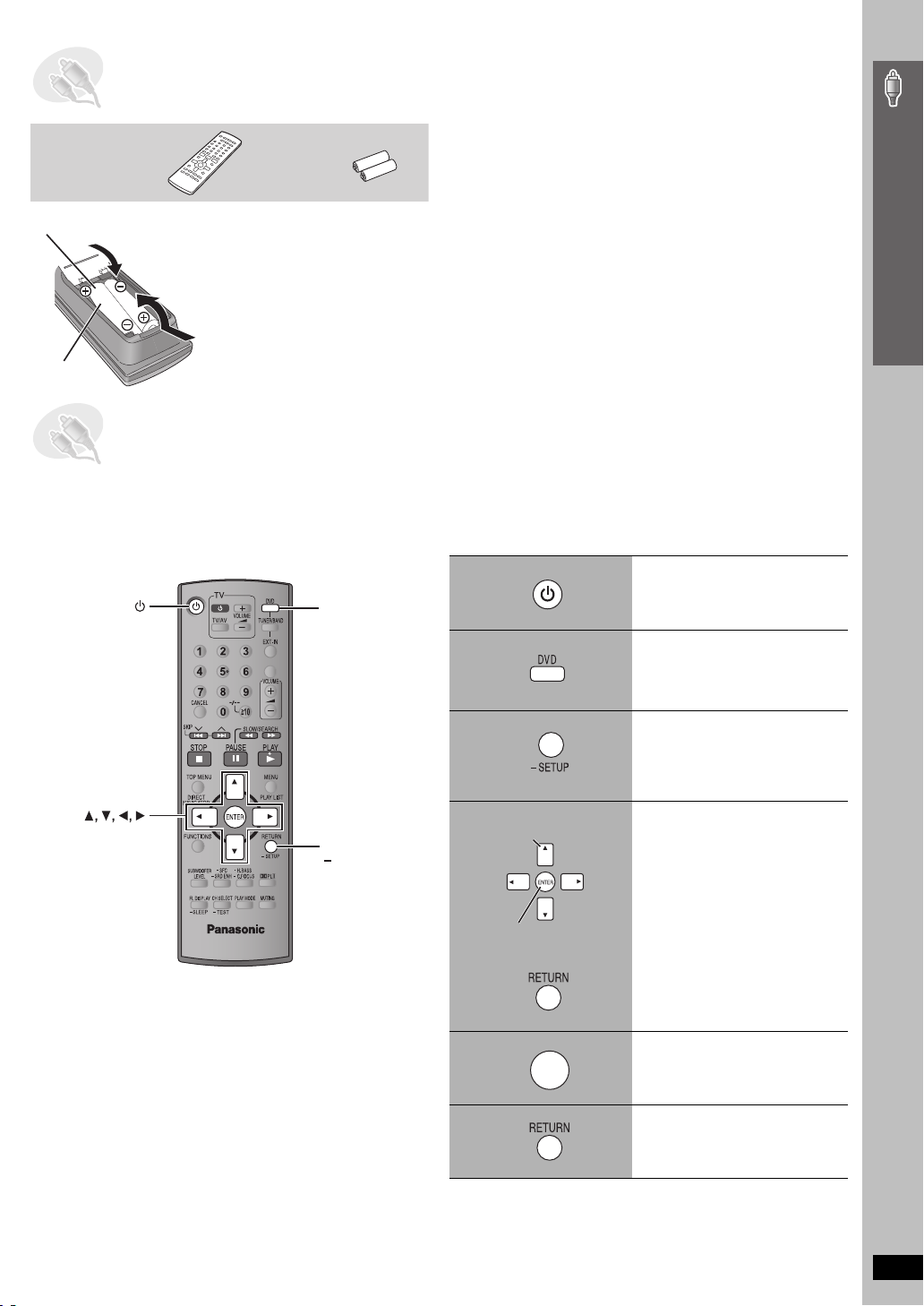
STEP7 Preparing the remote control
Remote control Batteries
Insert so the poles (i and j) match those in the remote control.
2
3
≥ Do not use rechargeable type
1
R6/LR6, AA
batteries.
Do not:
≥ mix old and new batteries.
≥ use different types at the same time.
≥ heat or expose to flame.
≥ take apart or short circuit.
≥ attempt to recharge alkaline or manganese batteries.
≥ use batteries if the covering has been peeled off.
Mishandling of batteries can cause electrolyte leakage which can
severely damage the remote control.
Remove the batteries if the remote control is not going to be used for a
long period of time. Store in a cool, dark place.
∫ Use
Aim at the remote control signal sensor (➜ page 16), avoiding
obstacles, at a maximum range of 7 m directly in front of the unit.
STEP8 Performing QUICK SETUP
The QUICK SETUP screen assists you to make necessary settings.
To display the picture from the main unit, turn on your television and change its video input mode (e.g. VIDEO 1, AV 1, etc.).
≥ To change your television’s video input mode, refer to its operating instructions.
≥ This remote control can perform some basic television operations (➜ page 38).
1
DVD
Turn on the unit.
Simple Setup
ENTER
ONE TOUCH PLAY
RETURN,
SETUP
2
3
Select “DVD/CD”.
Press and hold to show
the QUICK SETUP
screen.
4
Select
Register
5
ENTER
6
Follow the messages
and make the settings.
Press to finish QUICK
SETUP.
Press repeatedly to exit.
Preparing the remote control / Performing QUICK SETUP
To change these settings later
Select “QUICK SETUP” in the “Others” tab (➜ page 30).
RQT8766
15
 Loading...