

Panasonic SC-HT920 User Manual
Before connecting, operating or adjusting this product,
please read these instructions completely.
Please keep this manual for future reference.
Region number
The player plays DVD-Video marked with labels containing “1” or
“ALL”.
Example:
1
1 ALL
2
4
Operating Instructions
DVD Home Theater Sound System
Model No. SC-HT920
Table of contents
Getting started
IMPORTANT SAFETY INSTRUCTIONS . . . . . . . . 3
Accessories . . . . . . . . . . . . . . . . . . . . . . . . . . . . . . 3
Simple setup
STEP 1 Front speaker assembly . . . . . . . . . . 4
Other speaker setup options . . . . . . 5
STEP 2 Locating . . . . . . . . . . . . . . . . . . . . . . . 6
STEP 3 Connecting speakers with the
subwoofer . . . . . . . . . . . . . . . . . . . . . . 7
STEP 4 Video connections . . . . . . . . . . . . . . . 8
STEP 5 Radio and system connection . . . . . 9
STEP 6 The remote control. . . . . . . . . . . . . . . 9
STEP 7 QUICK SETUP. . . . . . . . . . . . . . . . . . 10
As an ENERGY STAR Partner,
Panasonic has determined that
this product meets the ENERGY STAR
guidelines for energy efficiency.
§
For Canada only: The word “Participant” is used in place of the
word “Partner”.
®
®
Control reference guide . . . . . . . . . . . . . . . . . . . 10
Discs that can be played. . . . . . . . . . . . . . . . . . . 11
Main unit and disc caution . . . . . . . . . . . . . . . . . 11
Disc operations
Basic play . . . . . . . . . . . . . . . . . . . . . . . . . . . . . 12
Convenient functions . . . . . . . . . . . . . . . . . . . . . 14
Position memory/Zoom/Audio/Subtitle/Quick replay/
Page skip/Repeat play/All group, random and program
play
Using navigation menus . . . . . . . . . . . . . . . . . . . 16
Playing data discs/Playing HighMATTM discs/Playing
the programs/Playing a play list
Using on-screen menus . . . . . . . . . . . . . . . . . . . 18
Changing the player settings . . . . . . . . . . . . . . . 20
Other operations
The radio. . . . . . . . . . . . . . . . . . . . . . . . . . . . . . . . 22
Automatic presetting/Selecting the preset channels/
Manual tuning/Optional antenna connections
Sound field and sound quality . . . . . . . . . . . .24-26
Sound Field Control/Super Surround/Center Focus/
Dolby Pro Logic II/Multi Rear Surround (MRS), Virtual
Rear Surround (VRS)/Down-mixing/Speaker level
adjustments/Subwoofer level/Custom Sound Memory
Other functions . . . . . . . . . . . . . . . . . . . . . . . . . . 27
Sleep timer/Muting/Using headphones
Operating other equipment. . . . . . . . . . . . . . . . . 28
P
PC
Reference
Specifications . . . . . . . . . . . . . . . . . . . . . . . . . . . 30
Troubleshooting guide . . . . . . . . . . . . . . . . . . . . 32
Product service/Maintenance/Glossary. . . . . . . 34
Limited Warranty (ONLY FOR U.S.A.) . . . . . . . . 35
RQT7696-2P
Dear customer
Thank you for purchasing this product. For optimum performance
and safety, please read these instructions carefully.
System SC-HT920
Main unit SA-HT920
Front speakers SB-PF920
Center speaker SB-PC920
Surround speakers SB-PS920
Active subwoofer SB-WA920
Operations in these instructions are described mainly with
the remote control, but you can perform operations on the
main unit if the controls are the same.
CAUTION!
THIS PRODUCT UTILIZES A LASER.
USE OF CONTROLS OR ADJUSTMENTS OR PERFORMANCE
OF PROCEDURES OTHER THAN THOSE SPECIFIED HEREIN
MAY RESULT IN HAZARDOUS RADIATION EXPOSURE.
DO NOT OPEN COVERS AND DO NOT REPAIR YOURSELF.
REFER SERVICING TO QUALIFIED PERSONNEL.
WARNING:
TO REDUCE THE RISK OF FIRE, ELECTRIC SHOCK OR
PRODUCT DAMAGE, DO NOT EXPOSE THIS APPARATUS
TO RAIN, MOISTURE, DRIPPING OR SPLASHING AND THAT
NO OBJECTS FILLED WITH LIQUIDS, SUCH AS VASES,
SHALL BE PLACED ON THE APPARATUS.
CAUTION!
DO NOT INSTALL OR PLACE THIS UNIT IN A BOOKCASE,
BUILT-IN CABINET OR IN ANOTHER CONFINED SPACE.
ENSURE THE UNIT IS WELL VENTILATED. TO PREVENT
RISK OF ELECTRIC SHOCK OR FIRE HAZARD DUE TO
OVERHEATING, ENSURE THAT CURTAINS AND ANY OTHER
MATERIALS DO NOT OBSTRUCT THE VENTILATION VENTS.
CAUTION
RISK OF ELECTRIC SHOCK
DO NOT OPEN
CAUTION: TO REDUCE THE RISK OF ELECTRIC
SHOCK, DO NOT REMOVE SCREWS.
NO USER-SERVICEABLE PARTS
INSIDE.
REFER SERVICING TO QUALIFIED
SERVICE PERSONNEL.
THE FOLLOWING APPLIES ONLY IN THE U.S.A.
CAUTION:
This equipment has been tested and found to comply with the
limits for a Class B digital device, pursuant to Part 15 of the FCC
Rules.
These limits are designed to provide reasonable protection
against harmful interference in a residential installation. This
equipment generates, uses and can radiate radio frequency
energy and, if not installed and used in accordance with the
instructions, may cause harmful interference to radio
communications. However, there is no guarantee that
interference will not occur in a particular installation. If this
equipment does cause harmful interference to radio or television
reception, which can be determined by turning the equipment off
and on, the user is encouraged to try to correct the interference
by one or more of the following measures:
≥Reorient or relocate the receiving antenna.
≥Increase the separation between the equipment and receiver.
≥Connect the equipment into an outlet on a circuit different from
that to which the receiver is connected.
≥Consult the dealer or an experienced radio/TV technician for
help.
Any unauthorized changes or modifications to this equipment
would void the user’s authority to operate this device.
This device complies with Part 15 of the FCC Rules. Operation is
subject to the following two conditions: (1) This device may not
cause harmful interference, and (2) this device must accept any
interference received, including interference that may cause
undesired operation.
RQT7696
2
The lightning flash with arrowhead symbol, within
an equilateral triangle, is intended to alert the user
to the presence of uninsulated “dangerous voltage”
within the product’s enclosure that may be of sufficient magnitude to constitute a risk of electric shock
to persons.
The exclamation point within an equilateral triangle
is intended to alert the user to the presence of
important operating and maintenance (servicing)
instructions in the literature accompanying the appliance.
(Inside of product)
IMPORTANT SAFETY INSTRUCTIONS
Read these operating instructions carefully before using the unit. Follow the safety instructions on the unit and the applicable safety instructions
listed below. Keep these operating instructions handy for future reference.
1) Read these instructions.
2) Keep these instructions.
3) Heed all warnings.
4) Follow all instructions.
5) Do not use this apparatus near water.
6) Clean only with dry cloth.
7) Do not block any ventilation openings. Install in accordance with
the manufacturer’s instructions.
8) Do not install near any heat sources such as radiators, heat
registers, stoves, or other apparatus (including amplifiers) that
produce heat.
9) Do not defeat the safety purpose of the polarized or groundingtype plug. A polarized plug has two blades with one wider than
the other. A grounding-type plug has two blades and a third
grounding prong. The wide blade or the third prong are
provided for your safety. If the provided plug does not fit into
your outlet, consult an electrician for replacement of the
obsolete outlet.
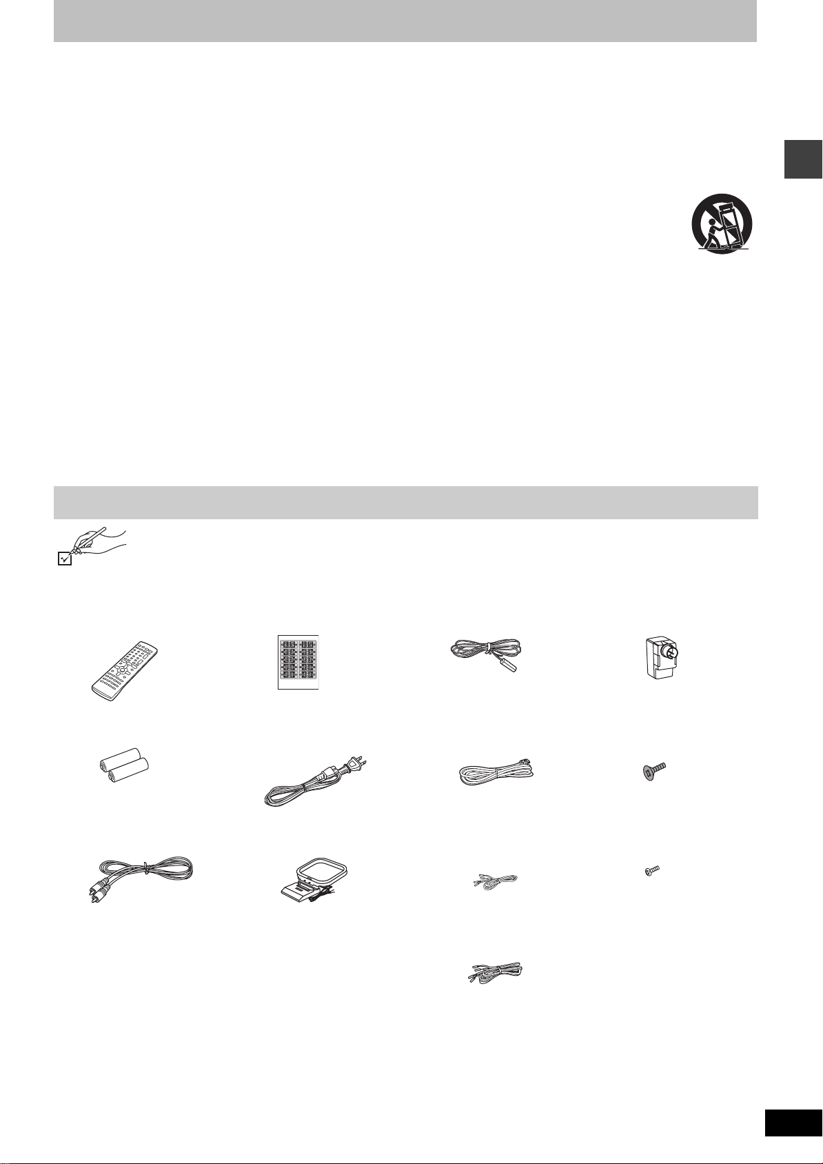
Accessories
Please check and identify the supplied accessories. Use numbers indicated in parentheses when asking for replacement parts.
Only for U.S.A.: To order accessories, refer to “Accessory Purchases” on page 35.
For other areas: To order accessories, call the dealer from whom you made your purchase.
10) Protect the power cord from being walked on or pinched
particularly at plugs, convenience receptacles, and the point
where they exit from the apparatus.
11) Only use attachments/accessories specified by the
manufacturer.
12) Use only with the cart, stand, tripod, bracket, or
table specified by the manufacturer, or sold with
the apparatus. When a cart is used, use caution
when moving the cart/apparatus combination to
avoid injury from tip-over.
13) Unplug this apparatus during lightning storms or when unused
for long periods of time.
14) Refer all servicing to qualified service personnel. Servicing is
required when the apparatus has been damaged in any way,
such as power-supply cord or plug is damaged, liquid has been
spilled or objects have fallen into the apparatus, the apparatus
has been exposed to rain or moisture, does not operate
normally, or has been dropped.
IMPORTANT SAFETY INSTRUCTIONS/Accessories
∏ 1 Remote control
(EUR7722X50)
∏ 2 Remote control batteries
∏ 1 Video cable
(RJL1P016B15A)
∏ 1 Sheet of speaker-cable
stickers
∏ 1 AC power supply cord
(K2CB2CB00006)
∏ 1 AM loop antenna
(N1DAAAA00001)
∏ 1 FM indoor antenna
(RSA0007-J)
∏ 1 System cable
(K1HA25HA0001)
∏ 3 Speaker cables
4-m (13-foot) cable
(REE1203A-J)
2k10-m (33-foot) cables
(REE1203C-J)
∏ 1 Antenna plug
(K2RC021B0001)
∏ 4 Large screws
(XSS6+14FZ)
∏ 4 Small screws
(XSN5+10FN)
[Note]
The included AC power supply
cord is for use with this unit only.
Do not use it with other
equipment.
RQT7696
3
Simple setup
STEP1
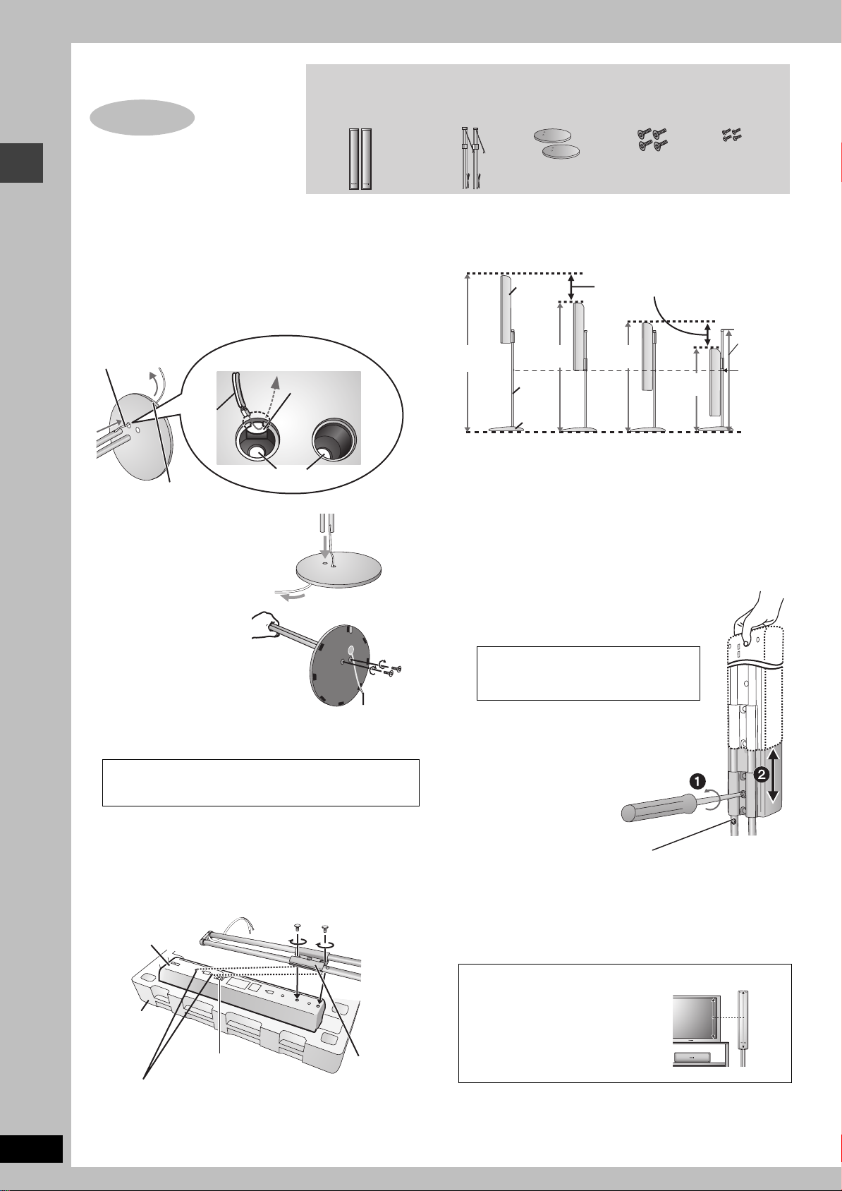
Front speaker assembly
Make sure you have all the indicated components before starting assembly, setup, and
connection.
Front speaker units
Pipes
Bases
Large screws
Small screws
Preparation
≥To prevent damage or scratches, lay down a soft cloth and
perform assembly on it.
≥For assembly, use a Phillips-head screwdriver.
1 Attach the pipe to the base.
1 Thread the speaker cable through the base.
Front speaker assembly
Lessen excess
speaker cable.
Cable
Groove
2 Insert the pipe.
Insert the pipe while gently
pulling on the speaker cable.
3
Secure the pipe to the base.
Ensure the screws are
securely fastened by lightly
tightening the left and right
side screws alternately until
fully tightened. (The heads
of the screws protrude
slightly even if you have fully
tightened them.)
The supplied stands are specially designed for
attachment to Panasonic SB-PF920 front speakers.
Only use as indicated in this setup.
Holes for screws
Thread the
speaker cable
through here.
Rear side of base
Large
screws
Cable
∫ Front speaker height
(Assembled diagram)
1,138 mm
13
(44
/16z)
Speaker
968 mm
1
(38
/8z)
Pipe
Base
Attach to lower
rear of speaker
You can adjust within this range.
678 mm
(26
796 mm
11
(31
/32z)
Attach to upper
rear of speaker
625 mm
19
(24
/32z)
Stopper
screw
Do not
remove.
11
/16z)
3 Adjust the speaker height.
≥Check the screws you tightened in procedures 1 and 2 if the pipe
and speaker are loose.
e.g. Attaching the stand to the lower rear
1 Loosen the attached speaker mounting
plate screw until the attached speaker is
slightly loose and adjustable.
Be careful not to loosen the screw
too much or the speaker may detach
and fall.
2 With one hand on the base and the other
holding the speaker adjust the height of
the speaker up and down.
≥After adjusting the height tighten the screw
on the mounting plate securely.
Phillips-head screwdriver
2 Attach the stand to the speakers.
≥
There is no difference between the right and left speakers and stands.
≥Using the polyfoam included with this unit may be convenient.
Ensure the stand is fastened on straight by lightly tightening the top
and bottom screws alternately until fully tightened.
Small screws
Front speaker
Stopper screw
Screw to stop mounting plate from
moving or sliding below this point.
RQT7696
4
Poly foam
Connection terminals
You can also attach to the upper rear of the speaker.
The height of the speaker is indicated in the diagram on the
right when attaching the stand to the upper rear or lower rear of
the speaker.
Mounting
plate
For your reference
You can enjoy good acoustics by
adjusting the height of the speaker to
the height of the television so the
center positions of both are
approximately the same.
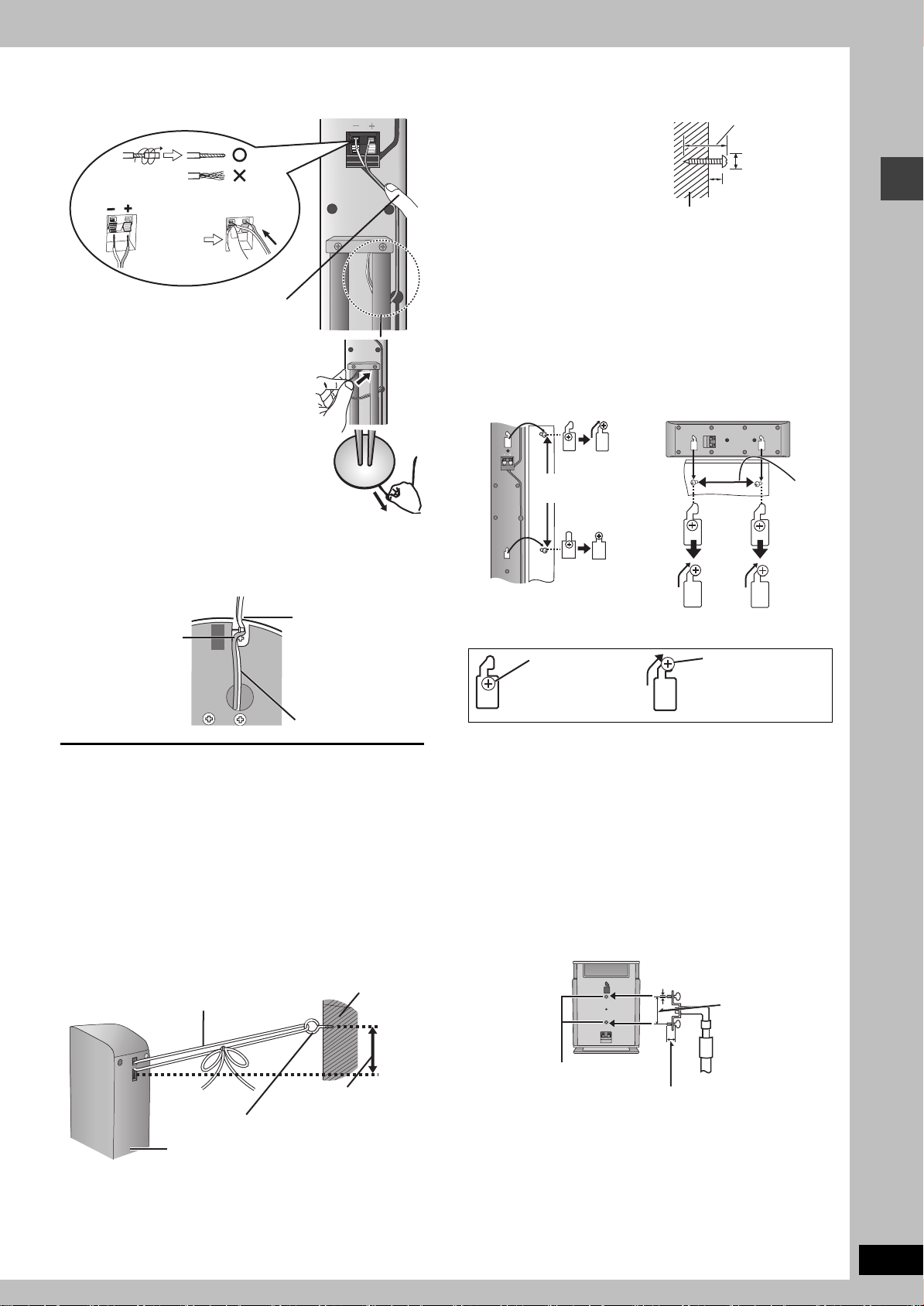
4 Connect the speaker cables.
1
Twist off the vinyl ends of the
speaker cables.
_: Copper
`: Silver
Push !
2 Press the speaker cable into the groove.
If there is any excess
speaker cable, thread the
speaker cable into the
opening near the top of the
pipe while pulling the
speaker cable from the
bottom of the base.
Rear of the speaker
Other speaker setup options
∫ Attaching to a wall
1 Drive a screw (not included)
into a wall.
2 Fit the speaker securely onto
the screw(s) with the hole(s).
Wall or pillar
≥
The wall or pillar on which the speakers are to be attached should be
capable of supporting 10 k
building contractor when attaching the speakers to a wall. Improper
attachment may result in damage to the wall and speakers.
≥When mounting the front speaker to a wall, we recommend using
a string (not included) to prevent it from falling ( ‹ left).
≥Use of optional speaker cables is recommended for wall mounted
front speakers. (You can also remove the speaker cables from the
pipes supplied with this system).
e.g.
Front speaker Center speaker
g
(22 lb.) per screw. Consult a qualified
30–35 mm
3
(1
‰7.5–9.4 mm
19
(
8– 11 mm
3
(
/8q–7/16q)
/16q–13/8q)
/64q–3/8q)
5 Fasten the speaker cable to the base.
≥Using the same polyfoam as in procedure 2 will assist you in
safely and securely fastening the speaker cables.
1 Press the speaker
cable and thread
between the
hooks.
Rear side of base
∫ Preventing the speakers from falling over
Preparation
Attach screw eyes (not included) to secure the speakers to the wall
(‹diagram below)
≥You will need to obtain the appropriate screws to match the walls
and pillars to which the screw eyes are going to be fastened.
≥Consult with a qualified housing contractor concerning the
appropriate procedure when attaching to a concrete wall or a
surface that may not have strong enough support. Improper
attachment may result in damage to the wall or speakers.
1 Thread the string (not included) through the slot on the
rear of the speaker to prevent it from falling over.
2 Loop the string through the screw eye and tie tightly.
e.g.
String (not included)
2 Fit the speaker
cable into the
base cover groove
as far as possible.
Cable
Wall
230 mm
1
(9
/16z)
In this position, the
speaker will likely
fall if moved to the
left or right.
Move the speaker
so the screw is in
this position.
150 mm
29
(5
/32z)
∫ Fitting speaker stands (not included)
Ensure the stands meet these conditions before purchasing them.
Note the diameter and length of the screws and the distance
between screws as shown in the diagram.
≥The stands must be able to support over 10 kg (22 lb.).
≥
The stands must be stable even if the speakers are in a high position.
e.g. Surround speaker
13
5 mm (
pitch 0.8 mm (
/64z),
60 mm (2
1
/32z)
23
/64z)
Front speaker assembly/Other speaker setup options
Screw eye (not included)
Rear of the speaker
Approx. 150 mm
15
/16z)
(5
Attach the stands to
these metal screw
holes.
Speaker stand
(not included)
Plate thickness plus 7 to 10 mm
9
/32z to 25/64z)
(plus
RQT7696
5
How you set up your speakers can affect the bass and the sound field. Note the following points.
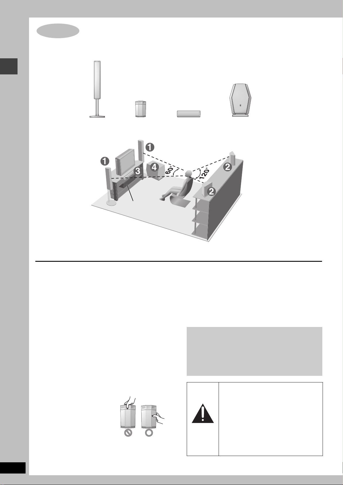
STEP2 Locating
≥Place speakers on flat secure bases.
≥Placing speakers too close to floors, walls, and corners can result in excessive bass. Cover
walls and windows with thick curtains.
≥The left and right speaker pairs are the same with respect to the front and surround speakers.
Locating
RQT7696
6
1
FRONT
(L, R)
≥Place the front, center, and surround speakers at approximately the same distance from the seating position.
The angles in the diagrams are approximate.
2
SURROUND
(L, R)
Setup example
Main unit
≥Use only supplied speakers
Using other speakers can damage the unit and sound quality will
be negatively affected.
≥Set the speakers up on an even surface to prevent them from
falling. Take proper precautions to prevent the speakers from
falling if you cannot set them up on an even surface.
Main unit
[Note]
Keep your speakers at least 10 mm (13/32q) away from the system
for proper ventilation.
Center speaker
≥Vibration caused by the center speaker can disrupt the picture if it
is placed directly on the television. Put the center speaker on a
rack or shelf.
≥To prevent the speakers from falling, do not place directly on top
of the television.
Subwoofer
Place to the right or left of the television, on the floor or a sturdy
shelf so that it won’t cause vibration. Leave 10 cm (4q) at the rear
for ventilation.
3
CENTER
Notes on speaker use
≥You can damage your speakers and shorten their useful life if you
play sound at high levels over extended periods.
≥Reduce the volume in the following cases to avoid damage.
– When playing distorted sound.
– When the speakers are receiving howling from a record player,
noise from FM broadcasts, or continuous signals from an
oscillator, test disc, or electronic instrument.
– When adjusting the sound quality.
– When turning the unit on or off.
If irregular coloring occurs on your television
The supplied speakers are designed to be used close to a
television, but the picture may be affected with some televisions
and setup combinations.
If this occurs, turn the television off for about 30 minutes.
The television’s demagnetizing function should correct the
problem. If it persists, move the speakers farther away from the
television.
Caution
≥Do not touch the netted area of the
surround speakers.
4
SUBWOOFER
Caution
≥The main unit and supplied speakers are
only to be used as indicated in this setup.
Failure to do so may lead to damage to the
amplifier and/or the speakers, and may
result in the risk of fire. Consult a qualified
service person if damage has occurred or if
you experience a sudden change in
performance.
≥Do not attempt to attach these speakers to
walls using methods other than those
described in this manual.
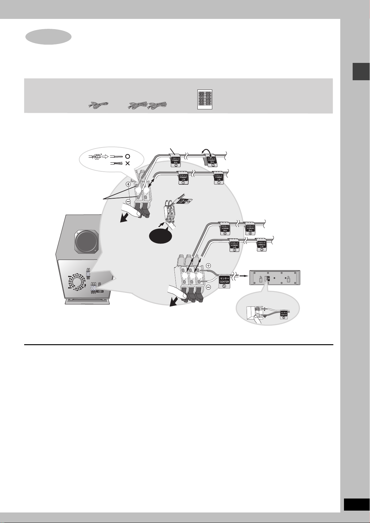
STEP3 Connecting speakers with the subwoofer
≥Attach the speaker-cable stickers to make connection easier.
≥The terminals of the subwoofer have high output power. Carefully connect the speaker wires.
Speaker cables
≥4 m (13-foot) cables: For center speaker
≥10 m (33-foot) cables: For surround speakers
Speaker-cable sticker
2
1
Insert the wire fully.
Click!
Sheet of speaker-cable stickers
2 FRONT (R)
1 FRONT (L)
Connecting speakers with the subwoofer
4 SURROUND (R)
3 SURROUND (L)
5 CENTER
4
3
5
_:
Copper
Silver
`:
SUBWOOFER
[Note]
≥Never short-circuit positive (i) and negative (j) speaker wires.
≥Be sure to connect only positive (copper) wires to positive (i) terminals and negative (silver) wires to negative (j) terminals. Incorrect
connection can damage the speakers.
RQT7696
7
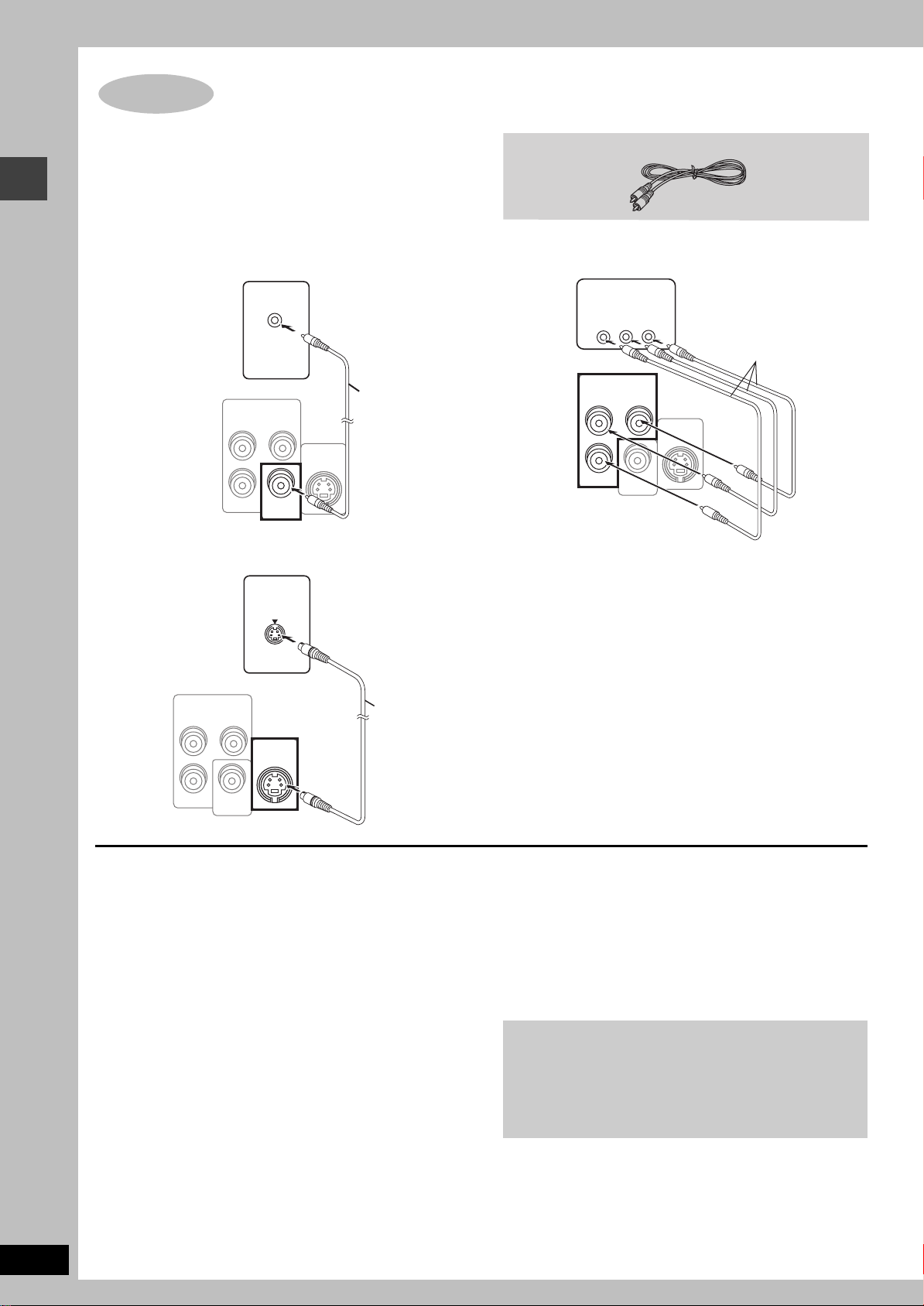
STEP4 Video connections
e
Video connections
≥Do not connect through the video cassette recorder.
Due to copy guard protection, the picture may not be displayed
properly.
≥Turn the television off before connecting, and refer to the
television’s operating instructions.
∫ Television with a VIDEO IN terminal
Television
(not included)
Back of the
main unit
VIDEO IN
COMPONENT
VIDEO OUT
(480P/480I)
B
P
R
VIDEO
OUT
YP
S-VIDEO
OUT
Video cable
(included)
∫ Television with an S-VIDEO IN terminal
Television
(not included)
S-VIDEO
IN
Video cable
∫
Television with COMPONENT VIDEO IN terminals
COMPONENT
VIDEO IN
PR
PB
Tel ev ision
(not included)
Y
Video cables
(not included)
COMPONENT
VIDEO OUT
B
P
R
(480P/480I)
VIDEO
OUT
YP
S-VIDEO
OUT
Back of the main unit
Back of the
main unit
COMPONENT
VIDEO OUT
(480P/480I)
B
P
R
VIDEO
OUT
YP
S-VIDEO
OUT
S-video cabl
(not included)
S-VIDEO OUT terminal
The S-VIDEO OUT terminal achieves a more vivid picture than the
VIDEO OUT terminal by separating the chrominance (C) and
luminance (Y) signals. (Actual results depend on the television.)
COMPONENT VIDEO OUT terminals
These terminals can be used for either interlace or progressive
output and provide a purer picture than the S-VIDEO OUT
terminal. Connection using these terminals outputs the color
difference signals (P
B/PR) and luminance signal (Y) separately in
order to achieve high fidelity in reproducing colors.
≥The description of the component video input terminals depends
on the television or monitor (e.g. Y/P
B/PR, Y/B-Y/R-Y, Y/CB/CR).
Connect to terminals of the same color.
≥After making this connection, select “Darker” from the “Black
Level Control” in the “Video” tab (‹ page 20).
.
To enjoy progressive video
≥Connect to the component video input terminals on a 480P
compatible television. (Video will not be displayed correctly if
connected to an incompatible television.)
≥All Panasonic televisions that have 480P input connectors
are compatible. Consult the manufacturer if you have
another brand of television.
RQT7696
8
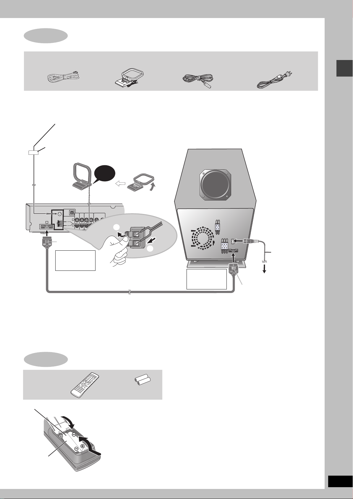
STEP5 Radio and system connection
System cable AM loop antenna FM indoor antenna AC power supply cord
≥Connect the AC power supply cord after all other connections are complete.
≥Optional antenna connections (‹ page 23).
FM indoor antenna AM loop antenna
Stand the antenna up on
its base. Place the
Adhesive tape
Affix this end of the antenna
where reception is best.
Main unit
OPTICAL
FM ANT
(75h)
AM ANT
A
LOOP
EXT
VCR
IN
AUDIO
AUX
IN
L
R
TV
AUDIO
IN
Click!
COMPONENT VIDEO OUT
LINE
(480P/480I)
OUT
B
P
R
VIDEO
OUT
antenna where
reception is best.
Keep loose antenna
cable away from other
wires and cables.
YP
S-VIDEO
OUT
1
Subwoofer
Radio and system connection/The remote control
Catch up
To disconnect
2
Press the catch
AC powe r
supply cord
and pull out.
System cable
To disconnect
Press the catch
and pull out.
To household AC outlet
(AC 120 V, 60 Hz)
Catch up
Conserving power
The main unit consumes a small amount of power, even when it is turned off (approx. 0.5 W). To save power when the unit is not to be used
for a long time, unplug it from the household AC outlet.
You will need to reset some memory items after plugging in the unit.
STEP6 The remote control
Remote control Batteries
Insert so the poles (i and j) match those
2
in the remote control.
3
Do not:
≥mix old and new batteries.
≥use different types at the same time.
≥heat or expose to flame.
≥take apart or shor t circuit.
≥attempt to recharge alkaline or manganese batteries.
≥use batteries if the covering has been peeled off.
Mishandling of batteries can cause electrolyte leakage which can
damage items the fluid contacts and may cause a fire.
R6/LR6, AA, UM-3
1
≥Do not use
rechargeable type
batteries.
Remove if the remote control is not going to be used for a long
period of time. Store in a cool, dark place.
∫ Use
Aim at the sensor (‹ page 10), avoiding obstacles, at a maximum
range of 7 m (23 feet) directly in front of the unit.
RQT7696
9
STEP7 QUICK SETUP
The QUICK SETUP screen assists you to make necessary settings.
Turn on the television and select the appropriate video input on the television.
123 4 5 6
Select
r
SETUP
MUTING
ENTER
Register
RETURN
ENTER
SHIFT
r
DVD/CD
SHIFT
SETUP
MUTING
QUICK SETUP/Control reference guide
Turn on the
unit.
Select
“DVD/CD”.
Shows QUICK
SETUP screen.
To change these settings later
Select “QUICK SETUP” in “Others” tab (‹ page 21).
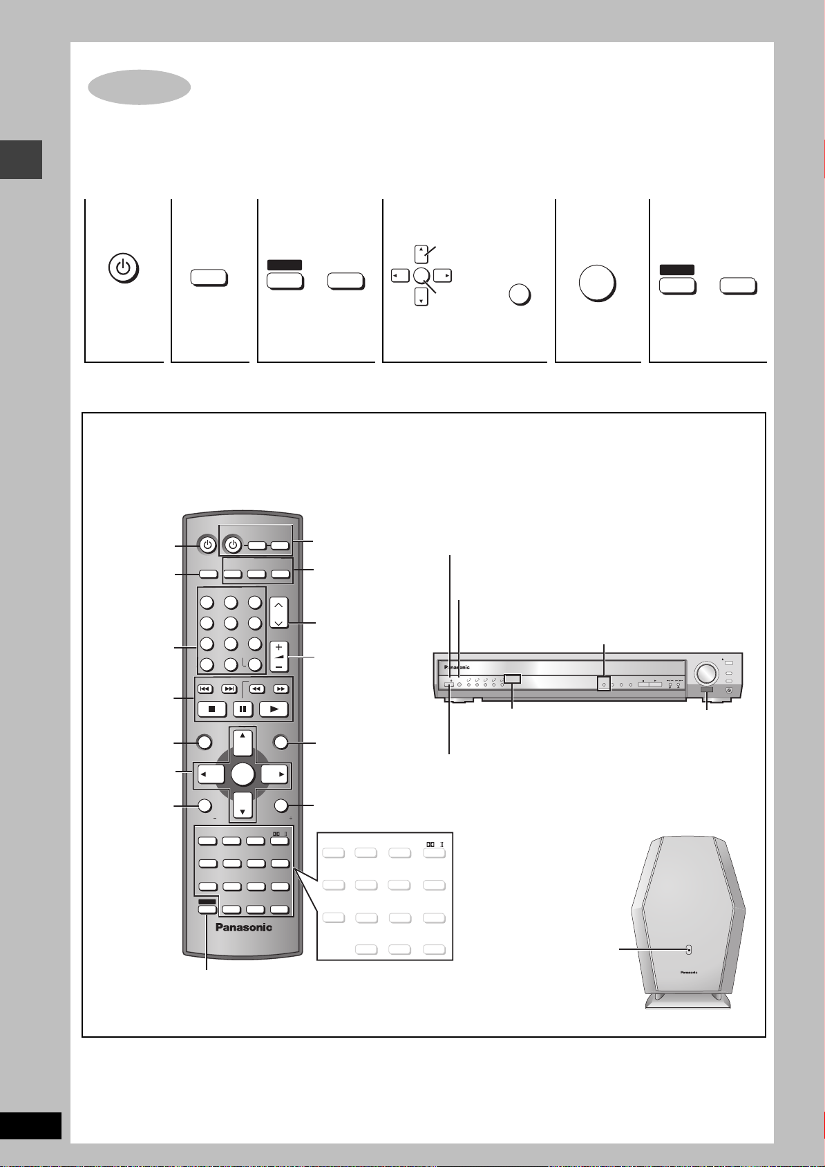
Control reference guide
See reference pages in brackets.
Power on/off
the unit.
Switch the
television’s
video input
mode.
(29)
(12, 13)
(12)
(13, 16, 17)
(10)
(18, 29)
AV SYSTEM
DIGITAL
AUX
TV/VIDEO
DISC 1 DISC 2 DISC 3
123
DISC 4 DISC 5
456
7809
CANCEL
SKIP
TOP MENU
TV
TUNER/BAND
ENTER
S10
SLOW/SEARCH
VCR
DVD/CD
CH
VOLUME
MENU
(29)
Select the source
DIGITAL, AUX (29)
TUNER/BAND (22)
DVD/CD (10)
(22, 29)
Adjust the
volume.
(13, 16, 17)
ENTER
C.FOCUS
SUPER SRND
AV EFFECT
CD MODE
QUICK REPLAY
ZOOM
AUDIO
PLAY
LIST
RETURN
TV VOL
MIX 2CH
PL
SETUP
MUTING
REPEAT
PLAY MODE
SUBTITLE
(13, 29)
SUBWOOFER
LEVEL
(26) (24) (24)
SLEEP
C.S.M
(26, 27)
FL DISPLAY
DIRECT
NAVIGATOR
DISPLAY
TV VOL
SUBWOOFER
LEVEL
SLEEP
C.S.M
FL DISPLAY
SHIFT
SFC
POSITION
MEMORY
PAG E
GROUP
TEST
CH SELECT
(13) (
To use functions labeled in orange:
While pressing [SHIFT], press the
corresponding button.
Follow the messages and
make the settings.
Standby/on indicator
When the unit is connected to the AC mains supply, this
indicator lights up in standby mode and goes out when the unit
is turned on.
Source select button [INPUT SELECTOR] (22)
DVD/CD#FM#AM#TV#VCR#AUX
D-IN (Digital In)#Return to DVD/CD
POWER
/I
Standby/on switch [Í/I, POWER]
Press to switch the unit from on to standby mode or vice versa. In
standby mode, the unit is still consuming a small amount of power.
C.FOCUS
SUPER SRND
ZOOM
AUDIO
AV EFFECT
CD MODE
(13, 25)
MIX 2CH
PL
(24, 25)
SETUP
MUTING
(20, 27)
REPEAT
PLAY MODE
SUBTITLE
SFC
POSITION
MEMORY
(14) (14)
PAG E
GROUP
12, 14
) (15)
TEST
QUICK REPLAY
CH SELECT
(25) (14) (14)
Press to
finish QUICK
SETUP.
Digital in button [DIGITAL IN] (29)
INPUT
1 2 3 4 5
SELECTOR
V.R.S, M.R.S indicators (25)
V.R.S M.R.S
5 DISC SELECTOR
AC supply indicator [AC IN]
This indicator lights when the
unit is connected to the AC
mains supply.
Press to exit.
#
VOLUME
PROGRESSIVE
C.S.M
DIGITAL IN
CD MODE
TUNE MODE
FM MODE MEMORY
Remote control signal sensor
DOWN
TUNING
PHONES
UP
OPEN/CLOSE
DISC EXCHANGE
DISC SKIP
RQT7696
10
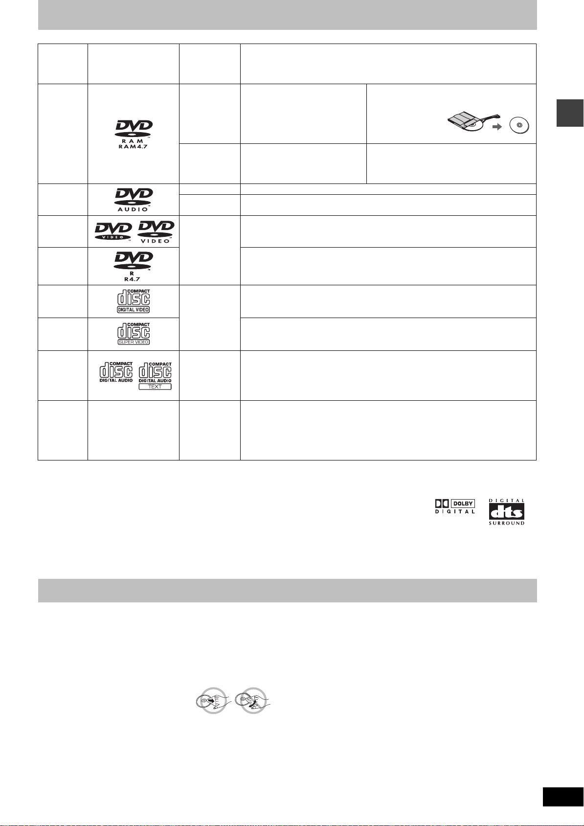
Discs that can be played
Disc Logo
DVD-RAM
DVD-Audio
DVD-Video
Indication
used in
operating
instructions
[RAM]
[JPEG]
[DVD-A] —
[DVD-V]
Remarks
Recorded using Version 1.1 of the
Video Recording Format (a unified
video recording standard).
Recorded using the DCF (Design
rule for Camera File system)
standard.
Some DVD-Audio discs contain DVD-Video content.
To play DVD-Video content, select “Play as DVD-Video” in Other Menu (‹ page 19)
—
≥Recorded with DVD-Video recorders, DVD-
Video cameras, personal computers, etc.
≥Remove TYPE 2
and 4 discs from
their cartridges
before use.
≥Recorded with Panasonic DVD-Video
recorders.
≥To play JPEG files, select “Play as Data Disc”
in Other Menu (‹ page 19).
[DVD-V]
DVD-R
Video CD
[VCD]
SVCD
CD [CD]
[WMA]
CD-R
CD-RW
§
A process that allows play on compatible equipment.
≥It may not be possible to play the above discs in all cases due to the type of disc or condition of the recording.
—
[MP3]
[JPEG]
[CD]
[VCD]
∫ Discs that cannot be played
PAL discs (except DVD-Audio), DVD-ROM, CD-ROM, CDV, CD-G,
DVD+R, iRW, DVD-RW, SACD, Divx Video Discs and Photo CD,
DVD-RAM that cannot be removed from their car tridge, 2.6-GB and
5.2-GB DVD-RAM, and “Chaoji VCD” available on the market
including CVD, DVCD and SVCD that do not conform to IEC62107.
Panasonic DVD-R recorded and finalized
DVD-Video cameras are played as DVD-Video on this unit.
—
Conforming to IEC62107
This unit is compatible with HDCD, but does not support the Peak Extend function.
(A function which expands the dynamic range of high level signals)
HDCD-encoded CDs sound better because they are encoded with 20 bits, as
compared with 16 bits for all other CDs.
≥During HDCD play, “HDCD” lights on the unit’s display.
≥This unit can play CD-R/RW (audio recording disc) recorded with the formats on
the left. Close the sessions or finalize
≥HighMAT discs
WMA, MP3 or JPEG files only.
To play without using the HighMAT function, select “Play as Data Disc” in Other
Menu (‹ page 19).
∫ Audio format of DVDs
This unit automatically recognizes
and decodes discs with these
symbols.
§
on Panasonic DVD-Video recorders or
§
the disc after recording.
Discs that can be played/Main unit and disc caution
Main unit and disc caution
∫ To prevent damage
Do not;
–load more than one disc per tray.
–touch the drawer or the carousel while they are in motion.
–rotate the carousel by hand.
–close the drawer by hand.
∫ To clean discs
[DVD-A] [DVD-V] [VCD[ [CD]
Wipe with a damp cloth and then wipe dry.
[RAM] [DVD-R]
≥Clean with an optional DVD-RAM/PD disc cleaner
(LF-K200DCA1, where available).
≥Never use cloths or cleaners for CDs, etc.
∫ Disc handling precautions
≥Do not attach labels or stickers to discs (This may cause disc
warping, rendering it unusable).
≥Do not write on the label side with a ball-point pen or other writing
instrument.
≥Do not use record cleaning sprays, benzine, thinner, static
electricity prevention liquids or any other solvent.
≥Do not use scratch-proof protectors or covers.
≥Do not use the following discs:
– Discs with exposed adhesive from removed stickers or labels
(rented discs, etc).
– Discs that are badly warped or cracked.
– Irregularly shaped discs, such as heart shapes.
RQT7696
11
 Loading...