


NV-J45
Table of contents
 Loading...
Vi
■frSi :■ V.
i;* ' '
■^Vv' V'
V 4-'^ ■'■■■?' i- i .'; i: ; v ir' :. , ■
V -V- V ;
.;. ;Ì ¥■'*■ i if- .5 ,'.. ,'.. .■: '.. ■ . .. .
¡: ¡;- f ji,.- V. „ i i '■ ■ ■ ■
■ ■ ' : .
-i- !:.-^ . :
-r ". - ■
; .; ••
^.. '1-. • 'K-
> i'., :
' i ,- -i ..
VfS.
f «■
Video Cassette Recorder
N V* J45series
Operating Instructions
;■■ ■■ .r? y ■■ 4-'... ■ ■■..■...
:■ is-'"" V- s: f f f f:--^; ;. ;.
- i» f. S.:f .i. i. .-
■ 4' i , , .
VMS
VQT4050
mu NTSC 4.43
Before attempting to connect, operate
or adjust this product, ptease read
these instructions completely.

Contents
Page
3 Cautions
4 Controls and Components
6 Infra-red Remote Controller
8 Installation
9 Tuning the TV Set to the Video Playback Channel
10 Setting the Tuner in the VTR
12 Setting the Clock to the Present Time
14 The Video Cassette
15 Auto Operation
16 Playback
21 Recording from a TV Broadcast Signal
22 Super OTR Function
(One-Touch Timer Recording)
23 Timer Recording
31 VMS index Search System
32 Intro Scan Function
33 Time Search
34 Camera Recording
35 Dubbing (copying)
37 Insert Editing
38 Audio Dubbing
39 Before Requesting Service
41 Specifications
Information for Your Safety
fc. k t ii Si
IMPORTANT
Your attention is drawn to the fact that
recording of pre-recorded tapes or
discs or other published or broadcast
material may infringe copyright taws.
WARNING
TO REDUCE THE RISK OF FIRE OR
SHOCK HAZARD, DO NOT EXPOSE
THIS EQUIPMENT TO RAIN OR
MOISTURE.
NV-J45A : Australian model
NV-J45EA: New Zealand model
FOR YOUR SAFETY
■ DO NOT REMOVE OUTER COVER.
To prevent electric shock, do not remove
cover. No user serviceable parts inside. Refer
servicing to qualified service personnel.
HQ (High Quality) Picture System
_________________
Video recorders carrying the HQ symbol mark feature the
new VHS High Quality Picture System. This system
assures complete compatibility with VTRs that use the
conventional VHS system.
<2>

Cautions
Please read these cautions before you operate this VTR.
Cassette Compartment Door
_______________________
When first unpacking the unit, you may notice that the
cassette compartment door is partially open. This
condition is due to the operation of a safety device
designed to protect the unit from vibration during
shipment: it is not a malfunction. When the AC mains lead
is connected to a mains outlet, the door will return to its
original position.
Avoid Sudden Changes in Temperature
If the VTR is suddenly moved from a cold place to a warm
place, moisture may form on the tape and inside the VTR.
In this case, the Dew Indicator “ h ” will flash on and off
and the VTR will not operate.
Humidity and Dust
Avoid places where there is high humidity or much dust,
which may cause damage to internal parts.
Do Not Obstruct the Ventiiation Holes
________________
The ventilation holes prevent abnormal increase in
temperature. Do not block or cover these holes. Especially
avoid covering the holes with soft materials such as cloth
or paper.
Keep away from High Temperature
Keep the VTR away from extreme direct heat such as
direct sunlight, heating radiators, or closed automobiles.
Keep Magnets away
Never bring a magnet or magnetized object near the VTR
because it will adversely affect the performance of the
VTR.
No Fingers or Other Objects Inside
__________________
Touching internal parts of this VTR is dangerous, and may
cause serious damage to the VTR. Do not attempt to
disassemble the VTR. There are no user serviceable parts
inside.
Keep Water away
Keep the VTR away from flower vases, tubs, sinks, etc.
CAUTION: If liquids are spilled into the VTR, serious
damage could occur. If you spill any liquid into the VTR,
consult qualified service personnel.
Lightning_______________________________________
To avoid damage by lightning, disconnect the aerial plug
from the VTR.
Cleaning the VTR
Wipe the VTR with a clean, dry cloth. Never use cleaning
fluid, or other chemicals. And do not use compressed air
to remove dust.
Stacking
Place the VTR in a horizontal position, and do not place
anything heavy on it.
Video Head Clogging
The video heads are the means by which the recorder
places picture signals on the tape during recording, and
reads picture signals from the tape during playback. This
VTR is equipped with Auto Head Cleaning Function.
However, if the unit is used over extremely long periods of
time, these heads may still become dirty and clogged. In
such a case, the signals can no longer be recorded
correctly, and the playback picture will be distorted
accordingly. This is the case, for example, during the
playback of a tape, the sound is reproduced normally, but
no picture is seen, or the picture is greatly distorted. When
such a symptom case occurs, have the recorder checked
by qualified service personnel.
If Dew Condensation Forms in the VTR
* •
Condensation may form in the VTR if;
• The VTR is in a room where the heater has just been
turned on.
• The VTR is in a room with steam or high humidity.
• The VTR is brought from cold surroundings into a well-
heated room.
• The VTR is suddenly brought from cool surroundings,
such as an air-conditioned room or car, to a place which
is hot and humid.
When dew forms in the VTR: (Refer to page 5.)
The Dew Indicator “ H " on the Multi-Function Display wilt
flash on and off and all the function buttons are made
non-operational to protect the tape and the video heads.
When the Dew Indicator flashes, wait until this indicator
disappears.
• If dew condensation forms inside the VTR while the VTR
On/Off Switch is off, it will turn on automatically and the
Dew Indicator will flash on and off. As soon as the dew
condensation has been dissolved, the VTR will turn itself
off again.
(3)

Controls and Components
FRONT
2 3 4 5 6 7 8 9 10 1112 13141516
17
H3-
-J:
—i
6
Q
Ob ob o 6 O O O O 0
op 9 9 9 9 Q Q
K1
Q Q Q O Q Q
£
18 19
20 21 22 23
24 25 2627 28 29 30 31 32 33
r
No. Description
Page No. Description
Page
1 VTR On/Off Switch with Indicator
9
18 Microphone Input Socket
38
2 Cassette Compartment
14
19 Tape Select Switch
19
3 Picture Sharpness Control
16
20 Preset/Fine/Normal Button 10
4 Noise Filter/Edit Selector 19
21 Band/AFC Button
10
5 NTSC 4.43 Switch
35 22 Clear Button
11
6 Clock Button
12
23 Next Button
10
7 Programme/Check Button
22
24 Channel Selection Up and Down Buttons
10
8 Tape Speed Selector
21 25 OTR Off Buttons 22
9 Tracking/V-Lock ‘' + " and Buttons 10 26 Audio Dubbing Indicator 38
10 Timer Record Button 23
27 Eject Button (^)
14
11 VTR/TV Selector 9
28 Rewind ◄'^/Review Q Button
16
12 Audio Dubbing Button
38
29 Play Button {►)
16
13 Insert Editing Button
37
30 Fast Forward ►►/Cue Q Button
16
14 Digital Tracking Indicator
19 31 Stop Button (■) 16
15 Insert Editing Indicator
37
32 Pause/Stili Button (M)
16
16 Infra-red Remote Control Receiver
—
33 Record Button 21
17 Multi-Function Display
5
<4)

Controls and Components (Cont’d)
Multi-Function Display
REAR
No.
Description
11 Channel Display
12 Position Indicator
13 Counter Mode Indicator
14 Repeat Indicator
15 Search Indicator
16 Clock/Counter Indicator
17 Remaining Tape Time Indicator
Page
No.
Description
10
10
18
15
31
12
Page
1 Cassette-in Indicator 14
1 RF Output Socket
8
2 Tape Running Display
16
2 Test Signal Switch
9
3 Date Display
12
3 Audio Input Socket
34
4 Timer Programme Number
23
4 Video Input Socket
34
5 Write Indicator
31
5 Audio Output Socket
8
6 OTR Indicator
22
6 Video Output Socket
8
7 Timer Recording Indicator
23
7 AC Mains Lead Socket
8
8 Tape Speed Indicator
21
8 RF Input Socket
8
9 VTR Indicator
9
9 Video Playback Channel Selector
9
10 Recording Indicator
21
10 Synchro Edit Socket
36
20
(5)
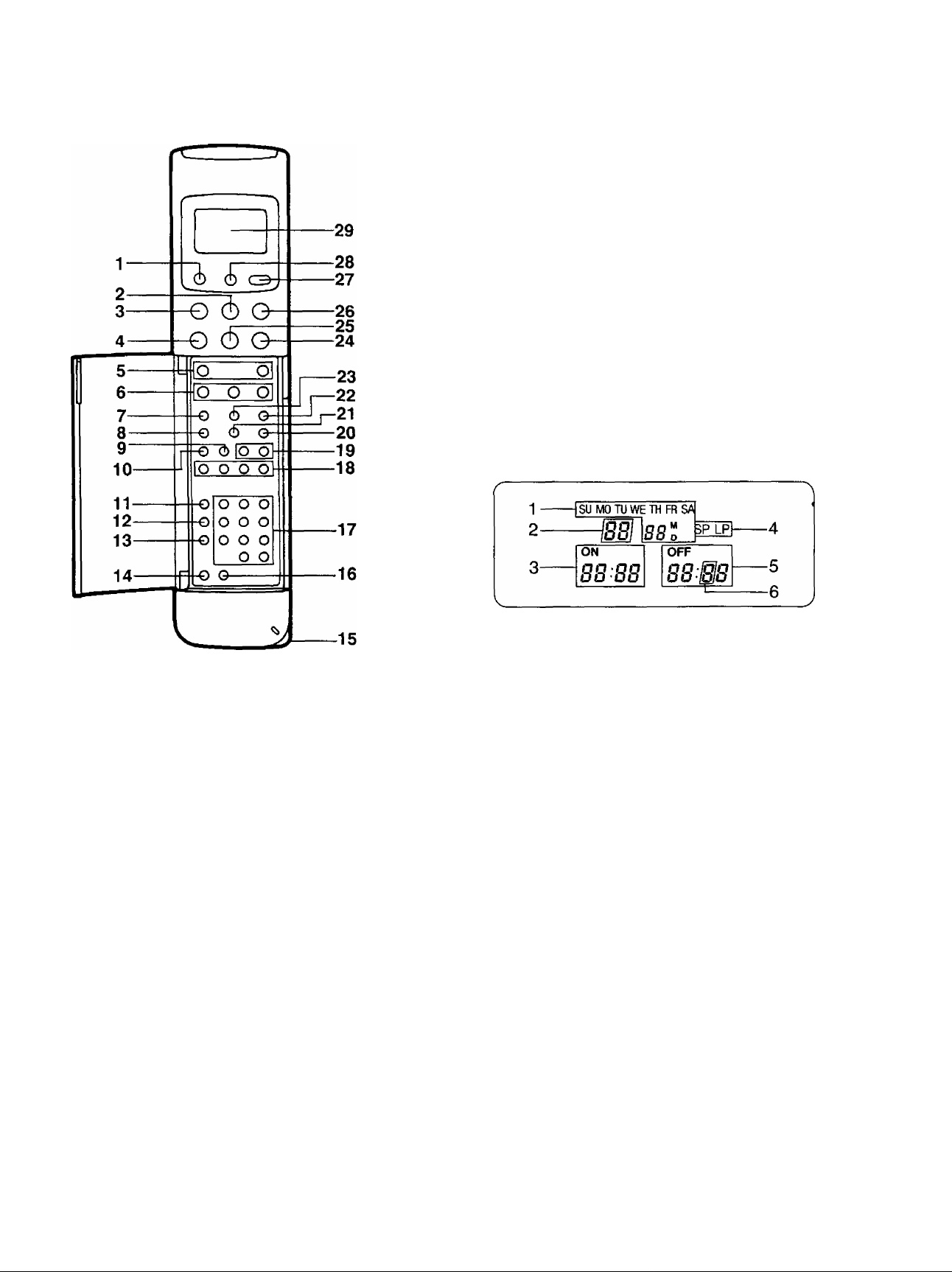
¡nfra-Red Remote Controller
1 VTR On/Off Button
2 Stop Button (■)
3 Pause/Still Button (I I)
4 Rewind ◄◄/Review @ Button
5 Record Buttons
6 Slow Buttons
7 Clock/Counter Selector
8 Monitor Button
9 Time Search Button
10 Index Button
11 Programme Button
12 Next Button
13 Tape Speed Selector
14 Timer Record Button
15 Bar Code Reading Section
16 Clear Button
17 Programme Position (Channel) Selector Buttons
18 Auto Play Buttons
19 Tracking/V-Lock and Buttons
20 Input Signal Selector
21 VTR/TV Selector
22 Reset Button
23 Tape Remain Button
24 Fast Forward ►►/Cue @ Button
25 Play Button (►)
26 Still Advance Button (ll^)
27 Transmit Button
28 Digital Scanner On/Off Button
29 Display
1 Date Display
2 Channel Display
3 Start Time Display
4 Tape Speed Indicator
5 End Time Display
6 Check Indicator
Power Source for the Remote Controller
■ The Remote Controller is powered by 2 I EC ‘‘R6" size
batteries. The life of the batteries is about one year,
however, it depends on the frequency of use. inspect and
if necessary, replace the batteries once a year,
CAUTION FOR BATTERY REPLACEMENT
• Load the new batteries with their polarities (0 and 0)
aligned correctly.
• Do not apply heat to batteries, or internal short-circuit
may occur.
• If you do not intend to use the Remote Controller for a
long period of time, remove the batteries and store them
in a cool and dry place.
• Remove spent batteries immediately and dispose of
them.
• Do not use an old and a new batteries together. (Also
never use an alkaline battery with a manganese battery.)
(6)
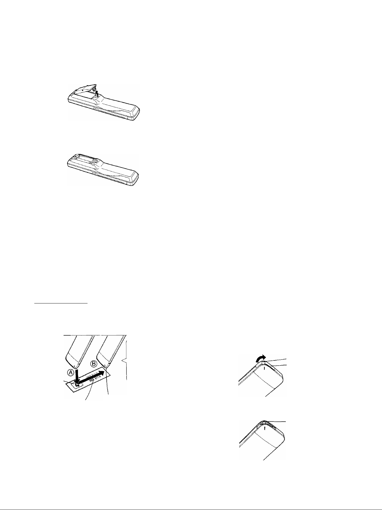
Infra-Red Remote Controller (Cont’d)
Load the batteries as follows:
1 Remove the battery compartment lid.
2 Place the batteries in the battery compartment as
indicated inside the battery compartment.
3 Replace the lid.
How to Operate the Remote Controller
(Digital Scanner)
Press the Digital Scanner On/Off Button to “ON”.
• If no operation is performed for more than 25 seconds
(4 minutes during setting of the clock time), the scanner
will automatically switch over to the power-saving
standby condition and the lamp will go off. (In this case, if
bar codes have already been read but not yet
transmitted to the VTR, the data will be cancelled.)
• When the lamp is not lit, press the button to turn it “ON”
again.
Tracing the Bar Codes
____________________________
(A) Place the Remote Controller on the Small Box,
(B) Trace the bar code quickly in the direction of the
arrow.
Small Box
Bar Code
The “Beep”
sound indicates
that the barcode
was read
completely.
Trace the bar code
completely past the last bar.
Note:
The bar codes “VTR 1 ” and “VTR 2" in the column
“REMOTE MODE” on the Programming Sheet cannot be
used with this unit.
•If the bar code “VTR 2” is traced by mistake, transmission
to the VTR becomes impossible. To remedy this
condition, trace the “VTR 1" bar code. (The indication
“VTR 2” in the Display will disappear.)
• Treat the Programming Sheet with care. If the
sheet gets dirty or scratched, the bar code reading
may become impossible.
• Protect the Remote Controller from strong shocks
and vibration. Keep it away from water and places
with high temperature and humidity.
• If the bar code is traced slowly, it cannot be read
correctly.
• When there is no “Beep” sound, the reading of the
bar code is incomplete. Trace the bar code again.
• When using the Programming Sheet, put it on flat
surface: Reading the bar codes while holding it In
your hand or bending it, may result in incorrect
operation.
• Do not deviate from the bar code, nor stop tracing
halfway.
V______________________________________/
Note:
• The infra-red beam should be transmitted directly at the
Infra-red Remote Control Receiver on the front of the
VTR.
• Direct sunlight may interfere with the beam,
• The lightsensing angle of the Infra-red Remote Control
Receiver In the VTR Is about 30° for each side from the
centre.
•The unit should be used within a range of about 7 meters
from the front of the VTR,
Recommendation
After the programming of timer recording(s) is completed,
press the Digital Scanner On/Off Button so that the
indications in the Display disappear, in order to save
battery power.
When the Bar Codes Cannot be Read
Although the lamp in the tip of the Bar Code Reading
Section lights up:
• No figures appear in the Display
• No beep sounds is heard;
The tip of the Bar Code Reading Section is probably
clogged with dirt.
Cleaning
1 Remove the cap of the Bar Code Reading Section.
• Remove dirt and dust from the hole of the cap.
Hole
Cap
Gently wipe the tip of the lamp with a soft cloth.
• Reattach the cap by inserting it until it locks with a
click.
Lamp
<7>
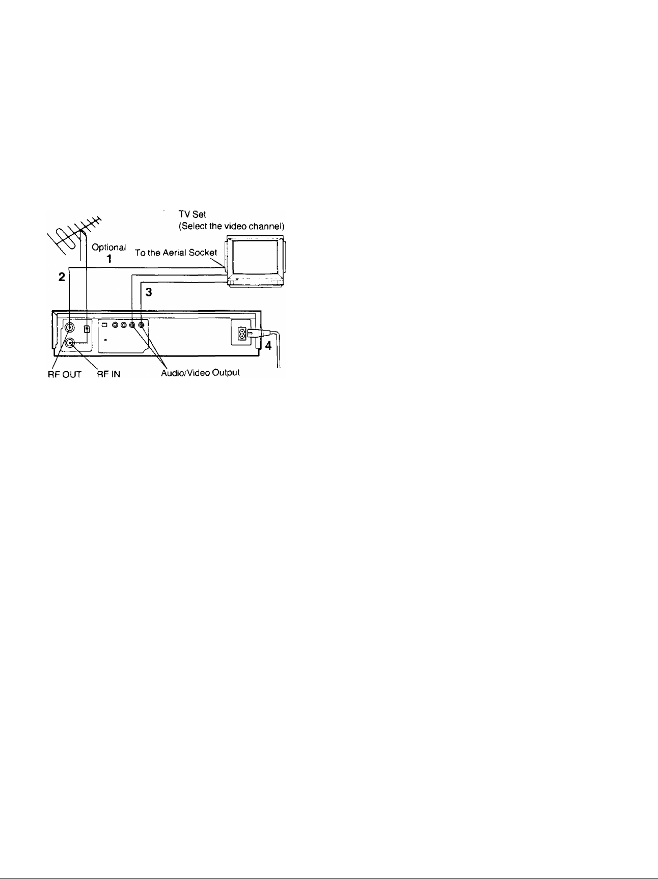
Installation
Connection to a TV Set
NV-J45A:
FOR YOUR SAFETY
Install any external aerial to AS 1417.1.
1 Connect the external aerial to the RF Input Socket on
the VTR.
2 Connect the aerial terminal on your TV set to the RF
Output Socket on the VTR with the supplied DIN-DIN
Coaxial Cable.
3 If the TV set is equipped with separate video and
audio input sockets, it is recommended to connect the
VTR to the TV set with separate video and audio
cables (not supplied).
4 Connect the AC Mains Lead to the AC Mains Socket
of the VTR to the mains outlet.
(8)
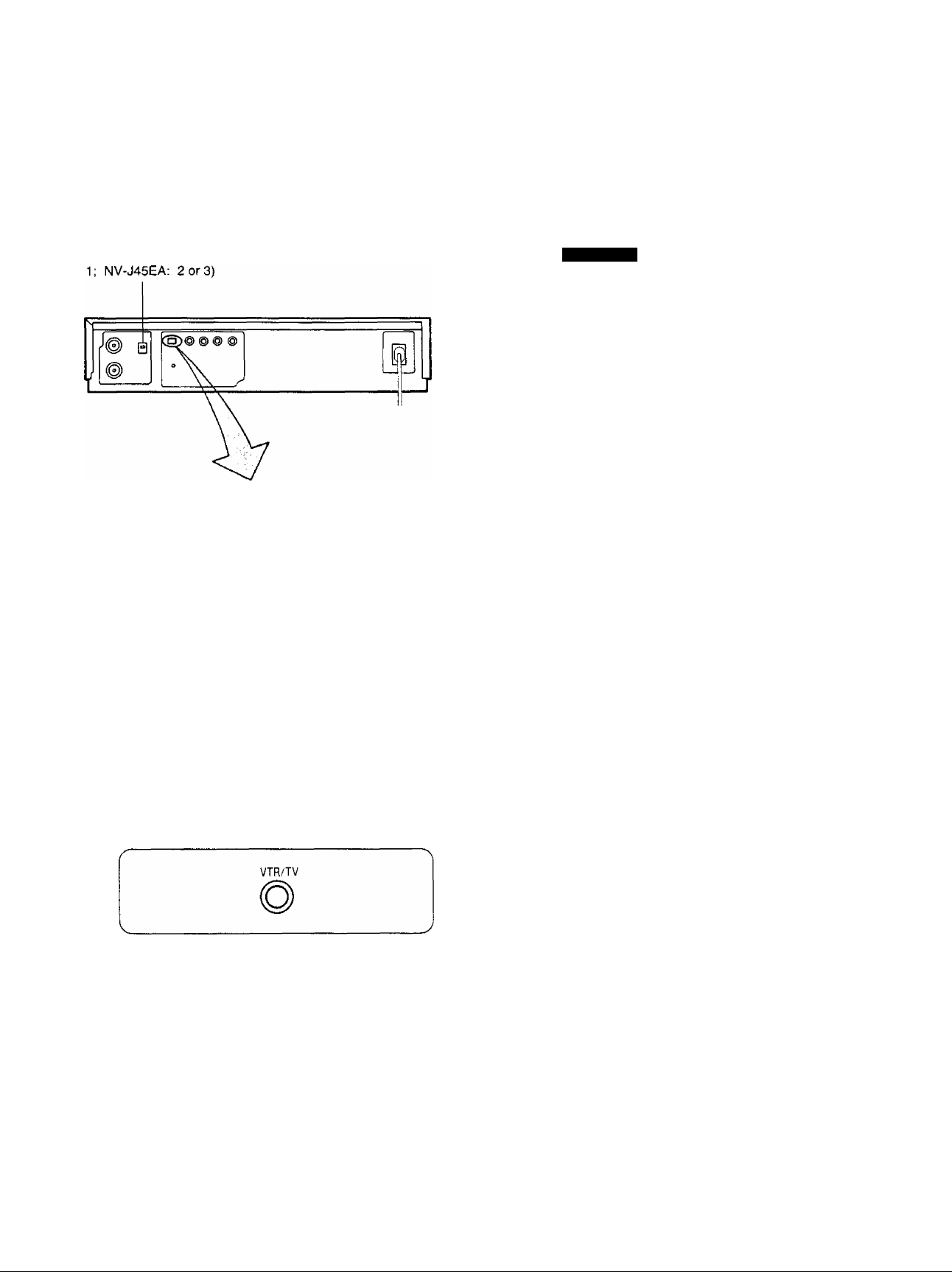
Tuning the TV Set to the Video Playback Channel
The adjustments described on this page are not
necessary, if the VTR is connected to the TV set via the
Video/Audio output sockets.
Video Playback Channel Selector
This switch is used to select the video playback channel
which is not occupied with any TV station.(NV-J45A: 0 or
□
OFF ON
TEST
SIGNAL
Tune your TV to VHF channel as shown below.
Confirm by your TV that the received test pattern is as
shown below.
NV-J45A: VHF channel 0 or 1*
NV-J45EA; VHF channel 2 or 3
NV-J45A only
*ln some areas
channel 0 may be
used by focal TV
station. In this case
switch to channel 1.
6 Set the Test Signal Switch to "OfT. Your TV is now
ready to receive the RF output signal from the VTR.
□
OFF ON
TEST
SIGNAL
7 To check, playback a pre-recorded tape and comfirm
that the picture quality is satisfactory.
1 Turn the TV set on and select the AV programme
position or another programme position that is not
occupied by any TV station.
2 Press the VTR On/Off Switch to turn the VTR On.
(FRONT SIDE)
o
VTR
• The corresponding indicator lights up.
3 Press the VTR/TV Selector to "VTR” position.
VTR Indicator will appear in the Multi-Function
Display.
4 Set the Test Signal Switch to "On”.
□
OFF ON
TEST
SK3NAL
<9)
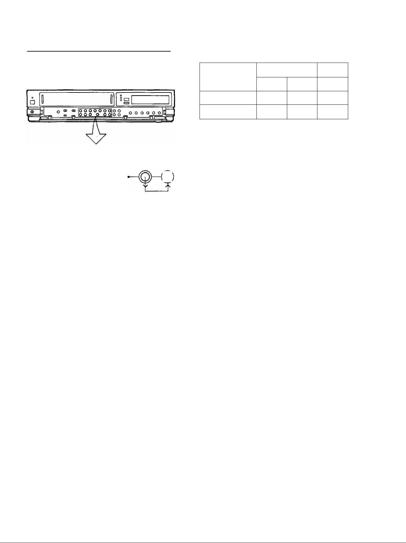
Setting the Tuner in the VTR
The tuner in the VTR makes it possible to receive TV
broadcasts and to record these programmes without
having to turn on the TV set.
CLOCK PROG/
RECORDING TRACKING/V-LOCK TIMER REC VTR/TV
©—©° (Q)
PRESET/ 1
_____________
_
T- jTL
©—© ©“"^
FINE/MORMAL B/ND/AFC CLEAR
NE
3-2
XT
D
4-2
1-5
1-3
Preparation
• Turn the TV set on and select the programme position
(channel) which you have tuned to the video playback
channel.
• Press the VTR On/Off Switch to turn the VTR on.
• Set the VTR/TV Selector to “VTR”.
PRE-PROGRAMMED TV CHANNELS (NV-J45A)
The local TV transmission channels 2, 7, 9 and 10
are factory-preset in this VTR. That is, if you can
receive television broadcasts on VHP channels 2, 7,
9 and 10, these are already tuned on the
programme positions with the matching numbers.
However, it is possible to cancel these presettings
and tune the local TV broadcast channels on any
desired programme positions.
For alternative settings and tuning of additional TV
broadcasts channels, follow the Tuning Procedure
below.
Tuning Procedure
1 Press the Preset/Fine/Normal Button on the VTR.
The indication on the Multi-Function Display changes
from the clock indication to the position indication.
2 Press the Channel Up or Down Button to select a
programme position (channel) which you want to tune
to a TV station.
3 Press the Band/AFC Button to select the “I”, “III” or
“U" position.
Display of the programme
positions 1-99
Indication of the
selected TV band
VHF
UHF
1
III
U
NV-J45A
0-5
5A-11
21-69
NV-J45EA
1-3
4-11
21-69
The tuner in the VTR can be preset with up to 99 stations.
4 Press the “-f” or Button until the picture of the
desired station on your TV is satisfactory.
• If the or Button is pressed while pressing
the Next Button, the stations will change quickly.
: Po
During the station search
(The position indication
flashes on and off.)
Tuned condition
• The tuned station is automatically memorized.
Repeat steps 2-4 for each channel you want to tune to a
station.
5 Press the Preset/Fine/Normal Button twice.
The indication on the Multi-Function Display changes
back to the previous indication.
Fine Tuning Procedure
If fine tuning is necessary, for example for a weak station
which is close to a strong station:
1 Press the Preset/Fine/Normal Button twice.
2 Press the “-f” or Button to obtain the best tuning
condition.
• “AFC” Indicator will not be displayed.
• To return the tuning to its former state, press the
Band/AFC Button.
3 Press the Preset/Fine/Normal Button.
<10>
Setting the Tuner in the VTR (Cont’d)
CLOCK PROG/
RECORDING TRACKING/V-LOCK TIMER REG VTR/TV
Oh©-s@-@ ©-©•©
PRESET/ t
_____________
a _ 1
FINE/NORMAL BAND/AFC CUAR
NEXT
1*4
1-3
3-2
2.2
Blanking of Unoccupied Programme Position
\t\onsf~S’jC'f7n<}Je
1 Press the Preset/Fine/Norma! Button.
2 Press the Channel Up or Down Button to select a
programme position (channel) which you do not want
to tune to a TV station.
3 Press the Clear Button (“—” will be displayed in the
Programme Position Indication).
^
• Repeat steps 2 and 3 for any programme positions
on which no stations are to be tuned. Afterwards,
these programme positions will be skipped during
Up/Down selection of the programme position.
4 Press the Preset/Fine/Normal Button twice.
Cancelling the Clear Function (Blanking)
1 Press the Preset/Fine/Normal Button.
2 To cancel the blanking of a programme position,
select that programme position on the VTR and then
press the Clear Button.
3 Press the Preset/Fine/Normal Button twice.
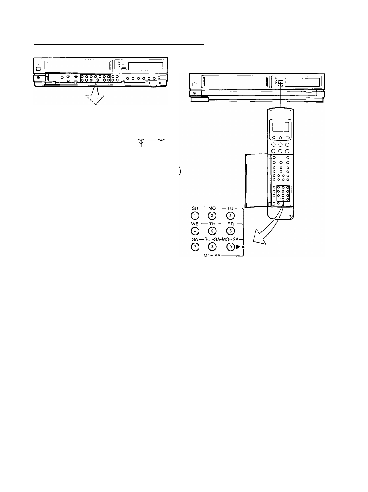
How to Select the Programme Position (Channel) on
the Remote Controller
©
0
select channel
press button
1-9
respective channel
10
©-►©-►0
20
©_►©_»©
11-99
for example 32
©_► 0-»0
If more than 5 seconds pass between the first, second and
third push, the channel will not be changed normally.
To select the “A1" programme position;
Press the Input Signal Selector.
To select the signals which are input via Audio Input
Socket and Video Input Socket, select the “A1 ’’
programme position.
(11)
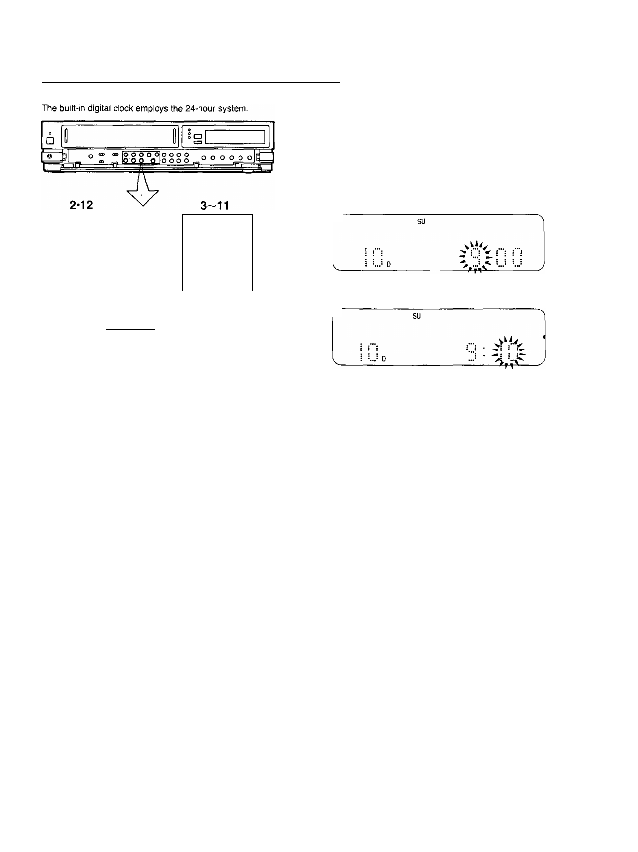
Setting the Clock to the Present Time
CLOCK PROG/Baaa RECORDING
TRACKING/V-LOCK
OhOH©-
PRFSFT/ 1
O ©
©—©—0-
FINE/NORMAL BA’ND/AFC CLEAR
NEXT
For Example: Set the clock for Sunday, October 10,
___________
1999, 9:10.
___________________
• Connect the VTR to the mains outlet.
• Press the VTR On/Off Switch to turn the VTR On.
1 When connecting this VTR to the mains or after a
long power failure, the indications flash.
i i • : ; ! s ^
2 Press the Clock Button to start the date and time
setting.
SA
> t I : : r-
3 Press the or Button to set the year.
FR
^ z : :
4 Press the Next Button.
5 Press the "+” orButton to set the month.
FR
-! !
7 Press the or Button to set the date.
^ su
^ i i i ^ ; I ■ J J
__
__ ____ _ ____ _ ____ _ ____
!£
8 Press the Next Button,
9 Press the “+” or Button to set the hour.
r
10 Press the Next Button.
11 Press the “+” or Button to set the minute.
r
12 Press the Clock Button when the present time
becomes exactly 9:10'00".
su
:
At every push of the Next Button, the flashing indication
changes in the following order.
YEAR^MONTH^DATE^HOUR-^MINUTE
• In case of a power failure, the timer back-up
system maintains the clock operation and timer
content for at least 60 minutes. However,
depending on the charging time and the memory
content, the back-up time may be considerably
longer. However, it takes more than 60 minutes for
the back-up circuit to become operational, after the
VTR is connected to the mains.
•The Timer Record Function should be set to “Off”,
otherwise the VTR cannot be operated normally. In
this case, the Timer Record Indicator “Hi” will flash
to warn you.
• During date setting, the corresponding day is
simultaneously set.
• The clock/timer of the VTR is programmed with the
calendar up to the end of the year 2087.
The indications 88-99 are for the years 1988-1999.
The indications 00-87 are for the years 2000-2087.
6 Press the Next Button.
(12)
Setting the Clock to the Present Time (Cont’d)
Setting the Clock to the Present Time Using the Bar
Codes
itttt
1
B--------------------
__
_
X til
II
.<: m
rr III
« 4111
i'i t'W
lili
:'i mi
h ilil
I un
X INI
Mil
<! im
lili
'1 ilil
>: ili|
•1 lili
1i lili
- IIH
■! lili Xi lili
• lili
■ «II a iiii
lili 'X lili
i'i 111
r lili
« III
U. Ill
l> lili
xi m
l"i lili
-1 «III
xj illl
lili
«1 illl
h IlU
< lili
111 X. lili
x lili
M
i
M' ihl
X lili
Xi Ull
X tlll
x^ lili
X: IlU
a iti
r ilU
: Jiti
m
Ull
tur
; iiiih
IM M
Ifl
it w
Preparation
• Press the Digital Scanner On/Off Button to turn it “ON”.
1
Trace the bar code “SETTING OF THE CLOCK”.
SETTING OF THE CLOCK
□-
2
Trace the bar code for the year (YEAR).
39
1IMQ-
3
Trace the bar code for the month (MONTH).
MONTH
m-m
4
Trace the bar code for the day of the month (DATE).
2 DATE
0MI»
5
Trace the bar code for the hour (START TIME).
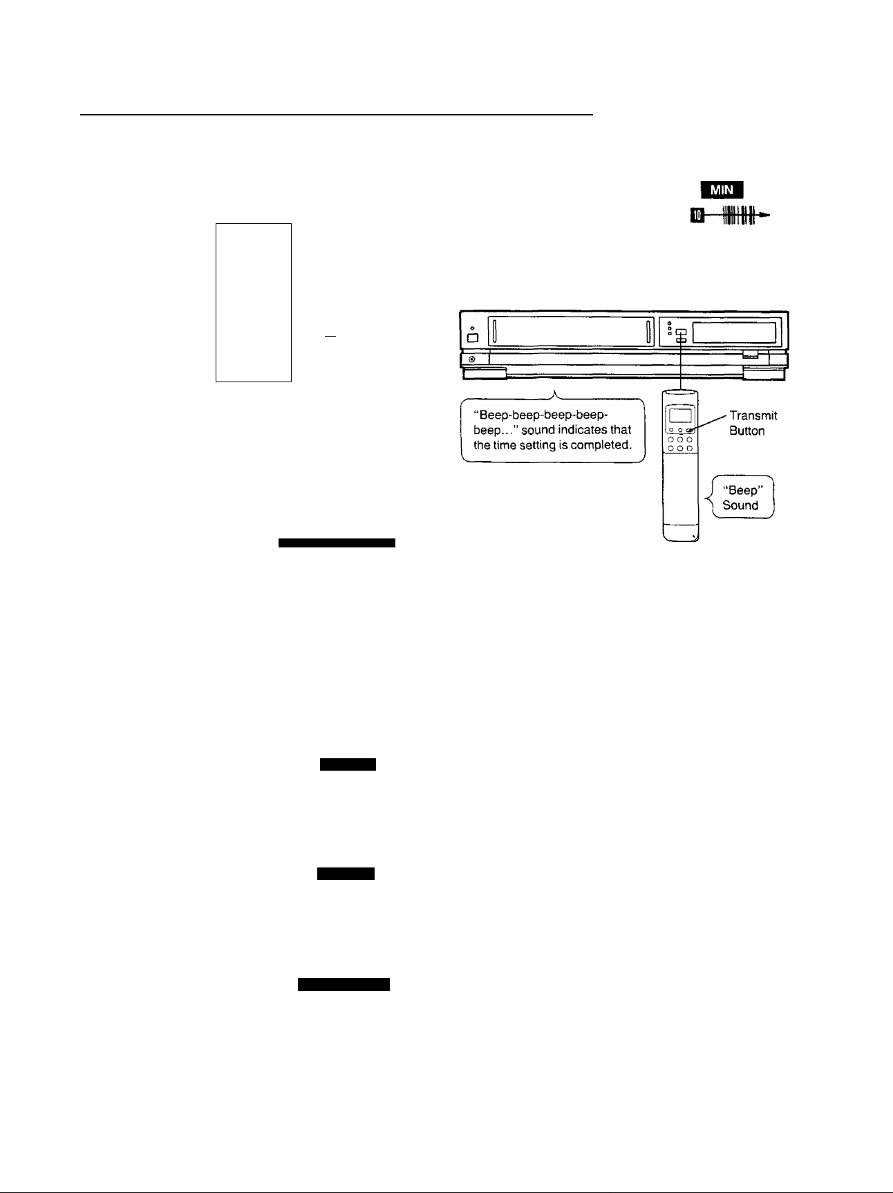
6 Trace the bar code for the minute (MIN).
5
. m
■ <(j
7
Press the Transmit Button (Remote Controller) and
then confirm that the time is displayed in the
Multi-Function Display of the VTR.
8 Press the Digital Scanner On/Off Button to turn it
“OFF”.
• if the transmission was not received correctly, the
“Beep-Beep, Beep-Beep” sound from the VTR will warn
you. In this case, perform transmission again.
• If the Remote Controller is left with no operation
performed for more than 4 minutes, it will automatically
switch over to the power-saving standby condition and
the lamp in the reading tip goes out. In this case, bar
codes that have already been read (but not yet
transmitted to the VTR) will be cancelled.
• The bar codes “SETTING OF THE CLOCK”, “YEAR”
and "MONTH” are located on page 3 of the
Programming Sheet.
3 START TIME
Q-nn 9
JUU •
(13)
Loading...