

Panasonic AG-DTL1 User Manual
Before attempting to connect, operate or adjust this product, please read these instructions completely.
Model AG- P
F0600W
@
Printed in Japan
VQT8822
P
Digital Time Lapse
Video Cassette Recorder
2
indicates safety information.
IMPORTANT
“Unauthorized recording of copyrighted
television programs, video tapes and other
materials may infringe the right of copyright
owners and be contrary to copyright laws.”
$
Do not insert fingers or any objects into the video
cassette holder.
$
Avoid operating or leaving the unit near strong magnetic
fields. Be especially careful of large audio speakers.
$
Avoid operating or storing the unit in an excessively hot,
cold, or damp environment as this may result in
damage both to the recorder and to the tape.
$
Do not spray any cleaner or wax directly on the unit.
$
If the unit is not going to be used for a length of time,
protect it from dirt and dust.
$
Do not leave a cassette in the recorder when not in use.
$
Do not block the ventilation slots of the unit.
$
Use this unit horizontally and do not place anything on
the top panel.
$
Cassette tape can be used only for one-side, one
direction recording. Two-way or two-track recordings
cannot be made.
$
Cassette tape can be used for either Color or Black &
White recording.
$
Do not attempt to disassemble the recorder.
There are no user serviceable parts inside.
$
If any liquid spills inside the recorder, have the recorder
examined for possible damage.
$
Refer any needed servicing to authorized service
personnel.
CAUTION
RISK OF ELECTRIC SHOCK
DO NOT OPEN
CAUTION: TO REDUCE THE RISK OF ELECTRIC SHOCK,
DO NOT REMOVE COVER (OR BACK).
NO USER SERVICEABLE PARTS INSIDE.
REFER TO SERVICING TO QUALIFIED SERVICE PERSONNEL.
The lightning flash with arrowhead symbol,
within an equilateral triangle, is intended to
alert the user to the presence of uninsulated
“dangerous voltage” within the product’s
enclosure that may be of sufficient magnitude
to constitute a risk of electric shock to persons.
The exclamation point within an equilateral
triangle is intended to alert the user to the
presence of important operating and
maintenance (service) instructions in the
literature accompanying the appliance.
CAUTION:
Do not install or place this unit in a bookcase,
built-in cabinet or in another confined space
in order to keep well ventilated condition.
Ensure that curtains and any other materials
do not obstruct the ventilation condition to
prevent risk of electric shock or fire hazard
due to overheating.
WARNING:
TO REDUCE THE RISK OF FIRE OR SHOCK
HAZARD, DO NOT EXPOSE THIS EQUIPMENT
TO RAIN OR MOISTURE.
CAUTION:
TO REDUCE THE RISK OF FIRE OR SHOCK
HAZARD AND ANNOYING INTERFERENCE,
USE THE RECOMMENDED ACCESSORIES
ONLY.
FCC Note:
This device complies with Part 15 of the FCC Rules.
To assure continued compliance follow the attached
installation instructions and do not make any
unauthorized modifications.
This equipment has been tested and found to comply
with the limits for a class A digital device, pursuant to
Part 15 of the FCC Rules. These limits are designed to
provide reasonable protection against harmful
interference when the equipment is operated in a
commercial environment. This equipment generates,
uses, and can radiate radio frequency energy and, if
not installed and used in accordance with the
instruction manual, may cause harmful interference to
radio communications. Operation of this equipment in a
residential area is likely to cause harmful interference
in which case the user will be required to correct the
interference at his own expense.
Replace battery with part No. VL3032/1GUF only.
Use of another battery may present a risk of fire or
explosion.
Caution—Battery may explode if mistreated.
Do not recharge, disassemble or dispose of in fire.

3
Contents
Features . . . . . . . . . . . . . . . . . . . . . . . . . . .4
Parts and their functions . . . . . . . . . . . . .5
Front panel . . . . . . . . . . . . . . . . . . . . . . . . . . . . . .5
Rear panel . . . . . . . . . . . . . . . . . . . . . . . . . . . . . .10
Performing initial settings . . . . . . . . . . .11
Setting the date and time . . . . . . . . . . . . . . . . . . .11
Simple time adjustment . . . . . . . . . . . . . . . . . . . .12
Simple date and time adjustment . . . . . . . . . . . .13
Setting the recording time mode and number of
cameras . . . . . . . . . . . . . . . . . . . . . . . . . . . . . . . .14
Setting the recording mode . . . . . . . . . . . . . . . . .15
Frame recording and field recording . . .17
Connections . . . . . . . . . . . . . . . . . . . . . . .18
Recording . . . . . . . . . . . . . . . . . . . . . . . . .20
Playback . . . . . . . . . . . . . . . . . . . . . . . . . .21
Normal playback . . . . . . . . . . . . . . . . . . . . . . . . .21
Still-picture playback . . . . . . . . . . . . . . . . . . . . . .21
Changing over the screen display . . . . .22
Changing over the screen during playback . . . . .22
Changing between the 1-screen and 4-in-1 screen
display . . . . . . . . . . . . . . . . . . . . . . . . . . . . . . . . .22
Switching between the cameras . . . . . . . . . . . . .22
Useful functions . . . . . . . . . . . . . . . . . . .23
Memory stop . . . . . . . . . . . . . . . . . . . . . . . . . . . .23
Alarm recording and sensor (emergency)
recording . . . . . . . . . . . . . . . . . . . . . . . . . . . . . . .24
Alarm memory recall and power loss memory
recall . . . . . . . . . . . . . . . . . . . . . . . . . . . . . . . . . .26
Search playback (cue/review) . . . . . . . . . . . . . . .27
Alarm search (alarm recording section search) . .27
Time/date search . . . . . . . . . . . . . . . . . . . . . . . . .28
Internal timer recording . . . . . . . . . . . . . . . . . . . .29
External timer recording . . . . . . . . . . . . . . . . . . .33
Terminal connections . . . . . . . . . . . . . . .35
Alarm recording connections . . . . . . . . . . . . . . . .35
Tape-end output connections . . . . . . . . . . . . . . .36
Auto OFF output connections and recording output
connections . . . . . . . . . . . . . . . . . . . . . . . . . . . . .36
External timer input connections . . . . . . . . . . . . .36
Time setting connections . . . . . . . . . . . . . . . . . . .37
External timer input connections . . . . . . . . . . . . .37
Terminal signal levels . . . . . . . . . . . . . . .38
Setting menus . . . . . . . . . . . . . . . . . . . . .39
Setting method . . . . . . . . . . . . . . . . . . . . . . . . . .39
Menu page P1
TIME/DATE PRESET screen . . . . . . . . . . . . . . .40
REC LOCK screen . . . . . . . . . . . . . . . . . . . . . . .40
HOUR METER screen . . . . . . . . . . . . . . . . . . . . .40
Menu page P2
DISPLAY screen . . . . . . . . . . . . . . . . . . . . . . . . .41
REC LOSS INDICATOR screen . . . . . . . . . . . . .41
DAYLIGHT SAVING screen . . . . . . . . . . . . . . . .42
Menu page P3
RECORDING T-MODE & CAMERA screen . . . .43
Menu page P4
RECORDING MODE screen . . . . . . . . . . . . . . . .43
ALARM/SENSOR REC screen . . . . . . . . . . . . . .44
Menu page P5
VTR MODE SELECT screen . . . . . . . . . . . . . . . .45
Menu page P6
TAPE REMAIN screen . . . . . . . . . . . . . . . . . . . .46
REC REVIEW screen . . . . . . . . . . . . . . . . . . . . .46
ERROR WARN BUZZER screen . . . . . . . . . . . .47
REC WARNING screen . . . . . . . . . . . . . . . . . . . .47
Menu page P7
TERMINAL INPUT SELECT screen . . . . . . . . . .48
TERMINAL OUTPUT SELECT screen . . . . . . . .48
VIDEO OUT SEQUENCE screen . . . . . . . . . . . .49
EXT SWITCHER screen . . . . . . . . . . . . . . . . . . .49
Menu page P8
PROGRAM TIMER screen . . . . . . . . . . . . . . . . .50
INTERNAL WEEKLY TIMER screen . . . . . . . . . .50
Menu page P9
FREE SET TIMER screen . . . . . . . . . . . . . . . . . .51
Menu page P10
RS-232C PARAMETERS screen . . . . . . . . . . . .52
USER ID REC screen . . . . . . . . . . . . . . . . . . . . .52
RS-232C interface . . . . . . . . . . . . . . . . . .53
1. Hardware specifications . . . . . . . . . . . . . . . . .53
(1) Interface specifications . . . . . . . . . . . . . . .53
(2) Communication parameters . . . . . . . . . . .53
2. Software specifications . . . . . . . . . . . . . . . . . .54
(1) External interface specifications . . . . . . . .54
(2) Transmitting format (PC 5unit) . . . . . . . .54
(3) Receiving format (unit 5PC) . . . . . . . . . .55
(4) List of commands . . . . . . . . . . . . . . . . . . .56
Error messages . . . . . . . . . . . . . . . . . . .102
Video head cleaning . . . . . . . . . . . . . . .103
Condensation . . . . . . . . . . . . . . . . . . . .103
Maintenance . . . . . . . . . . . . . . . . . . . . . .103
Specifications . . . . . . . . . . . . . . . . . . . .104

4
Features
Built-in frame switcher for supporting 16 cameras
O
The unit also supports asynchronous cameras.
O
The unit enables recording after the cameras are
switched over automatically as dictated by the
recording time mode.
O
During recording, the cameras can be switched and
their images viewed on a TV monitor at a time other
than the recording timing which has been set.
Digital recordings with a high picture quality
Digital recordings with a high picture quality can be
made on S-VHS tapes. The incorporation of highperformance A/D and D/A circuitry means that highquality digital recording is possible even when
recording after switching from one camera to another.
O
High picture quality mode: 520 lines for horizontal
resolution, 50 dB for S/N ratio
O
Standard picture quality mode: 380 lines for
horizontal resolution, 50 dB for S/N ratio
Wide selection of recording time modes
O
There is a choice of 14 different recording time
modes.
O
It is possible to switch between frame recording and
field recording.
Camera-specific playback
During playback, any camera can be selected and its
recording played back. During cue or review, as well,
any camera can be selected and its recording played
back.
Playback with 4 pictures simultaneously shown
on the screen
The pictures recorded by four of the cameras can be
selected and, by dividing the TV monitor screen into
four parts, all of the four pictures can be played back
at the same time on the respective parts of the
screen.
Date/time search function
The recording date and time (month / day / hours /
minutes) can be selected to initiate a search of the
recorded data.
Alarm search function
Recorded data that includes alarm recordings can be
searched.
3 hours, 9 hours, 12 hours, 18 hours, 24 hours, 48 hours, 72
hours, 96 hours, 120 hours, 180 hours, 240 hours, 360
hours, 480 hours and 960 hours
High reliability and high durability
O
IQ mechanism with top-notch reliability and
durability
O
Stable tape travel achieved using a 2DD reel motor
O
Automatic head cleaning function for cleaning the
head cylinder each time a tape is loaded
Space-saving design with 38 cm width and vertical
installation capability
The unit can be installed upright on its left-side panel
and secured using the special-purpose mounting
brackets (optional accessory STEN-B6730).
O
Do not install the unit upright on its right-side panel.
This may cause the unit to malfunction.
On-screen setting functions
The unit’s many and varied functions can be set on
the monitor screen.
Other features
O
75Ω termination ON/OFF function provided for
camera input (16) connectors
O
Switching between 8 camera input connectors and
8 camera loop-through outputs possible
O
RS-232C control facility
O
Audio recording (in the 3-hour to 24-hour time
modes)
O
Simple clock adjustment functions
O
Recording time and operating camera setting
function
O
Diverse internal timer and external timer functions
5
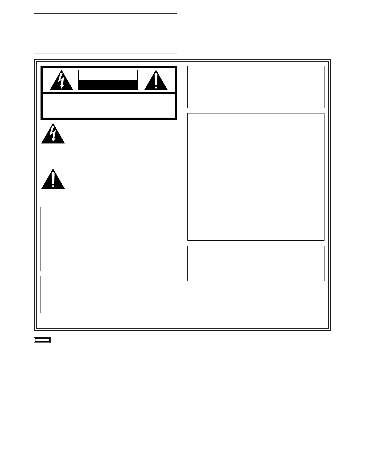
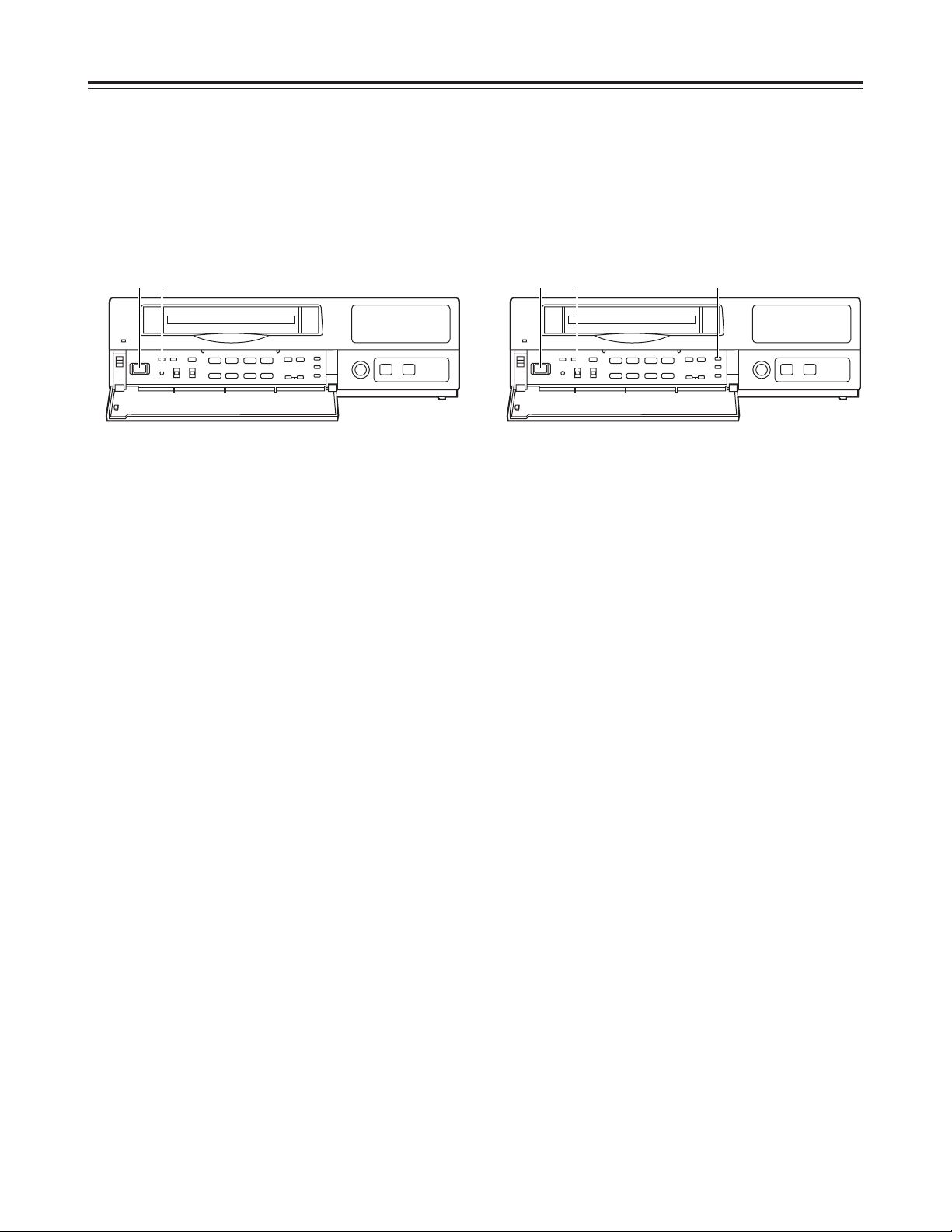
Parts and their functions
1
POWER lamp
This lights when the power is turned on.
2
Cassette insertion slot
Always use S-VHS cassette tapes. If a VHS tape is
inserted instead, it will be automatically ejected
when the REC button is pressed. A cassette tape
will also be ejected when the REC button is
pressed if its accidental erasure prevention tab has
been broken out.
3
EJECT button
Press this to eject the cassette tape.
It will not work unless it is pressed firmly.
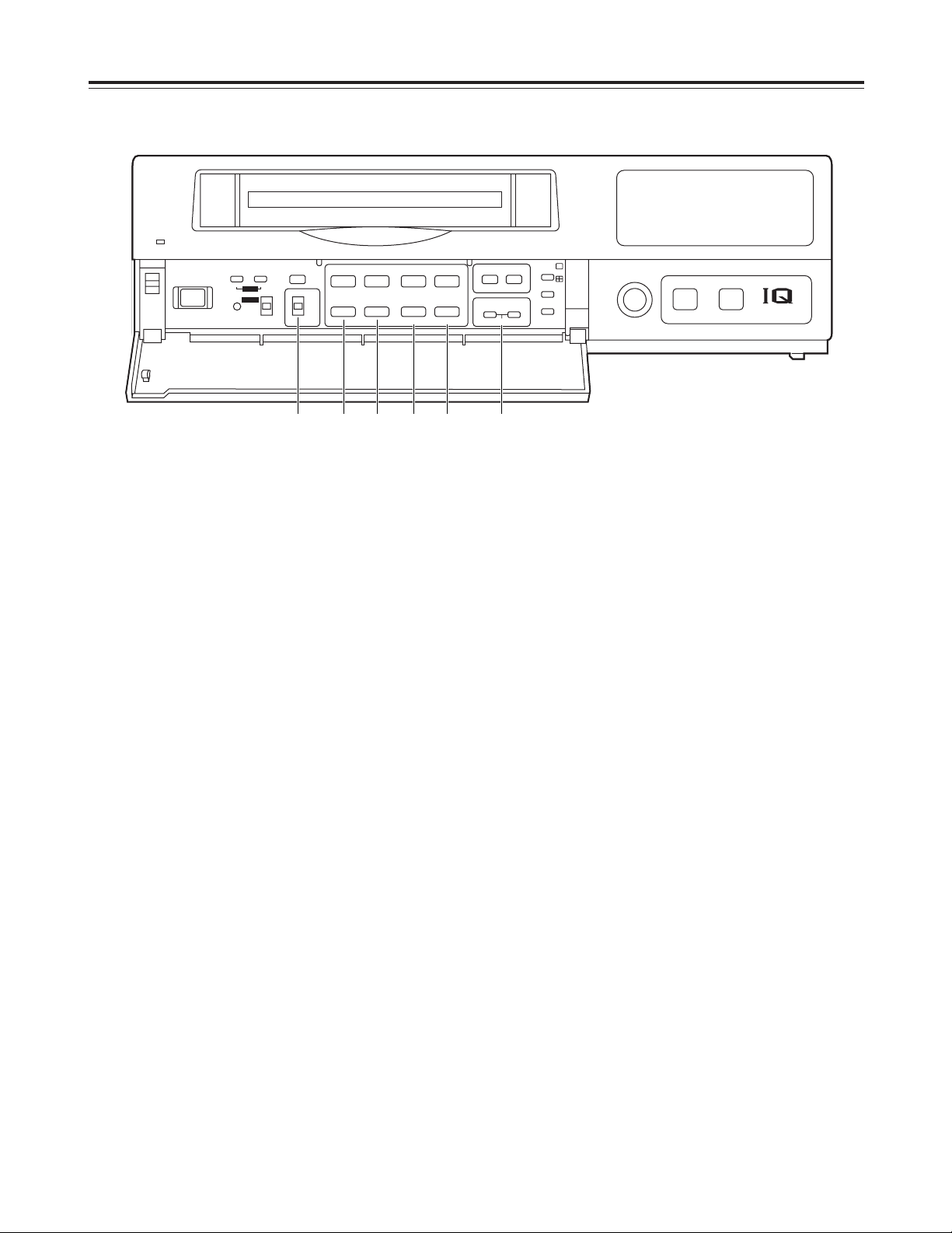
Front panel
4
REC REVIEW button
Press this during recording to monitor what is being
recorded. Several images captured a moment
before the button was pressed are played back,
and then the recording mode is restored.
It takes about 10 seconds for the playback picture
to appear.
5
REC button
Press this to start recording.
6
EJECT
REC
REVIEW
MECHANISM
¥REC
<
POWER
USE S-VHS CASSETTE TAPE ONLY
#PUSH-OPEN
1 2 43 5
M
AS
ALARM
REC
y
m
SUM TIME
COUNT
CAMERA
PASS
HIGH
FRAME
d
TIME
MODE
H
REMAIN
LOCK
EXT INT
172
8
56
12
11
9
43
10
9 = ?>
<; :
1
2
6
8
5
3
4
7
@
D
C
A
B
This unit is designed to provide the high level of
reliability required of a time lapse recorder for use
in such applications as surveillance, security and
monitoring.
In order to ensure that this unit will perform
reliably in recording operations, it is
recommended that the following Panasonic video
tape be used:
S-VHS tape: ST-120 series (120-minute tape)

6
Parts and their functions
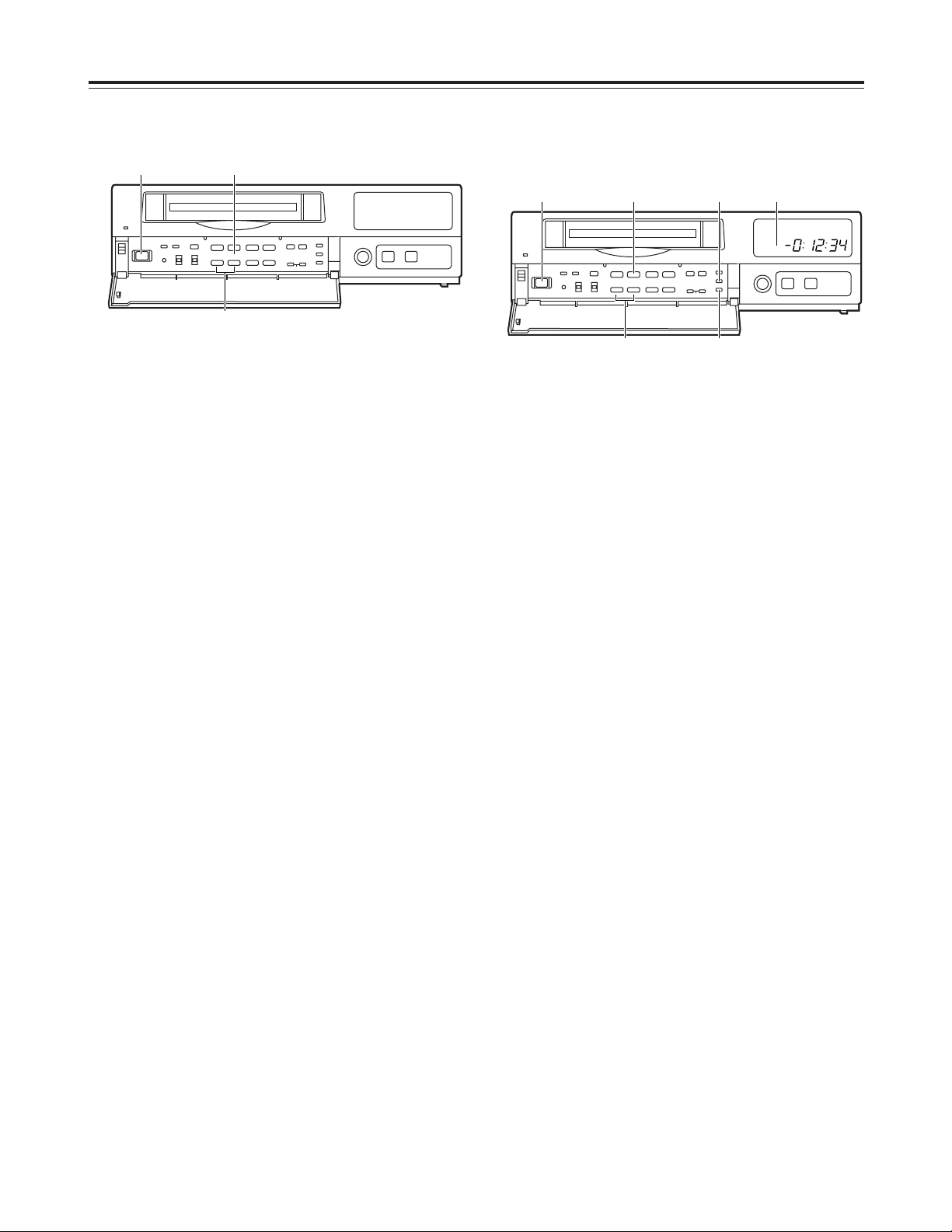
6
Display tube
1
=
Lights when a cassette tape is inserted.
It flashes when an error is detected as a result of
the recording review.
2
HIGH
Lights when a tape which was recorded in the
high picture quality mode is being played back
and when a tape is being recorded in the high
picture quality mode.
3
FRAME
Lights when a tape which was recorded in the
frame mode is being played back and when a
tape is being recorded in the frame mode.
4
SUM
Lights when the time is displayed in the summertime (daylight saving) mode.
5
TIME
Lights when the time is displayed.
6
COUNT
Lights when the tape counter value is displayed.
7
CAMERA
Lights when the camera number is displayed.
8
PASS
Lights when the number of repeated tape
recordings (passes) is displayed.
9
TIME MODE
Indicates the recording time mode.
:
Lights when repeat recording has been set.
;
M
Lights when the memory stop mode has been
set.
<
AS (S)
AS : Lights when the alarm search mode has
been set.
S:Lights when the time search mode has
been set. The lamp flashes while a search
is in progress.
=
ALARM
Lights during an alarm recording.
Flashes upon completion of the alarm recording.
>
REC
Lights during recording or rec-pause.
?
Video operation mode displays
: Playback
: Reverse playback
REC : Recording, recording monitoring
REC : Rec-pause
: Still picture (flashes during frame
playback), frame feed
: Fast forward, cue
: Rewind, review
@
REMAIN
Flashes when the tape end is approaching (when
the remaining tape alarm mode has been set).
A
LOCK
Lights when the lock mode has been set by the
LOCK switch or using the REC LOCK item on
the setting menu.
B
EXT
Lights when the external timer mode has been
set.
C
INT
Lights when the internal timer mode has been
set.
D
Counter display
Displays the time or tape counter value; displays
the error code when an error has occurred.
In addition, when a discrepancy has arisen
between the number of cameras set and the
number of cameras actually connected because
one of the cables connected to the CAMERA IN
connectors has been disconnected or loosened,
the camera number concerned will flash on the
display to warn the user.
7
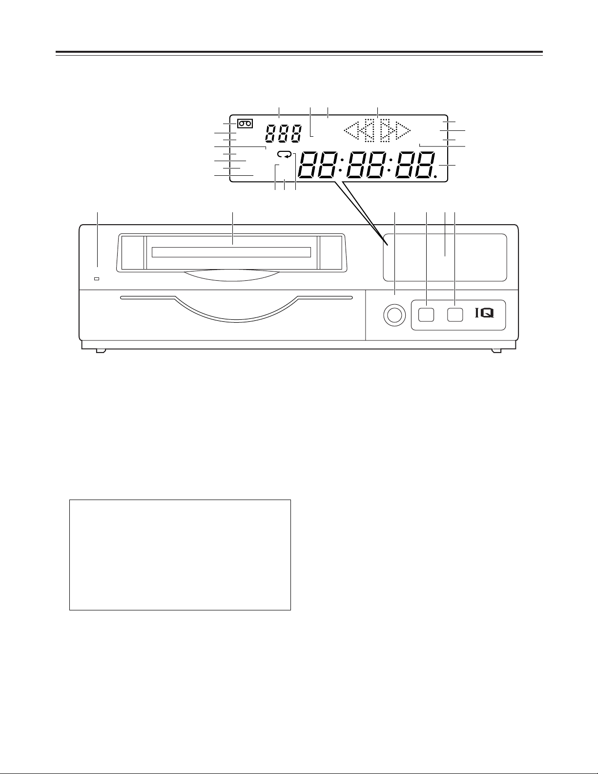
Parts and their functions
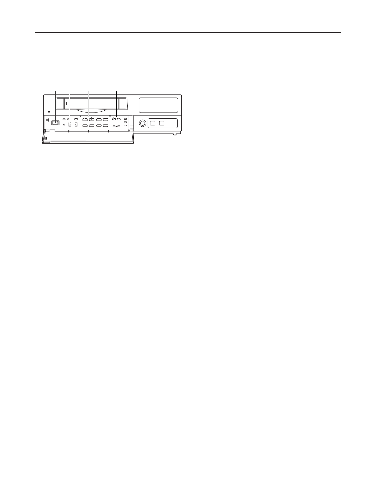
Front panel (sub panel)
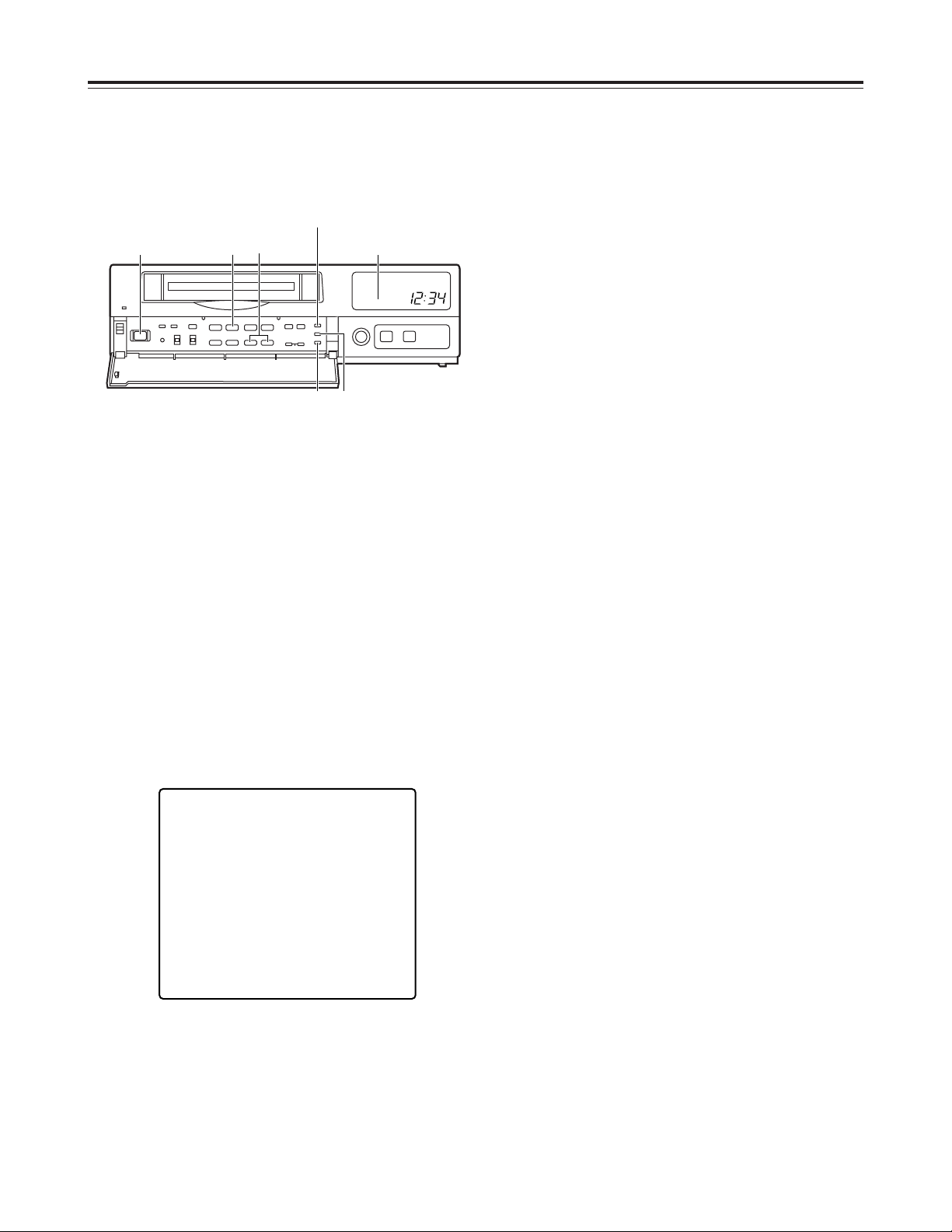
7
POWER switch
Used to turn the unit’s power ON and OFF.
When the power is turned on, the POWER lamp
lights, and the buzzer is sounded once.
8
TRACKING buttons
Press during normal playback to adjust the tracking.
When these buttons are pressed during still-picture
playback, the unit is set to the field still-picture or
frame still-picture mode.
However, the unit will not be set to the frame stillpicture mode if a tape recorded in the field mode
has been inserted.
9
TIMER MODE button
Used to select the timer mode. Each time it is
pressed, the mode is changed, and one of the
following mode lamps lights on the display tube.
No display: Normal recording
EXT : External timer recording
INT : Internal timer recording
:
REV PLAY button
Press to play back the tape in the reverse direction.
When the PROGRAM switch is at the MENU
position, this button functions as the PAGE (–)
button to select the setting menu screen.
When the PROGRAM switch is at the TIME ADJ
position, the button switches between the date
display and time display.
;
PLAY button
Press to play back the tape in the forward direction.
When the PROGRAM switch is at the MENU
position, this button functions as the PAGE (+)
button to select the setting menu screen.
When the PROGRAM switch is at the TIME ADJ
position, the button switches between the date
display and time display.
<
STOP button
Press to stop the operation mode.
When the PROGRAM switch is at the MENU
position, this button functions as the SHIFT (4)
button to select the items on the setting menu
screen.
When the PROGRAM switch is at the TIME ADJ
position, the button moves the screen display
position downward.
EJECT
REC
REVIEW
MECHANISM
¥REC
<
POWER
USE S-VHS CASSETTE TAPE ONLY
POWER
TRACKING
TIMER MODE
STILL
LOCK
REV PLAY PLAY STOP
SHIFT
SHIFTPAGE
PAUSE/STILL
TIME MODE
CAMERA
SEQUENCE
COUNTER
SEARCH
SET
REV AVD FWD AVD
REW
CB
FF
ALL
OFF
REC
MENU
OFF
:00
TIME
ADJ
FIELD FRAME
PROGRAM
21
21
65
∫;
34
34
3
4
34
H
H
ji
j i
j i
RESET
7 8 9 : ; < = > ? @ A
B C
8
Parts and their functions
=
PAUSE STILL button
Press to initiate rec-pause or still-picture playback.
When the unit remains in the pause or still-picture
playback mode for more than a prescribed period of
time, it is automatically set to the stop mode in
order to protect the tape.
When the PROGRAM switch is at the MENU
position, this button functions as the SHIFT (3)
button to select the items on the setting menu
screen.
When the PROGRAM switch is at the TIME ADJ
position, the button moves the screen display
position upward.
>
TIME MODE buttons
Press to select the recording time mode.
3H : 3-hour recording mode
9H : 9-hour recording mode
12H : 12-hour recording mode
18H : 18-hour recording mode
24H : 24-hour recording mode
48H : 48-hour recording mode
72H : 72-hour recording mode
96H : 96-hour recording mode
120H : 120-hour recording mode
180H : 180-hour recording mode
240H : 240-hour recording mode
360H : 360-hour recording mode
480H : 480-hour recording mode
960H : 960-hour recording mode
When the PROGRAM switch is at the MENU
position, these buttons function as the SET (+) and
(–) buttons to select the settings for the setting
menu items.
?
RESET button
Press while the counter value is shown on the
display tube by the COUNTER button to reset the
CTL counter.
When the camera number is shown on the display
tube by the COUNTER button during playback, this
button is used to switch the monitor screen
between 1-screen playback and 4-screen playback.
@
COUNTER button
Used to switch the display mode on the display
tube.
Each time the COUNTER button is pressed, the
mode is switched as follows.
Camera number display:
The current camera number is displayed.
CAMERA
172
8
56
12
11
9
43
10
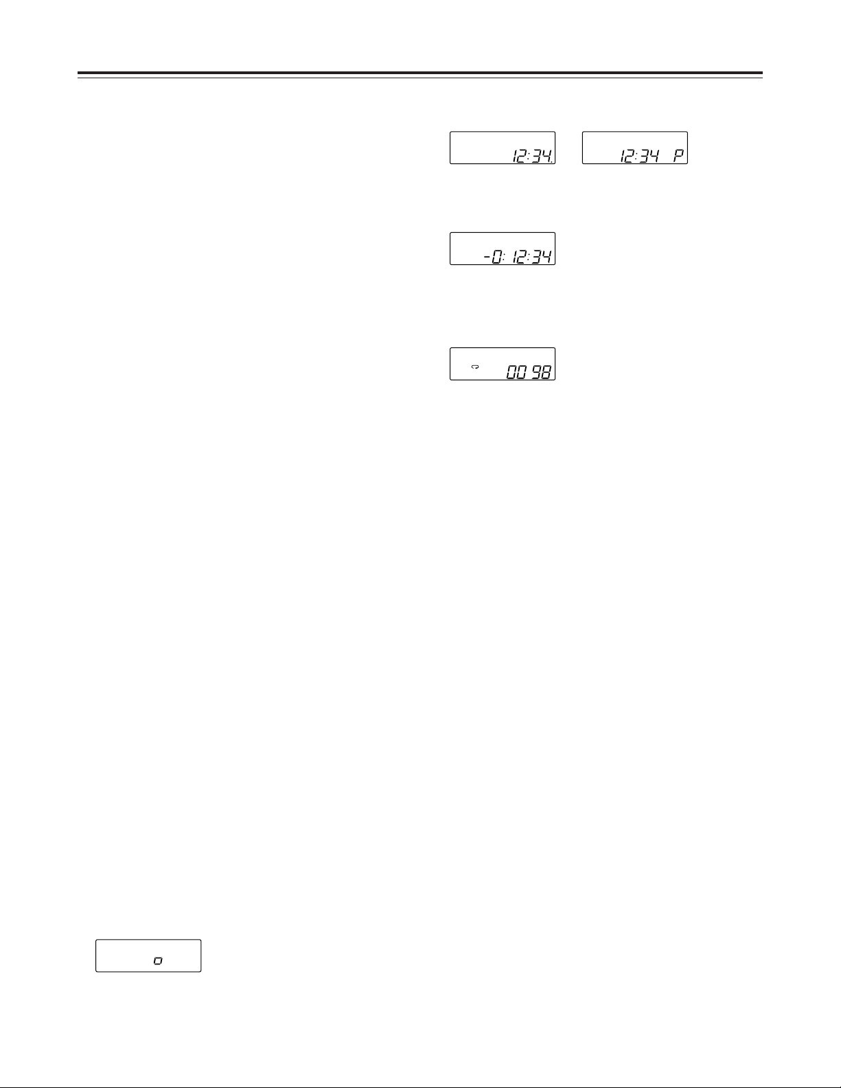
Clock display:
The current time is displayed.
24-hour display 12-hour display
Counter display:
The tape counter is displayed.
Pass display:
This indicates the number of times (passes) repeat
recording has been performed when repeat
recording has been set.
A
SEARCH button
Press to select the search mode.
Each time this button is pressed in the counter
display mode, the search mode is switched, and
one of the following mode lamps lights on the
display tube:
M:Memory stop mode
AS : Alarm search mode
When the SEARCH button is pressed while the
time is displayed on the display tube by the
COUNTER button, the time search mode is set,
and “S” lights on the display tube.
B
:00 button
Press to set the seconds digits of the time to “00.”
The seconds are reset to “00” when this button is
pressed while the display shows 0 to 29 seconds,
and they are carried up to 1 minute and set to “00”
when it is pressed while the display shows 30 to 59
seconds.
C
PROGRAM switch
Used to display the menu and adjust the time.
Keep this switch at OFF for normal operation.
MENU:
The setting menu screen is displayed.
When the switch is set to the MENU position
while holding down the STOP button, the alarm
screen or power loss screen appears.
TIME ADJ:
Set the switch to this position when adjusting the
time or adjusting the screen display position.
PASS
COUNT
TIME
TIME
9
Parts and their functions
H
FWD AVD button
Press during still-picture playback to advance the
tape frame by frame in the forward direction.
When the PROGRAM switch is at the MENU
position, this button serves as the SHIFT (1)
button to select the setting menu screen items.
When the PROGRAM switch is at the TIME ADJ
position, the button moves the screen display
position toward the right.
I
CAMERA buttons
In the playback mode:
Press during playback to select the camera and
play back the pictures recorded by the selected
camera.
In any other mode:
When the buttons are pressed in any other
mode, the camera to be monitored can be
selected.
When the [4] button and [3] button are pressed
together, the auto sequence mode is
established.
When they are pressed in the auto sequence
mode, the unit is switched to the manual
sequence mode.
Front panel (sub panel)
D
LOCK switch
Used to set the lock mode.
ALL : All normal operations are suspended, and
LOCK lights on the display tube.
OFF : Normal operations can be conducted.
REC : Normal operations are suspended after
recording has commenced, and LOCK lights
on the display tube.
(REC REVIEW button operations are
acknowledged.)
E
REW/Cbutton
Press in the stop mode to rewind the tape.
When this button is pressed during playback or stillpicture playback, the tape is reviewed.
F B
/FF button
Press in the stop mode to fast forward the tape.
When this button is pressed during playback or stillpicture playback, the tape is cued.
G
REV AVD button
Press during still-picture playback to advance the
tape frame by frame in the reverse direction.
When the PROGRAM switch is at the MENU
position, this button serves as the SHIFT (2)
button to select the setting menu screen items.
When the PROGRAM switch is at the TIME ADJ
position, the button moves the screen display
position toward the left.
EJECT
REC
REVIEW
MECHANISM
¥REC
<
POWER
USE S-VHS CASSETTE TAPE ONLY
POWER
TRACKING
TIMER MODE
STILL
LOCK
REV PLAY PLAY STOP
SHIFT
SHIFTPAGE
PAUSE/STILL
TIME MODE
CAMERA
SEQUENCE
COUNTER
SEARCH
SET
REV AVD FWD AVD
REW
CB
FF
ALL
OFF
REC
MENU
OFF
:00
TIME
ADJ
FIELD FRAME
PROGRAM
21
21
65
∫;
34
34
3
4
34
H
H
ji
j i
j i
RESET
D E F G H I
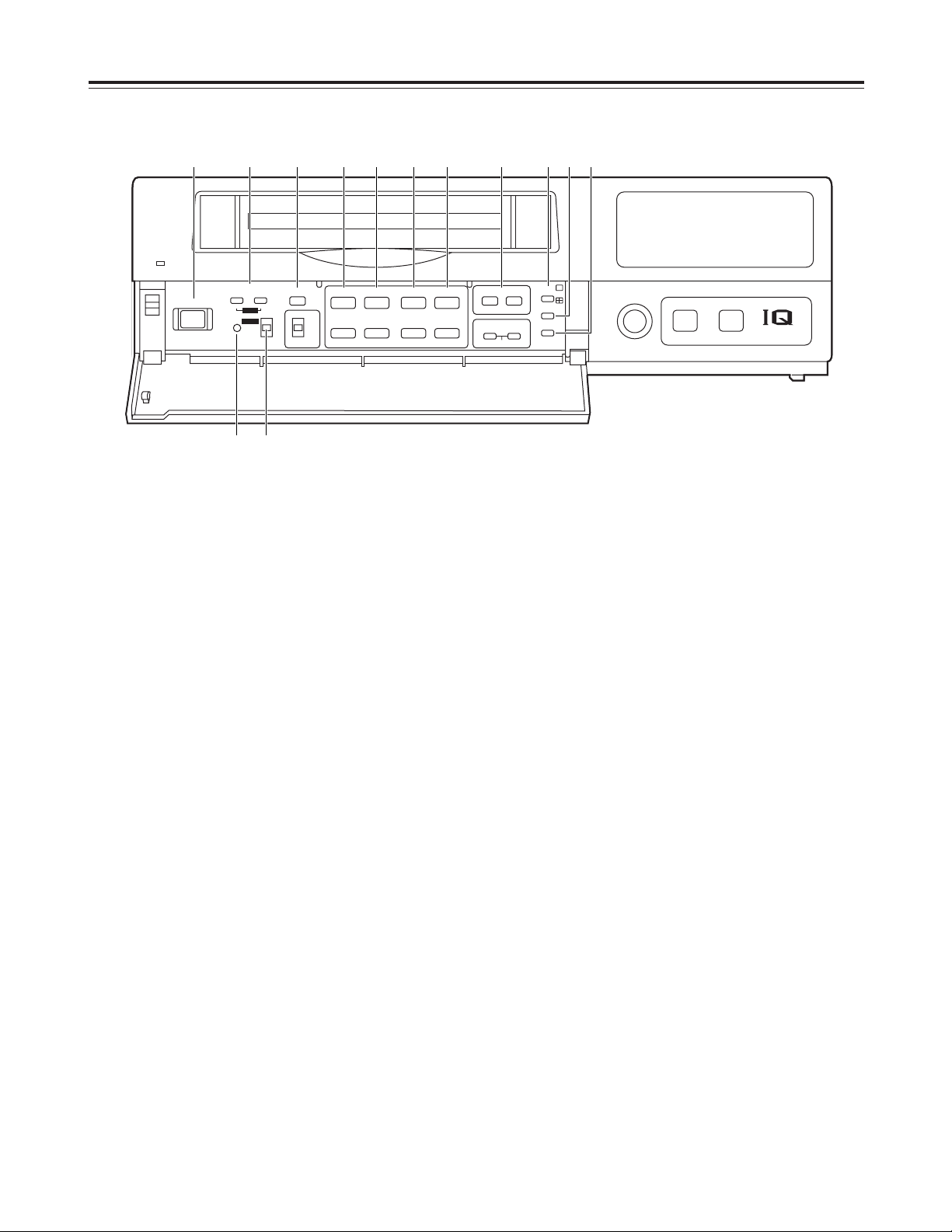
10
Parts and their functions
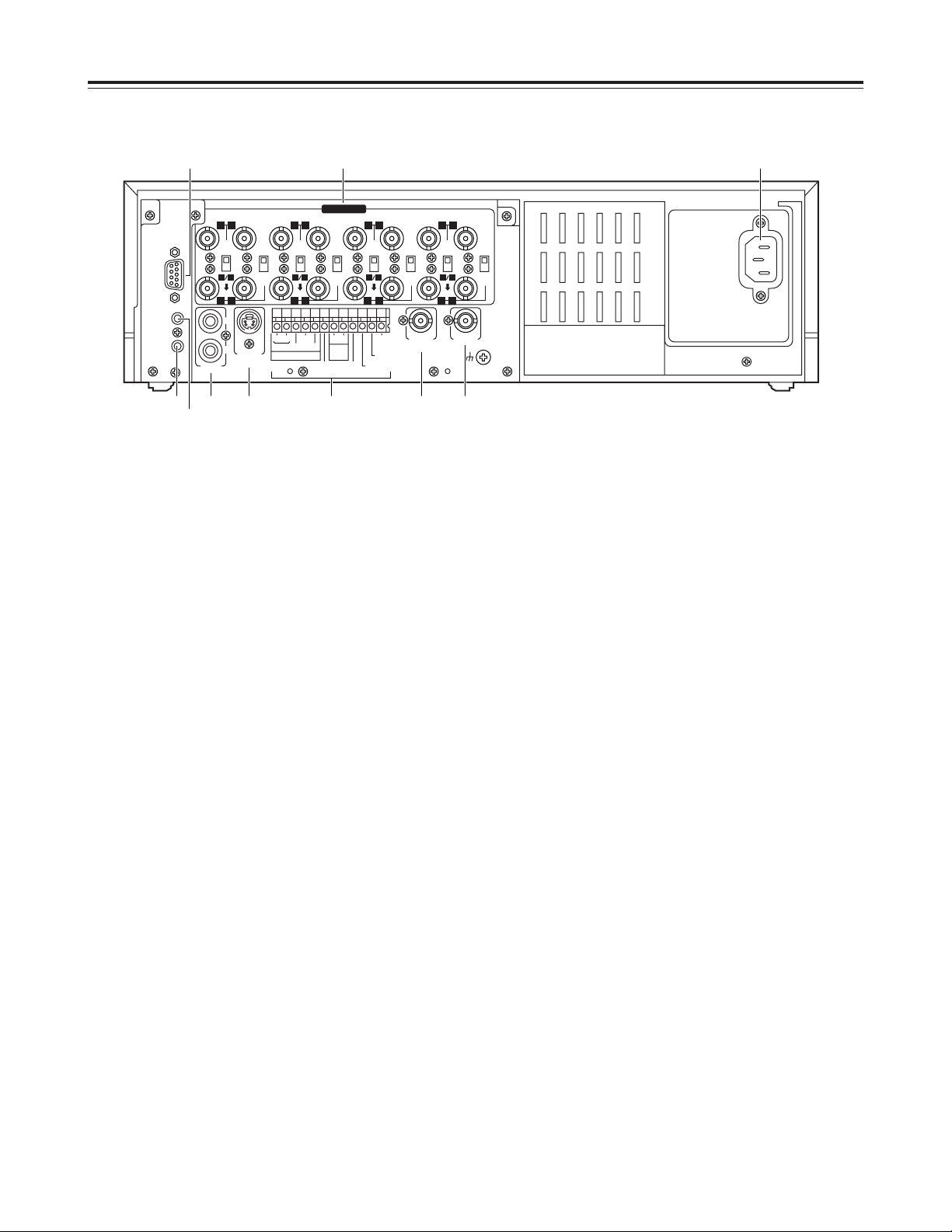
1
CAMERA IN connectors 1to qV(BNC),
75Ω termination/loop through selector switches
1
to 8, 75Ω termination switches 9to
qV
The camera and other external video input signals
(max. 16 inputs) are connected to these
connectors.
To use these connectors, select REC TYPE as the
RECORDING T-MODE & CAMERA setting on
menu screen P3.
<Note>
The 75Ω termination/loop through selector switches
1
to 8have 3 positions.
Switches 9to
qV
have 2 positions, 75 Ω termination
ON and OFF.
2
RS-232C connector
This is used to connect a personal computer or
other such device for controlling the unit.
3
MIC IN jack (M3)
This is used to connect the audio input signals from
the microphone. (600Ω impedance)
4
REMOTE connector
This is used to connect the model AG-A11 remote
controller available as an optional accessory.
5
AUDIO connectors (pin jacks)
These are the audio input and output connectors.
When a microphone has been connected to the
MIC IN jack, the sound from this jack takes
precedence in recording.
6
S-VIDEO OUT connector (4P)
This is used to connect the unit to a device
equipped with an S-video input connector.
7
Terminal section
8
EXT SW IN/VIDEO OUT connector (BNC)
The same video signals are output as the signals
from the VIDEO OUT connector 9. When EXT SW
IN is selected as the EXT SWITCHER MODE
setting on menu screen P7, the connector can be
made to serve as an input connector of the external
switcher.
9
VIDEO OUT connector (BNC)
The video signals from the camera switched by the
internal sequential switcher are output from this
connector during recording.
During playback, the playback pictures of the
recorded tape are output.
The menu screen or time adjustment screen is also
displayed.
:
AC IN socket
One end of the accessory power cord is connected
to this socket, and the other end is connected to a
household AC 120V power outlet.
~AC IN
75
™
ON ON ON ON ON ON ON ON
75
™
CAMERA IN
75
™
75
™
OFF OFF OFF OFF
75
™
OFF
75
™
OFF
75
™
OFF
75
™
OFF
AUDIO
S-VIDEO
OUT
IN
OUT
1
2 GND
IN
REC IN GND
GND
TIME ADJ IN
TAPE END OUT
RESET
ALARM
EXT
TIMER
OUT
IN
OUT
WARNING
/REC OUT
EXT SW IN
/VIDEO OUT
VID
EO OU
T
RS232C
MIC IN
REMOTE
34
12 34 56
78
78
9
10
11
12 13 14 15 16
12 56
1 :
5 6 8 97
3
4
2
Rear panel
11
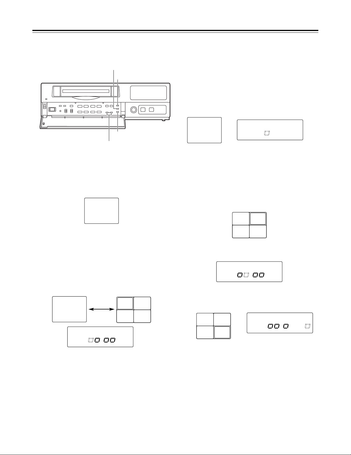
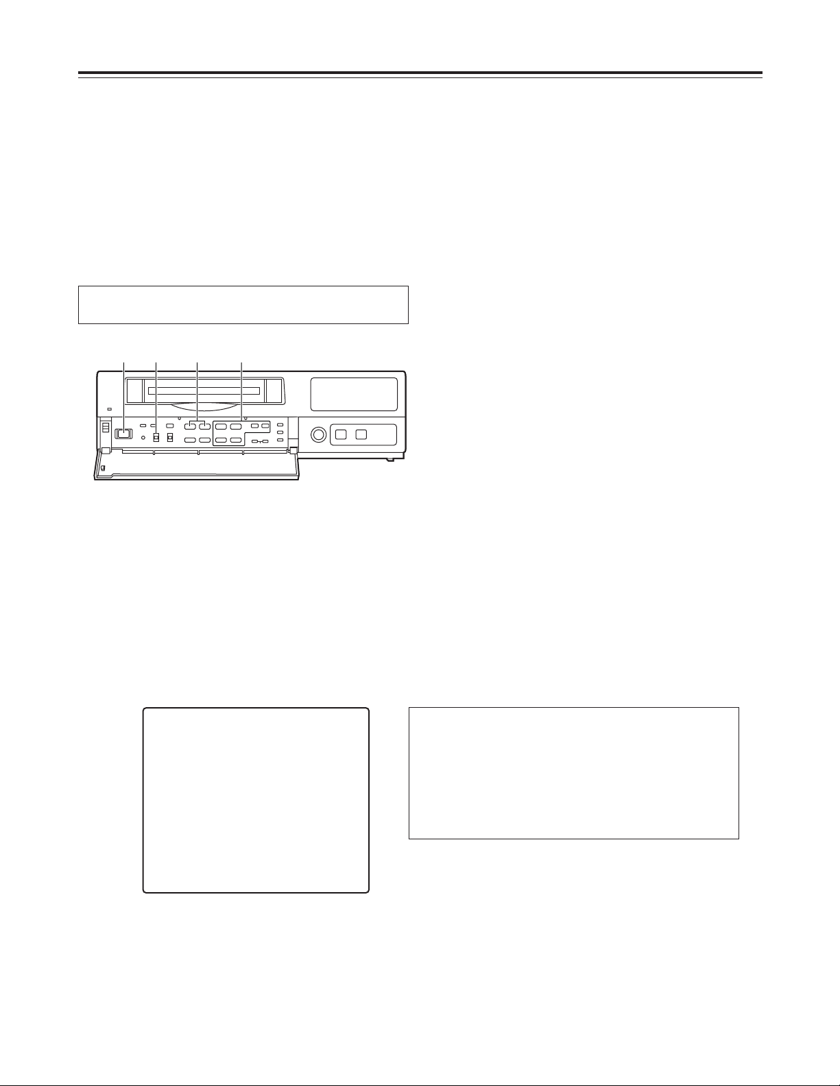
Performing initial settings
1
Set the power switch to ON.
2
Set the PROGRAM switch to the MENU position.
The setting menu screen is shown on the TV
monitor.
4
Proceed as follows to set the date and time.
O
Use the (4) and (3) SHIFT buttons to move the
flashing part to the item whose setting is to be
changed.
O
Use the (2) and (1) SHIFT buttons to move the
flashing part to the column where the setting is
to be changed.
O
Press the (+) or (–) SET button to adjust the
figures.
3
Press the PAGE (+) or PAGE (–) button to display
the P1 TIME/DATE PRESET screen.
The flashing items are ones that can be set.
5
Upon completion of the settings, set the
PROGRAM switch to the OFF position.
The setting menu screen is cleared from the TV
monitor, and the normal mode is restored.
$
Setting the date and time
Before operating the unit, perform the following initial
settings.
<
21
21
65
∫;
34
34
34
H
H
1 2•5 3 4
P1
[TIME/DATE PRESET]
2000- 1-01 SAT
00:00:00
[REC LOCK]
MODE OFF
[HOUR METER]
00000h
12
Performing initial settings
<
21
21
65
∫;
34
34
34
H
H
1 2
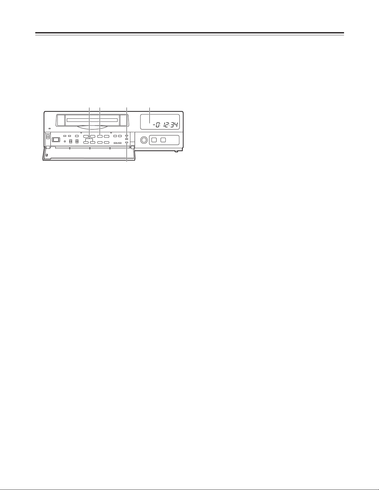
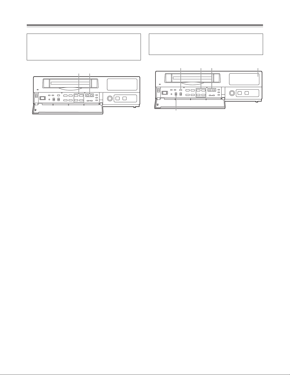
1
Set the power switch to ON.
2
The second digits of the time are reset to “00”
when the 00: button is pressed in synchronization
with the time signal, etc.
They are reset to “00” when the button is pressed
while the display shows 0 to 29 seconds. They are
carried up to 1 minute and set to “00” when it is
pressed while the display shows 30 to 59 seconds.
$
Simple time adjustment
If the clock is running fast or slow, follow the steps
below to adjust it.
When the clock is running up to 30 seconds fast or
slow
<
21
21
65
∫;
34
34
34
H
H
1 2•4 3
1
Set the power switch to ON.
3
The minute and second digits of the time are reset
to “00:00” when the RESET button is pressed in
synchronization with the time signal, etc.
They are reset to “00:00” when the button is
pressed while the display shows 0 to 14 minutes.
They are carried up to 1 hour and set to “00:00”
when it is pressed while the display shows 45 to 59
minutes.
When the clock is running up to 15 minutes fast or
slow
2
Set the PROGRAM switch to the “adjust time”
position.
The counter display shows the current time, and
the “minutes” digits flash.
4
Upon completion of the settings, set the
PROGRAM switch to the OFF position.
13
Performing initial settings
<
21
21
65
∫;
34
34
34
H
H
1 2•6 4 3•5
1
Set the power switch to ON.
2
Set the PROGRAM switch to the “adjust time”
position.
The counter display shows the current time, and
the “minutes” digits flash.
3
Press the SET (+) or SET (–) button to set the
“minutes” digits.
4
Press the PAGE (+) or PAGE (–) button.
The current date appears, and the “date” digits
flash.
6
Upon completion of the settings, set the
PROGRAM switch to the OFF position.
5
Press the SET (+) or SET (–) button to set the
“date” digits.
$
Simple date and time adjustment
If the date and time are wrong, follow the steps below
to adjust them.
14
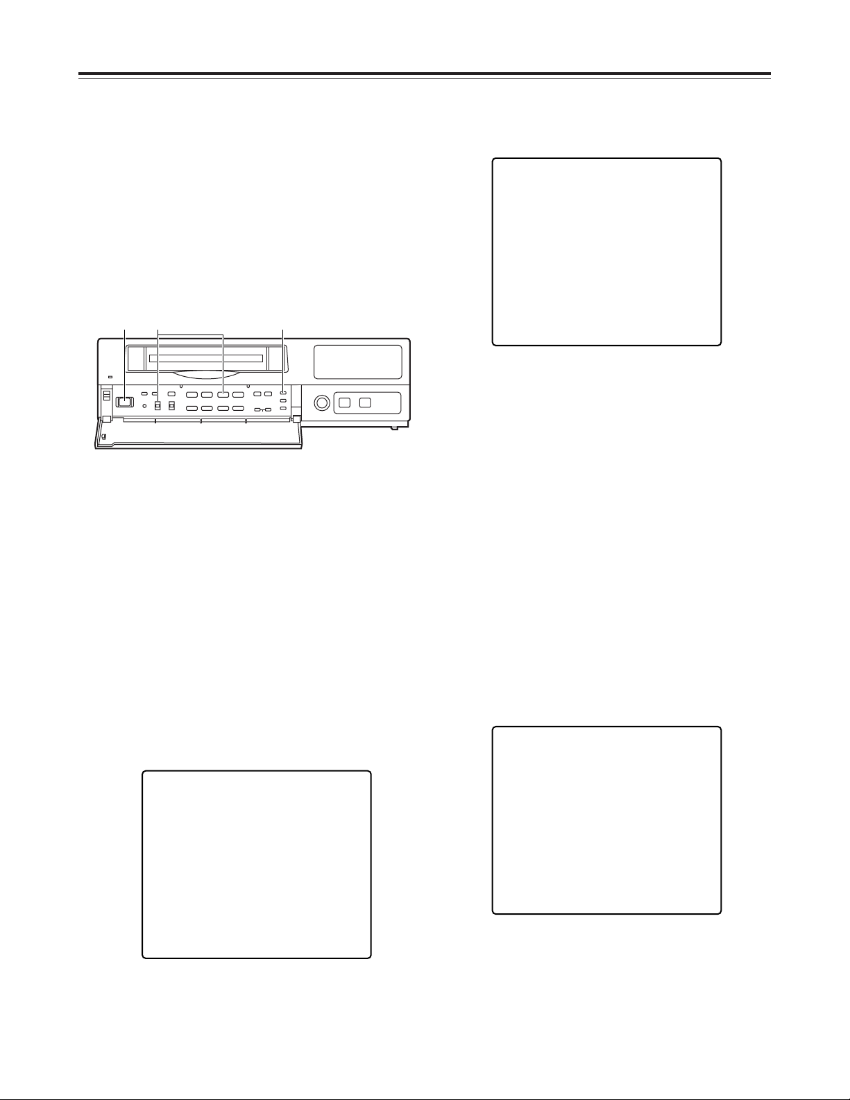
Performing initial settings
1
Set the power switch to ON.
2
Set the PROGRAM switch to the MENU position.
The setting menu screen is shown on the TV
monitor.
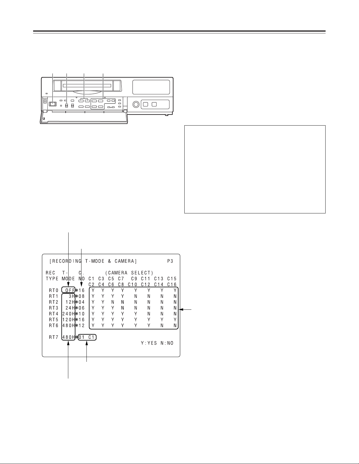
3
Press the PAGE (+) or PAGE (–) button to display
the P3 RECORDING T-MODE & CAMERA screen.
The flashing items are ones that can be set.
Fixed at 01 C1.
The cameras to be used are set here.
The cameras are set in pairs: C1-C2, C3-C4 and so on up to
C15-C16.
“Y” (YES) is set for each pair of cameras that is to be used.
A black burst signal (black screen) is recorded if no video
signals are supplied from a camera even when “Y” (YES)
has been set for that camera.
The number of cameras to be used is
displayed automatically here.
The recording time mode is set here.
Fixed at OFF.
$
Setting the recording time mode and
number of cameras
4
Follow the steps below to set the recording time
mode and number of cameras.
O
Use the (4), (3), (2) and (1) SHIFT buttons
to move the flashing part to the item whose
setting is to be changed.
O
Press the (+) and (–) SET buttons to change the
setting.
<
21
21
65
∫;
34
34
34
H
H
1 2•7 3•5 4•6
On the P3 RECORDING T-MODE & CAMERA
screen, set the number of cameras to be used and
their recording time modes for RT0 through RT7 in
the REC TYPE column ahead of time.
Different kinds of recordings can be undertaken by
setting these two items when normal recording or
timer recording is to be performed.
<Notes>
O
For RT0, T-MODE (recording time mode) is fixed
at OFF.
O
For RT7, the setting for the number of cameras to
be used is fixed at 1 unit for C1.

15
Performing initial settings
7
Upon completion of the settings, set the
PROGRAM switch to the OFF position.
The setting menu screen is cleared from the TV
monitor, and the normal mode is restored.
$
Setting the recording mode
6
Set the recording mode by proceeding as follows.
O
Use the (4) and (3) SHIFT buttons to move the
flashing part to the item whose setting is to be
changed.
O
Press the (+) and (–) SET buttons to change the
setting.
5
Press the PAGE (+) or PAGE (–) button to display
the P4 RECORDING MODE screen.
The flashing items are ones that can be set.
P4 RECORDING MODE screen
O
Either field recording or frame recording is
selected for the FIELD/FRAME item setting.
O
Either high-quality recording or standard quality
recording is selected for the PICTURE QUALITY
item setting.
O
The recording time mode which was set on the P3
RECORDING T-MODE & CAMERA screen is
selected for the REC-TYPE setting.
When type RT0 is selected, the recording time
mode which was set using the TIME MODE
button on the front panel is used for recording.
When a type from RT1 to RT7 is selected, the
recording time mode which was set by RT1 to
RT7 is used for recording.
<Notes>
O
When RT7 is selected for the REC-TYPE item
setting, frame recording will be forcibly performed
regardless of the FIELD/FRAME item setting.
O
Recording is possible at 60 fields a second (which
is the same rate as for video machines used in the
home) if NORMAL is selected as the PICTURE
QUALITY item setting and the recording time
mode is set to 3H when RT7 has been selected
as the REC-TYPE item setting.
O
If the recording time mode is set to 3H when a
setting other than RT7 has been selected for the
REC-TYPE item, recording will be performed
automatically in the high picture quality mode
regardless of the PICTURE QUALITY item
setting.
[RECORDING MODE] P4
FIELD/FRAME FIELD
PICTURE QUALITY HIGH
REC-TYPE RT0 ( OFF¢16)
[ALARM/SENSOR REC]
MODE OFF
FIELD/FRAME FIELD
PICTURE QUALITY HIGH
DURATION 0.5min
BUZZER OFF
REPEAT OFF
GROUP ALARM1 RT0 ( OFF¢16)
GROUP ALARM2 RT0 ( OFF¢16)
16
Performing initial settings
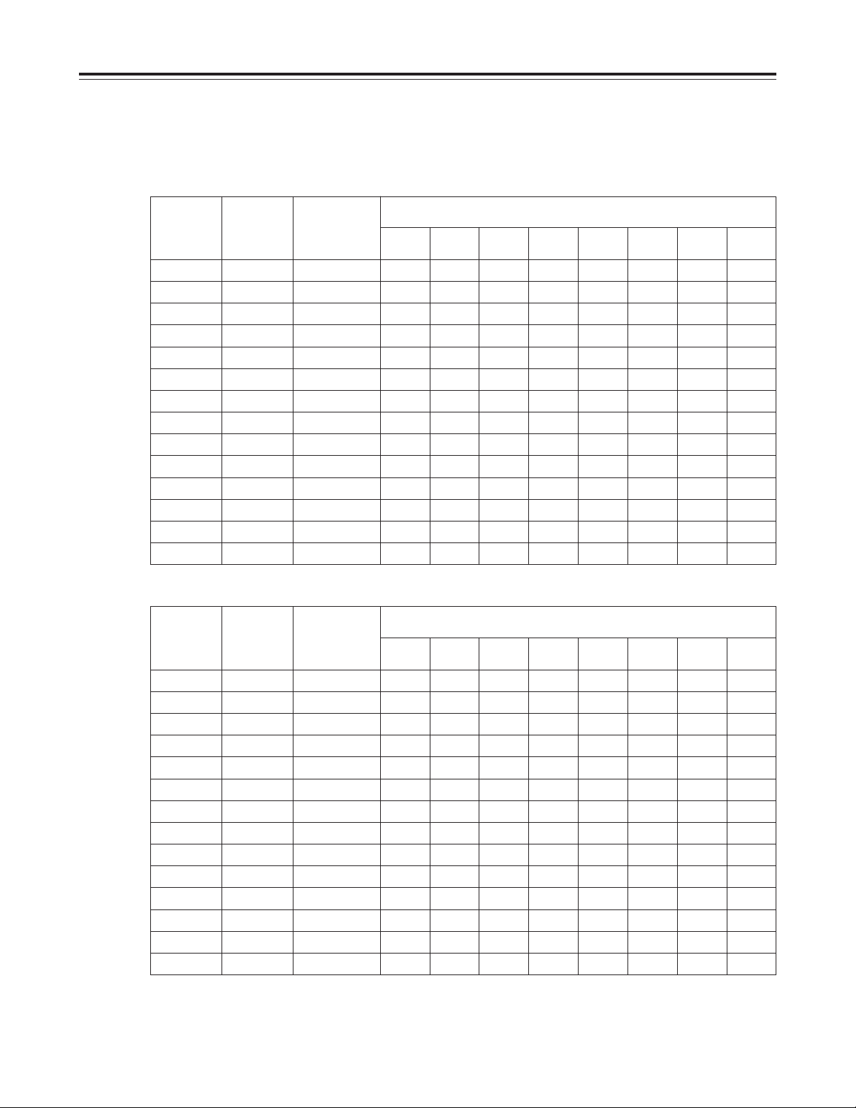
The table below shows the correlation between the recording time modes and number of cameras.
(When an S-VHS 120-minute tape is used)
Set the modes according to what is to be accomplished.
<Notes>
O
The actual recording time will be slightly longer than the figure indicated by the recording time mode.
O
In the frame recording mode, it takes twice as long for the cameras to be switched.
O
When the recording time mode is set to 3H, recording will be performed automatically in the high picture quality mode even
if the standard picture quality mode has been set.
High picture quality mode (field recording)
Recording
time mode
No. of fields
to be
recorded
per sec.
Time taken to
switch
cameras (sec.)
Time taken for recording turn to circulate and return to the first camera
for the no. of cameras connected
2
cameras4cameras6cameras8cameras10cameras12cameras14cameras16cameras
3H 30.00 0.033 0.07 0.13 0.20 0.27 0.33 0.40 0.47 0.53
9H 10.00 0.100 0.20 0.40 0.60 0.80 1.00 1.20 1.40 1.60
12H 6.00 0.167 0.33 0.67 1.00 1.33 1.67 2.00 2.33 2.67
18H 4.29 0.233 0.47 0.93 1.40 1.87 2.33 2.80 3.27 3.73
24H 3.33 0.300 0.60 1.20 1.80 2.40 3.00 3.60 4.20 4.80
48H 1.76 0.567 1.13 2.27 3.40 4.53 5.67 6.80 7.93 9.07
72H 1.20 0.833 1.67 3.33 5.00 6.67 8.33 10.00 11.67 13.33
96H 0.91 1.100 2.20 4.40 6.60 8.80 11.00 13.20 15.40 17.60
120H 0.73 1.367 2.73 5.47 8.20 10.93 13.67 16.40 19.13 21.87
180H 0.49 2.033 4.07 8.13 12.20 16.27 20.33 24.40 28.47 32.53
240H 0.37 2.700 5.40 10.80 16.20 21.60 27.00 32.40 37.80 43.20
360H 0.25 4.033 8.07 16.13 24.20 32.27 40.33 48.40 56.47 64.53
480H 0.19 5.367 10.73 21.47 32.20 42.93 53.67 64.40 75.13 85.87
960H 0.09 10.700 21.40 42.80 64.20 85.60 107.00 128.40 149.80 171.20
Standard picture quality mode (field recording)
Recording
time mode
No. of fields
to be
recorded
per sec.
Time taken to
switch
cameras (sec.)
Time taken for recording turn to circulate and return to the first camera
for the no. of cameras connected
2
cameras4cameras6cameras8cameras10cameras12cameras14cameras16cameras
3H 30.00 0.033 0.07 0.13 0.20 0.27 0.33 0.40 0.47 0.53
9H 20.00 0.050 0.10 0.20 0.30 0.40 0.50 0.60 0.70 0.80
12H 12.00 0.083 0.17 0.33 0.50 0.67 0.83 1.00 1.17 1.33
18H 8.57 0.117 0.23 0.47 0.70 0.93 1.17 1.40 1.63 1.87
24H 6.67 0.150 0.30 0.60 0.90 1.20 1.50 1.80 2.10 2.40
48H 3.53 0.283 0.57 1.13 1.70 2.27 2.83 3.40 3.97 4.53
72H 2.40 0.417 0.83 1.67 2.50 3.33 4.17 5.00 5.83 6.67
96H 1.82 0.550 1.10 2.20 3.30 4.40 5.50 6.60 7.70 8.80
120H 1.46 0.683 1.37 2.73 4.10 5.47 6.83 8.20 9.57 10.93
180H 0.98 1.017 2.03 4.07 6.10 8.13 10.17 12.20 14.23 16.27
240H 0.74 1.350 2.70 5.40 8.10 10.80 13.50 16.20 18.90 21.60
360H 0.50 2.017 4.03 8.07 12.10 16.13 20.17 24.20 28.23 32.27
480H 0.37 2.683 5.37 10.73 16.10 21.47 26.83 32.20 37.57 42.93
960H 0.19 5.350 10.70 21.40 32.10 42.80 53.50 64.20 74.90 85.60
17
A B C D E F G H I J K L M N O P Q R
Actual image
REC REC
1
REC REC
1
REC REC
1
REC REC
1
Frame
recording
REC
1/2
REC
1/2
REC
1/2
REC
1/2
REC
1/2
REC
1/2
REC
1/2
REC
1/2
Field
recording
Camera
No.1
Camera
No.2
Camera
No.3
Camera
No.4
Camera
No.1
Camera
No.2
Camera
No.3
Camera
No.4
Camera
No.1
Camera
No.2
Camera
No.3
Camera
No.4
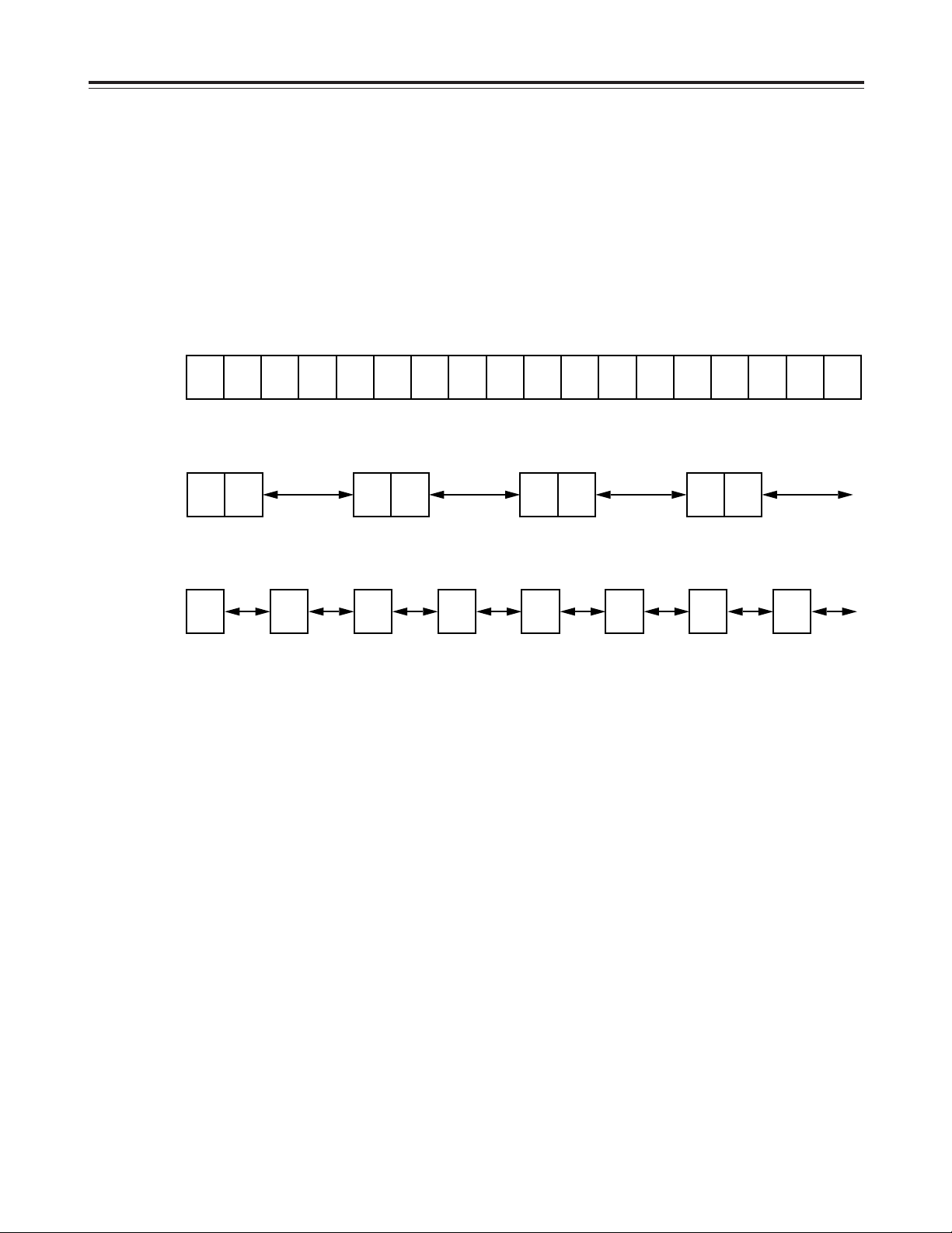
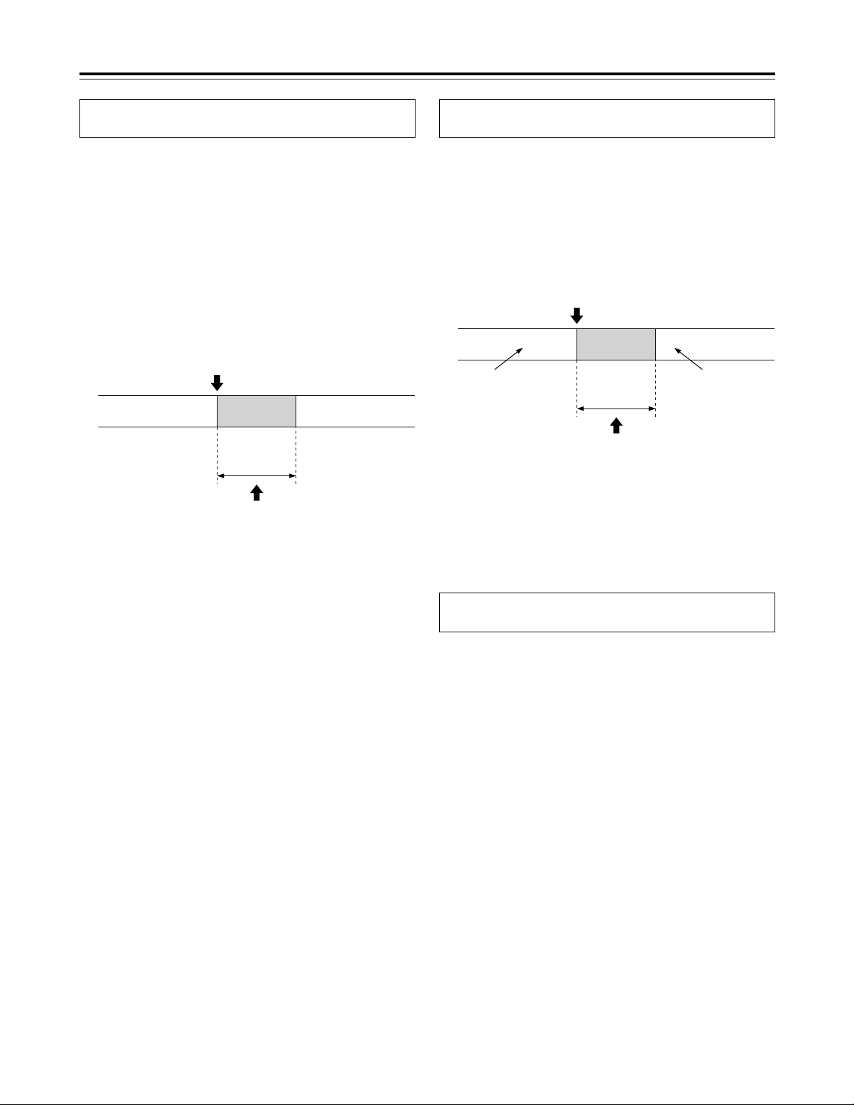
Frame recording and field recording
With frame recording, the image of one camera is
recorded in two fields, and after leaving a fixed
interval, the image of the next camera is recorded.
With field recording, the image of one camera is
recorded in one field, and after leaving half of the
interval for frame recording, the image of the next
camera is recorded.
The gaps between the recorded images are shorter
which enables the cameras to be switched in half the
time taken by frame recording.
Example where cameras 1 to 4 are connected
18
Connections
~AC IN
75
™
ON ON ON ON ON ON ON ON
75
™
CAMERA IN
75
™
75
™
OFF OFF OFF OFF
75
™
OFF
75
™
OFF
75
™
OFF
75
™
OFF
AUDIO
S-VIDEO
OUT
IN
OUT
1
2 GND
IN
REC IN GND
GND
TIME ADJ IN
TAPE END OUT
RESET
ALARM
EXT
TIMER
OUT
IN
OUT
WARNING
/REC OUT
EXT SW IN
/VIDEO OUT
VID
EO OU
T
RS232C
MIC IN
REMOTE
34
12 34 56
78
78
9
10
11
12 13 14 15 16
12 56
No. 1 No. 16
3
2
1
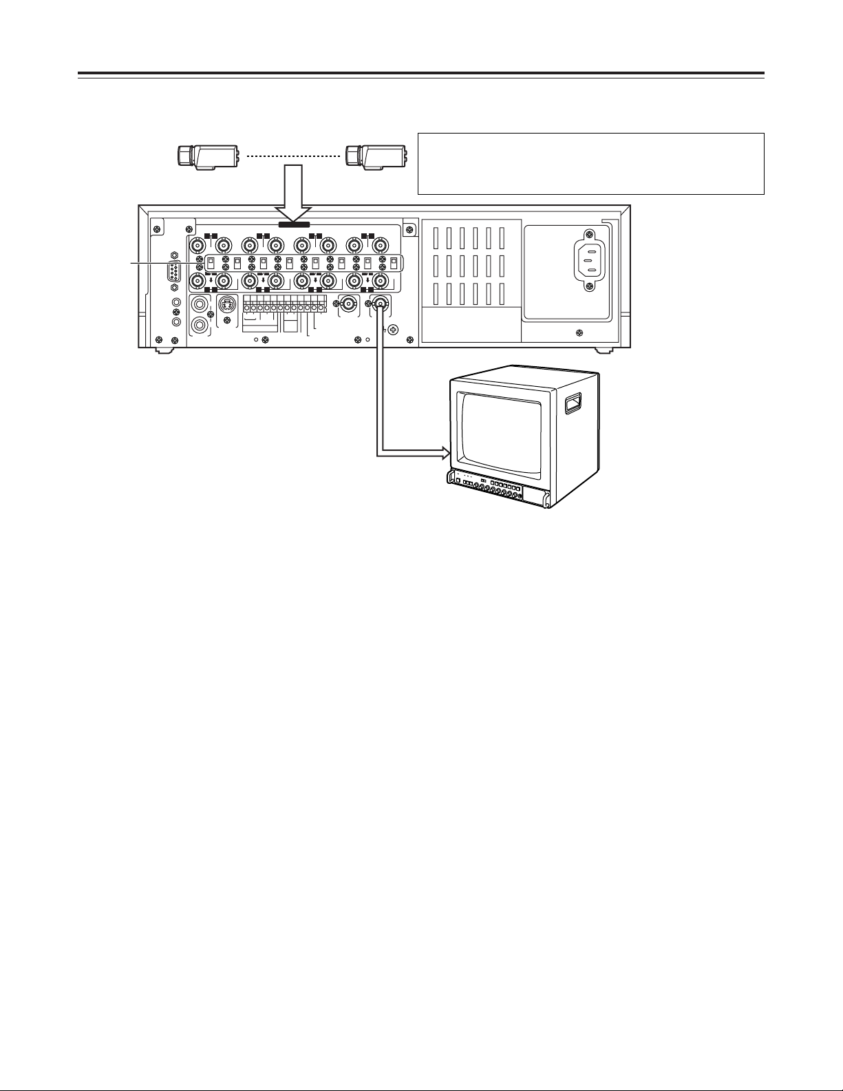
1
Set all 8 of the 75 Ω termination switches to the
ON position.
2
Connect the 16 cameras to CAMERA IN
connectors 1to qV.
3
Connect the TV monitor to the VIDEO OUT
connector.
Example of connections to switch between 16 cameras for recording
<Notes>
O
When connecting line-locked cameras, select ON
for the LL CAMERA item setting on the setting
menu shown on the P7 VIDEO OUT SEQUENCE
screen.
The images on the monitor will shake fractionally:
this is normal and not indicative of malfunctioning.
O
This unit does not contain a compensation circuit.
Install a compensator when the total length of the
cables (coaxial 3C-2V) used to connect the
cameras exceeds 200 meters.
There is no need to install a compensator if the total
length is under 400 meters if coaxial cables (5C-2V)
with minimal transmission loss are used.
This unit does not have an AGC (auto gain control) function for
video signal level adjustment.
Therefore, take due care with the 75 Ω termination for the
peripheral equipment.
19
Connections
~AC IN
75
™
ON ON ON ON ON ON ON ON
75
™
CAMERA IN
75
™
75
™
OFF OFF OFF OFF
75
™
OFF
75
™
OFF
75
™
OFF
75
™
OFF
AUDIO
S-VIDEO
OUT
IN
OUT
1
2 GND
IN
REC IN GND
GND
TIME ADJ IN
TAPE END OUT
RESET
ALARM
EXT
TIMER
OUT
IN
OUT
WARNING
/REC OUT
EXT SW IN
/VIDEO OUT
VID
EO OU
T
RS232C
MIC IN
REMOTE
34
12 34 56
78
78
9
10
11
12 13 14 15 16
12 56
5
34
1
2
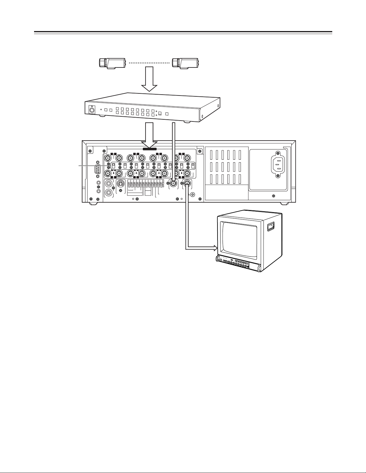
No. 1 No. 16
2
Set all 8 of the unit’s 75 Ω termination switches to
the ON position.
1
Connect the 16 cameras to the CAMERA IN
connectors of the frame switcher, and set the
frame switcher to the multi-screen display (4-in-1,
9-in-1 or 16-in-1 screens, etc.).
3
Connect the 16 camera outputs of the frame
switcher to CAMERA IN connectors 1through
qV
on the unit.
4
Connect the video output of the frame switcher to
the EXT SW IN/VIDEO OUT connector on the unit.
5
Connect the TV monitor to the VIDEO OUT
connector on the unit.
6
Select EXT SW IN as the MODE item setting on
the setting menu shown on the P7 EXT
SWITCHER screen.
The multiple images set by the frame switcher can
be viewed on the TV monitor in all modes except
for the playback mode.
When using a frame switcher during recording to output more than one screen image on the TV monitor

20
<
21
21
65
∫;
34
34
34
H
H
1 43
2
Recording
1
Set the power switch to ON.
When the power is turned on, the POWER lamp
lights, and the buzzer is sounded once.
2
Insert the cassette tape.
Press the EJECT button to eject the cassette tape.
It will not work unless it is pressed firmly.
<Note>
Always use S-VHS cassette tapes. If a VHS tape
is inserted instead, it will be automatically ejected
when the REC button is pressed.
A cassette tape will also be ejected when the REC
button is pressed if its accidental erasure
prevention tab has been broken out.
4
Press the REC button.
Recording is started in the set time mode using the
set cameras which are switched in turn
automatically.
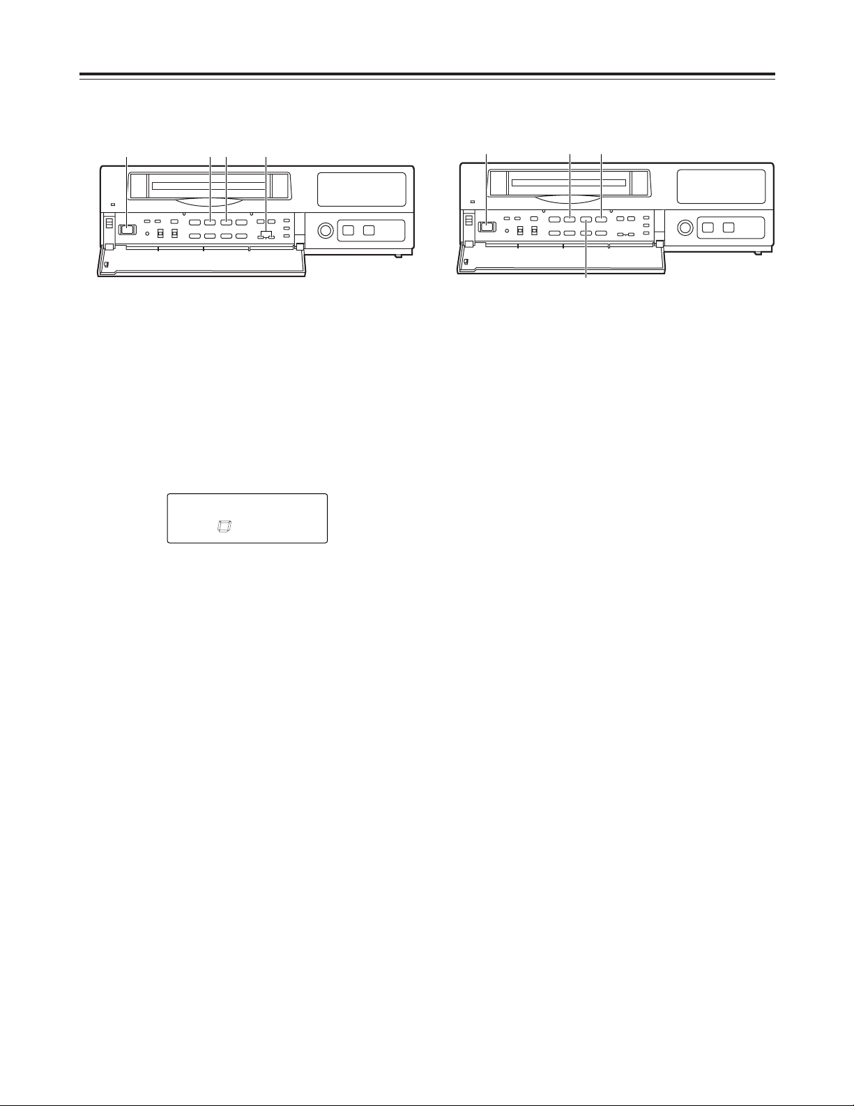
To stop the recording, press the STOP button.
Proceed with recording after having performed the
connections and followed the steps for “Setting the
date and time” (page 11) and “Setting the recording
time mode and number of cameras” (page 14).
EJECT button
STOP button
3
Press the TIME MODE buttons to set the recording
time mode.
When 8 cameras are to be used, select “N” (NO) for
C9—C16 in the RT0 camera setting columns
(CAMERA SELECT) on the setting menu shown on
the P3 RECORDING T-MODE & CAMERA screen.
[RECORDING T-MODE & CAMERA] P3
REC T- C. (CAMERA SELECT)
TYPE MODE NO C1 C3 C5 C7 C9 C11 C13 C15
C2 C4 C6 C8 C10 C12 C14 C16
RT0 OFF¢8 Y Y Y Y N N N N
RT1 OFF¢16 Y Y Y Y Y Y Y Y
RT2 OFF¢16 Y Y Y Y Y Y Y Y
RT3 OFF¢16 Y Y Y Y Y Y Y Y
RT4 OFF¢16 Y Y Y Y Y Y Y Y
RT5 OFF¢16 Y Y Y Y Y Y Y Y
RT6 OFF¢16 Y Y Y Y Y Y Y Y
RT7 OFF¢01 C1
Y:YES N:NO
This unit is designed to provide the high level of
reliability required of a time lapse recorder for use
in such applications as surveillance, security and
monitoring.
In order to ensure that this unit will perform
reliably in recording operations, it is
recommended that the following Panasonic video
tape be used:
S-VHS tape: ST-120 series (120-minute tape)
When recording always in the same recording time
mode instead of setting the mode using the TIME
MODE button, set RT1 through RT7 for the REC
TYPE item on the setting menu shown on the P3
RECORDING T-MODE & CAMERA screen, and set
the REC TYPE (RT1 through RT7) to be used for
recording for the REC-TYPE item on the P4
RECORDING MODE screen.
Select RT7 when using one camera for the
recording. This enables the images of the camera
connected to the camera input 1connector to be
recorded.
21
Playback
Still-picture playback
Normal playback
1
Set the power switch to ON, and insert the
cassette tape.
2
Press the PLAY button to start playback.
When 8 cameras are being used, the 8 camera
numbers appear on the camera number display of
the display tube, and the number of the camera
whose pictures are being played back is enclosed
in a square.
4
To stop the playback, press the STOP button.
<
21
21
65
∫;
34
34
34
H
H
2 41
3
1
Set the power switch to ON, and insert the
cassette tape.
2
Press the PLAY button to start playback.
3
Press the PAUSE STILL button.
The unit is now set to the still-picture playback
mode.
(When the frame advance button is pressed in the
still-picture playback mode, the tape is played back
one frame at a time.)
4
Press the PLAY button again to return to normal
playback.
5
To stop the playback, press the STOP button.
<
21
21
65
∫;
34
34
34
H
H
2•4531
CAMERA
172
8
5643
3
Press the CAMERA buttons to set the playback
camera.
<Note>
When video noise in blocks interferes with playback,
press the (+) or (–) tracking button until the noise is
eliminated.
<Note>
If a switch is made to cameras No.13 to 16 when a
tape which was frame-recorded using cameras No.13
to 16 is being played back in the still-picture playback
mode, blue background signals will be output.
<
21
21
65
∫;
34
34
34
H
H
22
Changing over the screen display
1
During playback, one screen is displayed on the
TV monitor.
3
Press the RESET button to change over to the 4in-1 screen display.
Each time the RESET button is now pressed, the
display is switched between the 1-screen and 4-in1 screen.
Changing between the 1-screen and 4-in-1
screen display
Changing over the screen during
playback
1
1
Press the SEARCH button to move to the screen
with the white border.
2
43
1
C01 C02
C03 C04
2
Press the CAMERA button to set the camera.
3
Repeat steps 1 and 2 for the other screens to set
the camera for each.
1
2
43
1
C01 C02
C03 C04
CAMERA
172
8
56
12
11
9
43
10
The pictures recorded by a specific camera can be
monitored by pressing the CAMERA button during
playback.
When monitoring the pictures recorded by specific
cameras on the four screens in the 4-in-1 screen
display mode
Switching between the cameras
In the 1-screen display mode
In the 4-in-1 screen display mode
2
2
63
1
C01 C02
C03 C06
Four camera numbers are enclosed in squares on the
camera number display of the display tube, and the
square corresponding to the number of the selected
camera flashes. In addition, the numbers of the
cameras (C01/C02/C03/C04) appear in the center of
the TV monitor.
CAMERA
172
8
56
12
11
9
43
10
CAMERA
172
8
56
12
11
9
43
10
CAMERA
172
8
56
12
11
9
43
10
2
Press the COUNTER button to establish the
camera number display mode.
SEARCH button
RESET button
CAMERA button
COUNTER button
<Note>
It is not possible to switch to the 4-in-1 screen display
when a tape which was frame-recorded using
cameras No.13 to 16 is to be played back.
23
<
21
21
65
∫;
34
34
34
H
H
214
3
M
COUNT
Useful functions
Memory stop
2
Press the COUNTER button to establish the
counter display mode.
1
Press the STOP button to set the unit to the stop
mode.
3
Press the SEARCH button.
Check that “M” lights on the display tube and that
the memory stop mode is established.
Press the SEARCH button again if “AS” has
lighted.
4
Press the REW button if the counter reading is
higher than “00:00:00”; conversely, press the FF
button if it is lower (a negative value) than
“00:00:00.”
5
The counter reading approaches “00:00:00,” and
the tape is automatically set to the stop mode.
This function serves to rewind or fast forward the tape
to the “00:00:00” counter position and then
automatically set the unit to the stop mode when a
regular operation is being performed.
“M” lights.

24
Useful functions
Alarm recording and sensor
(emergency) recording
Alarm recording
This function enables recording with changes made to
the time mode and/or cameras used for recording
when an alarm signal (see page 35 for details on the
alarm recording connections) is input during
recording.
Sensor (emergency) recording
This function enables recording with changes made to
the time mode and/or cameras used for recording as
soon as an alarm signal is input even when the unit’s
power is off.
1
Set the POWER switch to ON, and insert the
cassette tape.
2
Set the PROGRAM switch to the MENU position.
The setting menu screen now appears on the TV
monitor.
3
Press the PAGE (+) or PAGE (–) button to display
the P4 ALARM/SENSOR REC screen.
The flashing items are ones that can be set.
4
Take the following steps to set the recording mode
to be established when an alarm signal is input:
O
Use the (4) and (3) SHIFT buttons to move the
flashing part to the item whose setting is to be
changed.
O
Press the (+) and (–) SET buttons, and change
the setting.
<Notes>
O
Alarm recording and sensor recording are
selected using the MODE item.
Select OFF as the MODE item setting if
recording is not to be performed when an alarm
signal is input.
O
The recording time (DURATION) is set as
follows between 30 seconds and 10 minutes:
CONTINUE (up to the tape-end) or MANUAL
(while the alarm signal is input).
5
When the settings are completed, set the
PROGRAM switch to the OFF position.
The setting menu screen is cleared from the TV
monitor, and the normal mode is restored.
<
21
21
65
∫;
34
34
34
H
H
1 2•5 3 4
ALARM
[RECORDING MODE] P4
FIELD/FRAME FIELD
PICTURE QUALITY HIGH
REC-TYPE RT0 ( OFF¢16)
[ALARM/SENSOR REC]
MODE OFF
FIELD/FRAME FIELD
PICTURE QUALITY HIGH
DURATION 0.5min
BUZZER OFF
REPEAT OFF
GROUP ALARM1 RT0 ( OFF¢16)
GROUP ALARM2 RT0 ( OFF¢16)
25
The power is off or
the tape is stopped
or in the internal
timer standby mode.
The power is off or
the tape is stopped
or in the internal
timer standby mode.
Sensor
recording
Alarm signal input
Recording
time
(DURATION)
Recording proceeds in the sensor
recording mode which has been set.
Useful functions
Sensor recording starts as soon as an alarm signal is
input even when the unit’s power is off or the tape has
stopped.
O
When OFF or ALARM is selected as the MODE
setting on the menu screen shown on P4
ALARM/SENSOR REC, the sensor recording
function does not work.
<Note>
When sensor recording is completed, the operation
prior to the alarm signal input is restored.
Press the REC button to start recording.
The alarm recording mode is established when an
alarm signal is input.
Once alarm recording is initiated, “ALARM” flashes on
the display tube.
When the STOP button is pressed, the display is
cleared, and recording stops.
O
When OFF or SENSOR is selected as the MODE
setting on the menu screen shown on P4
ALARM/SENSOR REC, the alarm recording
function does not work.
<Note>
When alarm recording is completed, the operation
prior to the alarm signal input is restored.
Recording Recording
Alarm
recording
Alarm signal input
Recording
time
(DURATION)
Recording proceeds in the alarm
recording mode which has been set.
When ALARM is selected as the MODE item
setting
When SENSOR is selected as the MODE item
setting
Both alarm recording and sensor recording are
performed.
If an alarm signal is input during recording, the alarm
recording mode is established, and when it is input
while the unit’s power is off or the tape has stopped,
sensor recording is started.
When ALARM/SENSOR is selected as the MODE
item setting
26
<
21
21
65
∫;
34
34
34
H
H
1 2
Useful functions
Alarm memory recall and power
loss memory recall
Alarm memory recall is a function for storing in the
memory those dates/times and number of occasions
on which the alarm recording and sensor recording
functions were activated.
Power loss memory recall is a function for storing in
the memory those dates/times and number of
occasions on which the primary power supply was
shut off due to a power outage, etc.
RESET button
<Notes>
O
Data for up to 8 alarms is stored on the ALARM
RECALL screen whereas data for up to 4 power
losses is stored on the POWER LOSS MEMORY
screen.
O
A total of 99 alarms and 99 power losses are stored
in the memory.
When 99 is exceeded, the count returns to “00.”
O
As with alarm recordings, the sensor recordings are
stored as alarm memory data.
O
The alarm memory data and power loss memory
data are stored in the memory circuit inside the unit.
They are not recorded on the tape.
O
When the PROGRAM switch is set to any position
except MENU, the ALARM RECALL screen and
POWER LOSS MEMORY screen displays are
cleared.
O
When the RESET button is pressed while the
ALARM RECALL screen is displayed, the memory
can be cleared, but the POWER LOSS MEMORY
screen is not cleared.
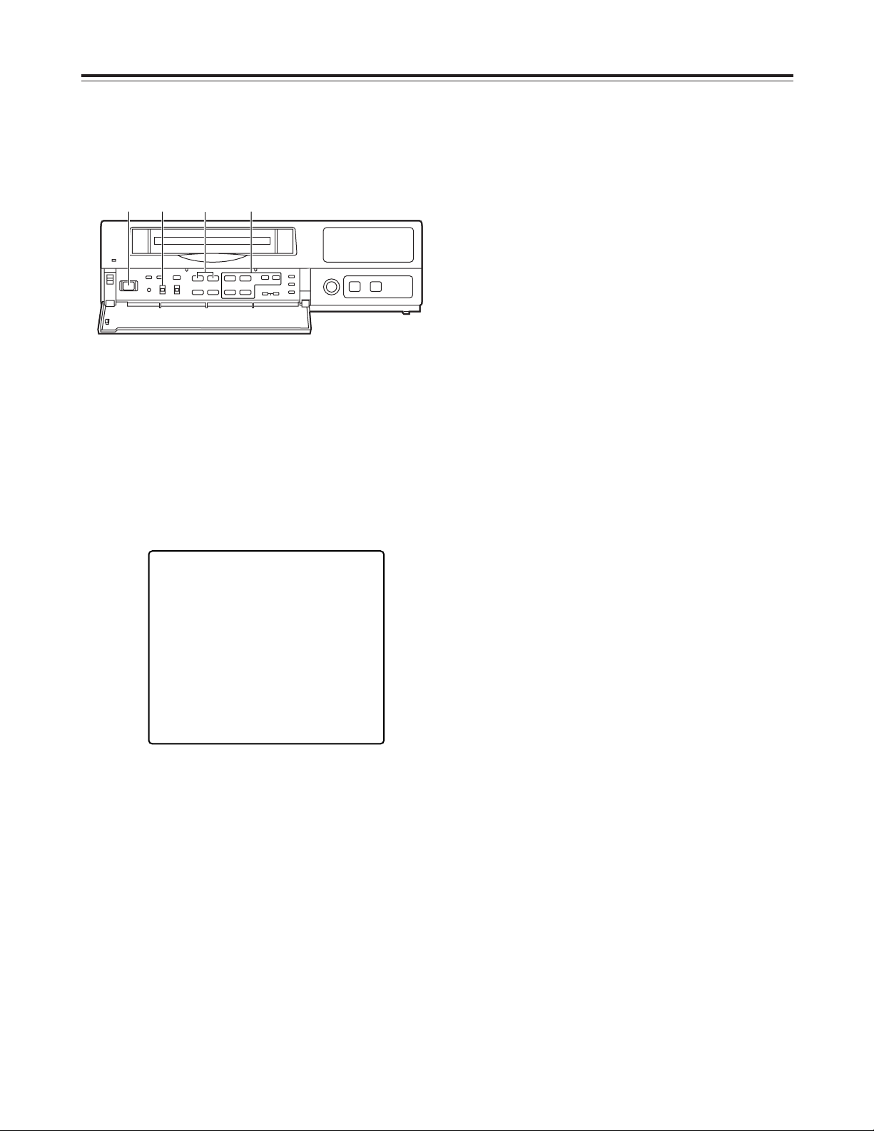
The following display appears when alarm recording
was never performed or when the primary power
supply was never shut off.
1
Set the POWER switch to ON.
2
Set the PROGRAM switch to the MENU position
while holding down the STOP button.
The ALARM RECALL screen and POWER LOSS
MEMORY screen now appear.
The alarm number/s and dates/times when the
alarm signal was input are displayed on the
ALARM RECALL screen.
The number of times the primary power source has
been shut off and the dates/times when this
happened are displayed on the POWER LOSS
MEMORY screen.
(Data is displayed in sequence with the latest at
the top of the screen.)
[ALARM RECALL]
¢¢ ¢¢–¢¢–¢¢¢¢ ¢¢:¢¢
¢¢ ¢¢–¢¢–¢¢¢¢ ¢¢:¢¢
¢¢ ¢¢–¢¢–¢¢¢¢ ¢¢:¢¢
¢¢ ¢¢–¢¢–¢¢¢¢ ¢¢:¢¢
¢¢ ¢¢–¢¢–¢¢¢¢ ¢¢:¢¢
¢¢ ¢¢–¢¢–¢¢¢¢ ¢¢:¢¢
¢¢ ¢¢–¢¢–¢¢¢¢ ¢¢:¢¢
¢¢ ¢¢–¢¢–¢¢¢¢ ¢¢:¢¢
[POWER LOSS MEMORY]
¢¢ ¢¢–¢¢–¢¢¢¢ ¢¢:¢¢
¢¢ ¢¢–¢¢–¢¢¢¢ ¢¢:¢¢
¢¢ ¢¢–¢¢–¢¢¢¢ ¢¢:¢¢
¢¢ ¢¢–¢¢–¢¢¢¢ ¢¢:¢¢
[ALARM RECALL]
¢¢ ¢¢–¢¢–¢¢¢¢ ¢¢:¢¢
¢¢ ¢¢–¢¢–¢¢¢¢ ¢¢:¢¢
¢¢ ¢¢–¢¢–¢¢¢¢ ¢¢:¢¢
¢¢ ¢¢–¢¢–¢¢¢¢ ¢¢:¢¢
¢¢ ¢¢–¢¢–¢¢¢¢ ¢¢:¢¢
¢¢ ¢¢–¢¢–¢¢¢¢ ¢¢:¢¢
¢¢ ¢¢–¢¢–¢¢¢¢ ¢¢:¢¢
¢¢ ¢¢–¢¢–¢¢¢¢ ¢¢:¢¢
[POWER LOSS MEMORY]
14 12 – 01 – 2000 12:00
13 10 – 05 – 2000 10:30
12 08 – 10 – 2000 9:20
11 3 – 02 – 2000 7:00
[ALARM RECALL]
29 12 – 30 – 2000 3:15
28 12 – 04 – 2000 12:10
27 10 – 25 – 2000 2:20
26 9 – 10 – 2000 2:30
25 8 – 11 – 2000 6:55
24 5 – 10 – 2000 3:22
23 4 – 11 – 2000 6:55
22 3 – 10 – 2000 3:22
[POWER LOSS MEMORY]
14 12 – 01 – 2000 12:00
13 10 – 05 – 2000 10:30
12 08 – 10 – 2000 9:20
11 3 – 02 – 2000 7:00
27
Useful functions
Search playback (cue/review)
1
Set the POWER switch to ON, and insert the
cassette tape.
2
Press the PLAY button to start playback.
3
Press the FF button or REW button.
The unit performs search playback (cue or review)
while the FF button or REW button is held down.
Normal playback is restored when the FF button or
REW button is released.
<
21
21
65
∫;
34
34
34
H
H
21
3
<Notes>
O
To release the alarm search mode, press the
SEARCH button again to clear “AS” from the
display tube.
O
The alarm search function can be used to search
for only those alarm recording sections which were
recorded for more than 30 seconds in the 3-hour, 9hour, 12-hour, 18-hour or 24-hour recording time
mode.
O
When the FF button or REW button is pressed
during playback, search playback (cue or review) is
initiated, and even when the button is released,
search playback will continue if the unit is in the
alarm search mode.
2
Press the COUNTER button to establish the
counter display mode.
4
While the unit is in the stop, fast forward or rewind
mode, press the REW or FF button.
The first alarm recording section is searched in the
direction corresponding to the button pressed, and
the unit is set to the still-picture playback mode.
3
Press the SEARCH button.
Check that “AS” lights on the display tube and that
the alarm search mode is established.
Press the SEARCH button again if “M” has lighted.
5
To play back the section, press the PLAY button.
Alarm search
(alarm recording section search)
1
Set the POWER switch to ON, and insert the
cassette tape containing the alarm recording.
<
21
21
65
∫;
34
34
34
H
H
251
4
3
AS
COUNT
“AS” lights.
<Notes>
O
When search playback is performed with a tape
which was frame-recorded using cameras No.13 to
16, the recorded images of all the cameras are
mixed and output even if a particular camera is
selected.
O
The picture will become quite blurred when search
playback is performed for a tape which was fieldrecorded in the standard picture quality mode. This
is normal and not indicative of malfunctioning.
28
<
21
21
65
∫;
34
34
34
H
H
51
3 2
S
TIME
4
Useful functions
3
Press the SEARCH button.
“S” lights on the display tube, and the TIME DATE
SEARCH screen appears on the TV monitor.
The time at which the recording was ended is
shown on the TIME DATE SEARCH screen.
When the tape is played back, the date and time
recorded on the tape are displayed.
When the RESET button is now pressed, the
display changes to the time at which the recording
was started.
2
Press the COUNTER button to establish the time
display mode.
Time/date search
This function is used to search for a particular
recording section by designating its date and time.
1
Set the POWER switch to ON, and insert the
cassette tape.
“S” lights.
4
Follow the steps below to set the search date and
time.
O
Use the (2) and (1) SHIFT buttons to move the
flashing part to the item whose setting is to be
changed.
O
Press the (+) and (–) SET buttons to set the
figure.
5
Press the PLAY button or REV PLAY button.
The recording section with the designated date and
time is now searched.
<Notes>
O
The tape comes to a stop at its end or start if no
recording section with the date and time was
found as a result of the search.
O
When the tape is stopped during recording, it
will stop at the border between the new
recording and old recording, and the continuity
in the date and time recorded on the tape will be
lost.
In this state, searches may not be performed
properly.
When the date or time to be searched is in the
newly recorded section, it is recommended that
the REV PLAY button be pressed. By pressing
this button, the tape is returned a little in the
reverse direction, the date and time data is
loaded, and the search is performed using this
data as a reference.
6
To release the time/date search mode, press any
of the function buttons.
[TIME DATE SEARCH]
12 – 25 10 : 25A
RESET : REC START TIME PRESET
PLAY : SEARCH START
RESET button
29
Useful functions
Internal timer recording
Recording can be started and ended at the desired
times which are set using the internal timer.
<Note>
Before setting the internal timer recording, complete
the connections as well as the steps for “Setting the
date and time” (page 11) and “Setting the recording
time mode and number of cameras” (page 14).
Registering programs for internal timer
recording
1
Set the POWER switch to ON, and insert the
cassette tape.
2
Set the PROGRAM switch to the MENU position.
The setting menu screen now appears on the TV
monitor.
3
Press the PAGE (+) or PAGE (–) button to display
the P8 PROGRAM TIMER screen.
The flashing items are ones that can be set.
4
Take the following steps to set the timer recording
mode.
O
Use the (4), (3), (2) and (1) SHIFT buttons
to move the flashing part to the item whose
setting is to be changed.
O
Press the (+) and (–) SET buttons, and change
the setting.
[PROGRAM TIMER] P8
(TIMER) START END REC-TYPE
PGM1 0:00 0:00 RT0 ( OFF¢16)
PGM2 0:00 0:00 RT0 ( OFF¢16)
PGM3 0:00 0:00 RT0 ( OFF¢16)
PGM4 0:00 0:00 RT0 ( OFF¢16)
PGM5 0:00 0:00 RT0 ( OFF¢16)
PGM6 0:00 0:00 RT0 ( OFF¢16)
PGM7 0:00 0:00 RT0 ( OFF¢16)
PGM8 0:00 0:00 RT0 ( OFF¢16)
[INTERNAL WEEKLY TIMER]
(SUN MON TUE WED THU FRI SAT DLY)
¢¢¢ ¢¢¢ ¢¢¢ ¢¢¢ ¢¢¢ ¢¢¢ ¢¢¢ ¢¢¢
¢¢¢ ¢¢¢ ¢¢¢ ¢¢¢ ¢¢¢ ¢¢¢ ¢¢¢ ¢¢¢
(TIMER)
Register the programs (PGM1-PGM8) in this column when using
the internal timer to record them.
START
The recording start times are set in this column.
END
The recording end times are set in this column.
REC-TYPE
The recording type (RT0 to RT7) are set in this column.
<
21
21
65
∫;
34
34
34
H
H
1 2 3 4
30
<
21
21
65
∫;
34
34
34
H
H
INT
7
9
10 8
Useful functions
Weekly timer
This function is used to record for the programmed
duration every week at the same time on the same
day.
9
Upon completion of the settings, set the
PROGRAM switch to the OFF position.
The setting menu screen is cleared from the TV
monitor, and the normal mode is restored.
10
Press the TIMER MODE button on the front
panel and set it to the internal timer recording
mode (the “INT” lamp lights on the display tube).
<Notes>
O
If the cassette tape has not been inserted or
its accidental erasure prevention tab has
been broken out, the buzzer will sound, and
the INT lamp will flash.
O
To release the internal timer recording mode,
press the TIMER MODE button and turn off
the INT lamp on the display tube.
5
Use the (4), (3), (2) and (1) SHIFT buttons to
move the flashing part to the day-of-the-week
(SUN through SAT) item on the INTERNAL
WEEKLY TIMER screen.
6
Press the (+) and (–) SET buttons, and set the
programs (PGM1-PGM8) registered on the
PROGRAM TIMER screen for the days of the
week concerned.
O
Two programs each—one on the top line and
the other on the bottom—can be set for each
day of the week.
Leave “
¢¢¢
” unchanged where no programs
are to be set.
O
When programmed time zone overlap on the
same day, the program on the top line takes
precedence.
Daily timer
This function is used to record for the programmed
duration at the same time every day.
7
Use the (4), (3), (2) and (1) SHIFT buttons to
move the flashing part to the DLY item.
8
As with the weekly timer function, press the (+) and
(–) SET buttons, and set the programs (PGM1PGM8) registered on the PROGRAM TIMER
screen.
<Note>
If the time zone programmed using the daily timer
overlaps the time zone programmed using the weekly
timer, the weekly timer will take precedence.
<
21
21
65
∫;
34
34
34
H
H
5 6
“INT” lamp
 Loading...