

Omron E5ZN-DRT Operation Manual

Cat. No. H119-E1-01
E5ZN-DRT
DeviceNet Communications Unit
for E5ZN Temperature Controllers
OPERATION MANUAL

E5ZN-DRT
DeviceNet Communications Unit
for E5ZN Temperature Controllers
Operation Manual
Produced October 2002

iv

Notice:
r
f
OMRON products are manufactured for use accordin g to proper procedures by a qualified operator
and only for the purposes described in this manual.
The following conventions are used to ind icate and classify pr ecautions in this manual . Always heed
the information provided with them . Failure to heed precautions can result in in jur y to people or damage to property.
!DANGER Indicates an immine ntly hazardous situation whi ch, if not avoided, will result in death or
serious inj ury.
!WARNING Indicates a potentially hazardous situatio n which, if not avoided, could resu lt in death or
serious inj ury.
!Caution Indicates a potentially hazardous si tuation which, if not avoided, may result in minor or
moderate injury, or property damage.
OMRON Product References
All OMRON products are capitalized in this manual. The word “Unit” is also capitalized when it refers to
an OMRON product, regardless of whether or not it appears in the proper name of the product.
The abbreviation “Ch,” which appears in some displ ays and on some OMRON products, often means
“word” and is abbreviated “Wd” in documentation in this sense.
The abbreviation “PV” is used in this manual to indic ate the process value of the E5ZN Temperature
Controller.
The abbreviation “PLC” means P rogrammable Controller. “PC” is used, however, in some Programming Device displays to mean Programmable Controller.
Visual Aids
The following headings appear in the le ft column of the manual to help you locate different types of
information.
OMRON, 2002
All rights reserved. No part of this publication may be reproduced, stored in a retrieval system, or transmitted, in an y fo rm, o
by any means, mechanical, electronic, photocopying, recording, or otherwise, without the prior written permission o
OMRON.
No patent liability is assumed with respect to th e use of the in fo rmation c ontain ed he rein. M oreover, because OMRON is constantly striving to improve its high-quality products, the information contained in this manual is subject to change without
notice. Every precaution has been taken in the preparation of this manual. Nevertheless, OMRON assumes no responsibility
for errors or omissions. Neither is any liability assumed for damages resulting from the use of the information contained in
this publication.
Note Indicates information of pa rticular interest for efficient and convenient opera-
tion of the product.
1,2,3... 1. Indicates lists of one sort or another, such as procedures, checklists, etc.
v

vi

TABLE OF CONTENTS
PRECAUTIONS . . . . . . . . . . . . . . . . . . . . . . . . . . . . . . . . . . . xi
1 Intended Audience. . . . . . . . . . . . . . . . . . . . . . . . . . . . . . . . . . . . . . . . . . . . . . . . . . . . . . . . . xii
2 General Precautions. . . . . . . . . . . . . . . . . . . . . . . . . . . . . . . . . . . . . . . . . . . . . . . . . . . . . . . . xii
3 Safety Precautions . . . . . . . . . . . . . . . . . . . . . . . . . . . . . . . . . . . . . . . . . . . . . . . . . . . . . . . . . xii
4 Operating Environment Precautions . . . . . . . . . . . . . . . . . . . . . . . . . . . . . . . . . . . . . . . . . . . xiii
5 Application Precautions. . . . . . . . . . . . . . . . . . . . . . . . . . . . . . . . . . . . . . . . . . . . . . . . . . . . .xiii
6 EC Directives. . . . . . . . . . . . . . . . . . . . . . . . . . . . . . . . . . . . . . . . . . . . . . . . . . . . . . . . . . . . . xiv
SECTION 1
Overview . . . . . . . . . . . . . . . . . . . . . . . . . . . . . . . . . . . . . . . . . 1
1-1 Features and System Configuration. . . . . . . . . . . . . . . . . . . . . . . . . . . . . . . . . . . . . . . . . . . . 2
1-2 Specifications. . . . . . . . . . . . . . . . . . . . . . . . . . . . . . . . . . . . . . . . . . . . . . . . . . . . . . . . . . . . . 9
1-3 Connecting Temperature Controllers. . . . . . . . . . . . . . . . . . . . . . . . . . . . . . . . . . . . . . . . . . . 11
1-4 Initial Temperature Controller Settings . . . . . . . . . . . . . . . . . . . . . . . . . . . . . . . . . . . . . . . . . 13
SECTION 2
Operating Procedures. . . . . . . . . . . . . . . . . . . . . . . . . . . . . . . 15
2-1 Setup Procedure. . . . . . . . . . . . . . . . . . . . . . . . . . . . . . . . . . . . . . . . . . . . . . . . . . . . . . . . . . . 16
2-2 Startup Procedure. . . . . . . . . . . . . . . . . . . . . . . . . . . . . . . . . . . . . . . . . . . . . . . . . . . . . . . . . . 17
SECTION 3
Parts, Installation, and Wiring . . . . . . . . . . . . . . . . . . . . . . . 21
3-1 Part Names and Functions. . . . . . . . . . . . . . . . . . . . . . . . . . . . . . . . . . . . . . . . . . . . . . . . . . .22
3-2 Installation . . . . . . . . . . . . . . . . . . . . . . . . . . . . . . . . . . . . . . . . . . . . . . . . . . . . . . . . . . . . . . . 26
3-3 Wiring the Terminal Unit. . . . . . . . . . . . . . . . . . . . . . . . . . . . . . . . . . . . . . . . . . . . . . . . . . . . 29
3-4 DeviceNet Communications Cables Wiring . . . . . . . . . . . . . . . . . . . . . . . . . . . . . . . . . . . . . 32
SECTION 4
Remote I/O Communications . . . . . . . . . . . . . . . . . . . . . . . . 35
4-1 Allocation Method Overview . . . . . . . . . . . . . . . . . . . . . . . . . . . . . . . . . . . . . . . . . . . . . . . . 36
4-2 Simple I/O Allocation . . . . . . . . . . . . . . . . . . . . . . . . . . . . . . . . . . . . . . . . . . . . . . . . . . . . . . 40
4-3 Allocating I/O from the Configurator . . . . . . . . . . . . . . . . . . . . . . . . . . . . . . . . . . . . . . . . . . 44
4-4 Allocating Data in the Master . . . . . . . . . . . . . . . . . . . . . . . . . . . . . . . . . . . . . . . . . . . . . . . .60
4-5 Ladder Programming Examples . . . . . . . . . . . . . . . . . . . . . . . . . . . . . . . . . . . . . . . . . . . . . . 65
SECTION 5
Operations from the Configurator . . . . . . . . . . . . . . . . . . . . 69
5-1 List of Operations from the Configurator . . . . . . . . . . . . . . . . . . . . . . . . . . . . . . . . . . . . . . . 70
5-2 Operations from the Edit Device Parameters Window . . . . . . . . . . . . . . . . . . . . . . . . . . . . . 71
5-3 Maintenance Mode Window . . . . . . . . . . . . . . . . . . . . . . . . . . . . . . . . . . . . . . . . . . . . . . . . . 83
5-4 DeviceNet Communications Unit Monitor . . . . . . . . . . . . . . . . . . . . . . . . . . . . . . . . . . . . . . 88
vii

TABLE OF CONTENTS
SECTION 6
Explicit Message Communications . . . . . . . . . . . . . . . . . . . . 89
6-1 Overview of Explicit Message Communications . . . . . . . . . . . . . . . . . . . . . . . . . . . . . . . . . 90
6-2 Sending CompoWay/F Commands to a Temperature Controller . . . . . . . . . . . . . . . . . . . . . 93
6-3 Examples Using CompoWay/F Commands . . . . . . . . . . . . . . . . . . . . . . . . . . . . . . . . . . . . . 97
6-4 Example of Sending Explicit Messages . . . . . . . . . . . . . . . . . . . . . . . . . . . . . . . . . . . . . . . . 103
6-5 Sending Explicit Messages . . . . . . . . . . . . . . . . . . . . . . . . . . . . . . . . . . . . . . . . . . . . . . . . . .104
SECTION 7
Communications Performance . . . . . . . . . . . . . . . . . . . . . . . 109
7-1 Remote I/O Communications Characteristics. . . . . . . . . . . . . . . . . . . . . . . . . . . . . . . . . . . . 110
7-2 Message Communications Characteristics . . . . . . . . . . . . . . . . . . . . . . . . . . . . . . . . . . . . . . 118
SECTION 8
Troubleshooting and Maintenance . . . . . . . . . . . . . . . . . . . . 121
8-1 Indicators and Error Processing. . . . . . . . . . . . . . . . . . . . . . . . . . . . . . . . . . . . . . . . . . . . . . . 122
8-2 Maintenance. . . . . . . . . . . . . . . . . . . . . . . . . . . . . . . . . . . . . . . . . . . . . . . . . . . . . . . . . . . . . . 124
Appendices
A Connecting to a Master from Another Company . . . . . . . . . . . . . . . . . . . . . . . . . . . . . . . . . 129
B List of Connectable Devices . . . . . . . . . . . . . . . . . . . . . . . . . . . . . . . . . . . . . . . . . . . . . . . . . 135
Index. . . . . . . . . . . . . . . . . . . . . . . . . . . . . . . . . . . . . . . . . . . . . 139
Revision History . . . . . . . . . . . . . . . . . . . . . . . . . . . . . . . . . . . 143
viii

About this Manual:
This manual descri bes the installation and operation of the E5ZN -DRT DeviceNet Communications
Unit for E5ZN Temperature Controllers and includes the sections described below.
Please read this manual carefully and be sure you understand the information provided before
attempting to insta ll or operate the E5ZN- DRT DeviceNet Communications Unit. Be s ure to read the
precautions provided in the following section.
Precautions provides general precautions for using the E5ZN -DRT DeviceNet Communicatio ns Unit,
Programmable Controller, and related devices.
Section 1 introduces the features and system configuration of the E5ZN-DRT DeviceNet Communications Unit, the types of E5ZN Temperature Controller that can be used, and other basic information.
Section 2 outlines the basic operating procedures of the E5ZN-DRT DeviceNet Communications Unit.
Section 3 descr ibes the method s used to instal l and wire the E5ZN -DRT DeviceNet Communications
Unit and the E5ZN Temperature Controll er. The settings of DeviceNet Communications Unit switches
are also described.
Section 4 describes the input (IN) area s and output (OUT) ar e as tha t E 5ZN- DRT DeviceNet Communications Unit s can use for remote I/O communica tion s. The methods to allocate data for master c ommunications are also described.
Section 5 describes the DeviceNet Configurator operations that can be used for the E5ZN-DRT
DeviceNet Communications Unit except for allocation proce dures, which ar e descr i bed in SECTION 4
Remote I/O Communications.
Section 6 describes how to send explicit messages to the E5ZN-DRT DeviceNet Communications
Unit, including how to send CompoWay/F commands using explicit messages. CompoWay/F commands are supported by the E5ZN Temperature Controller.
Section 7 provides information on the time required for a complete communic ations cyc le, for an output response to be made to an input, to start the system, and to send messages.
Section 8 descr ibes error processing, per iodic maintenance operations, and tr oubleshooting procedures needed to keep the DeviceNet Network ope rating properly. Details on resetting replaced Units
are also provided. Read through the error processing procedures in both this manual and the operation
manual for the DeviceNet master being used before operation so that operating errors can be identified
and corrected more quickly.
The Appendices provide the hand ling m ethods for EDS setting files requir ed for multivender environments, the device profile of the E5ZN-DRT DeviceNet Communications Unit, and information on
related products.
!WARNING Failure to read and under stand the information provided in th is manual m ay result in p er-
sonal injury or death, damage to th e product, or product failure. Please rea d ea ch section
in its entirety and be sure you understand the information provided in the section and
related sections before attempting any of the procedures or operations given.
ix

x

PRECAUTIONS
This section provides general precautions for using the E5ZN-DRT DeviceNet Communications Unit, Programmable
Controller, and related devices.
The information contained in this section is important for the safe and reliable application of the DeviceNet
Communications Unit. You must read this section and understand the information contained before attempting to
set up or operate a DeviceNet Communications Unit and PLC system.
1 Intended Audience . . . . . . . . . . . . . . . . . . . . . . . . . . . . . . . . . . . . . . . . . . . . . xii
2 General Precautions . . . . . . . . . . . . . . . . . . . . . . . . . . . . . . . . . . . . . . . . . . . . xii
3 Safety Precautions. . . . . . . . . . . . . . . . . . . . . . . . . . . . . . . . . . . . . . . . . . . . . . xii
4 Operating Environment Precautions . . . . . . . . . . . . . . . . . . . . . . . . . . . . . . . . xiii
5 Application Precautions . . . . . . . . . . . . . . . . . . . . . . . . . . . . . . . . . . . . . . . . . xiii
6 EC Directives . . . . . . . . . . . . . . . . . . . . . . . . . . . . . . . . . . . . . . . . . . . . . . . . . xiv
xi

Intended Audience 1
1 Intended Audience
This manual is intended for the following personnel, who must also have
knowledge of electrical systems (an electrical engineer or the equivalent).
• Personnel in charge of introducing FA equipment
• Personnel in charge of designing FA systems
• Personnel in charge of installing and connecting FA equipment
• Personnel in charge of managing FA systems and facilities
2 General Precautions
The user must operate t he product according to t he performance specifications described in the operation manuals.
Before using the product under conditions which are not described in the
manual or applying the produ ct to nuclear control s ystems, railroad systems,
aviation systems, vehicles, combustion systems, medic al equipmen t, amusement machines, safety equipment, and oth er systems, machines, and equi pment that may have a serious influence on lives and property if used
improperly, consult your OMRON representative.
Make sure that the ratings and performan ce charact er is ti cs of the pr od uc t are
sufficient for the systems, machi nes, and equipment, and be sure to provide
the systems, machines, and equipment with double safety mechanisms.
This manual provides information for installing and operating OMRON
DeviceNet Communications Units. Be s ure to read this manual b efore operation and keep this manual close at hand for reference during operation.
!WARNING It is extremely impor tant that a PLC and al l PLC Units b e used for the spec i-
fied purpose and under the specified conditions, especially in applications that
can directly or indirectly affect human life. You must consult with your OMRON
representative before applying a PLC system to the above mentioned applications.
3 Safety Precautions
!WARNING Provide emergency sto p circuits, external inter lock circuits, limit circuits, an d
other safety circuits in addition to any provided within the PLC to ensure
safety in the event of errors resulting from product failure or externa l causes.
This measures must als o be provided as external m easures, not only in the
PLC. Incorrect operation can result in serious accidents.
!Caution Always connect terminal screws and cable connector screws to the spe cified
torque. Loose screws can result in fires or faulty operation.
Communications cable connector screws: 0.25 and 0.3 N·m
Terminal screws: 0.40 to 0.56 N·m.
!Caution Confirm safety at the destination node before transferring a program to
another node or changing c ontents of the I/O memory ar ea. Doing either of
these without confirming safety may result in injury.
xii
!Caution Execute online edit only after confirming that no adverse effects will be
caused by extending the cycle time. Other wise, the input signals may not be
readable.

Operating Environment Precautions 4
!Caution Never touch any of the terminals while power is being supplied. Doing so may
result in serious electrical shock or electrocution.
!Caution Never attempt to disassemble any Units while power is being suppli ed. Doin g
so may result in serious electrical shock or electrocution.
!Caution Do not allow any pieces of metal or conductive materials to ent er the Unit.
They can cause electric shock, fire, or Unit failure.
4 Operating Environment Precautions
!Caution Do not operate the control system in the following locations:
• Locations subject to direct sunlight
• Locations subject to severe changes in temperature, condensation, or
icing
• Locations subject to dust or corrosive gases (particularly sulfurized or
ammonia gas)
• Locations subject to exposure to water, oil, or chemicals.
• Locations subject to shock or vibration.
!Caution Take appropriate and sufficient co untermeasures when in stalling systems in
the following locations:
• Locations subject to static electricity or other forms of noise.
• Locations subject to strong electromagnetic fields.
• Locations subject to possible exposure to radioactivity.
• Locations close to power supplies.
!Caution Do not operation the control syste m in locations subject to temperatures or
humidity outside the range specified in the specifications.
!Caution The operating environment of the P LC Syste m can h ave a large effect on the
longevity and reliability of the sy stem. Improper operating environme nts can
lead to malfunction, failure, and other unforeseeable problems with the PLC
System. Be sure that the op erating environmen t is within the sp ecified c onditions at installation and remai ns within the specifi ed conditions dur ing the life
of the system.
5 Application Precautions
Observe the following precautions when using the DeviceNet Communications Unit or the PLC.
!Caution Do not exceed the communications distances given in the specifications.
!Caution Do not lay communications cables near or parallel to high-voltage lines or
power supply lines.
!Caution Use the specified communications cables.
xiii

EC Directives 6
!Caution Do not attempt to disassemble, repair, or modify any Units. Any attempt to do
so may result in malfunction, fire, or electric shock.
!Caution Do not drop the Unit or expose it to excessive shock or vibration. Unit failure
or malfunction may result.
!Caution Always use the power supply voltages specified in the op eration manuals. An
incorrect voltage may result in malfunction or burning.
!Caution Connect terminals with the correct polarity and lay communications and
power supply lines c orrectly. System failure can result if thes e are not performed correctly.
!Caution Do not connect or disconnect any connectors while the power supply is turned
ON. System failure or malfunction may occur.
!Caution Double-check all wiring and switch settings before turning O N the power sup-
ply. Incorrect wiring may result in burning.
!Caution Take appropriate measures to ensure that the specifie d power with the rated
voltage and frequency is suppli ed. B e particular ly ca reful in pl aces whe re th e
power su pply is un stab l e . An in corr ect po we r sup ply m a y r esult in m alfun cti on.
!Caution Do not use organic solvents to clean the Unit.
!Caution Do not replace the Unit while the power supply is turned ON.
6 EC Directives
6-1 Concepts
•EMC Directives
• Low Voltage Directive
EMC Directives
OMRON devices that comply with EC Directives also conform to the r elated
EMC standards so tha t they can be more easil y built in to ot her devices or the
overall machine. The actual products have been checked for conformity to
EMC standards. Whether the products conform to the standards in the system
used by the customer, however, must be checked by the customer.
EMC-related perfor ma nce o f th e O M RON devices that c omp ly wi th EC Di re ctives will vary depending on the configuration, wi ring, an d other conditio ns of
the equipment or control panel on which the OMRON devices are installed .
The customer must, therefore, perform the fi nal c heck to confir m th at devices
and the overall machine conform to EMC standards.
xiv
EC Directives 6
6-2 Conformance to EC Directives
The E5ZN-DRT DeviceNet Communications Unit complies with EC Directives.
To ensure that the machi ne or device in wh ich the U nit is us ed comp lies wit h
EC Directives, the Unit must be installed as follows:
1,2,3... 1. The Unit must be installed within a control panel.
2. You must use rei nforced insulation or double insulation for the DC power
supplies used for the communications power supply , internal power supply,
and I/O power supplies.
3. Units complying with EC Directives also conform to the Common Emission
Standard (EN50081-2). Radiated emission characteristics (10-m regulations) may vary dependin g o n the configuration of the co ntrol pa nel u sed ,
other devices connected to the control panel, wiring, and other conditions.
You must therefore confirm that the overall machine or equipment complies
with EC Directives.
The following example shows one means of reducing noise.
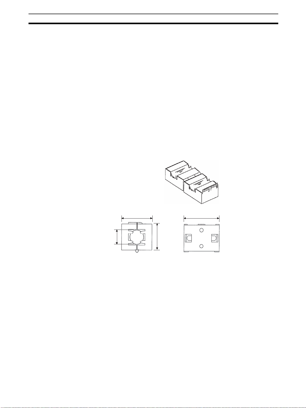
1,2,3... 1. Noise from the communications cable can be reduced by installing a ferrite
core on the communications cable within 10 cm of the DeviceNet Unit.
30 mm
13 mm 29 mm
Ferrite Core (Data Line Filter): 0443-164151 (manufactured by Fair-Rite Products Co., Ltd.)
Impedance specifications
25 MHz: 105
100 MHz: 190 Ω
30 mm
13 mm
29 mm
33 mm
2. Wire the control panel with as thick and short electric lines as possible and
ground to 100
3. Keep DeviceNet communications cables as shor t as pos sible and ground
to 100
Ω
Ω min.
Ω min.
33 mm
xv

EC Directives 6
xvi

SECTION 1
Overview
This section introduces the features and system configuration of the E5ZN-DRT DeviceNet Communications Unit, the
types of E5ZN Temperature Controller that can be used, and other basic information.
1-1 Features and System Configuration . . . . . . . . . . . . . . . . . . . . . . . . . . . . . . . . 2
1-1-1 Features. . . . . . . . . . . . . . . . . . . . . . . . . . . . . . . . . . . . . . . . . . . . . . . 2
1-1-2 Overview of Unit Communications Functions. . . . . . . . . . . . . . . . . 4
1-1-3 System Configuration. . . . . . . . . . . . . . . . . . . . . . . . . . . . . . . . . . . . 7
1-2 Specifications . . . . . . . . . . . . . . . . . . . . . . . . . . . . . . . . . . . . . . . . . . . . . . . . . 9
1-2-1 DeviceNet Communications Specifications . . . . . . . . . . . . . . . . . . . 9
1-2-2 Function and Performance Specifications . . . . . . . . . . . . . . . . . . . . 10
1-2-3 General Specifications . . . . . . . . . . . . . . . . . . . . . . . . . . . . . . . . . . . 11
1-3 Connecting Temperature Controllers . . . . . . . . . . . . . . . . . . . . . . . . . . . . . . . 11
1-3-1 Temperature Controller ID and Number of Connectable Units . . . . 11
1-3-2 Temperature Controller Communications . . . . . . . . . . . . . . . . . . . . 12
1-3-3 Temperature Controller Models . . . . . . . . . . . . . . . . . . . . . . . . . . . . 12
1-3-4 Temperature Controller Power Supply. . . . . . . . . . . . . . . . . . . . . . . 12
1-3-5 Temperature Controller Registration . . . . . . . . . . . . . . . . . . . . . . . . 13
1-4 Initial Temperature Controller Settings. . . . . . . . . . . . . . . . . . . . . . . . . . . . . . 13
1

Features and System Configuration Section 1-1
1-1 Features and System Configuration
1-1-1 Features
The DeviceNet Communications Unit enables a DeviceNet master to communicate with multiple E5 ZN Temperature Controllers throu gh the DeviceNet to
monitor their process values, write parameters, and control operation.
Using DeviceNet Functions
Simultaneously Managing
Multiple Temperature
Controllers from the
Master
Remote I/O
Communications
Explicit Message
Communications
Up to 16 Temperature Controllers can be connected to a single DeviceNet
Communications Unit. The DeviceNet Communications Unit is connected to
the master as a DeviceNet slave. Up to 63 slaves can be connected to a single master, so multiple DeviceNet Communic ations Units and othe r types of
slaves can be managed as part of the same system.
The master and DeviceNet Communications Units can share I/O by using
remote I/O communications. Data in the E5 ZN Temperature Contr ollers, such
as process values (PVs) a nd set poi nts (S Ps), c an be al loca ted for communications with the master to enable sending and receiving the allocated data via
remote I/O communications, without requiring special programming.
• Remote I/O Communications without a Configurator
Using the DeviceNet Communicatio ns Un it, bas ic Temperature Controller
data can be allocate d for communications with the master, such as process values (PVs) and set poin ts (SPs), without re quiring a Confi gurator.
This is called “si mple I/O allocation.” Simple I/O allocation c an be easily
set from the DIP switch on the rear of the DeviceNet Communications
Unit.
• User-set Data Allocations with a Configurator
The specific data req uired for communications with the mas ter can also
be allocated by using I/O allocations from the Configurator.
By executing commands from th e PLC, various o perat io ns can be performed,
including reading/writing specific parameters, such as reading process values
or writing set po ints, and performing operations using o peration commands.
CompoWay/F communications commands can also be executed using explicit
message communications.
Setting, Monitoring, and
Operating the
Temperature Controller
from the Configurator
Automatically Detects
Baud Rate
2
The Configurator can be used to create the device parameters for the
DeviceNet Communications Unit , including settings for the DeviceNet Communications Unit and setti ng for the Temperature Controllers. The Config urator can then be used t o download the parameters tog ether to the DeviceNet
Communications Unit and Temperature Controllers. (See note.)
The Configurator can also be used to monitor Temperature Controller process
values, and execute operation commands for the Temperature Controllers.
The Configurator can be used to copy parameters between Temperature Controller channels, allowing the initial parameters of Temperature Controllers
requiring the same or similar parameters to be easily set.
Previously, the baud rate had to be set for each slave, but the DeviceNet Communications Unit automatically detects and matches the baud rate of the master, so this setting is not required. (If the ma ster's baud rate is changed, turn
OFF the communications power supply to the DeviceNet Communications
Unit and then turn it ON again.)

Features and System Configuration Section 1-1
Wide Range of
Copy Function (Uploading
or Downloading
Temperature Controller
Parameters)
Monitoring Network P ower
Voltage
Monitoring the Unit
Conduction Time
Unit Comments Any name can be set for a DeviceNet Communications Unit and recorded in
Setting Temperature
Controller Comments
Maintenance Functions
Parameters for all Temperature Controllers connec ted to the DeviceNet Communications Unit can be upl oaded or downloaded togeth er. (The parameters
that have been read are stored in the DeviceNet Communications Unit.) When
Temperature Controllers are replaced, the new Controllers can be easily reset
onsite without using a Configurator.
The DeviceNet network communications power voltage values (present value,
peak value, and bottom value) can be stored in the DeviceNet Communications Unit, and the rec orded voltages can be read fro m the Configurator. By
setting the voltage monitor value in the DeviceNet Communications Unit, notification will be sent to the master if the voltage level drops below the monitor
value.
The conduction time of th e DeviceNet Communications Unit ’s internal circuit
power supply can be r ecorded. The recorded conductio n time can be read
from the Configurator or us ing explicit messages. By sett ing a monitor value
for the conduction time in the DeviceNet Communications Unit, notification will
be sent to the master when the total time exceeds the monitor value.
the Unit. Specifying names enables the user to easily differentiate the applications of the DeviceNet Communications Units when setting and monitoring
them from the Configurator.
A name can be set for each Temperature Controll er cha nne l c onne ct ed to th e
DeviceNet Communications Unit and rec orded in th e DeviceNet Communic ations Unit. Specifying na mes enables the u ser to easily differentiate the function of each channel when setting and monitoring them from the Configurator.
Monitoring
Communications Error
History
Monitoring Temperature
Controller P ower Status
Monitor Temperature
Controller Conduction
Time and RUN Time
Easy Expansion
Connecting Existing
Terminal Units
Internal Circuit Power
Supply for Slaves Not
Required
The error status for the last four communications errors (the causes and communications power voltage when the communicatio ns error occurred) can be
recorded in the D eviceNet Communications Unit. The recorded communications error history can be read from the Configurator.
The power supply to the Temperature Contr ollers can monitored to confirm
that power is ON and send notification of the status to the master. (The power
status can be checked for Temperature Controllers connected to the
DeviceNet Communications Unit only.) The power status of the Temperature
Controllers can be read from the Configurator or using explicit messages.
The conduction time of the Temperature Controller’s internal circuit power
supply or the RUN time of the Temperature Controller can be totaled and
recorded. (Select whet her to total the co nducti on tim e or RUN time by setting
the monitor mode.) The recorded total tim e can be read using the Config urator or explicit messages. By setting a monitor value in the DeviceNet Communications Unit, notification will be sent to the master if the Unit conduction time
exceeds the monitor value.
DeviceNet Communications Units can be connected to the Terminal Units
used for previous (non-DeviceNet) E5ZN Temperature Controllers, so existing
Temperature Controllers can easily be connected to DeviceNet.
The internal circui t power of the DeviceNet Communications Unit is supplie d
from the DeviceNet communications power supply. Therefore, power supply
wiring is not req uir ed for the DeviceNet Co mmunications Unit. (The Temperature Controller power supply must be supplied separately.)
3
Features and System Configuration Section 1-1
1-1-2 Overview of Unit Communications Functions
Remote I/O
Communications
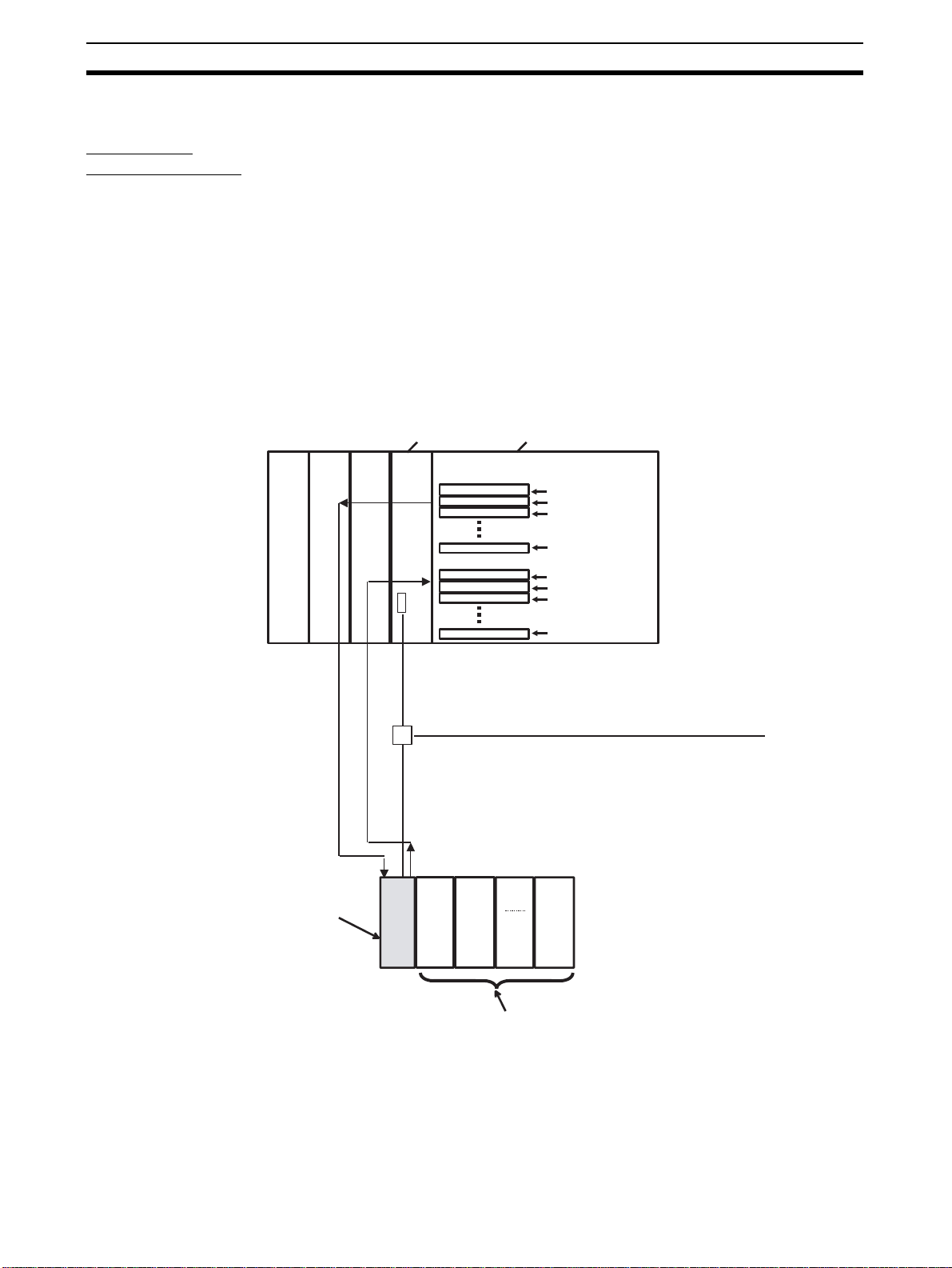
DeviceNet Communications Unit data is shared with the master’s IN Area and
OUT Area through DeviceNet. Up to 100 words (200 bytes) each can be used
as the IN Area and OUT Area for the DeviceNet Communications Unit. (Th e
first two words (four bytes) of the OUT Area are always allocated as Outpu t
Enable Bits).
The IN Area is a llocated for data such as the co mmunicatio ns status and the
process values of the Temperature Control ler channels and th e OUT Area is
allocated for the set points of the channels and other data.
When using a CS/CJ-series DeviceNet Unit as the master, the IN Area can be
divided into two areas. One is normally used for input data (such as Temperature Controller p rocess values), a nd the ot her can be used for rea ding st atus
(such as Temperature Controller s tatus). Even when the IN Area is divided
into two areas, however, the total number of words that can be used for the IN
Area is still 100 words (200 bytes).
DeviceNet Unit
Remote I/O communications
output area
Input Area
CPU Unit
Unit 0, Ch 1 SP
Unit 0, Ch 2 SP
Unit 1, Ch 1 SP
Unit 15, Ch 2 PV
Unit 0, Ch 1 PV
Unit 0, Ch 2 PV
Unit 1, Ch 1 PV
PLC
Remote I/O
communications
E5ZN-DRT
DeviceNet Communications Unit
Unit 0 Unit 1
Unit 15, Ch 2 PV
DeviceNet
Unit
15
E5ZN Temperature Controllers
4
Features and System Configuration Section 1-1
p
Explicit Message
Communications
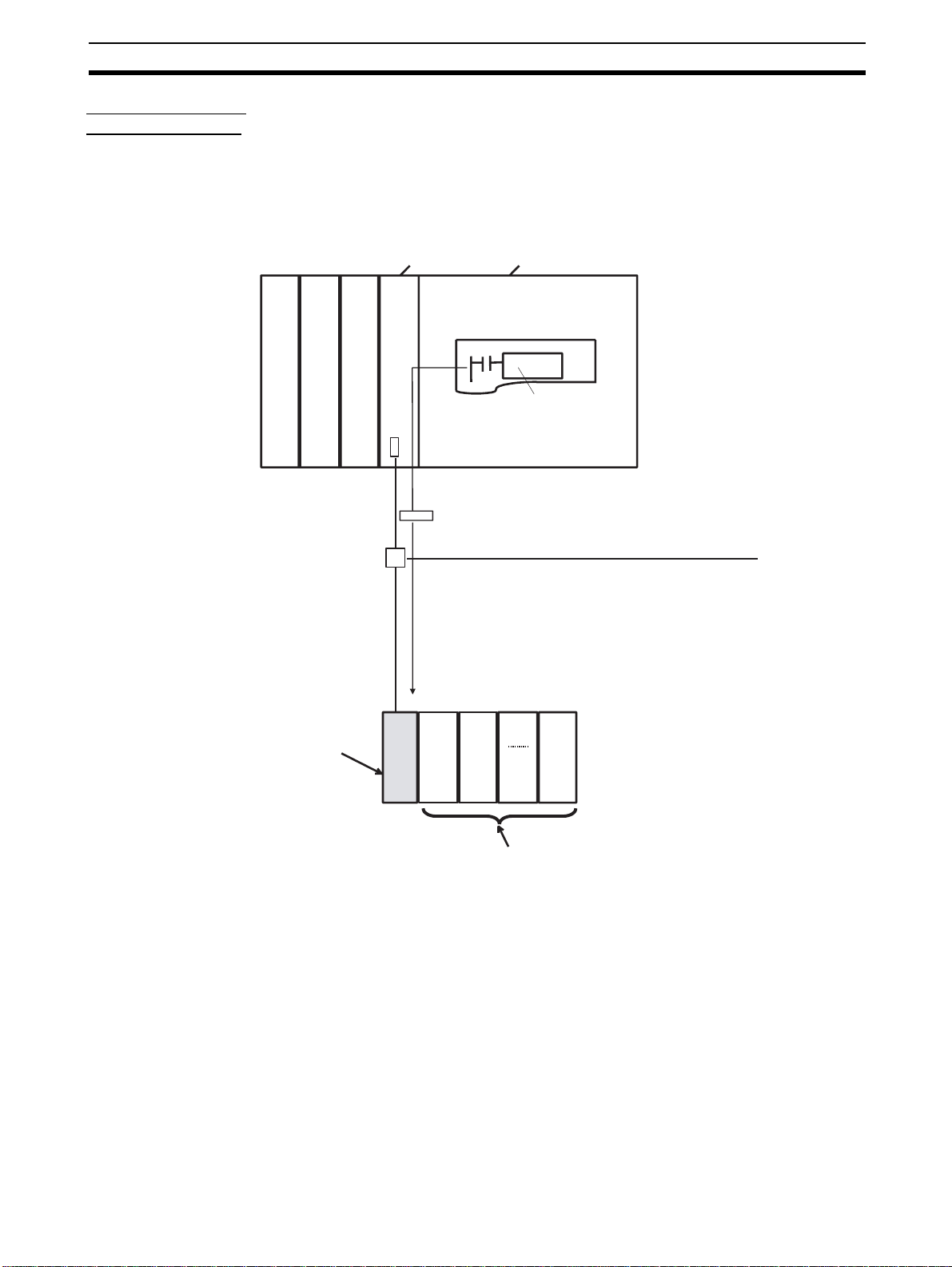
Explicit message commands can be sent from the m aster to the DeviceNet
Communications Unit to read or wr ite the parameters of the con nected Temperature Controllers. CompoWay/F communications commands that were
previously used for Temperature Controll ers c an also be sent (in explicit me ssage format).
The DeviceNet Communications Unit’s own parameters can also be read or
written.
DeviceNet Unit CPU Unit
PLC
Ladder program
CMND or other
communications
instruction
Explicit message communications
DeviceNet
E5ZN-DRT
DeviceNet Communications Unit
Unit 0 Unit 1
E5ZN Tem
Unit
15
erature Controllers
5
Features and System Configuration Section 1-1
Transferring,
Monitoring, and
Operating from the
Configurator
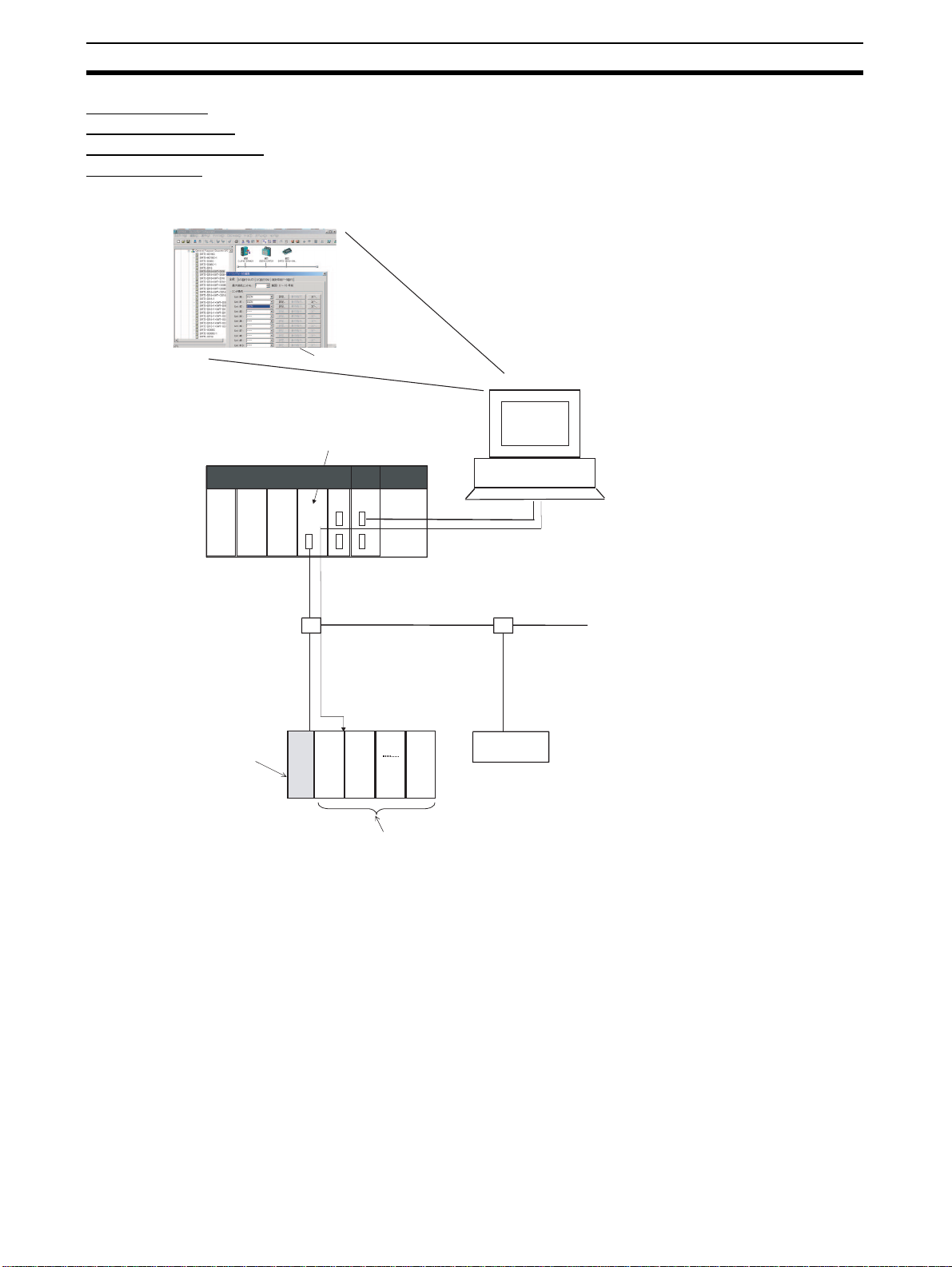
Any of the Temperature Controller parameter s can be read or wr itten from a
personal computer usin g the Confi gurator ( Ver. 2.31 or later), and then saved
as a file.
The setup parameters for each Temperature C ontroller channel can be copied, allowing the same or si milar s ettings to be eas ily se t for multiple Temperature Controllers.
DeviceNet Configurator
E5ZN Temperature Controller
CS/CJ-series DeviceNet Unit
PLC
Serial connection
Setting, monitoring, and executing operation commands for the
Temperature Controllers using the Configurator.
• Setting Temperature Controller settings and downloading them.
• Monitoring Temperature Controller process values and target values.
• Executing Temperature Controller operation commands.
DeviceNet
E5ZN-DRT
DeviceNet Communications Unit
Unit 0Unit
1
Unit
15
E5ZN Temperature Controllers
DeviceNet Slave
6
Features and System Configuration Section 1-1
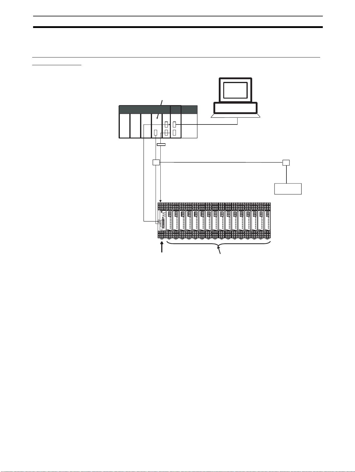
1-1-3 System Configuration
The DeviceNet Communications Unit and Temperature Controllers are configured as
a single block.
DeviceNet Configurator
CS/CJ-series DeviceNet Unit
PLC
Serial connection
(setting, monitoring, and operating)
Explicit messages
DeviceNet
DeviceNet slave
UNIT
UNIT
UNIT
UNIT
UNIT
UNIT
UNIT
UNIT
UNIT
BPS
BPS
BPS
POWER
POWER
POWER
ERROR
ERROR
ERROR
SD/RD
SD/RD
SD/RD
OUT1
OUT1
OUT1
OUT2
OUT2
OUT2
SUB1
SUB1
SUB1
SUB2
SUB2
SUB2
E5ZN
E5ZN
E5ZN
UNIT
BPS
BPS
BPS
POWER
POWER
POWER
ERROR
ERROR
ERROR
SD/RD
SD/RD
SD/RD
OUT1
OUT1
OUT1
OUT2
OUT2
OUT2
SUB1
SUB1
SUB1
SUB2
SUB2
SUB2
E5ZN
E5ZN
E5ZN
E5ZN
E5ZN-DRT
DeviceNet Communications Unit
UNIT
UNIT
BPS
BPS
BPS
POWER
POWER
POWER
ERROR
ERROR
ERROR
SD/RD
SD/RD
SD/RD
OUT1
OUT1
OUT1
OUT2
OUT2
OUT2
SUB1
SUB1
SUB1
SUB2
SUB2
SUB2
E5ZN
E5ZN
UNIT
BPS
BPS
BPS
POWER
POWER
POWER
ERROR
ERROR
ERROR
SD/RD
SD/RD
SD/RD
OUT1
OUT1
OUT1
OUT2
OUT2
OUT2
SUB1
SUB1
SUB1
SUB2
SUB2
SUB2
E5ZN
E5ZN
E5ZN
E5ZN Temperature Controllers
(up to 16 Controllers)
UNIT
UNIT
BPS
POWER
ERROR
SD/RD
OUT1
OUT2
SUB1
SUB2
E5ZN
UNIT
BPS
BPS
BPS
POWER
POWER
POWER
ERROR
ERROR
ERROR
SD/RD
SD/RD
SD/RD
OUT1
OUT1
OUT1
OUT2
OUT2
OUT2
SUB1
SUB1
SUB1
SUB2
SUB2
SUB2
E5ZN
E5ZN
E5ZN
E5ZN
Connect the master to the DeviceNet Communicati ons Unit, and connect the
DeviceNet Communications Unit to the Temp erature Controllers through the
Terminal Units.
The DeviceNet Communications Unit and Temperature Controllers can be
connected without using RS-485 communications cable.
The DeviceNet Communications Unit shares I/O with the master as a
DeviceNet slave, and can send data to and receive data from the master
using explicit messages.
Up to 63 slaves can be connecte d to a single master. Up to 16 Temperature
Controllers can be connected to a single DeviceNet Communications Unit.
Note Always connect the DeviceNet Communications Unit to the E5ZN-SCT24S
Terminal Unit on the left end of the block.
7
Features and System Configuration Section 1-1
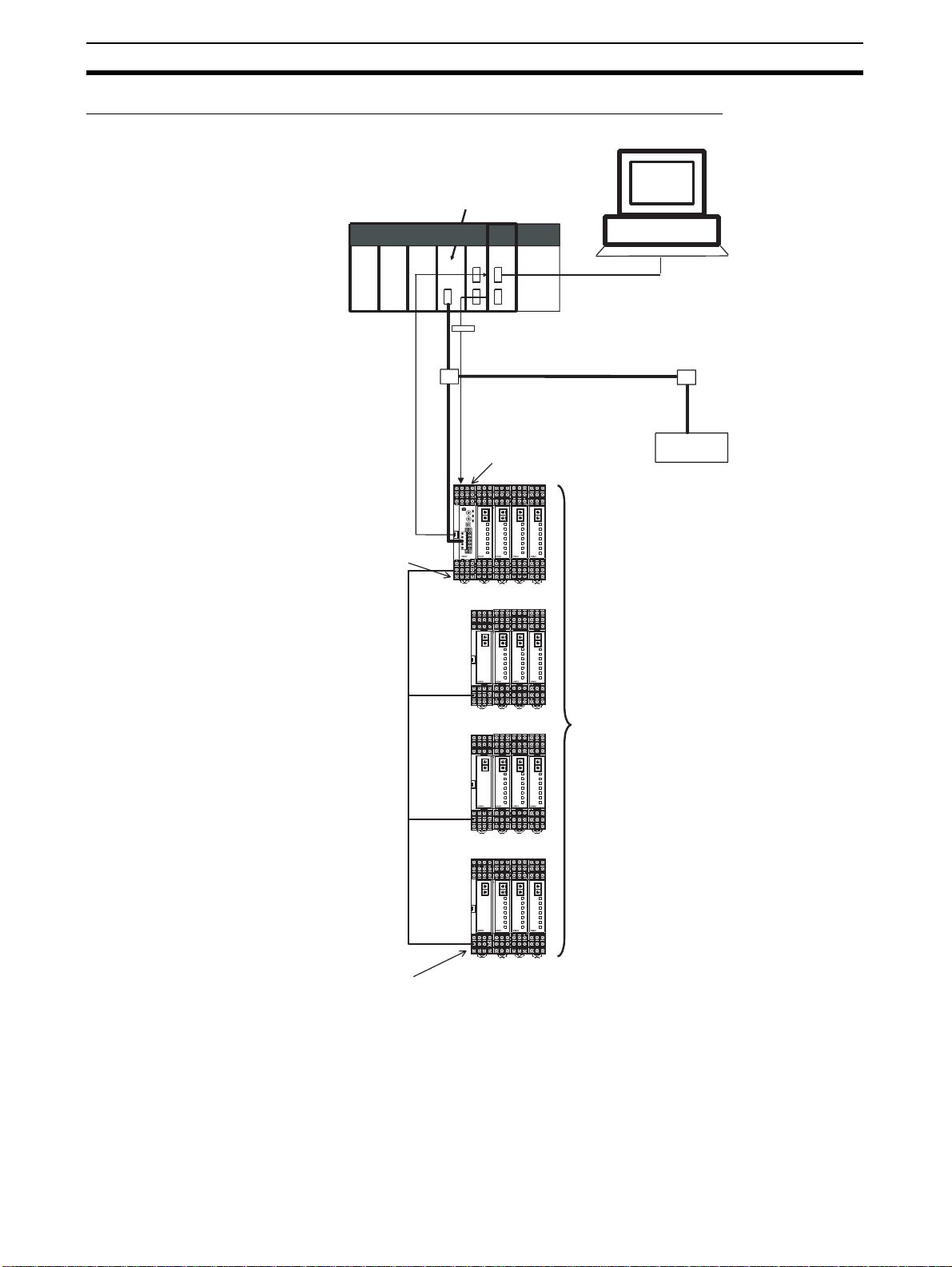
Multiblock Configuration Using
Terminating resistance of 100 to 125 Ω
(1/2 W) connected to both ends of the
RS-485 transmission path
RS-485 Communications Connections
DeviceNet Configurator
CS/CJ-series DeviceNet Unit
PLC
Serial connection
(setting, monitoring, and operating)
Explicit messages
DeviceNet
E5ZN-DRT
DeviceNet Communications Unit
DeviceNet slave
UNIT
UNIT
UNIT
BPS
POWER
ERROR
SD/RD
OUT1
OUT2
SUB1
SUB2
E5ZN
UNIT
BPS
BPS
BPS
POWER
POWER
POWER
ERROR
ERROR
ERROR
SD/RD
SD/RD
SD/RD
OUT1
OUT1
OUT1
OUT2
OUT2
OUT2
SUB1
SUB1
SUB1
SUB2
SUB2
SUB2
E5ZN
E5ZN
E5ZN
E5ZN
RS-485 communications cable
(length: 500 m max.)
Terminating resistance of 100 to 125 Ω
(1/2 W) connected to both ends of the
RS-485 transmission path
Connect the master and DeviceNet Communic ations Unit, and then u se RS485 communications to connect the Temperature Controllers divided into multiple blocks. Connect the DeviceNet Communications Unit to any one of the
blocks. Connect each block with the Terminal Unit on the end.
The total cable length for RS-485 communication s can be up to 500 m, so
Temperature Controllers locate d a t a di s tanc e ca n be ope rated usin g a s i ngl e
DeviceNet Communications Unit.
UNIT
UNIT
UNIT
BPS
POWER
ERROR
SD/RD
OUT1
OUT2
SUB1
SUB2
UNIT
BPS
BPS
BPS
POWER
POWER
POWER
ERROR
ERROR
ERROR
SD/RD
SD/RD
SD/RD
OUT1
OUT1
OUT1
OUT2
OUT2
OUT2
SUB1
SUB1
SUB1
SUB2
SUB2
SUB2
E5ZN
E5ZN
E5ZN
E5ZN
E5ZN Temperature Controllers
(up to 16 Controllers)
UNIT
UNIT
UNIT
BPS
POWER
ERROR
SD/RD
OUT1
OUT2
SUB1
SUB2
UNIT
BPS
POWER
ERROR
SD/RD
OUT1
OUT2
SUB1
SUB2
UNIT
BPS
BPS
BPS
POWER
POWER
POWER
ERROR
ERROR
ERROR
SD/RD
SD/RD
SD/RD
OUT1
OUT1
OUT1
OUT2
OUT2
OUT2
SUB1
SUB1
SUB1
SUB2
SUB2
SUB2
E5ZN
E5ZN
E5ZN
E5ZN
UNIT
UNIT
UNIT
BPS
BPS
BPS
POWER
POWER
POWER
ERROR
ERROR
ERROR
SD/RD
SD/RD
SD/RD
OUT1
OUT1
OUT1
OUT2
OUT2
OUT2
SUB1
SUB1
SUB1
SUB2
SUB2
SUB2
E5ZN
E5ZN
E5ZN
E5ZN
8

Specifications Section 1-2
Up to 63 slaves can be connecte d to a single master. Up to 16 Temperature
Controllers total for all blocks can be connected to a sing le DeviceNet Communications Unit.
Terminating resistance of 100 to 125
Ω (1/2 W) must be connec ted to both
ends of the RS-485 communications transmission path. For details on RS-485
communications with Temperature Controllers, refer to the E5ZN Temperature
Controller Operation Manual (H113).
Note Connect the DeviceNet Communica tions Unit to th e E5ZN-SCT24S Terminal
Unit on the left end of any one of the blocks.
1-2 Specifications
1-2-1 DeviceNet Communications Specifications
Item Specifications
Communicati ons protocol Conforms to DeviceNet
Communications
functions
Connection format Combination of multidrop and T-branch connections (for trunk and drop lines)
Baud rate DeviceNet: 500, 250, or 125 kbps, or automatic detection of master baud rate
Communications media Special 5-wire cable (2 signal lines, 2 power lines, and 1 shield line)
Remote I/O communications
Simple I/O allocation
I/O allocations
from the Configurator
Message communications
Setting, monitoring
and controlling
operations from
the Configurator
• Master-slave connections (polling, bit-strobe, COS, or cyclic)
• Conform to DeviceNet specifications.
• Allocates I/O data using switch settings only, without a Configurator.
• I/O is allocated for Temperature Controller status es , process v alues , se t points ,
alarm output status, and other basic data only.
• One block for IN area, up to 46 words (words are allocated through the maximum number of units connected)
• One block f o r O UT are a, u p to 38 w o rds (words are allocated through t he m ax imum number of units connected)
• Can be used to allocate any I/O data from the Configurator.
• Can be used to allocate any data, such as parameters specific to the
DeviceNe t Comm unicati ons U nit and th e Temperature Controller va riabl e area.
• Up to 2 blocks for the IN area, up to a total of 100 words. (See note 1.)
• One block for OUT area 1 block, up to 100 words (first two words are always
allocated to Output Enable Bits). (See note 2.)
• Explicit message communications
• CompoWay/F communications commands can be sent (commands are sent in
explicit message format).
Supported by DeviceNet Configurator (using the Edit Parameters and Device
Monitor functions of the DeviceNet Communications Unit and Temperature Controllers).
• Used to set and monitor the DeviceNet Communications Unit.
• Used to register connection configurations, make initial settings (see note 3),
change settings, and monitor the Temperature Controllers.
• Use to allocates data for master communications.
• Used to allocates word in the IN and OUT Areas for specific data.
• Used to sends operation commands to the Temperature Controllers.
RS-485: 38.4 kbps
9

Specifications Section 1-2
Item Specifications
Communications distance Baud rate Network length Drop line length Total drop line
500 kbps 100 m max.
250 kbps 250 m max.
125 kbps 500 m max.
The values in parentheses apply when Thin Cables are used.
Communications power supply 11 to 25 VDC
Maximum numb er of nodes tha t can be
connected
Maximum number of slaves that can be
connected
Error control CRC error detection
Power supply Power supplied from DeviceNet communications connector (DeviceNet commu-
64 (includes Configurator when used.)
63
nications power supply and DeviceNet Communications Unit internal circuit
power supply)
(100 m max.)
(100 m max.)
(100 m max.)
6 m max. 39 m max.
6 m max. 78 m max.
6 m max. 156 m max.
Note 1. When a CS/CJ-series DeviceNet Unit is used as the ma ster, two blocks
can be used for the IN Area (the connect ions can also be set). When a
CVM1, CV-series, or C200HX/HG/HE DeviceNet Master Unit is used, th e
IN Area must be in 1 block, and up to 100 words (200 bytes) are allocated.
(Only polling connections can be used.)
2. When a CVM1, CV-series, or C200HX/HG/HE DeviceNet Mast er Unit is
used, up to 32 words can be allocated in the master for a single node.
3. The set points, alarm setting values, PID constants, and other Temperature Controller parameters can be set together.
length
1-2-2 Function and Performance Specifications
Item Specifications
Maximum number of Temperature
Controllers that can be connected
Applicable Temperature Controllers
Pow e r supply Pow er suppli ed from Terminal Unit terminal block (terminals 19 and 20) (Com mun ica-
Copying The parameters of the connected T emperature Controllers can be uploaded or down-
16
• E5ZN-2QNH03TC-FLK
• E5ZN-2QPH03TC-FLK
• E5ZN-2TNH03TC-FLK
• E5ZN-2TPH03TC-FLK
• E5ZN-2CNF03TC-FLK
• E5ZN-2CPF03TC-FLK
tions power supply between DeviceNet Communications Unit and Temperature Controller, and internal circuit power supply of Temperature Controller)
loaded as a batch, merely by manipulating the DIP switch on the front panel of the
DeviceNet Communications Unit.
The uploaded parameters are stored in the DeviceNet Communications Unit.
• E5ZN-2QNH03P-FLK
• E5ZN-2QPH03P-FLK
• E5ZN-2TNH03P-FLK
• E5ZN-2TPH03P-FLK
• E5ZN-2CNF03P-FLK
• E5ZN-2CPF03P-FLK
10
Connecting Temperature Controllers Section 1-3
1-2-3 General Specifications
Item Specifications
Supply voltage DeviceNet power
supply
External input powe r
supply
Allowab le voltage
range
DeviceNet power
supply
External input powe r
supply
Current consumption DeviceNet power
supply
External input powe r
supply
Vibration resistanc e
Shock resistance
Dielectric strength 500 VAC 50 or 60 Hz 1min between DIN Track and entire terminal block
Insulatio n resistance 20 MΩ min. (at 100 VDC)
Ambient temperature −10 to 55°C (with no condensation or icing)
Ambient humidity 25% to 85%
Storage temperature −25 to 65°C (with no condensation or icing)
Enclosure rating IP00
Dimensions 30 × 130 × 89.6 mm (W × D × H)
Memory protection EEPROM, 100,000 write operations (backup data)
Weight 100 g max. (not including Terminal Unit)
24 VDC (internal circuit)
24 VDC (for RS-485 communications circuit/ Temperature Controllers)
11 to 25 VDC
20.4 to 26.4 VDC
45 mA max. (24 VDC: Current co nsumption of DeviceNet Communications
Unit)
20 mA max. (24 VDC) (See note.)
2
10 to 55 Hz, 10m/s
2
150m/s
max. 3 times each in 3 axes, 6 directions
for 2 hours each in X, Y, and Z directions
(DeviceNet connector) or between DIN Track and all terminals (terminal
sockets)
(When connected to an E5ZN-SCT24S Terminal Unit.)
Note Current supplied to the Temperature Controllers is not included.
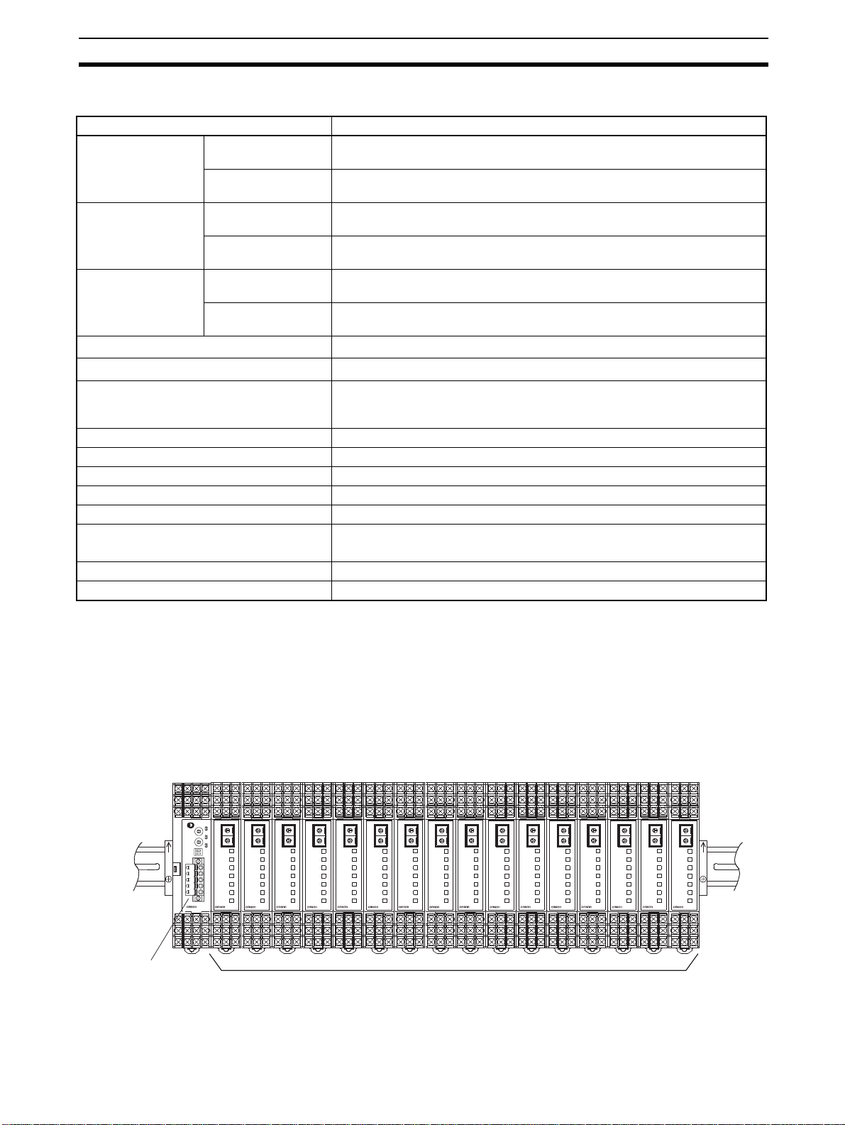
1-3 Connecting Temperature Controllers
1-3-1 Temperature Controller ID and Number of Connectable Units
The Temperature Controllers a re connected alongside the DeviceNet Communications Unit and the block is linked through the Terminal Units connected
to the back of the Temperature Controllers, as shown in the following diagram.
Up
DeviceNet
Communications Unit
UNIT
BPS
POWER
ERROR
SD/RD
OUT1
OUT2
SUB1
SUB2
E5ZN
E5ZN
UNIT
BPS
POWER
ERROR
SD/RD
OUT1
OUT2
SUB1
SUB2
UNIT
BPS
POWER
ERROR
SD/RD
OUT1
OUT2
SUB1
SUB2
E5ZN
E5ZN
UNIT
BPS
POWER
ERROR
SD/RD
UNIT
BPS
POWER
ERROR
SD/RD
OUT1
OUT1
OUT2
OUT2
SUB1
SUB1
SUB2
SUB2
E5ZN
E5ZN
UNIT
BPS
POWER
ERROR
SD/RD
OUT1
OUT2
SUB1
SUB2
UNIT
BPS
POWER
ERROR
SD/RD
OUT1
OUT2
SUB1
SUB2
E5ZN
E5ZN
UNIT
BPS
POWER
ERROR
SD/RD
OUT1
OUT2
SUB1
SUB2
UNIT
BPS
POWER
ERROR
SD/RD
OUT1
OUT2
SUB1
SUB2
E5ZN
E5ZN
UNIT
BPS
POWER
ERROR
SD/RD
UNIT
BPS
POWER
ERROR
SD/RD
OUT1
OUT1
OUT2
OUT2
SUB1
SUB1
SUB2
SUB2
E5ZN
E5ZN
UNIT
BPS
POWER
ERROR
SD/RD
OUT1
OUT2
SUB1
SUB2
UNIT
BPS
POWER
ERROR
SD/RD
OUT1
OUT2
SUB1
SUB2
E5ZN
E5ZN
UNIT
BPS
POWER
ERROR
SD/RD
OUT1
OUT2
SUB1
SUB2
UNIT
UNIT
BPS
BPS
POWER
POWER
ERROR
ERROR
SD/RD
SD/RD
OUT1
OUT1
OUT2
OUT2
SUB1
SUB1
SUB2
SUB2
E5ZN
E5ZN
E5ZN Temperature Controllers
The DeviceNet Communications Unit differentiates each of the connected
Temperature Controllers accordi ng to uni t number s (0 to F) . The Temperature
Up
E5ZN
11

Connecting Temperature Controllers Section 1-3
Controllers can be connected in any order. The unit number of each T emperature Controller is s et using the upper rotar y switch on the front panel o f the
Temperature Controller. Always set a unique unit numb er for each Temperature Controller.
Up to 16 Temperature Controllers can be connected to a single DeviceNet
Communications Unit. RS-48 5 connections also support up to 16 Temperature Controllers.
The E5ZN-SDL Setting Display Unit for E5ZN Temperature Controllers can be
connected at the same time.
Note There is no priori ty between operation commands and s ettings for DeviceNet
communications from the ma ster or Configurator, and operation commands
and settings from the S etting Display Unit. Do not change the same dat a or
send different operation commands more than one source at the same time.
1-3-2 Temperature Controller Communications
The DeviceNet Communications Unit and Temperature Controllers communicate at a baud rate of 38,400 bps. Set the baud rate using the lower rotar y
switch on the front panel of the Temperature Controllers to 3 (= 38,400 bps).
Communications are performed using a transmission format of 7-bit data, 2
stop bits, and 2 parity bits. These are the default settings. If the default values
have been changed, use the E5ZN-SDL Setting Display Unit to return the
Temperature Controller settings to 7-bit data, 2 stop bits, 2 parity bits.
1-3-3 Temperature Controller Models
The DeviceNet Communications Unit can be conn ected to th e following Temperature Controllers.
Model Control output Input type Auxiliary output HB
E5ZN-2QNH03TC-FLK Voltage output (pulse outE5ZN-2QNH03P-FLK Platinum-resistance
E5ZN-2QPH03TC-FLK Thermoc ouple Sour cing (PNP)
E5ZN-2QPH03P-FLK Platinum-resistance
E5ZN-2TNH03TC-FLK Transistor output (pulse
E5ZN-2TNH03P-FLK Platinum-resistance
E5ZN-2TPH03TC-FLK Thermocouple Sourcing (PNP)
E5ZN-2TPH03P-FLK Platinum-resistance
E5ZN-2CNF03TC-FLK Analog output (current
E5ZN-2CNF03P-FLK Platinum-resistance
E5ZN-2CPF03TC-FLK Thermocouple Sourcing (PNP)
E5ZN-2CPF03P-FLK Platinum-resistance
put)
output)
output)
Thermocouple Sinking (NPN) Yes
thermometer
thermometer
Thermocouple Sinking (NPN)
thermometer
thermometer
Thermocouple Sinking (NPN) None
thermometer
thermometer
1-3-4 Temperature Controller Power Supply
Power is supplied to the Temperature Controllers through terminals 19 and 20
of the E5ZN-SCT24S Terminal Units.
12
Initial Temperature Controller Settings Section 1-4
1-3-5 Temperature Controller Registration
The unit numbers of the c onnected Temperature Controllers must be regi stered in the configuration in the DeviceNet Communications Unit. The
DeviceNet Communications Unit autom ati ca ll y veri fie s t hat t he r eg ist ered uni t
numbers match the numbers of the Controllers currently able to communicate.
If the unit numbers do not match in the verification proc ess, the Temperature
Controllers will be determined to have an error, causing the following status.
• The TS indicator will flash red.
• The Communicating Flag will turn OFF and the Communications Error
Flag will turn ON for each Temperature Controll er that is not commun icating but is registered as being c onnected to the DeviceNet Communications Unit.
The following two methods can be used to regis ter the conne ction config uration of the Temperature Controller.
1,2,3... 1. Registering with the Configurator or explicit messages (Turn OFF pin 1 on
the DIP switch on the rear of the DeviceNet Communic ations Unit to enable this method)
2. Registe ring w it h th e r ot a ry switches on th e r ear of the De vi ce Net C o mm u nications Unit (Turn ON pin 1 on the DIP switch on re ar of the DeviceNet
Communications Unit to enable this method.)
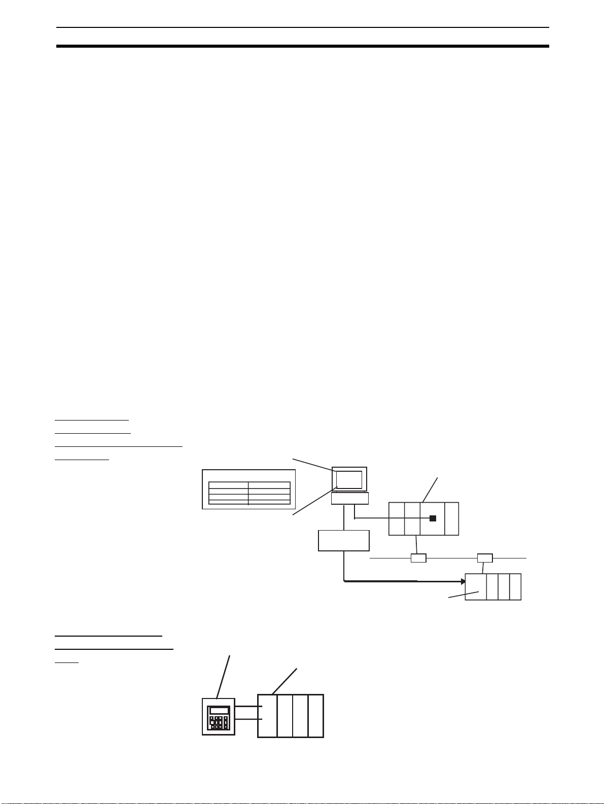
1-4 Initial Temperature Controller Settings
The following four methods are provided for setting the E5ZN Temperature
Controllers.
Transferring
T emperature
Controller P arameters
Together
Setting with E5ZNSDL Setting Display
Unit
Set each of the Temperature Controller parameters in the E dit Device Parameters Window from the DeviceNet Configurator, and then transfer them
together via the DeviceNet network.
Edit device parameters
Edit Unit parameters
Proportional band
Target value
Configurator
Temperature
Controller
parameters
DeviceNet
Communications Unit
Set the parameters from the E5ZN-SDL Setting Display Unit.
E5ZN-SDL Setting Display Unit
Terminal Unit connected to DeviceNet
Communications Unit
CS/CJ-series DeviceNet Unit
PLC
DeviceNet
+
−
13
Initial Temperature Controller Settings Section 1-4
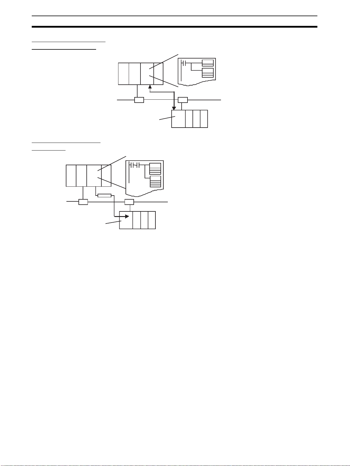
Setting with Remote I/
O Communications
Setting with Explicit
Messages
PLC
Set the parameters from the P LC w ith the ma ste r using remote I/O communications.
PLC
DeviceNet
Communications Unit
SET
(1) Execute a command to shift to setting area 1.
MO V
(2) Set the parameters in variable area C3.
Set the initial settings from the PLC with the ma ster by sending an explicit
message.
(1) Send a command to shift to setting area 1.
CMND
CMND
(Operation command 30 05, command code 07)
(2) Set the parameters in variable area C3.
(VARIABLE AREA WRITE 01 02, variable type C3).
DeviceNet
Communications Unit
14

SECTION 2
Operating Procedures
This section outlines the basic operating procedures of the E5ZN-DRT DeviceNet Communications Unit.
2-1 Setup Procedure . . . . . . . . . . . . . . . . . . . . . . . . . . . . . . . . . . . . . . . . . . . . . . . 16
2-2 Startup Procedure . . . . . . . . . . . . . . . . . . . . . . . . . . . . . . . . . . . . . . . . . . . . . . 17
2-2-1 Simple I/O Allocation. . . . . . . . . . . . . . . . . . . . . . . . . . . . . . . . . . . . 17
2-2-2 I/O Allocation Using the Configurator. . . . . . . . . . . . . . . . . . . . . . . 18
15
 Loading...