

Page 1

CNC SYSTEM
OSP-P300S
MACT
URN
250/350 80/120-TOOL MAGAZINE SPECIFICATION
INSTRUCTION MANUAL
(1st Edition)
Pub No. 6226-E (LE61-621-R1) Feb. 2013
Page 2

6226-E P-(i)
TABLE OF CONTENTS
TABLE OF CONTENTS
SECTION 1 OVERVIEW..............................................................................................1
SECTION 2 MACHINE SPECIFICATIONS..................................................................2
1. Machine Overview ................................................................................................................... 2
1-1. Magazine .......................................................................................................................... 2
1-2. Tool Number..................................................................................................................... 2
2. ATC Operation Overview......................................................................................................... 3
3. ATC Operation Sequence........................................................................................................5
SECTION 3 ATC LOGIC TABLES ...............................................................................8
SECTION 4 DATA SETTING .....................................................................................29
1. ATC Function Display Screen................................................................................................ 29
2. Data Setting Screen............................................................................................................... 31
2-1. Magazine Information List .............................................................................................. 32
2-2. List of not Mounted Tools ............................................................................................... 33
2-3. List of Lack Tools............................................................................................................ 34
2-4. Registering and Attaching a Tool ................................................................................... 34
2-5. Main Magazine Tool Specification.................................................................................. 34
SECTION 5 MANUAL OPERATION ..........................................................................35
1. Manual Magazine Operation.................................................................................................. 35
1-1. Overview......................................................................................................................... 35
1-2. Mechanical Lock.............................................................................................................35
2. Interlock Function for Magazine Door Open/Close Operation ............................................... 36
3. Manual ATC Operation ..........................................................................................................37
SECTION 6 ATC PROGRAM COMMANDS ..............................................................39
1. ATC Commands .................................................................................................................... 40
2. Description of Machining Program......................................................................................... 42
2-1. OSP without Tool Life Management Specification ......................................................... 42
2-2. OSP with Tool Life Management Specification .............................................................. 45
3. ATC Commands and ATC Operation .................................................................................... 48
SECTION 7 PARAMETERS.......................................................................................49
1. ATC Parameter...................................................................................................................... 49
2. Machine System Parameter .................................................................................................. 49
2-1. System Check Mode (Machine System Parameter)....................................................... 49
2-2. ATC (Machine System Parameter)................................................................................. 50
Page 3

6226-E P-(ii)
TABLE OF CONTENTS
SECTION 8 OTHERS ................................................................................................51
1. System Variables................................................................................................................... 51
2. ATC Macro Command ........................................................................................................... 51
2-1. Shutter Operation ...........................................................................................................51
2-2. Flowchart ........................................................................................................................ 52
SECTION 9 ALARM AND ERROR ............................................................................56
Page 4

6226-E P-1
SECTION 1 OVERVIEW
SECTION 1 OVERVIEW
The 80/120-tool magazine specification consists of two types of magazine, main magazine (rotating
magazine) and sub magazine (fixed magazine).
The main magazine is mounted on the saddle, allowing tool change operation at any position on the Z-axis to
reduce tool change time.
Although the main magazine can store only up to 41 tools, tool storage capacity is expanded to 80 or 120
tools by installing the sub magazine. Tools are exchanged between the main magazine and the sub magazine
to handle wide variety of workpiece kinds.
This Operation Manual deals with the 80/120-tool magazine specification of MacTurn. For general information
of the ATC of MacTurn, refer to the following manual.
OSP-P300S MACTURN/MULTUS Series Operation Manual
Page 5

SECTION 2 MACHINE SPECIFICATIONS
SECTION 2 MACHINE SPECIFICATIONS
1. Machine Overview
1-1. Magazine
Two types of magazine capacity are available, 80 tools and 120 tools.
1-2. Tool Number
There are two kinds of command modes for tool preparation commands: TL and TD, which can be
selected in the parameter settings.
The TL command mode is a tool preparation command that has been used with OSP-P200 and
former OSP versions; the TD command mode is a mode used in the tool information management
function that has been added to OSP-P300S. This is the mode that enables tools to be offset by
specifying the posture number which has been registered in the TOOL DATA SETTING screen in
advance.
6226-E P-2
[TD command mode]
Tool numbers between No.1 and No.9999 can be used.
[TL command mode]
Tool numbers between No.1 and No.96 can be used. Or tool numbers between No.1 and No.200
can be used when the number of tool management groups is 200 sets. The same numbers can be
used for the tool offset numbers.
For the details of TL and TD command modes, refer to the operation manual of OSP-P300S
MACTURN/MULTUS series.
Page 6

2. ATC Operation Overview
The illustration below shows the mechanism of the ATC.
(1) ATC
6226-E P-3
SECTION 2 MACHINE SPECIFICATIONS
LE61621R0100400030001
Page 7
SECTION 2 MACHINE SPECIFICATIONS
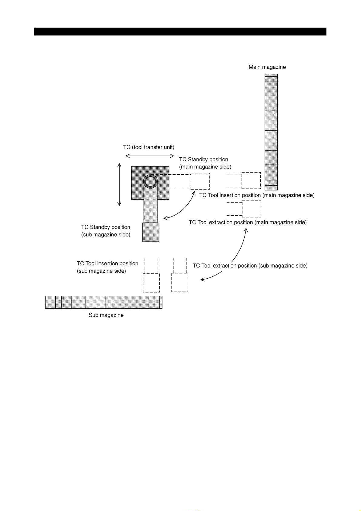
(2) TC (Tool Transfer Unit)
The illustration below shows the top view of the TC (tool transfer unit) and how it operates.
6226-E P-4
LE61621R0100400030002
Page 8

3. ATC Operation Sequence
ATC operation sequence of the 80/120-tool magazine specification is as indicated below.
(Tool change for tools in the main magazine)
* Same ATC operation sequence as 44/30-tool specification magazine
S1 Next tool write/Main MG Search/Sub MG Search
S2 Dummy sequence
S3 Main MG Indexing next tool
S4 RS Insertion
S5 RS Tool change position
S6 RS Extraction/Shutter 2 close
S7 Waiting for completion of machining
S8 Main MG Starting indexing of tool storing pot (Turret)
S9 Shutter open
S10 EA Tool change
S11 Shutter close
6226-E P-5
SECTION 2 MACHINE SPECIFICATIONS
S12 Main MG Tool storing pot indexed (RS)
S13 RS Insertion/Shutter 2 open
S14 RS MG position
S15 RS Extraction
Abbreviation:
MG : Magazine
RS : Ready station
EA : Tool change arm
Page 9

SECTION 2 MACHINE SPECIFICATIONS
(Tool change for sub magazine tools)
S22 Sub MG Indexing the next tool/Main MG TC Indexing the empty pot
S23 TC Tool insertion position (Sub MG side)
S24 TC Tool extraction position (Sub MG side)
S25 Waiting for completion of machining
S26 Main MG TC Empty pot indexing confirmation
S27 TC Turn to the main MG side
S28 Dummy sequence
S29 TC Tool insertion position (Main MG side)
S30 TC Standby position (Main MG side)
S31 TC Turn to the sub MG side/Main MG Indexing the tool mounting pot
S32 RS Insertion
S33 RS Tool change position
S34 RS Extraction/Shutter 2 close
S35 Dummy sequence
S36 Shutter open/Main indexing
S37 EA Tool change
S38 Shutter close
6226-E P-6
S39 Main MG Tool mounting pot indexed
S40 RS Insertion/Shutter 2 open
S41 RS MG position
S42 RS Extraction
S43 Main MG TC Indexing the tool mounting pot/Sub MG Indexing the empty pot/TC Turn to
main MG side
S44 TC Tool insertion position (Main MG side)
S45 TC Tool extraction position (Main MG side)
S46 Sub MG Empty pot indexing confirmation
S47 TC Turn to sub MG side
S48 Dummy sequence
S49 TC Tool insertion position (Sub MG side)
S50 TC Standby position (Sub MG side)
Abbreviation:
MG : Magazine
TC : Tool transfer unit (transfers a tool between sub magazine and main magazine)
RS : Ready station
EA : Tool change arm
Page 10

6226-E P-7
SECTION 2 MACHINE SPECIFICATIONS
(Tool movements)
S61 Main MG Empty pot search
S62 Main MG Indexing the return tool to TC position/Sub MG Indexing the empty pot/TC Turn
to main MG side
S63 TC Tool insertion position (Main MG side)
S64 TC tool extraction position (Main MG side)
S65 Sub MG Confirming indexing of the empty pot
S66 TC Turn to the sub MG side
S67 Dummy sequence
S68 TC Tool insertion position (Sub MG side)
S69 TC Standby position (Sub MG side)
S70 Sub MG Indexing the next tool/Main MG TC Indexing the empty pot
S71 TC Tool insertion position (Sub MG side)
S72 TC Tool extraction position (Sub MG side)
S73 Main MG TC Confirming indexing of the empty pot
S74 TC Turn to the main MG side
S75 Dummy sequence
S76 TC tool insertion position (Main MG side)
S77 TC Standby position (Main MG side)
S78 TC Turn to the sub MG side
S81 Dummy sequence
S82 Main MG TC Indexing the next tool/Sub MG Indexing the empty pot/TC Turn to the main
MG side
S83 TC Tool insertion position (Main MG side)
S84 TC Tool extraction position (Main MG side)
S85 Sub MG Confirming the indexing of the empty pot
S86 TC Turn to the sub MG side
S87 Dummy sequence
S88 TC Tool insertion position (Sub MG side)
S89 TC Standby position (Sub MG side)
Abbreviation:
MG : Magazine
TC : Tool transfer unit (transfers a tool between sub magazine and main magazine)
RS : Ready station
EA : Tool change arm
Page 11

6226-E P-8
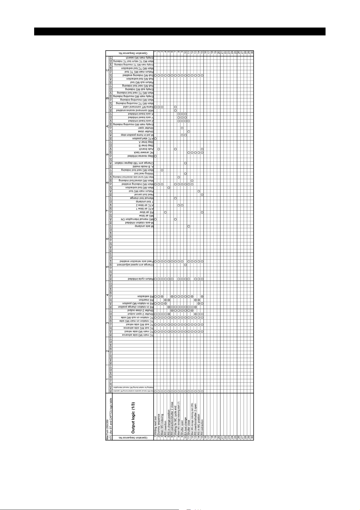
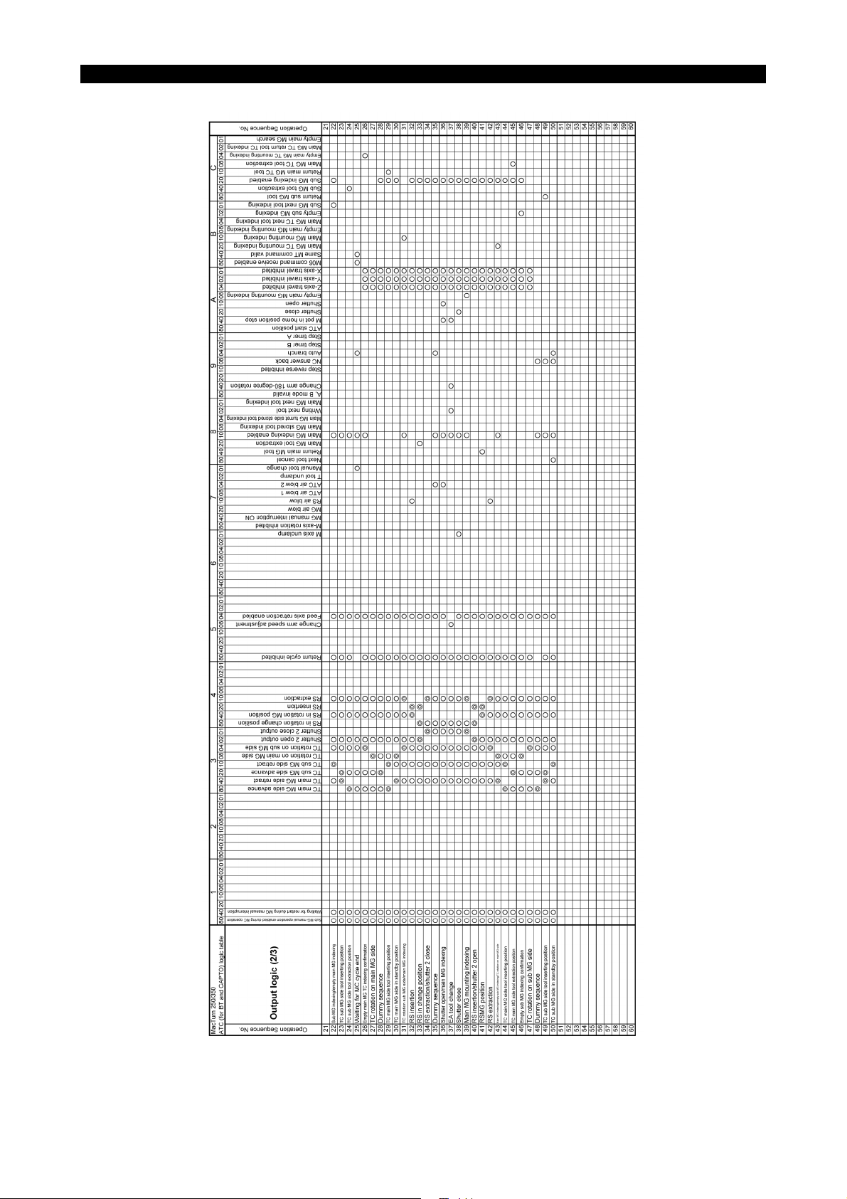
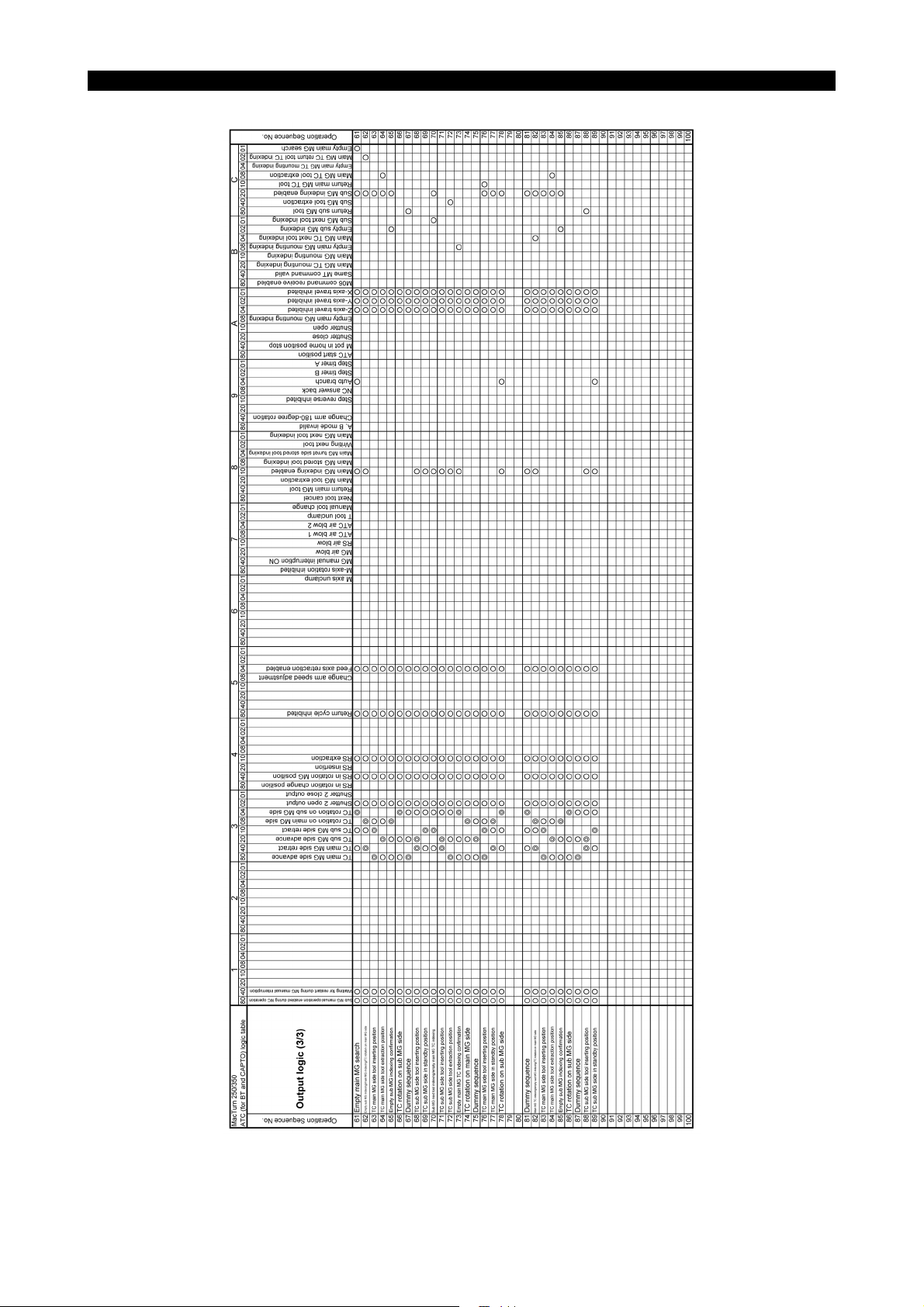
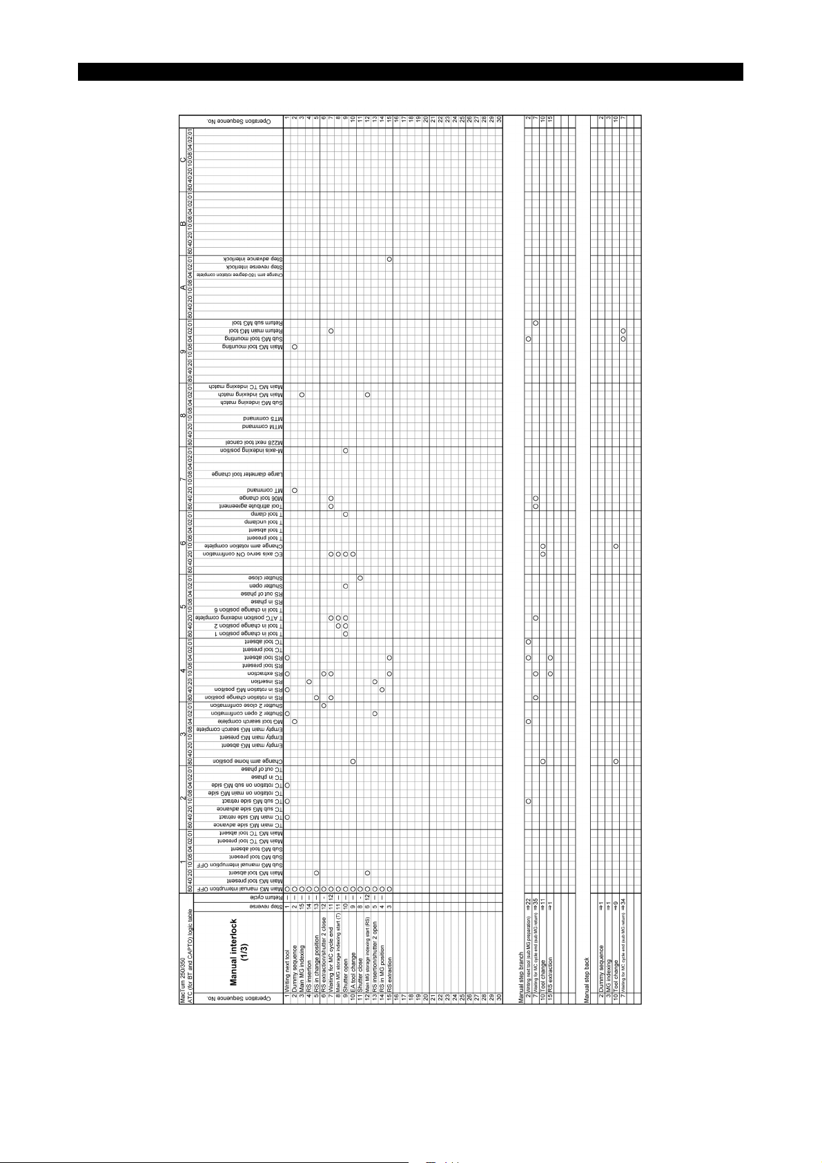
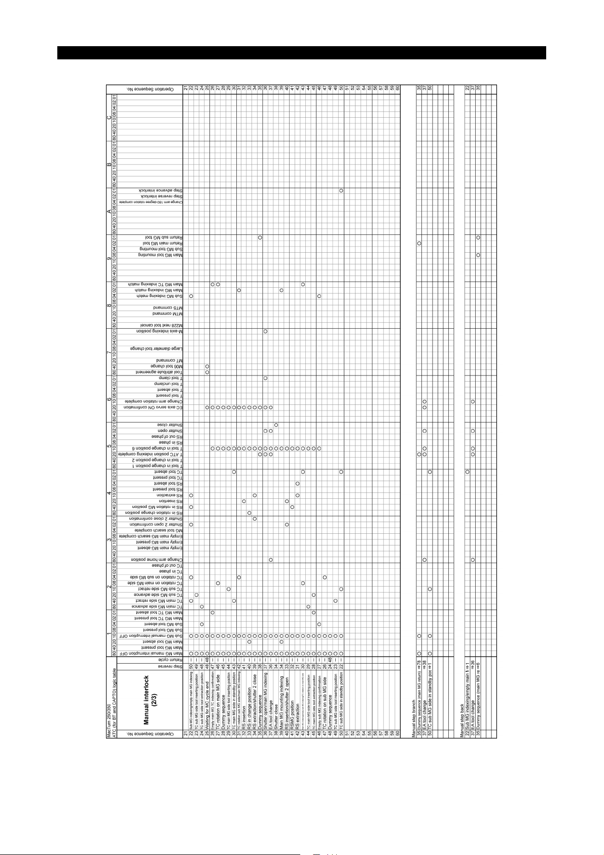
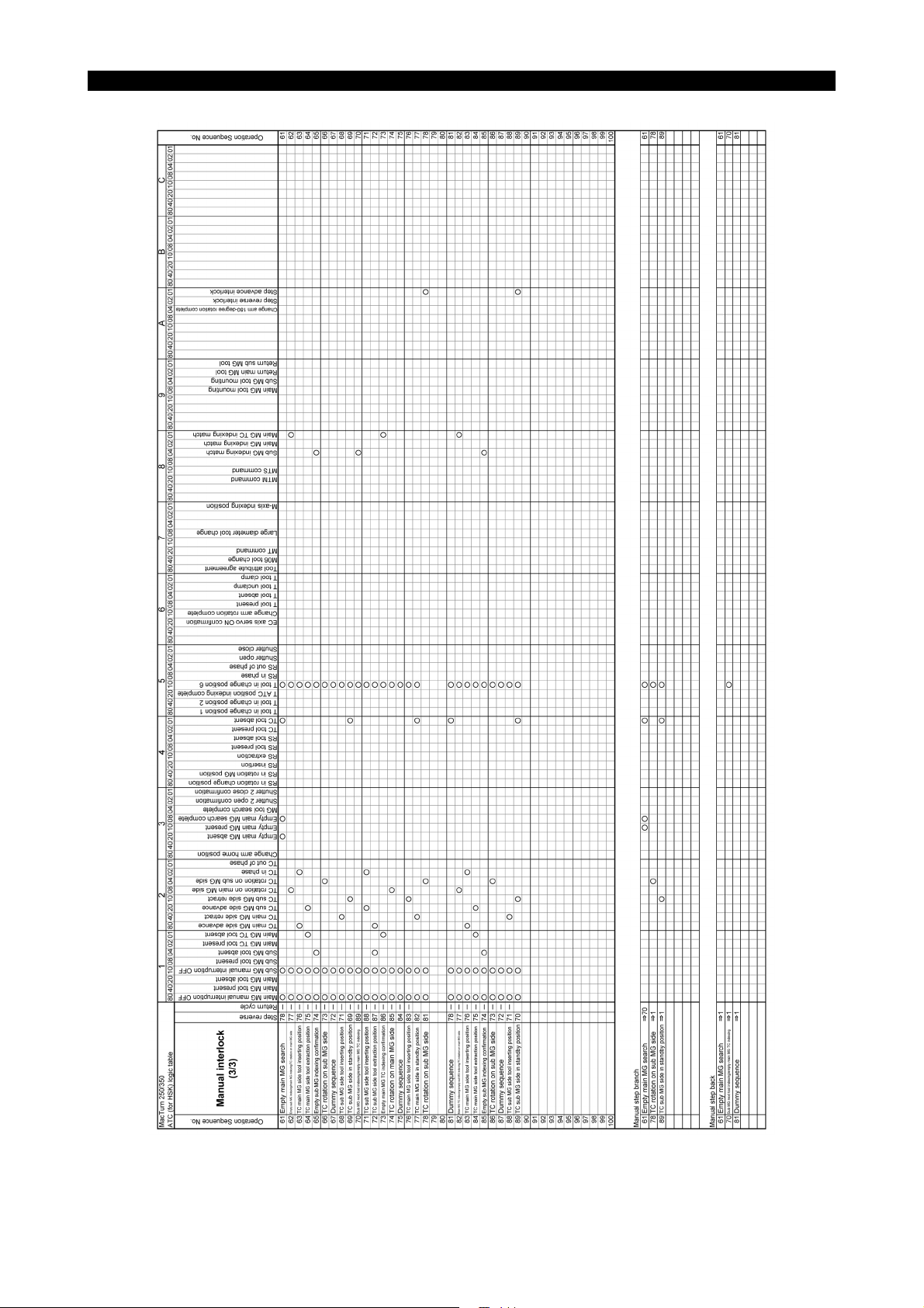
SECTION 3 ATC LOGIC TABLES
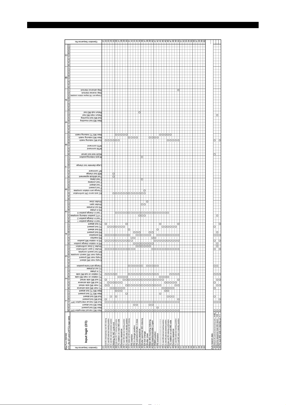
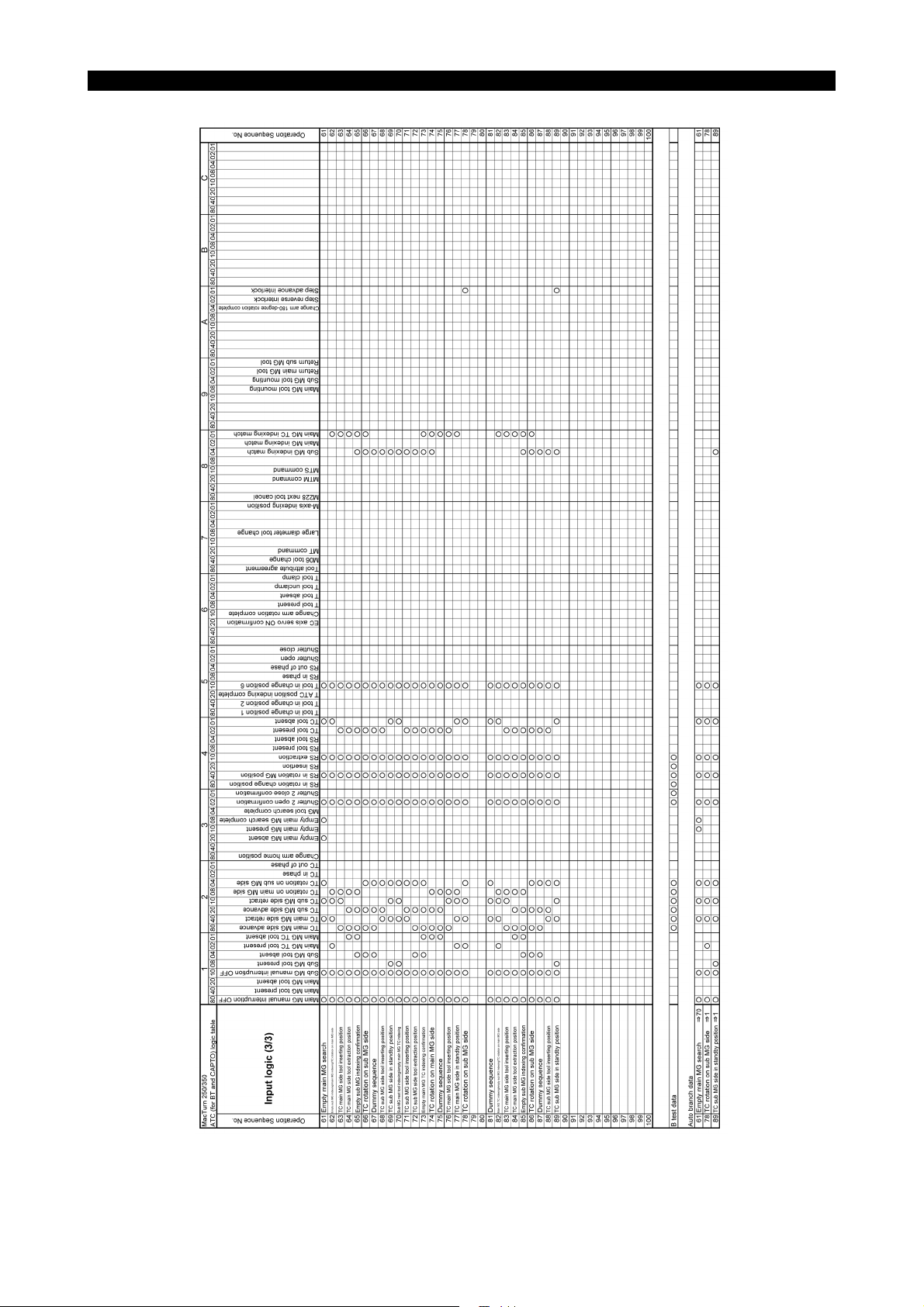
SECTION 3 ATC LOGIC TABLES
The logic tables are prepared for the respective kinds of tools. Refer to the logic table that meets the tool kind
of the tool to be used. Note that the cam axis logic table is used in common to the different kinds of tools.
For the method to read the logic tables, refer to the following manual.
OSP-P300S MACTURN/MULTUS Series Operation Manual
Page 12
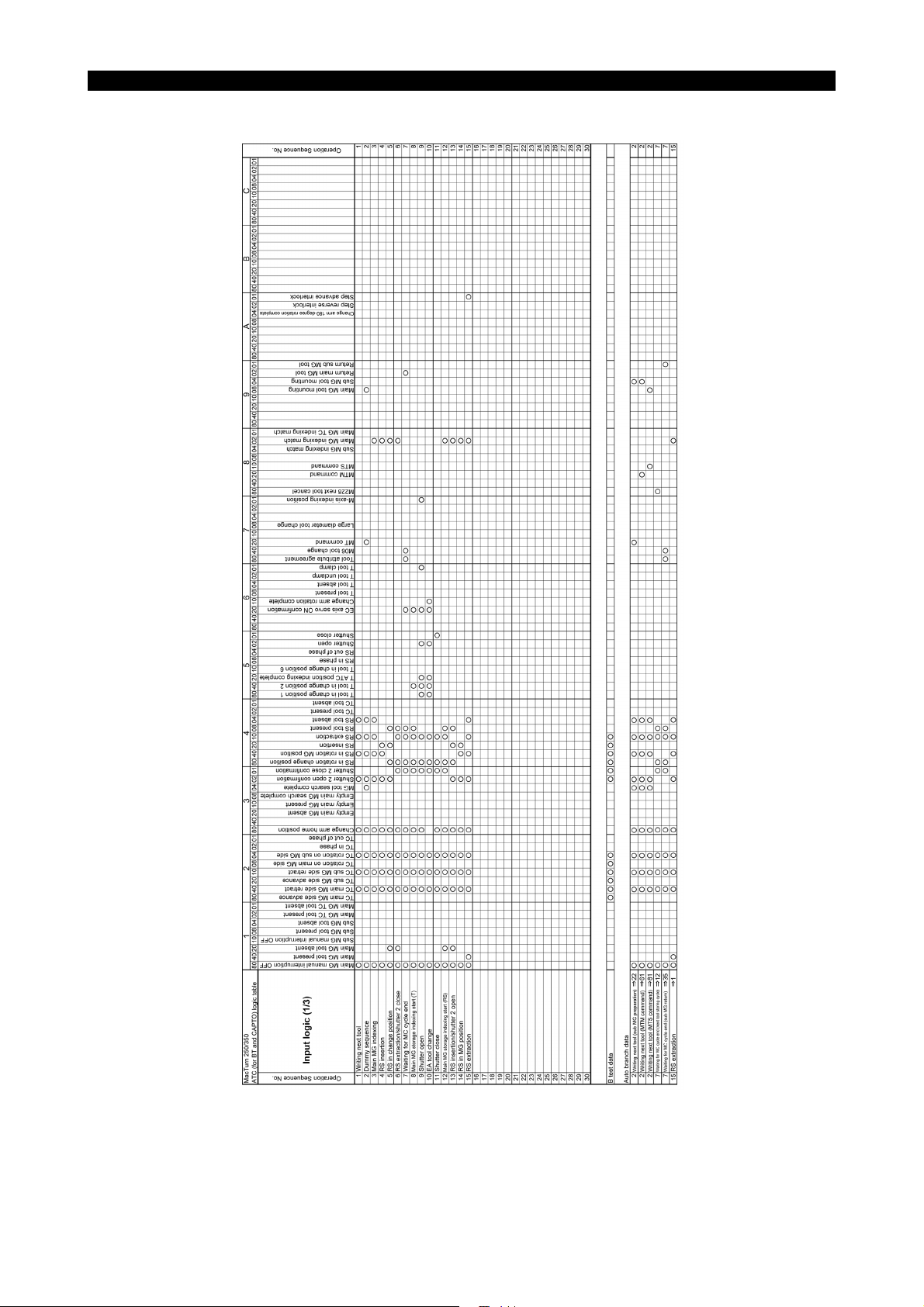
(1) BT, CAPTO Specification
6226-E P-9
SECTION 3 ATC LOGIC TABLES
LE61621R0100500010001
Page 13
6226-E P-10
SECTION 3 ATC LOGIC TABLES
LE61621R0100500010002
Page 14
6226-E P-11
SECTION 3 ATC LOGIC TABLES
LE61621R0100500010003
Page 15
6226-E P-12
SECTION 3 ATC LOGIC TABLES
LE61621R0100500010004
Page 16
6226-E P-13
SECTION 3 ATC LOGIC TABLES
LE61621R0100500010005
Page 17
6226-E P-14
SECTION 3 ATC LOGIC TABLES
LE61621R0100500010006
Page 18
6226-E P-15
SECTION 3 ATC LOGIC TABLES
LE61621R0100500010007
Page 19
6226-E P-16
SECTION 3 ATC LOGIC TABLES
LE61621R0100500010008
Page 20

6226-E P-17
SECTION 3 ATC LOGIC TABLES
LE61621R0100500010009
Page 21

(2) HSK Specification
6226-E P-18
SECTION 3 ATC LOGIC TABLES
LE61621R0100500010010
Page 22

6226-E P-19
SECTION 3 ATC LOGIC TABLES
LE61621R0100500010011
Page 23

6226-E P-20
SECTION 3 ATC LOGIC TABLES
LE61621R0100500010012
Page 24

6226-E P-21
SECTION 3 ATC LOGIC TABLES
LE61621R0100500010013
Page 25

6226-E P-22
SECTION 3 ATC LOGIC TABLES
LE61621R0100500010014
Page 26

6226-E P-23
SECTION 3 ATC LOGIC TABLES
LE61621R0100500010015
Page 27

6226-E P-24
SECTION 3 ATC LOGIC TABLES
LE61621R0100500010016
Page 28

6226-E P-25
SECTION 3 ATC LOGIC TABLES
LE61621R0100500010017
Page 29
6226-E P-26
SECTION 3 ATC LOGIC TABLES
LE61621R0100500010018
Page 30

6226-E P-27
SECTION 3 ATC LOGIC TABLES
LE61621R0100500010019
Page 31

6226-E P-28
SECTION 3 ATC LOGIC TABLES
LE61621R0100500010020
Page 32

SECTION 4 DATA SETTING
SECTION 4 DATA SETTING
This section explains how to set the tool data on the TOOL DATA SETTING screen.
1. ATC Function Display Screen
When the "machine operation" button on the machine operation panel is pressed, the optional icon
buttons are displayed on the right side of the screen.
The ATC function screen is displayed by touching the ATC icon.
(On the 1st page)
6226-E P-29
The selected magazine is displayed.
LE61621R0100600020001
The list in the pot/tool correspondence table switches between "1ST MG (main magazine)" and
"2ND MG (sub magazine)" by pressing the [F1] (MENU) key.
By operating the function keys, "1 cycle start" and "1 step advance/reverse" can be performed with
the ATC.
Page 33

(On the 2nd page)
6226-E P-30
SECTION 4 DATA SETTING
LE61621R0100600020002
This is the screen to check the conditions of each machine part.
By activating the ATC individual operation on the ATC system check mode screen of the machine
system parameter, machine operation can be executed individually.
The ATC individual operation is the function which is to be used when ATC operation becomes
disabled.
Therefore, interlocks to prevent interference become disabled during ATC individual operation.
When performing individual operations, take sufficient care for interference with each machine part
and carefully carry out the operation.
For ATC individual operations, refer to the MULTUS/MACTURN operation manual.
Page 34

2. Data Setting Screen
The TOOL DATA SETTING screen is displayed by pressing the tool data setting mode key.
By selecting the MAGAZINE INFO. sheet, the magazine conditions are displayed.
6226-E P-31
SECTION 4 DATA SETTING
LE61621R0100600030001
Page 35

2-1. Magazine Information List
The list of turret, ready station, return station, and tools mounted in the magazine is displayed on the
left side of the MAGAZINE INFO. sheet screen.
The tools mounted in the main magazine and the sub magazine are displayed in one table.
Tools are displayed as "1- (pot no,)" when mounted in the main magazine and as "2- (pot no.)" when
in the sub magazine.
When a tool is mounted by manual operation, the tool can only be mounted in the turret or in the sub
magazine; there is no operation to attach or remove a tool into or from the main magazine.
With the tool to be returned to the main magazine, "@" appears in the KIND column with turret,
ready station, and return station.
6226-E P-32
SECTION 4 DATA SETTING
The tool indicated with "@" is a
tool to be returned to the main
magazine.
LE61621R0100600040001
Page 36

2-2. List of not Mounted Tools
By pressing the function key [F2] (UNMNT-TL DISPLAY), the list of the tools which are not mounted
in any of turret, ready station, return station and magazine is displayed.
Select the tool to be mounted from the list by touching the screen.
Then press either [F1] (TURRET ATTACH) or [F2] (MAGAZINE ATTACH) to mount the tool.
(1) [F1] (TURRET ATTACH)
If the tool has been mounted in the turret already, execute tool removal.
At the time when attaching a tool in the turret, a pop-up window to specify the return magazine
appears. Select either the main magazine or the sub magazine.
6226-E P-33
SECTION 4 DATA SETTING
1ST MG -> The main magazine installed to the saddle
2ND MG -> The sub magazine installed next to the machine
LE61621R0100600050001
(2) [F2] (MAGAZINE ATTACH)
When a tool is mounted by manual operation, the tool can only be mounted in the sub
magazine; there is no operation to attach a tool into the main magazine. When attaching a tool
to the magazine, specify the pot number of the sub magazine.
Page 37

2-3. List of Lack Tools
If the tool used in the part program which is currently selected has not been mounted in any of turret,
ready station, return station and magazine, the list of the tools is displayed.
Tools in the list can be attached to the turret or to the magazine by the same operation as the not
mounted tools.
2-4. Registering and Attaching a Tool
When the function key [F1] (TOOL REG&ATT.) is pressed on the MAGAZINE INFO. sheet screen,
the TOOL REG_ATTACH sheet is displayed as shown below.
When "register" is pressed after the tool basic information and the tool model data are set, a pop-up
window to specify the return magazine appears. Select either the main magazine or the sub
magazine.
6226-E P-34
SECTION 4 DATA SETTING
1ST MG -> The main magazine installed to the saddle
2ND MG -> The sub magazine installed next to the machine
2-5. Main Magazine Tool Specification
To cancel "main magazine tool" specification, perform either of the following two methods.
(1) Specify the M code command "M652" in the MDI mode. The "main magazine tool" specifications
can be cancelled in a batch.
(2) When the tool life management function is provided, the "main magazine tool" specification is
also cancelled by canceling the specification of the selected tool with the tool index in the tool group.
LE61621R0100600070001
Page 38

SECTION 5 MANUAL OPERATION
1. Manual Magazine Operation
1-1. Overview
When mounting a tool to the magazine or replacing a tool in the magazine with another tool, it is
necessary to index the magazine to the tool change position manually. To enable this, call the
manual magazine operation mode. Usually, manual operation of the magazine is carried out for the
sub magazine (fixed magazine). To call the manual sub magazine operation mode, the machine
may not be stopped but it requires the ATC to be in the stopped state.
For details of manual operation of the magazine, refer to the following manual.
OSP-P300S MACTURN/MULTUS Series Operation Manual
[Supplement]
To select the main magazine/sub magazine, set “ON/OFF” for the corresponding machine system
parameter of “SYSTEM CHECK MODE”.
Manual main magazine operation is required in maintenance work, etc.
6226-E P-35
SECTION 5 MANUAL OPERATION
1-2. Mechanical Lock
With the MacTurn 250/350, mechanical lock device is used for the magazine door.
When the mechanical lock device is mounted, the condition below must be satisfied to turn off the
manual interruption mode.
- The magazine door must be closed to turn off the sub magazine manual interruption mode.
Pressing the [INT] key on the magazine operation panel cannot turn off the magazine manual
interruption mode in the state the “magazine manual interruption mode is ON” and the “magazine
door not closed”.
Page 39

6226-E P-36
SECTION 5 MANUAL OPERATION
2. Interlock Function for Magazine Door Open/Close Operation
The magazine door (magazine door of sub magazine) is of one door type with the mechanical lock
device mounted to it. Since the sub magazine is the fixed type magazine, ATC operation must be
stopped to open the magazine door.
The magazine door is locked when the magazine and the ATC are in any of the following states.
• During ATC operation
• During sub magazine rotation
• Sub magazine manual interruption mode OFF
Note that the magazine door is not locked in the following cases even if any of the conditions above
is satisfied.
• Machine lock state
• Magazine door close input signal OFF
• Alarm message “Please open magazine door” displayed on the screen
Page 40

3. Manual ATC Operation
This subsection explains how to perform ATC manual operation in the TOOL DATA SETTING
screen mode.
Select the MAGAZINE INFO. sheet or the TOOL DATA (ALL) sheet and press [F6] (MANUAL TOOL
CHG). Then the ATC manual operation screen appears.
6226-E P-37
SECTION 5 MANUAL OPERATION
Operable functions
LE61621R0100700040001
Procedure :
1 Select the target tool in the magazine tool list by touching the screen.
2 Select the motion to be operated and press the function keys between F1 and F4.
The functions that are operable are indicated with a green triangle mark at the left upper corner
of each function key.
[F1] (TOOL CHANGE)
This key is enabled when a tool in the magazine tool list in the MAGAZINE INFO. sheet is
selected.
This key is enabled when a tool in the tool list in the TURRET INFO. sheet is mounted in the
magazine.
[F2] (TOOL INDEX)
When the cursor is located at the current tool number in the TOOL DATA (ALL) sheet, the turret
and the M-spindle are indexed according to the posture number.
[F3] (TOOL RETURN)
This key is enabled when a tool is mounted in the turret.
Page 41

6226-E P-38
SECTION 5 MANUAL OPERATION
[F4] (NEXT TL RETURN)
This key is enabled when a tool exists in the ready station or the return station.
Interlock conditions
When all the following conditions are met, manual tool change operation can be enabled.
• In the ATC manual operation mode
• The turret is located at the X-axis positive variable limit.
• The upper turret (G13) is selected.
• Not during ATC sequence. → The ATC sequence No. is "1" and the ATC is on standby for the
MT command.
• Manual interruption OFF with the magazine operation panel
• The front door open/close confirmation limit SW has been checked at power ON.
• The front door has been closed.
• Not during manual tool attach/removal mode
Page 42

6226-E P-39
SECTION 6 ATC PROGRAM COMMANDS
SECTION 6 ATC PROGRAM COMMANDS
The commands explained below are used for controlling ATC operation for the 80/120-tool magazine
specification. The program is basically described in the sequence indicated below.
(1) Canceling the designation of “MAIN-MG TOOL”
Since the tools to be designated for “MAIN-MG TOOL” change for each main program, the command for
canceling “MAIN-MG TOOL” designation collectively for all tools is specified before starting the first
machining, in the start section of a machining program.
(2) Specifying the MTM command for all tools necessary for machining at the beginning of a machining
program
The tools designated with the MTM command (tool transfer from the sub magazine to the main
magazine) are moved from the sub magazine to the main magazine. If there is not sufficient number of
pots in the main magazine to store all tools to be used in machining, the MTM command prepares an
empty pot where the MTM designated tool is stored.
When preparing an empty pot, the tool for which “MAIN-MG TOOL” designation is canceled although it is
presently mounted in the main magazine is returned to the sub magazine.
Conversely, the tool moved from the sub magazine to the main magazine according to the execution of
the MTM command is designated as the “MAIN-MG TOOL”.
(3) Perform the tool change command by specifying an MT command, M06 command (M321/M421
commands practically), or TD command.
Page 43

1. ATC Commands
(1) MT = {{{{01: Next tool preparation command
The specified tool {{{{ is prepared for tool change operation.
With a multi-tool magazine, the specified tool is prepared on the tool transfer unit from the sub
magazine or on the ready station from the main magazine.
In either case, if the specified tool is not mounted in the magazines, alarm C "ATC Next tool
preparation disable" occurs and ATC operation is not executed.
If the MT command is executed with an ATC operation sequence number other than 1, 7 and
25, an alarm occurs.
(2) TC = 1 ...Turret indexing command to ATC position
The turret of the number (with H1 turret, fixed to "1") specified with TC is indexed to the ATC
position.
(3) M06: Tool change command
This command mounts the tool which is prepared on the tool transfer unit or on the ready
station to the turret, and returns the tool in the turret to the sub magazine or to the main
magazine.
If the M06 command is executed with an ATC operation sequence number other than 7 and 25,
an alarm occurs.
6226-E P-40
SECTION 6 ATC PROGRAM COMMANDS
(4) M321/M421: Tool change command macro
With the M321 (M421) command, the tool change position (home position) varies depending on
whether the current tool is specified as the main magazine tool or as the sub magazine tool at
the time of specification.
[When specified as a main magazine tool]
The tool moves to the tool change position HP (home position) no. 1 to execute tool change
between the main magazine and the turret.
Since the main magazine is installed on the saddle, it moves along with the ZA-axis. Thus the
tool change position is not identified with the ZA-axis.
Therefore, set the XA/YA-axis position for tool change position HP1.
[When specified as a sub magazine tool]
The tool moves to the tool change position HP (home position) no.6 to execute tool change
between the sub magazine and the turret.
The sub magazine is provided because the number of pots is not sufficient only with the main
magazine installed on the saddle, which helps not to limit the machining workpiece kinds.
Since the tool on the sub magazine is changed from the main magazine after transferred to the
main magazine by the tool transfer unit, the tool change position is identified with the ZA-axis.
Therefore, set the XA/YA/ZA-axis position for tool change position HP6.
<M421/M321 selection>
M421 and M321 can be selected by selecting the parameter.
Optional parameter Others No42 M code macro command type selection Enabled/Disabled
(Optional parameter bit No11 bit2)
Enabled → M321
Disabled → M421
Page 44

6226-E P-41
SECTION 6 ATC PROGRAM COMMANDS
(5) TD= @@{{{{ M423 (or M323) ... Tool change and indexing command (Enabled only with
the TD mode)
The tool is changed to the tool of the specified number. The turret is indexed to the specified
command.
@@: Posture number
{{{{: Tool number
The TD command and the M423 (or M323) command must be specified in the same block.
They cannot be specified in the same block as other commands.
Example of NG) G00 X1000 Z1000 TD=010001 M323
<M423/M323 selection>
M423 and M323 can be selected by selecting the parameter.
Optional parameter Others No42 M code macro command type selection Enabled/Disabled
(Optional parameter bit No11 bit2)
Enabled → M323
Disabled → M423
(6) M228 ...Tool return command
The tool prepared as the next tool is returned to the magazine.
(7) MTM = {{{{: Tool transfer command from the sub magazine to the main magazine
The command moves the specified tool {{{{ from the sub magazine to the main magazine.
When tool transfer operations from the sub magazine to the main magazine are all completed,
the command returns the block answer.
If the specified tool is not mounted in either the main or sub magazines, alarm C "ATC Next tool
preparation disable" occurs and ATC operation is not executed.
If the MTM command is executed with an ATC operation sequence number other than 1, an
alarm occurs.
(8) MTS = {{{{: Tool transfer command from the main magazine to the sub magazine
The command moves the specified tool {{{{ from the main magazine to the sub magazine.
When tool transfer operations from the main magazine to the sub magazine are all completed,
the command returns the block answer.
If the specified tool is not mounted in either the main or sub magazines, alarm C "ATC Next tool
preparation disable" occurs and ATC operation is not executed.
If the MTS command is executed with an ATC operation sequence number other than 1, an
alarm occurs.
(9) MGS = ##: Sub magazine indexing command
The command indexes magazine pot ## of the specified sub magazine to the ATC position.
When sub magazine indexing operation is completed, the command returns the block answer.
If the MGS command is executed with an ATC operation sequence number other than 1, an
alarm occurs.
(10) MG = $$: Main magazine indexing command
The command indexes magazine pot number $$ of the specified main magazine to the ATC
position.
Page 45

SECTION 6 ATC PROGRAM COMMANDS
2. Description of Machining Program
How the ATC operation commands are described in a machining program is explained below using
examples. Also refer to the following.
2-1. OSP without Tool Life Management Specification
(Example 1) When the TD command mode is used
It is necessary to register the posture number used for cutting with each tool in
advance on the TOOL DATA SETTING screen.
Moves the turret to the turret index position.
Jumps to NST1 unless work counter is "1".
Executed in the
first time of
machining
Cancels "MAIN-MG TOOL" designation collectively.
Positioning to the ATC home position.
Designates tool No. 0003 as the MAIN-MG TOOL.
6226-E P-42
Machining 1 (Tool No. 0004)
Machining 2 (Tool No.0003)
Machining 3 (Tool No.0011)
Designates tool No. 0004 as the MAIN-MG TOOL.
Designates tool No. 0011 as the MAIN-MG TOOL.
After changed to tool No. 0004, indexed to posture No.1.
Next tool preparation command (tool No. 0004)
Cutting is started.
Moves the turret to the turret indexable position.
After changed to tool No. 0003, indexed to posture No.1.
Next tool preparation command (tool No. 0011)
Cutting is started.
Moves the turret to the turret indexable position.
After changed to tool No. 0011, indexed to posture No.1.
Cutting is started.
LE61621R0100800040001
Page 46

SECTION 6 ATC PROGRAM COMMANDS
(Example 2) When no ATC macro (M321) is used with the TL command mode
Moves the turret to the turret index position.
Jumps to NST1 unless work counter is "1".
Cancels "MAIN-MG TOOL" designation collectively.
Executed in the
first time of
machining
Positioning to the ATC home position.
Designates tool No. 0003 as the MAIN-MG TOOL.
Designates tool No. 0004 as the MAIN-MG TOOL.
Designates tool No. 0011 as the MAIN-MG TOOL.
Next tool preparation command (04: tool No.)
Turret indexing and positioning to the tool change position.
Tool change command (tool No.4 is mounted in the turret)
6226-E P-43
Machining 1 (Tool No. 0004)
Machining 2 (Tool No. 0003)
Next tool preparation command (03: tool No.)
Positioning to the return position.
Indexing the turret to the cutting position.
Cutting is started.
Moves the turret to the turret indexable position.
Turret indexing and positioning to the tool change position.
Tool change command (tool No.3 is mounted in the turret)
Next tool preparation command (11: tool No.)
Positioning to the return position.
Moves the turret to the turret index position.
Indexing the turret to the cutting position.
Cutting is started.
Moves the turret to the turret indexable position.
Turret indexing and positioning to the tool change position.
Tool change command (tool No.11 is mounted in the turret)
Positioning to the return position.
Machining 3 (Tool No. 0011)
Moves the turret to the turret index position.
Cutting is started.
LE61621R0100800040002
Page 47

SECTION 6 ATC PROGRAM COMMANDS
(Example 3) When an ATC macro (M321) is used with the TL command mode
Moves the turret to the turret index position.
Jumps to NST1 unless work counter is "1".
Cancels "MAIN-MG TOOL" designation collectively.
Executed in the
first time of
machining
Positioning to the ATC home position.
Designates tool No. 0003 as the MAIN-MG TOOL.
Designates tool No. 0004 as the MAIN-MG TOOL.
Designates tool No. 0011 as the MAIN-MG TOOL.
Next tool preparation command (04: tool No.)
ATC macro command (tool No.4 is mounted in the turret)
Next tool preparation command (03: tool No.)
Moves the turret to the turret index position.
6226-E P-44
Machining 1 (Tool No. 0004)
Machining 2 (Tool No. 0003)
Machining 3 (Tool No. 0011)
Indexing the turret to the cutting position.
Cutting is started.
Moves the turret to the turret indexable position.
ATC macro command (tool No.3 is mounted in the turret)
Next tool preparation command (11: tool No.)
Moves the turret to the turret index position.
Indexing the turret to the cutting position.
Cutting is started.
Moves the turret to the turret indexable position.
ATC macro command (tool No.11 is mounted in the turret)
Moves the turret to the turret index position.
Cutting is started.
LE61621R0100800040003
Page 48

SECTION 6 ATC PROGRAM COMMANDS
2-2. OSP with Tool Life Management Specification
(Example 1) When the TD command mode is used
It is necessary to register the posture number used for cutting with each tool in advance on
the TOOL DATA SETTING screen.
Moves the turret to the turret index position.
Jumps to NA1 unless work counter is "1".
Jumps to NA2 if tool index takes place.
Executed in
the first time
of machining
Executed in the
first time of
machining and
at tool indexing
Jumps to NST1.
Cancels "MAIN-MG TOOL" designation collectively.
Positioning to the ATC home position.
Designates the selected tool in tool group No. 3 as the MAIN-MG TOOL.
Designates the selected tool in tool group No. 4 as the MAIN-MG TOOL.
Designates the selected tool in tool group No. 11 as the MAIN-MG TOOL.
6226-E P-45
After changed to the selected tool in tool group No. 4, indexed to posture No.1.
Next tool preparation command (group No.3)
Cutting is started
Machining 1 (Tool group No. 0004)
Moves the turret to the turret indexable position.
After changed to the selected tool in tool group No. 3, indexed to posture No.1.
Next tool preparation (tool No. 0011)
Cutting is started
Machining 2 (Tool group No. 0003)
Moves the turret to the turret indexable position.
After changed to the selected tool in tool group No. 11, indexed to posture No.1.
Cutting is started
Machining 3 (Tool group No. 0011)
LE61621R0100800050001
Page 49

SECTION 6 ATC PROGRAM COMMANDS
(Example 2) When no ATC macro (M321) is used with the TL command mode
Moves the turret to the turret index position.
Jumps to NA1 unless work counter is "1".
Jumps to NA2 if tool index takes place.
Executed in
the first time
of machining
Executed in the
first time of
machining and
at tool indexing
Jumps to NST1.
Cancels "MAIN-MG TOOL" designation collectively.
Positioning to the ATC home position.
Designates the selected tool in tool group No. 3 as the MAIN-MG TOOL.
Designates the selected tool in tool group No. 4 as the MAIN-MG TOOL.
Designates the selected tool in tool group No. 11 as the MAIN-MG TOOL.
Tool preparation command
Positioning to the tool change position.
Tool change command (the tool in tool group No.4 is mounted in the turret)
Next tool preparation command (group No.3)
Positioning to the return position.
Moves the turret to the turret index position.
Indexing the turret to the cutting position.
Cutting is started
6226-E P-46
Machining 1 (Tool group No. 0004)
Moves the turret to the turret indexable position.
Positioning to the tool change position.
Tool change command (the tool in tool group No.3 is mounted in the turret)
Next tool preparation command (group No.11)
Positioning to the return position.
Moves the turret to the turret index position.
Indexing the turret to the cutting position.
Cutting is started
Machining 2 (Tool group No. 0003)
Moves the turret to the turret indexable position.
Positioning to the tool change position.
Tool change command (the tool in tool group No.11 is mounted in the turret)
Positioning to the return position.
Cutting is started
Indexing the turret to the cutting position.
Machining 3 (Tool group No. 0011)
LE61621R0100800050002
Page 50

SECTION 6 ATC PROGRAM COMMANDS
(Example 3) When an ATC macro (M321) is used with the TL command mode
Moves the turret to the turret index position.
Jumps to NA1 unless work counter is "1".
Jumps to NA2 if tool index takes place.
Executed in
the first time
of machining
Executed in the
first time of
machining and
at tool indexing
Jumps to NST1
Cancels "MAIN-MG TOOL" designation collectively.
Positioning to the ATC home position.
Designates the selected tool in tool group No. 3 as the MAIN-MG TOOL.
Designates the selected tool in tool group No. 4 as the MAIN-MG TOOL.
Designates the selected tool in tool group No. 11 as the MAIN-MG TOOL.
Next tool preparation command (group No.4)
ATC macro command (the tool in tool group No.4 is mounted in the turret)
Next tool preparation command (group No.3)
Moves the turret to the turret index position.
Indexing the turret to the cutting position.
Cutting is started
Machining 1 (Tool group No. 0004)
Moves the turret to the turret indexable position.
ATC macro command (the tool in tool group No.3 is mounted in the turret)
Next tool preparation command (group No.11)
Moves the turret to the turret index position.
Indexing the turret to the cutting position.
Cutting is started
Machining 2 (Tool group No. 0003)
Moves the turret to the turret indexable position.
ATC macro command (the tool in tool group No.11 is mounted in the turret)
Indexing the turret to the cutting position.
Cutting is started
Machining 3 (Tool group No. 0011)
6226-E P-47
LE61621R0100800050003
Page 51

SECTION 6 ATC PROGRAM COMMANDS
3. ATC Commands and ATC Operation
How the ATC sequence is performed in response to the ATC command is described below. The
arrows indicate movements of a tool.
6226-E P-48
Mounted in the
main magazine
and returned to
the main
magazine
Mounted in the
sub magazine
and returned to
the sub magazine
Mounted in the
main magazine
and returned to
the sub magazine
Mounted in the
sub magazine
and returned to
the main
magazine
Sub
magazine
MT command
TD command
MT command
TD command
Transfer unit
TC
M06 command
M06 command
Main
magazine
MT command
TD command
MT command
TD command
Ready-
station
M06 command
M06 command
Turret
Moves from
sub magazine to
MTM command
main magazine
Moves from
main magazine
MTS command
to sub magazine
LE61621R0100800060001
Whether the tool is returned to the main magazine or the sub magazine is automatically determined
according to magazine specification at tool registration.
Page 52

SECTION 7 PARAMETERS
SECTION 7 PARAMETERS
1. ATC Parameter
The “ATC PARAMETER” screen called in the parameter setting mode has the pages for setting the
main magazine axis data and the sub magazine axis data, respectively.
- ZERO OFFSET : Setting unit: 0.001°, Initial value: 0.000
- BACKLASH : Setting unit: 0.001°, Initial value: 0.000
- DROOP : Setting unit: 0.001°, Initial value: 0.000
2. Machine System Parameter
2-1. System Check Mode (Machine System Parameter)
• GB (7) axis P. H. mode
Enables pulse handle feed operation for the GB axis (sub magazine axis).
6226-E P-49
• GB axis rapid feed PB
Enables axis feed operation using the feed buttons on the operation panel for the GB axis (sub
magazine axis).
• MG panel main MG control
Selects the main magazine for the control target of the magazine operation panel. Unless this
parameter is set, control target of the magazine operation panel is the sub magazine.
Page 53

2-2. ATC (Machine System Parameter)
• Sub MG tool mount MAX
Setting range: 0 - 3
Sets the number of “pots for sub magazine tools” to be secured in the main magazine.
Pots for sub magazine tools : Pots used for mounting the tools to be transferred from the sub
magazine to the main magazine before they are mounted to
the turret.
[Supplement]
When transferring a right-large diameter/heavy tool, a left-large diameter/heavy tool or a superlarge diameter/heavy tool from the main magazine to the turret or from the main magazine to the
sub magazine, or when transferring a tool from the “pot for sub magazine tool” to the turret,
designation of return pot (reserve pot designation) is not made in the main magazine for the
transferred tool.
• Main MG TC offset position
Setting range: 0 - Max. number of main magazine pots
Sets the offset data to determine the tool change position of the main magazine where tool
change is executed between the main magazine and the tool transfer unit (TC) in reference to
the tool change position where tool change is executed between the main magazine and the
ready station.
Count the number of pots, from the pot at the tool change position taken as the reference (main
magazine/ready station) to the one at the tool change position to be set (main magazine/tool
transfer unit), in the direction the pot number decreases and set it as the offset data.
6226-E P-50
SECTION 7 PARAMETERS
• Offset of Sub MG manual tool change position
Setting range: 0 - Max. number of sub magazine pots
Sets the offset data of to determine the position of the pot indexed to the magazine door in
reference to the tool change position where tool change is executed between the sub magazine
and the tool transfer unit.
Count the number of pots, from the pot at the tool change position taken as the reference to the
one indexed at the magazine door, in the direction the pot number decreases and set it as the
offset data.
• GB axis override
Setting range: 0 - 100
Sets the override value for the GB-axis (sub magazine axis) feed operation.
If “0” is set, the GB-axis operates without override.
Page 54

SECTION 8 OTHERS
1. System Variables
(1) VGINB: Tool index flag
This system variable is used for the tool life management specification. If tool index occurs in
the registered tool groups when the TLID command is executed, “1” is set for this system
variable. When tool index occurs in none of the tool groups, “0” is set.
(2) VTMMG: “MAIN-MG TOOL” designation
This system variable is used for reading if “MAIN-MG TOOL” designation is made or not for the
tool presently mounted in the turret. “1” is set if “MAIN-MG TOOL” designation is made and “0”
is set if “MAIN-MG TOOL” designation is not made. Positioning target position is judged
according to the setting of this system parameter when the ATC macro command M321/M421
is executed.
HP = 1 : Tool change between the main magazine and the turret
(“MAIN-MG TOOL” designation is made)
HP = 6 : Tool change between the sub magazine and the turret
(“MAIN-MG TOOL” designation is not made)
6226-E P-51
SECTION 8 OTHERS
2. ATC Macro Command
For the execution of ATC, the next tool preparation command (MT) and the tool change/return
command (M321, M421) are used even for the 80/120-tool magazine specification. At the execution
of the M321/M421 command, the system judges whether or not the present tool is the “MAIN-MG
TOOL” designated tool to determine the tool change operation pattern.
• If “MAIN-MG TOOL” designation is made, positioning is made to tool change HP = 1.
Tool change cycle is executed from this HP.
→ Tool change between the main magazine and the turret
• If “MAIN-MG TOOL” designation is not made, positioning is made to tool change HP = 6.
Tool change cycle is executed this HP.
→ Tool change between the sub magazine and the turret
2-1. Shutter Operation
The shutter opens simultaneously with the start of positioning to the tool change position (HP = 1) to
reduce tool change cycle time when tool change is made between the main magazine and the
turret.
When tool change is executed between the sub magazine and the turret, if the shutter opens
simultaneously with the start of positioning to the tool change position (HP = 6), the shutter remains
open for a long time since the time from the completion of positioning to the start of tool change arm
operation takes a long time. This causes coolant and chip to enter the ATC mechanism while the
shutter is open.
To avoid this, the shutter opens immediately before the start of tool change arm operation (ATC
operation sequence S8, S35) when tool change is executed between the sub magazine and the
turret.
Page 55

2-2. Flowchart
The following flowchart shows the processing sequence of the M321 (M421) command.
6226-E P-52
SECTION 8 OTHERS
LE61621R0101000040001
Page 56

6226-E P-53
SECTION 8 OTHERS
LE61621R0101000040002
Page 57

6226-E P-54
SECTION 8 OTHERS
LE61621R0101000040003
Page 58

6226-E P-55
SECTION 8 OTHERS
LE61621R0101000040004
Page 59

6226-E P-56
SECTION 9 ALARM AND ERROR
SECTION 9 ALARM AND ERROR
The alarms related to the operation of the 80/120-tool magazine specification are indicated below.
If an alarm occurred, also refer to the “Alarm & Error List” and the “OSP-P300S MACTURN/MULTUS Series
Operation Manual”.
Alarm A
8537 Magazine door Interlock
Any of the following operations is attempted while the magazine door is open.
Spindle rotation, axis movement, turret indexing, M-tool spindle rotation, sub-spindle rotation.
Or an attempt is made to open the magazine door in any of the above indicated state.
[Code]
1-> Spindle rotation
2-> M-tool spindle rotation
3-> Axis movement
4-> Turret indexing
6-> Sub-spindle or pick-off spindle rotation
7-> ATC operation
8556 No mount magazine
Alarm B
2613 Mistake in MTM command
The tool number command used with the MTM command is wrong.
The tool number specified with the MTM command is the one for the tool not mounted in the turret or
the tool mounted in a wrong turret pot.
2614 Mistake in MTS command
The tool number command used with the MTS command is wrong.
The tool number specified with the MTS command is the one for the tool not mounted in the turret or the
tool mounted in a wrong turret pot.
2615 Mistake in MGS command
The tool number command used with the MGS command is wrong.
2719 Invalid ATC command
Two or more M06 or M228 or MT or MG or MTM or MTS or MGS commands were specified at the
same time.
M06: Tool change command
M228: ATC next tool return command
MT: Next tool ready command
MG: Magazine index command
MTM: Tool transfer command from sub magazine to main magazine
MTS: Tool transfer command from main magazine to sub magazine
MGS: Sub magazine index
Page 60

SECTION 9 ALARM AND ERROR
Alarm D
4730 Magazine door open
The magazine door is open.
4741 Magazine operation panel manual interrupt
Magazine operation is manual interruption mode.
[Code]
None -> Manual interruption mode of main magazine.
1 -> Manual interruption mode of sub magazine.
(Error message)
9468 No open pot
When a tool with large diameter at the left or at the right or with super large diameter is supplied into the
magazine, a tool is mounted in the adjacent pot.
9469 Unable to clear tool No.
6226-E P-57
A tool is attempted to be removed from the main magazine by operation not from the screen (tool
setting API).
9476 Tool mount impossible
A tool is attempted to be supplied to the main magazine on the magazine supply pop-up window.
9493 Main-MG non open pot
The empty pot that is specified with "1st MG" and set with "size" on the return magazine selection popup window does not exist in the main magazine.
9494 Sub-MG non open pot
The empty pot that is specified with "2nd MG" and set with "size" on the return magazine selection popup window does not exist in the sub magazine.
Page 61

LIST OF PUBLICATIONS
Publication No. Date Edition
6226-E February 2013 1st
This manual may be at variance with the actual product due to specification or
design changes.
Please also note that specifications are subject to change without notice.
If you require clarification or further explanation of any point in this manual, please
contact your OKUMA representative.
 Loading...