

Page 1
CNC SYSTEM
OSP-E100M
OSP-E10M
ALARM & ERROR LIST
(4th Edition)
Pub No. 4293-E-R2 (ME37-005-R4) Oct. 2000
Page 2
4293-E P-(i)
SAFETY PRECAUTIONS
SAFETY PRECAUTIONS
Eeoemalpl001
The machine is equipped with safety devices which serve to protect personnel and the machine
itself from hazards arising from unforeseen accidents. However, operators must not rely exclusively
on these safety devices: they must also become fully familiar with the safety guidelines presented
below to ensure accident-free operation.This instruction manual and the warning signs attached to
the machine cover only those hazards which Okuma can predict. Be aware that they do not cover
all possible hazards.
1. Precautions Relating To Machine Installation
Eeoemalpl002
(1) Install the machine at a site where the following conditions (the conditions for achievement of
the guaranteed accuracy) apply.
•
Ambient Temperature: 17 to 25
°
C
•
Ambient humidity: 75% max. (no condensation)
•
Site not subject to direct sunlight or excessive vibration; environment as free of dust, acid,
corrosive gases, and salt spray as possible.
(2) Prepare a primary power supply that complies with the following requirements.
•
Voltage: 200V
• Voltage fluctuation: ±10% max.
•
Power supply frequency: 50/60 Hz
•
Do not draw the primary power supply from distribution panel that also supplies a major
noise source (for example an electric welder or electric discharge machine) since this could
cause malfunction of the NC unit.
•
If possible connect the machine to a ground not used by any other equipment. If there is no
choice but to use a common ground, the other equipment must not generate a large amount
of noise (such as an electric welder or electric discharge machine).
(3) Installation Environment
Observe the following points when installing the electrical control cabinet.
•
Make sure that the NC unit will not be subject to direct sunlight.
• Make sure that the electrical control cabinet will not be splashed with chips, water, or oil.
•
Make sure that the electrical control cabinet and operation panel are not subject to exces-
sive vibrations or shock.
•
The permissible ambient temperature range for the electrical control cabinet is 0 to 40
°
C.
•
The permissible ambient humidity range for the electrical control cabinet is 30 to 95% (no
condensation).
•
The maximum altitude at which the electrical control cabinet can be used is 1000 m (3281
ft.).
2. Points To Check Before Turning On The Power
Eeoemalpl003
(1) Close all the doors of the electrical control cabinet and operation panel to prevent the entry of
water, chips, and dust.
(2) Make absolutely sure that there is nobody near the moving parts of the machine, and that there
are no obstacles around the machine, before starting machine operation.
Page 3
4293-E P-(ii)
SAFETY PRECAUTIONS
(3) When turning on the power, turn on the main power disconnect switch first, then the CONTROL
ON switch on the operation panel.
3. Precautions Relating To Operation
Eeoemalpl004
(1) After turning on the power, carry out inspection and adjustment in accordance with the daily
inspection procedure described in this instruction manual.
(2) Use tools whose dimensions and type are appropriate for the work undertaken and the machine
specifications. Do not use badly worn tools since they can cause accidents.
(3) Do not for any reason touch the spindle or tool while spindle indexing is in progress since the
spindle could rotate: this is dangerous.
(4) Check that the workpiece and tool are properly secured.
(5) Never touch a workpiece or tool while it is rotating: this is extremely dangerous.
(6) Do not remove, chips by hand while machining is in progress since this is dangerous. Always
stop the machine first, then remove the chips with a brush or broom.
(7) Do not operate the machine with any of the safety devices removed. Do not operate the
machine with any of the covers removed unless it is necessary to do so.
(8) Always stop the machine before mounting or removing a tool.
(9) Do not approach or touch any moving part of the machine while it is operating.
(10) Do not touch any switch or button with wet hands. This is extremely dangerous.
(11) Before using any switch or button on the operation panel, check that it is the one intended.
4. Precautions Relating to the ATC
Eeoemalpl005
(1) The tool clamps of the magazine, spindle, etc., are designed for reliability, but it is possible that
a tool could be released and fall in the event of an unforeseen accident, exposing you to dan-
ger: do not touch or approach the ATC mechanism during ATC operation.
(2) Always inspect and change tools in the magazine in the manual magazine interrupt mode.
(3) Remove chips adhering to the magazine at appropriate intervals since they can cause misoper-
ation. Do not use compressed air to remove these chips since it will only push the chips further
in.
(4) If the ATC stops during operation for some reason and it has to be inspected without turning the
power off, do not touch the ATC since it may start moving suddenly.
5. On Finishing Work
Eeoemalpl006
(1) On finishing work, clean the vicinity of the machine.
(2) Return the ATC, APC and other equipment to the predetermined retraction position.
(3) Always turn off the power to the machine before leaving it.
(4) To turn off the power, turn off the CONTROL ON switch on the operation panel first, then the
main power disconnect switch.
Page 4
4293-E P-(iii)
SAFETY PRECAUTIONS
6. Precautions During Maintenance Inspection and When
Trouble Occurs
Eeoemalpl007
In order to prevent unforeseen accidents, damage to the machine, etc., it is essential to observe the
following points when performing maintenance inspections or during checking when trouble has
occurred.
(1) When trouble occurs, press the emergency stop button on the operation panel to stop the
machine.
(2) Consult the person responsible for maintenance to determine what corrective measures need
to be taken.
(3) If two or more persons must work together, establish signals so that they can communicate to
confirm safety before proceeding to each new step.
(4) Use only the specified replacement parts and fuses.
(5) Always turn the power off before starting inspection or changing parts.
(6) When parts are removed during inspection or repair work, always replace them as they were
and secure them properly with their screws, etc.
(7) When carrying out inspections in which measuring instruments are used - for example voltage
checks - make sure the instrument is properly calibrated.
(8) Do not keep combustible materials or metals inside the electrical control cabinet or terminal
box.
(9) Check that cables and wires are free of damage: damaged cables and wires will cause current
leakage and electric shocks.
(10) Maintenance inside the Electrical Control Cabinet
a) Switch the main power disconnect switch OFF before opening the electrical control cabinet
door.
b) Even when the main power disconnect switch is OFF, there may some residual charge in
the servo amplifier and spindle drive unit, and for this reason only service personnel are per-
mitted to perform any work on these units. Even then, they must observe the following pre-
cautions.
•
Servo amplifier
•
Discharge the residual voltage one minute after turning off the breaker inside the unit.
•
Spindle drive unit
•
Discharge the residual voltage one minute after turning off the main power disconnect
switch.
c) The electrical control cabinet contains the NC unit, and the NC unit has a printed circuit
board whose memory stores the machining programs, parameters, etc. In order to ensure
that the contents of this memory will be retained even when the power is switched off, the
memory is supplied with power by a battery. Depending on how the printed circuit boards
are handled, the contents of the memory may be destroyed and for this reason only service
personnel should handle these boards.
(11) Periodic Inspection of the Electrical Control Cabinet
a) Cleaning the cooling unit
The cooling unit in the door of the electrical control cabinet serves to prevent excessive tem-
perature rise inside the electrical control cabinet and increase the reliability of the NC unit.
Inspect the following points every three months.
•
Is the fan motor inside the cooling unit working?
The motor is normal if there is a strong draft from the unit.
Page 5
4293-E P-(iv)
SAFETY PRECAUTIONS
•
Is the external air inlet blocked?
If it is blocked, clean it with compressed air.
7. General Precautions
Eeoemalpl008
(1) Keep the vicinity of the machine clean and tidy.
(2) Wear appropriate clothing while working, and follow the instructions of someone with sufficient
training.
(3) Make sure that your clothes and hair cannot become entangled in the machine. Machine oper-
ators must wear safety equipment such as safety shoes and safety goggles.
(4) Machine operators must read the instruction manual carefully and make sure of the correct pro-
cedure before operating the machine.
(5) Memorize the position of the emergency stop button so that you can press it immediately at any
time and from any position.
(6) Do not access the inside of the control panel, transformer, motor, etc., since they contain high-
voltage terminals and other components which are extremely dangerous.
(7) If two or more persons must work together, establish signals so that they can communicate to
confirm safety before proceeding to each new step.
8. Symbols Used in This Manual
Eeoemalpl009
The following warning indications are used in this manual to draw attention to information of particu-
lar importance. Read the instructions marked with these symbols carefully and follow them.
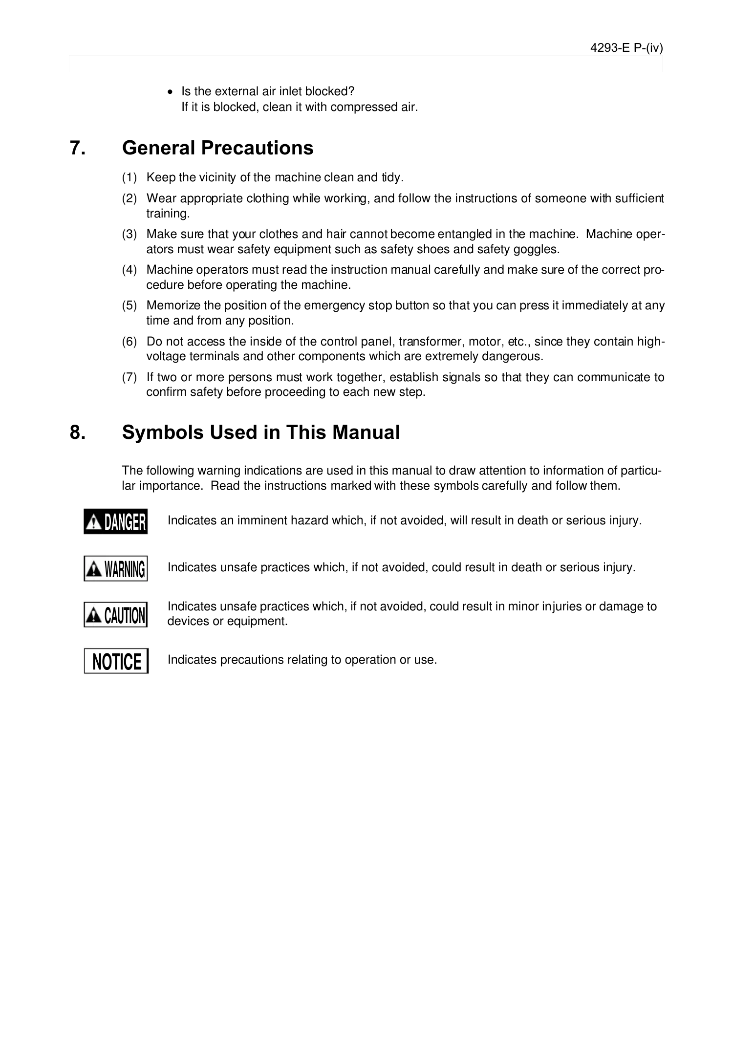
Indicates an imminent hazard which, if not avoided, will result in death or serious injury.
Indicates unsafe practices which, if not avoided, could result in death or serious injury.
Indicates unsafe practices which, if not avoided, could result in minor injuries or damage to
devices or equipment.
Indicates precautions relating to operation or use.
DANGER
WARNING
CAUTION
NOTICE
Page 6

4293-E P-(i)
INTRODUCTION
INTRODUCTION
Eeoemalan001
Before using this NC unit, read this manual thoroughly in order to ensure correct use.
This manual explains how to use and maintain the control so that it will deliver its full performance
and maintain accuracy over the long term.
You must pay particular attention to the cautions given in this manual; read them carefully and make
sure you fully understand them before operating the NC.
Page 7
4293-E P-(i)
TABLE OF CONTENTS
TABLE OF CONTENTS
CLASSIFICATION OF ALARMS ....................................................................1
CPU ALARM ...................................................................................................8
ALARM P ......................................................................................................17
ALARM A ......................................................................................................84
ALRAM B ....................................................................................................156
ALARM C ....................................................................................................302
ALARM D ....................................................................................................357
ERRORS ....................................................................................................414
APPENDIX .................................................................................................574
Page 8
4293-E P-1
SECTION 1 CLASSIFICATION OF ALARMS
SECTION 1 CLASSIFICATION OF ALARMS
Eeoemalge001
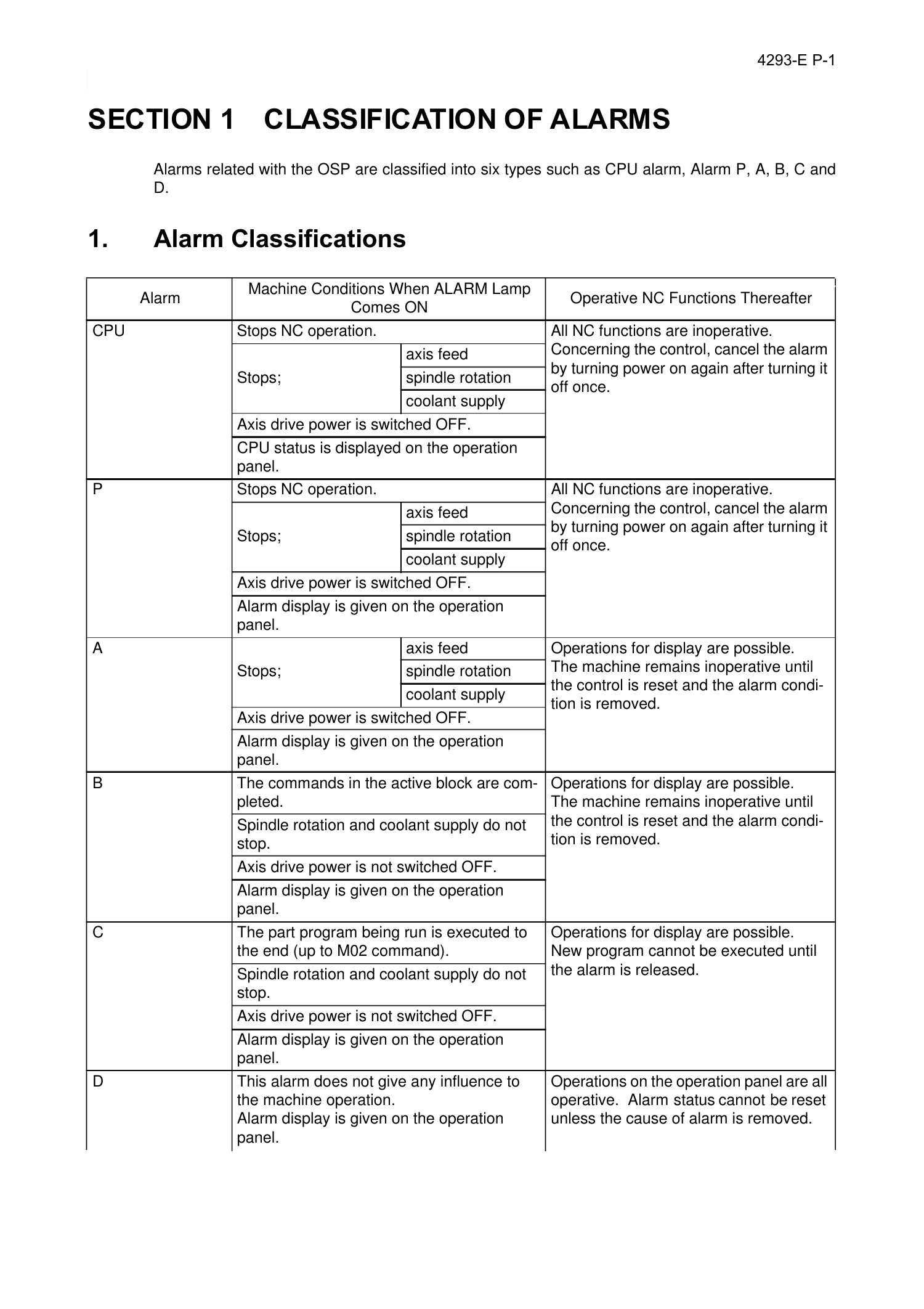
Alarms related with the OSP are classified into six types such as CPU alarm, Alarm P, A, B, C and
D.
1. Alarm Classifications
Eeoemalge002
Alarm
Machine Conditions When ALARM Lamp
Comes ON
Operative NC Functions Thereafter
CPU Stops NC operation. All NC functions are inoperative.
Concerning the control, cancel the alarm
by turning power on again after turning it
off once.
Stops;
axis feed
spindle rotation
coolant supply
Axis drive power is switched OFF.
CPU status is displayed on the operation
panel.
P Stops NC operation. All NC functions are inoperative.
Concerning the control, cancel the alarm
by turning power on again after turning it
off once.
Stops;
axis feed
spindle rotation
coolant supply
Axis drive power is switched OFF.
Alarm display is given on the operation
panel.
A
Stops;
axis feed Operations for display are possible.
The machine remains inoperative until
the control is reset and the alarm condi-
tion is removed.
spindle rotation
coolant supply
Axis drive power is switched OFF.
Alarm display is given on the operation
panel.
B The commands in the active block are com-
pleted.
Operations for display are possible.
The machine remains inoperative until
the control is reset and the alarm condi-
tion is removed.
Spindle rotation and coolant supply do not
stop.
Axis drive power is not switched OFF.
Alarm display is given on the operation
panel.
C The part program being run is executed to
the end (up to M02 command).
Operations for display are possible.
New program cannot be executed until
the alarm is released.
Spindle rotation and coolant supply do not
stop.
Axis drive power is not switched OFF.
Alarm display is given on the operation
panel.
D This alarm does not give any influence to
the machine operation.
Alarm display is given on the operation
panel.
Operations on the operation panel are all
operative. Alarm status cannot be reset
unless the cause of alarm is removed.
Page 9
4293-E P-2
SECTION 1 CLASSIFICATION OF ALARMS
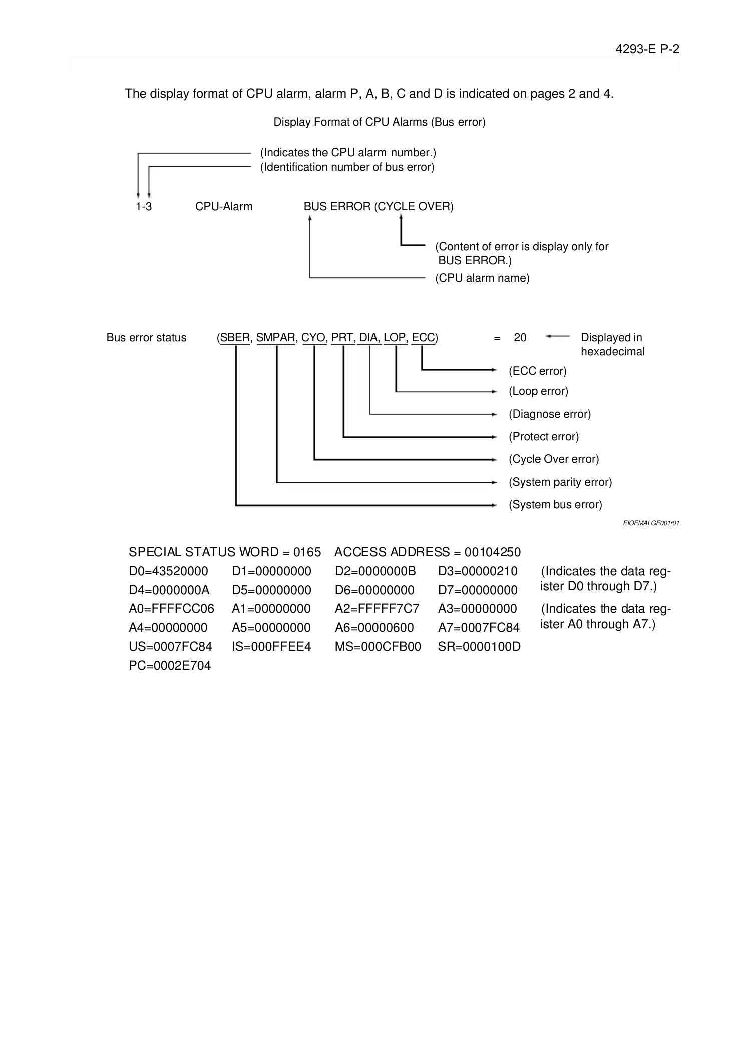
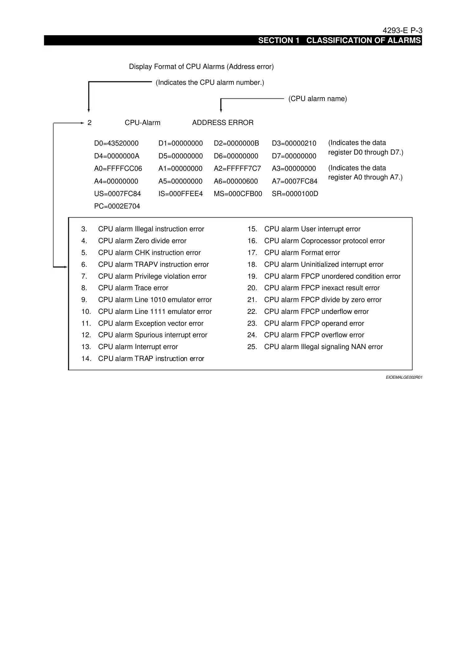
The display format of CPU alarm, alarm P, A, B, C and D is indicated on pages 2 and 4.
EIOEMALGE001r01
SPECIAL STATUS WORD = 0165 ACCESS ADDRESS = 00104250
D0=43520000 D1=00000000 D2=0000000B D3=00000210 (Indicates the data reg-
ister D0 through D7.)
D4=0000000A D5=00000000 D6=00000000 D7=00000000
A0=FFFFCC06 A1=00000000 A2=FFFFF7C7 A3=00000000 (Indicates the data reg-
ister A0 through A7.)
A4=00000000 A5=00000000 A6=00000600 A7=0007FC84
US=0007FC84 IS=000FFEE4 MS=000CFB00 SR=0000100D
PC=0002E704
Display Format of CPU Alarms (Bus error)
1-3 CPU-Alarm
Bus error status = 20
(ECC error)
Displayed in
hexadecimal
(Loop error)
(SBER, SMPAR, CYO, PRT, DIA, LOP, ECC)
BUS ERROR (CYCLE OVER)
(Content of error is display only for
BUS ERROR.)
(CPU alarm name)
(Indicates the CPU alarm number.)
(Identification number of bus error)
(Diagnose error)
(Protect error)
(Cycle Over error)
(System parity error)
(System bus error)
Page 10
4293-E P-3
SECTION 1 CLASSIFICATION OF ALARMS
EIOEMALGE002R01
Display Format of CPU Alarms (Address error)
2
3. CPU alarm Illegal instruction error 15. CPU alarm User interrupt error
4. CPU alarm Zero divide error 16. CPU alarm Coprocessor protocol error
5. CPU alarm CHK instruction error 17. CPU alarm Format error
6. CPU alarm TRAPV instruction error 18. CPU alarm Uninitialized interrupt error
7. CPU alarm Privilege violation error 19. CPU alarm FPCP unordered condition error
8. CPU alarm Trace error 20. CPU alarm FPCP inexact result error
9. CPU alarm Line 1010 emulator error 21. CPU alarm FPCP divide by zero error
10. CPU alarm Line 1111 emulator error 22. CPU alarm FPCP underflow error
11. CPU alarm Exception vector error 23. CPU alarm FPCP operand error
12. CPU alarm Spurious interrupt error 24. CPU alarm FPCP overflow error
13. CPU alarm Interrupt error 25. CPU alarm Illegal signaling NAN error
14. CPU alarm TRAP instruction error
CPU-Alarm ADDRESS ERROR
(Indicates the CPU alarm number.)
(CPU alarm name)
D0=43520000
D4=0000000A
A0=FFFFCC06
A4=00000000
US=0007FC84
PC=0002E704
D1=00000000
D5=00000000
A1=00000000
A5=00000000
IS=000FFEE4
D2=0000000B
D6=00000000
A2=FFFFF7C7
A6=00000600
MS=000CFB00
D3=00000210
D7=00000000
A3=00000000
A7=0007FC84
SR=0000100D
(Indicates the data
register D0 through D7.)
(Indicates the data
register A0 through A7.)
Page 11
4293-E P-4
SECTION 1 CLASSIFICATION OF ALARMS
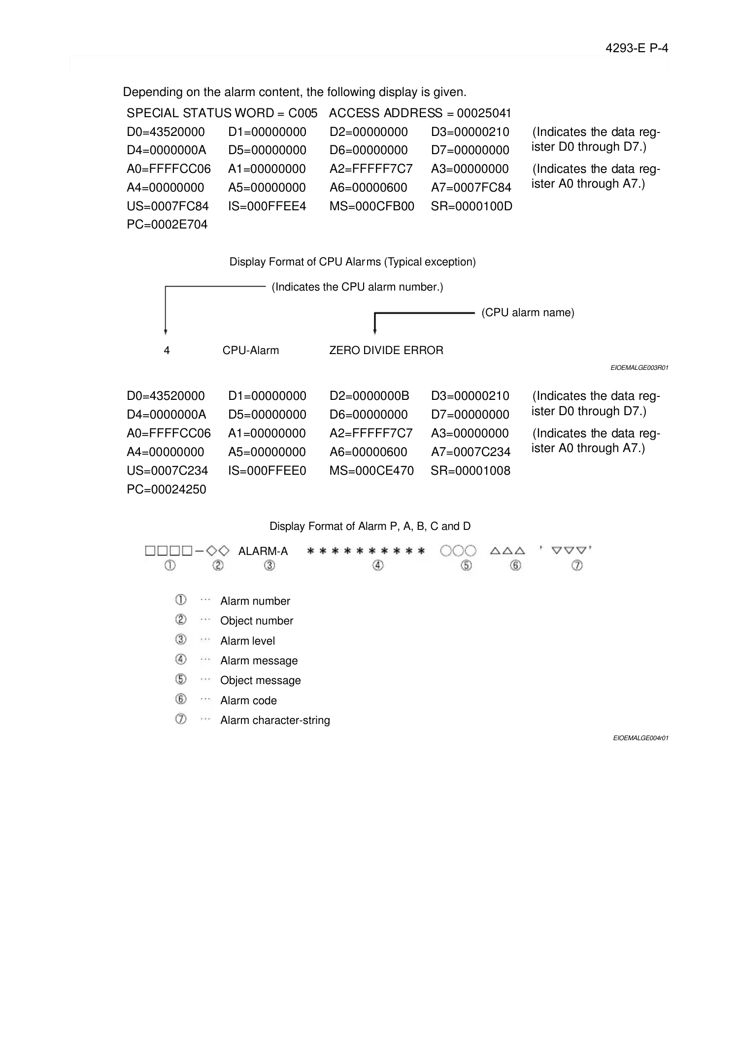
Depending on the alarm content, the following display is given.
EIOEMALGE003R01
EIOEMALGE004r01
SPECIAL STATUS WORD = C005 ACCESS ADDRESS = 00025041
D0=43520000 D1=00000000 D2=00000000 D3=00000210 (Indicates the data reg-
ister D0 through D7.)
D4=0000000A D5=00000000 D6=00000000 D7=00000000
A0=FFFFCC06 A1=00000000 A2=FFFFF7C7 A3=00000000 (Indicates the data reg-
ister A0 through A7.)
A4=00000000 A5=00000000 A6=00000600 A7=0007FC84
US=0007FC84 IS=000FFEE4 MS=000CFB00 SR=0000100D
PC=0002E704
D0=43520000 D1=00000000 D2=0000000B D3=00000210 (Indicates the data reg-
ister D0 through D7.)
D4=0000000A D5=00000000 D6=00000000 D7=00000000
A0=FFFFCC06 A1=00000000 A2=FFFFF7C7 A3=00000000 (Indicates the data reg-
ister A0 through A7.)
A4=00000000 A5=00000000 A6=00000600 A7=0007C234
US=0007C234 IS=000FFEE0 MS=000CE470 SR=00001008
PC=00024250
Display Format of CPU Alarms (Typical exception)
4 CPU-Alarm ZERO DIVIDE ERROR
(Indicates the CPU alarm number.)
(CPU alarm name)
Display Format of Alarm P, A, B, C and D
Alarm number
Object number
Alarm level
Alarm message
Object message
Alarm code
Alarm character-string
ALARM-A
Page 12
4293-E P-5
SECTION 1 CLASSIFICATION OF ALARMS
2. Object Number and Object Message
Eeoemalge003
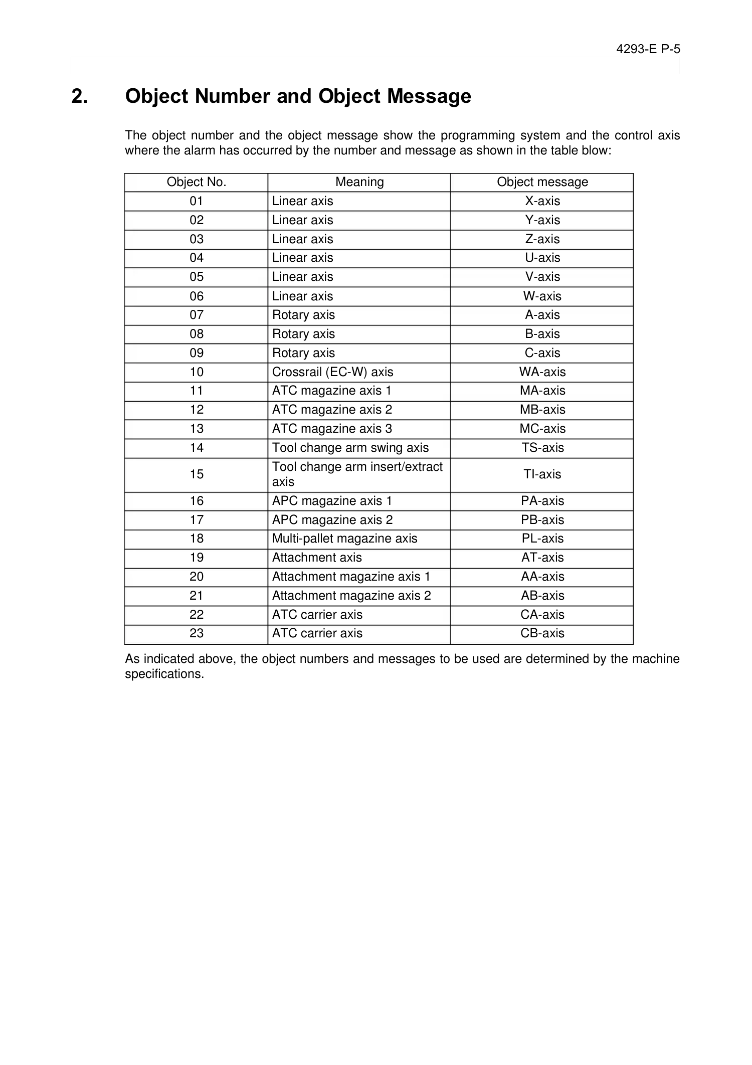
The object number and the object message show the programming system and the control axis
where the alarm has occurred by the number and message as shown in the table blow:
As indicated above, the object numbers and messages to be used are determined by the machine
specifications.
Object No. Meaning Object message
01 Linear axis X-axis
02 Linear axis Y-axis
03 Linear axis Z-axis
04 Linear axis U-axis
05 Linear axis V-axis
06 Linear axis W-axis
07 Rotary axis A-axis
08 Rotary axis B-axis
09 Rotary axis C-axis
10 Crossrail (EC-W) axis WA-axis
11 ATC magazine axis 1 MA-axis
12 ATC magazine axis 2 MB-axis
13 ATC magazine axis 3 MC-axis
14 Tool change arm swing axis TS-axis
15
Tool change arm insert/extract
axis
TI-axis
16 APC magazine axis 1 PA-axis
17 APC magazine axis 2 PB-axis
18 Multi-pallet magazine axis PL-axis
19 Attachment axis AT-axis
20 Attachment magazine axis 1 AA-axis
21 Attachment magazine axis 2 AB-axis
22 ATC carrier axis CA-axis
23 ATC carrier axis CB-axis
Page 13
4293-E P-6
SECTION 1 CLASSIFICATION OF ALARMS
2-1. Alarm Codes
Eeoemalge004
In this manual, alarm codes are explained using such as "X", "XX", and "XXYY".
Explanation is given in the following methods:
(1) The alarm code indicated in this text can be used directly as the key to find the contents of
error.
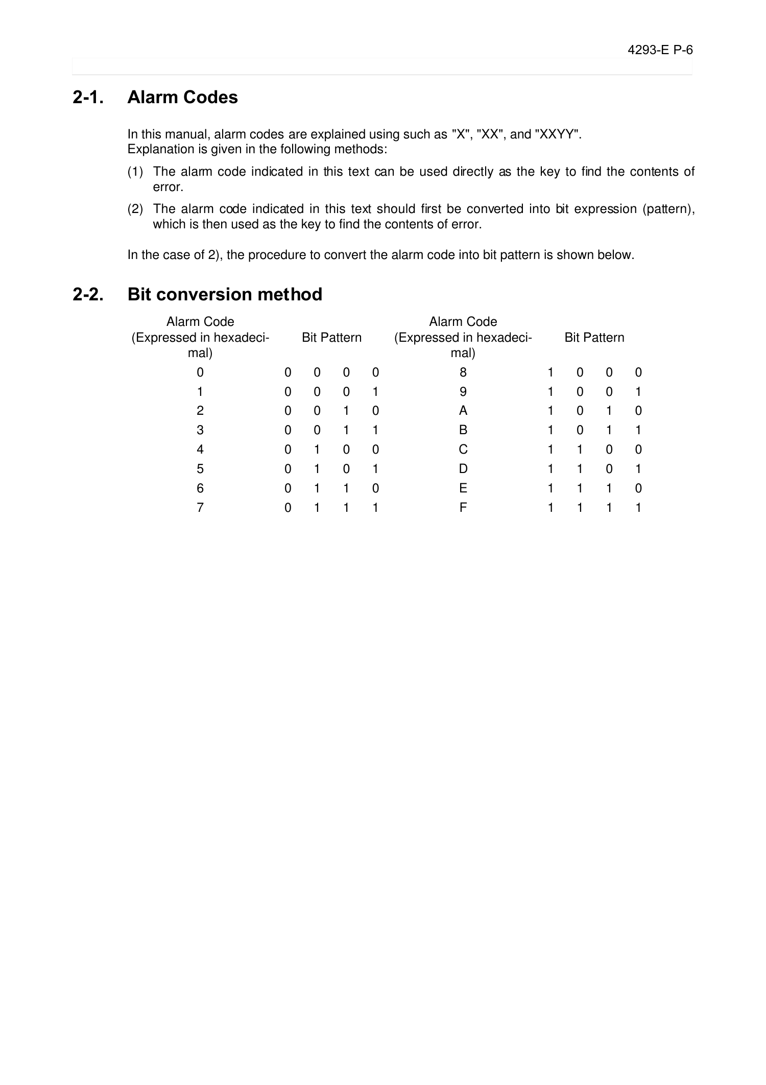
(2) The alarm code indicated in this text should first be converted into bit expression (pattern),
which is then used as the key to find the contents of error.
In the case of 2), the procedure to convert the alarm code into bit pattern is shown below.
2-2. Bit conversion method
Eeoemalge005
Alarm Code
(Expressed in hexadeci-
mal)
Bit Pattern
Alarm Code
(Expressed in hexadeci-
mal)
Bit Pattern
0 0 0 0 0 8 1 0 0 0
1 0 0 0 1 9 1 0 0 1
2 0 0 1 0 A 1 0 1 0
3 0 0 1 1 B 1 0 1 1
4 0 1 0 0 C 1 1 0 0
5 0 1 0 1 D 1 1 0 1
6 0 1 1 0 E 1 1 1 0
7 0 1 1 1 F 1 1 1 1
Page 14
4293-E P-7
SECTION 1 CLASSIFICATION OF ALARMS
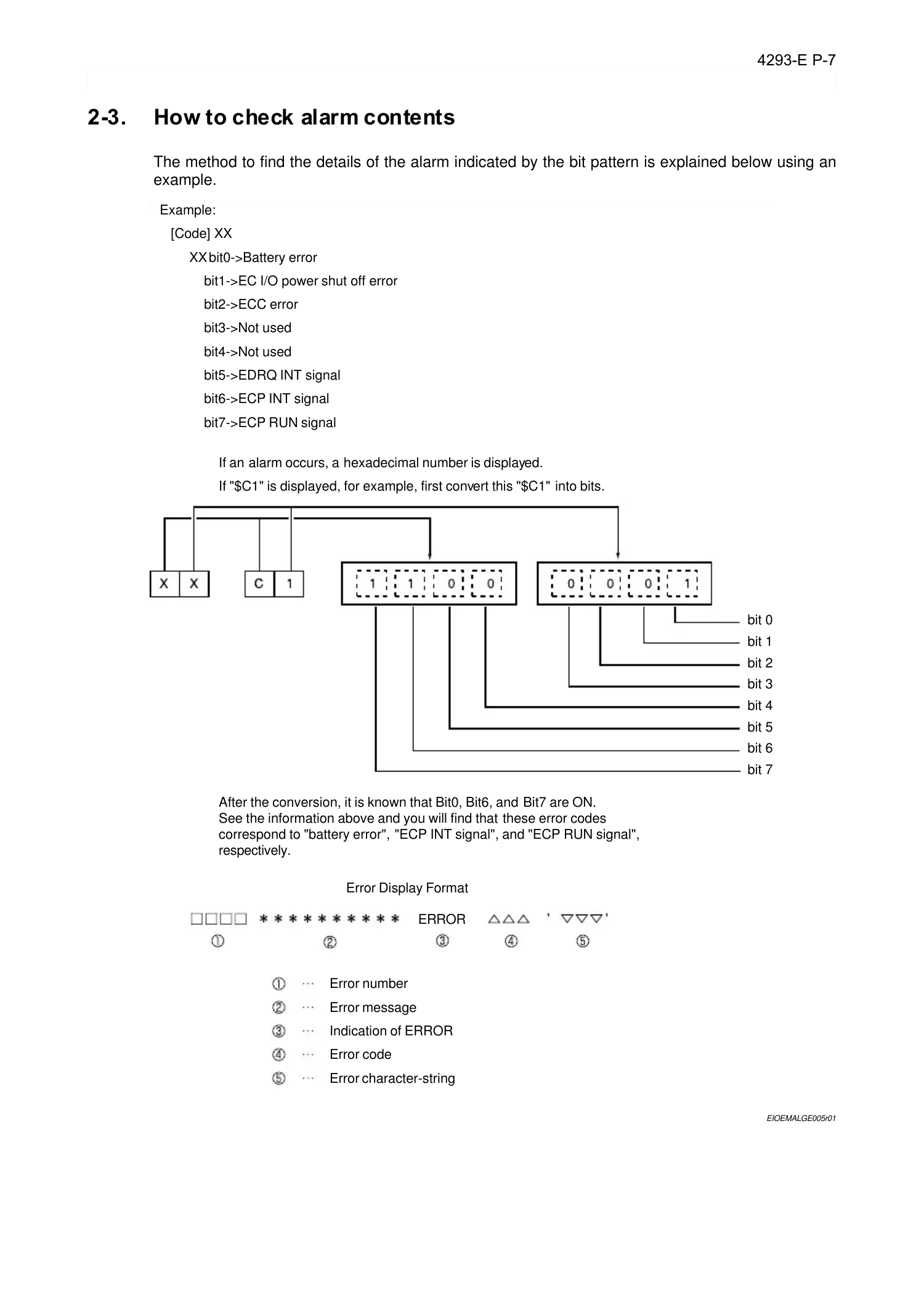
2-3. How to check alarm contents
Eeoemalge006
The method to find the details of the alarm indicated by the bit pattern is explained below using an
example.
EIOEMALGE005r01
Error Display Format
Error number
Error message
Indication of ERROR
Error code
Error character-string
After the conversion, it is known that Bit0, Bit6, and Bit7 are ON.
See the information above and you will find that these error codes
correspond to "battery error", "ECP INT signal", and "ECP RUN signal",
respectively.
Example:
[Code] XX
XX bit0->Battery error
bit1->EC I/O power shut off error
bit2->ECC error
bit3->Not used
bit4->Not used
bit5->EDRQ INT signal
bit6->ECP INT signal
bit7->ECP RUN signal
If an alarm occurs, a hexadecimal number is displayed.
If "$C1" is displayed, for example, first convert this "$C1" into bits.
bit 0
bit 1
bit 2
bit 3
bit 4
bit 5
bit 6
bit 7
ERROR
Page 15
4293-E P-8
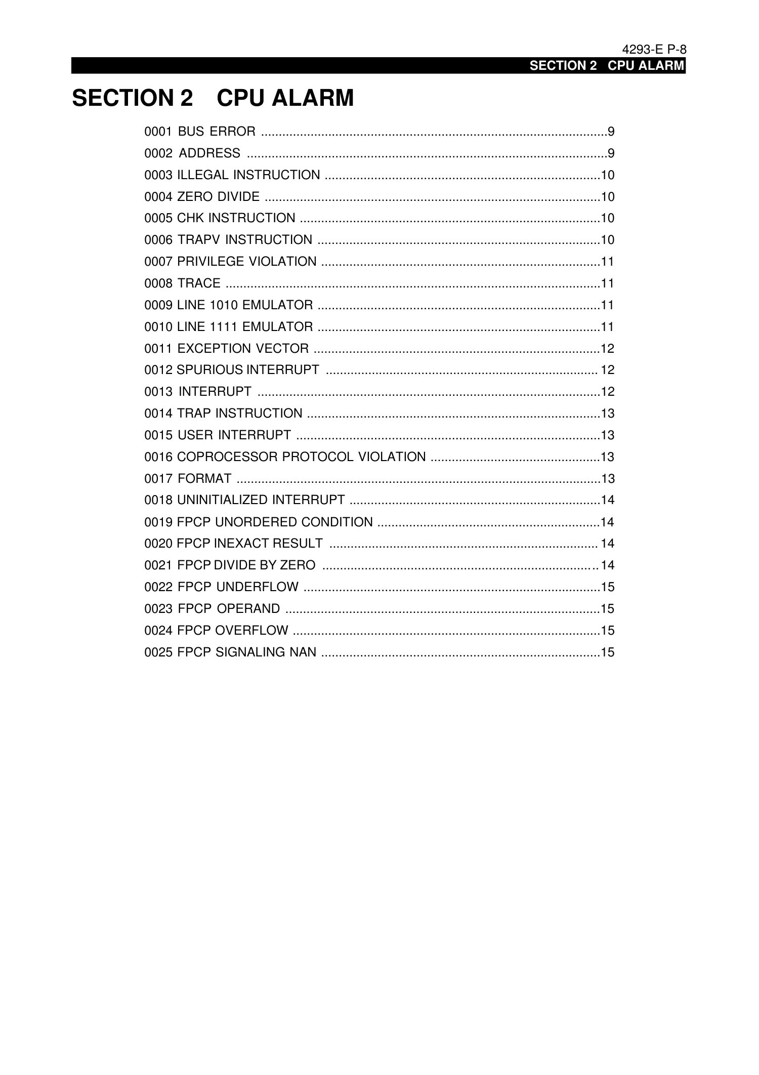
SECTION 2 CPU ALARM
SECTION 2 CPU ALARM
0001 BUS ERROR ..................................................................................................9
0002 ADDRESS ......................................................................................................9
0003 ILLEGAL INSTRUCTION ..............................................................................10
0004 ZERO DIVIDE ...............................................................................................10
0005 CHK INSTRUCTION .....................................................................................10
0006 TRAPV INSTRUCTION ................................................................................10
0007 PRIVILEGE VIOLATION ...............................................................................11
0008 TRACE ..........................................................................................................11
0009 LINE 1010 EMULATOR ................................................................................11
0010 LINE 1111 EMULATOR ................................................................................11
0011 EXCEPTION VECTOR .................................................................................12
0012 SPURIOUS INTERRUPT ............................................................................. 12
0013 INTERRUPT .................................................................................................12
0014 TRAP INSTRUCTION ...................................................................................13
0015 USER INTERRUPT ......................................................................................13
0016 COPROCESSOR PROTOCOL VIOLATION ................................................13
0017 FORMAT .......................................................................................................13
0018 UNINITIALIZED INTERRUPT .......................................................................14
0019 FPCP UNORDERED CONDITION ...............................................................14
0020 FPCP INEXACT RESULT ............................................................................ 14
0021 FPCP DIVIDE BY ZERO ..............................................................................14
0022 FPCP UNDERFLOW ....................................................................................15
0023 FPCP OPERAND .........................................................................................15
0024 FPCP OVERFLOW .......................................................................................15
0025 FPCP SIGNALING NAN ...............................................................................15
Page 16
4293-E P-9
SECTION 2 CPU ALARM
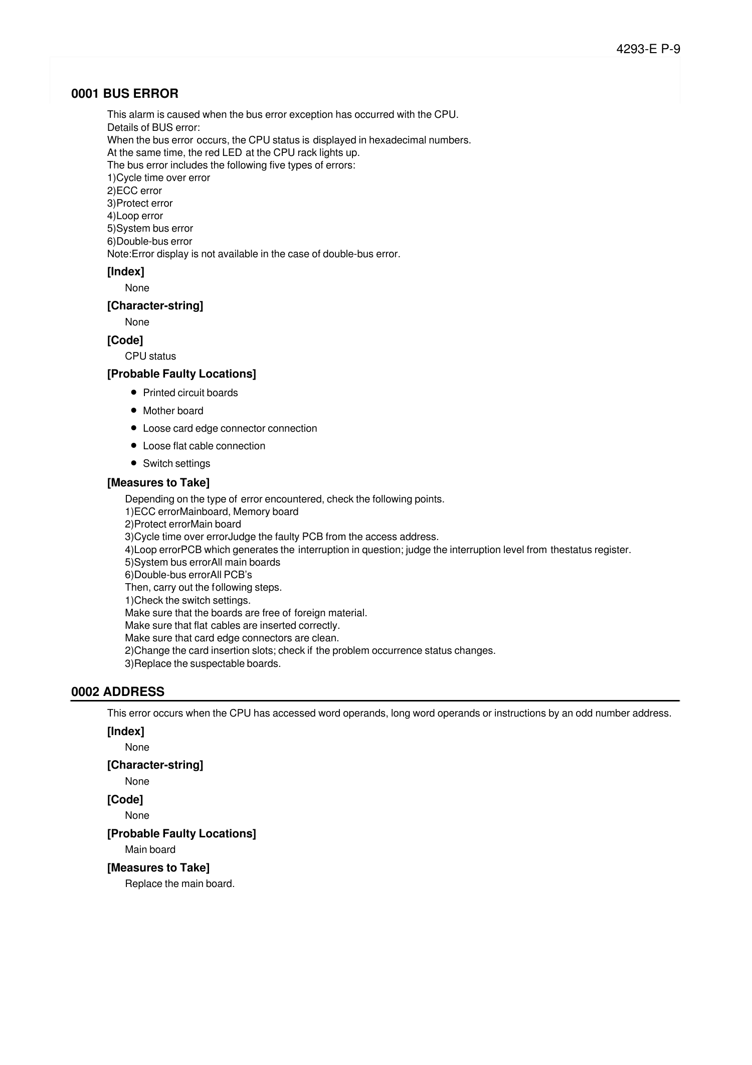
0001 BUS ERROR
Eeoemale1001
This alarm is caused when the bus error exception has occurred with the CPU.
Details of BUS error:
When the bus error occurs, the CPU status is displayed in hexadecimal numbers.
At the same time, the red LED at the CPU rack lights up.
The bus error includes the following five types of errors:
1)Cycle time over error
2)ECC error
3)Protect error
4)Loop error
5)System bus error
6)Double-bus error
Note:Error display is not available in the case of double-bus error.
[Index]
None
[Character-string]
None
[Code]
CPU status
[Probable Faulty Locations]
• Printed circuit boards
• Mother board
• Loose card edge connector connection
• Loose flat cable connection
• Switch settings
[Measures to Take]
Depending on the type of error encountered, check the following points.
1)ECC errorMainboard, Memory board
2)Protect errorMain board
3)Cycle time over errorJudge the faulty PCB from the access address.
4)Loop errorPCB which generates the interruption in question; judge the interruption level from thestatus register.
5)System bus errorAll main boards
6)Double-bus errorAll PCB’s
Then, carry out the following steps.
1)Check the switch settings.
Make sure that the boards are free of foreign material.
Make sure that flat cables are inserted correctly.
Make sure that card edge connectors are clean.
2)Change the card insertion slots; check if the problem occurrence status changes.
3)Replace the suspectable boards.
0002 ADDRESS
Eeoemale1002
This error occurs when the CPU has accessed word operands, long word operands or instructions by an odd number address.
[Index]
None
[Character-string]
None
[Code]
None
[Probable Faulty Locations]
Main board
[Measures to Take]
Replace the main board.
Page 17
4293-E P-10
SECTION 2 CPU ALARM
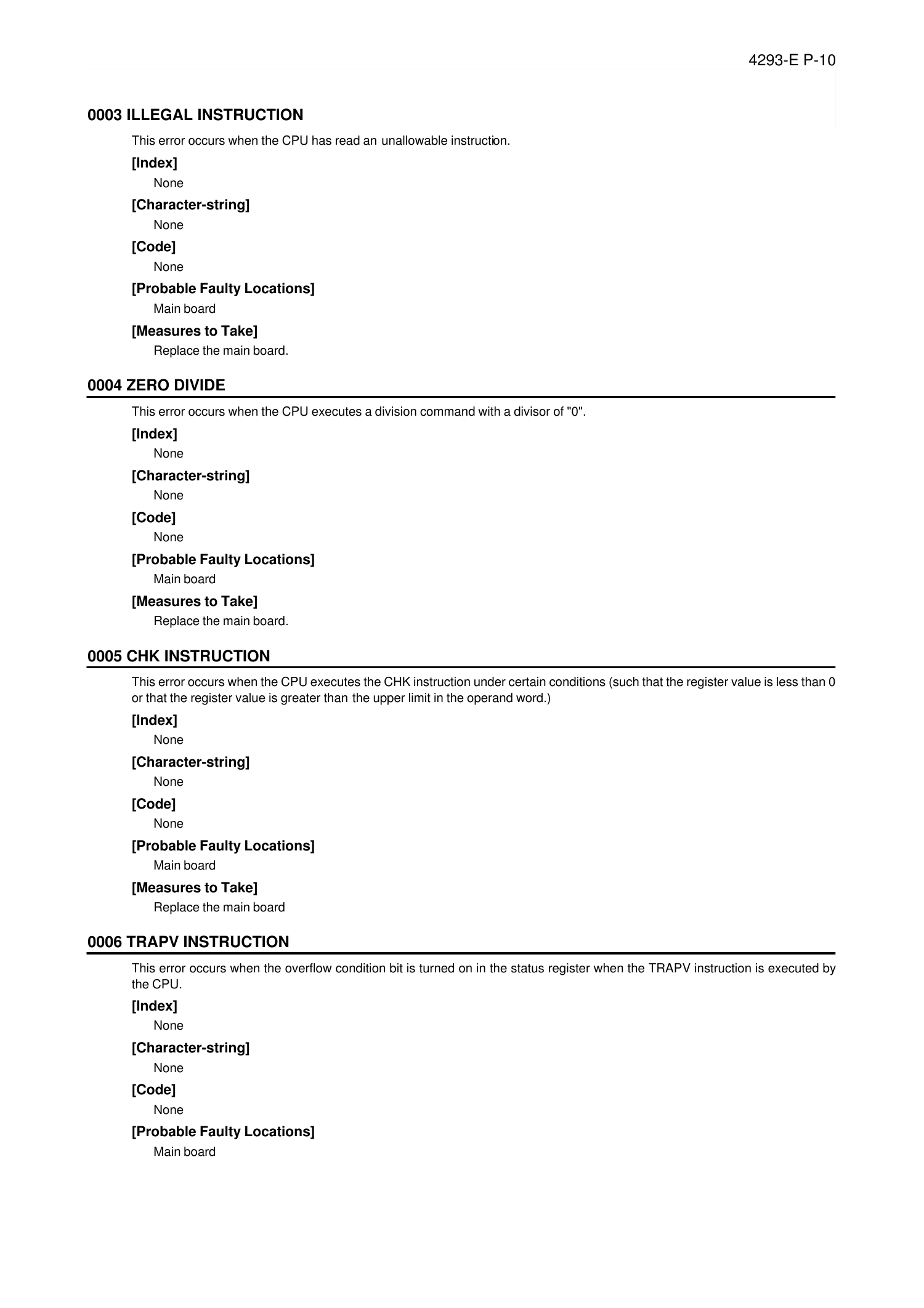
0003 ILLEGAL INSTRUCTION
Eeoemale1003
This error occurs when the CPU has read an unallowable instruction.
[Index]
None
[Character-string]
None
[Code]
None
[Probable Faulty Locations]
Main board
[Measures to Take]
Replace the main board.
0004 ZERO DIVIDE
Eeoemale1004
This error occurs when the CPU executes a division command with a divisor of "0".
[Index]
None
[Character-string]
None
[Code]
None
[Probable Faulty Locations]
Main board
[Measures to Take]
Replace the main board.
0005 CHK INSTRUCTION
Eeoemale1005
This error occurs when the CPU executes the CHK instruction under certain conditions (such that the register value is less than 0
or that the register value is greater than the upper limit in the operand word.)
[Index]
None
[Character-string]
None
[Code]
None
[Probable Faulty Locations]
Main board
[Measures to Take]
Replace the main board
0006 TRAPV INSTRUCTION
Eeoemale1006
This error occurs when the overflow condition bit is turned on in the status register when the TRAPV instruction is executed by
the CPU.
[Index]
None
[Character-string]
None
[Code]
None
[Probable Faulty Locations]
Main board
Page 18
4293-E P-11
SECTION 2 CPU ALARM
[Measures to Take]
Replace the main board.
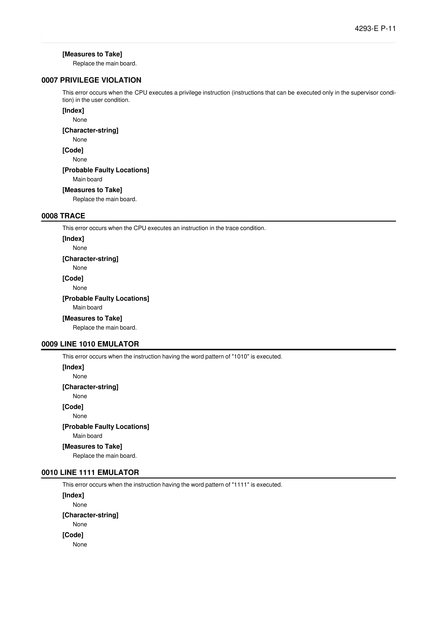
0007 PRIVILEGE VIOLATION
Eeoemale1007
This error occurs when the CPU executes a privilege instruction (instructions that can be executed only in the supervisor condi-
tion) in the user condition.
[Index]
None
[Character-string]
None
[Code]
None
[Probable Faulty Locations]
Main board
[Measures to Take]
Replace the main board.
0008 TRACE
Eeoemale1008
This error occurs when the CPU executes an instruction in the trace condition.
[Index]
None
[Character-string]
None
[Code]
None
[Probable Faulty Locations]
Main board
[Measures to Take]
Replace the main board.
0009 LINE 1010 EMULATOR
Eeoemale1009
This error occurs when the instruction having the word pattern of "1010" is executed.
[Index]
None
[Character-string]
None
[Code]
None
[Probable Faulty Locations]
Main board
[Measures to Take]
Replace the main board.
0010 LINE 1111 EMULATOR
Eeoemale1010
This error occurs when the instruction having the word pattern of "1111" is executed.
[Index]
None
[Character-string]
None
[Code]
None
Page 19
4293-E P-12
SECTION 2 CPU ALARM
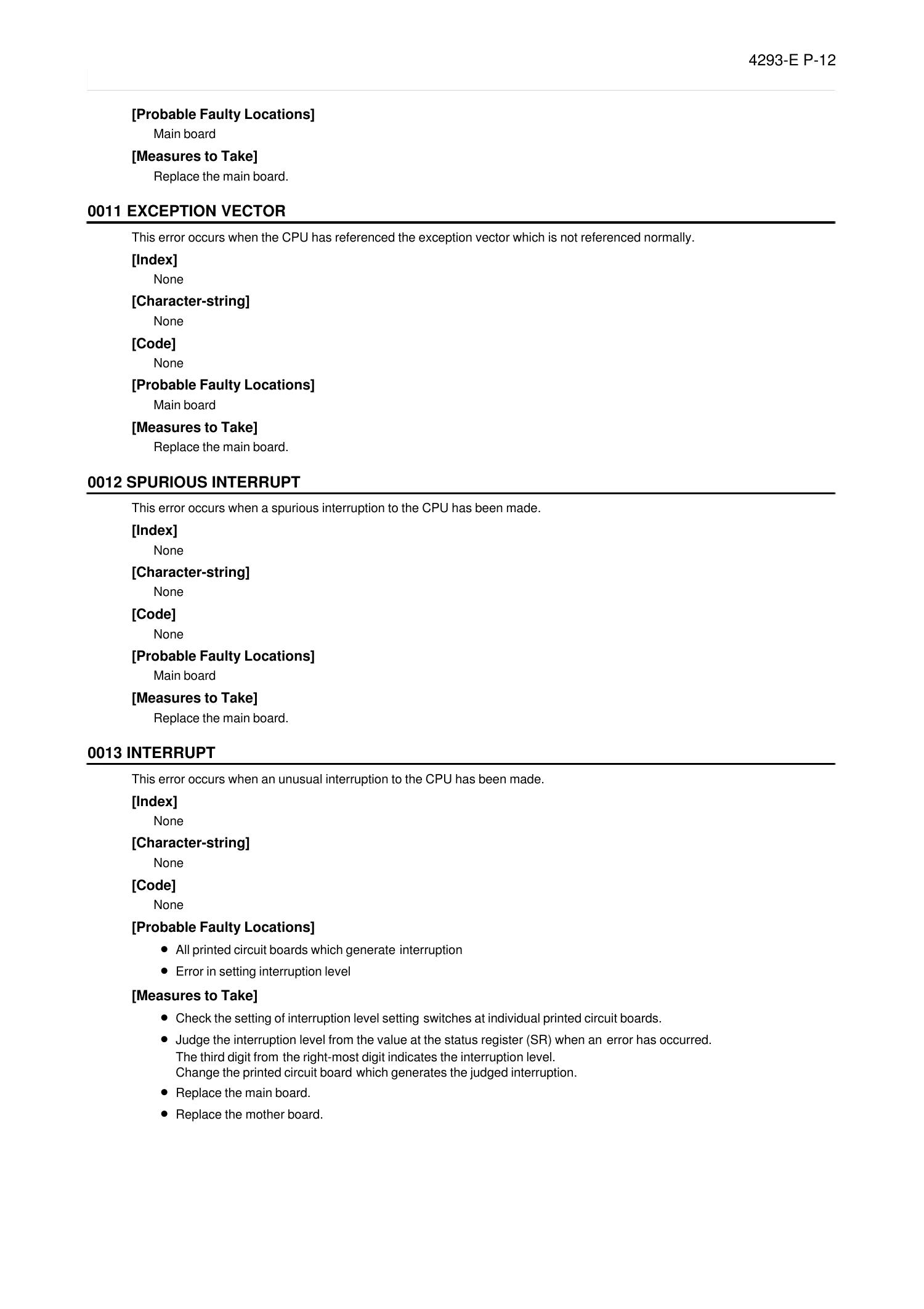
[Probable Faulty Locations]
Main board
[Measures to Take]
Replace the main board.
0011 EXCEPTION VECTOR
Eeoemale1011
This error occurs when the CPU has referenced the exception vector which is not referenced normally.
[Index]
None
[Character-string]
None
[Code]
None
[Probable Faulty Locations]
Main board
[Measures to Take]
Replace the main board.
0012 SPURIOUS INTERRUPT
Eeoemale1012
This error occurs when a spurious interruption to the CPU has been made.
[Index]
None
[Character-string]
None
[Code]
None
[Probable Faulty Locations]
Main board
[Measures to Take]
Replace the main board.
0013 INTERRUPT
Eeoemale1013
This error occurs when an unusual interruption to the CPU has been made.
[Index]
None
[Character-string]
None
[Code]
None
[Probable Faulty Locations]
• All printed circuit boards which generate interruption
• Error in setting interruption level
[Measures to Take]
•
Check the setting of interruption level setting switches at individual printed circuit boards.
• Judge the interruption level from the value at the status register (SR) when an error has occurred.
The third digit from the right-most digit indicates the interruption level.
Change the printed circuit board which generates the judged interruption.
• Replace the main board.
• Replace the mother board.
Page 20
4293-E P-13
SECTION 2 CPU ALARM
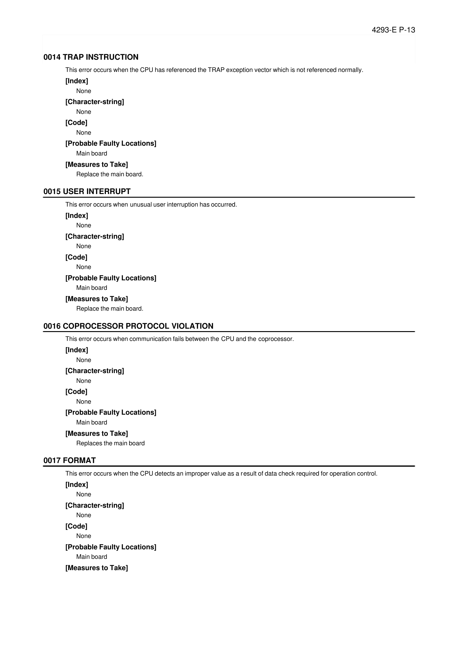
0014 TRAP INSTRUCTION
Eeoemale1014
This error occurs when the CPU has referenced the TRAP exception vector which is not referenced normally.
[Index]
None
[Character-string]
None
[Code]
None
[Probable Faulty Locations]
Main board
[Measures to Take]
Replace the main board.
0015 USER INTERRUPT
Eeoemale1015
This error occurs when unusual user interruption has occurred.
[Index]
None
[Character-string]
None
[Code]
None
[Probable Faulty Locations]
Main board
[Measures to Take]
Replace the main board.
0016 COPROCESSOR PROTOCOL VIOLATION
Eeoemale1016
This error occurs when communication fails between the CPU and the coprocessor.
[Index]
None
[Character-string]
None
[Code]
None
[Probable Faulty Locations]
Main board
[Measures to Take]
Replaces the main board
0017 FORMAT
Eeoemale1017
This error occurs when the CPU detects an improper value as a result of data check required for operation control.
[Index]
None
[Character-string]
None
[Code]
None
[Probable Faulty Locations]
Main board
[Measures to Take]
Page 21
4293-E P-14
SECTION 2 CPU ALARM
Replaces the main board
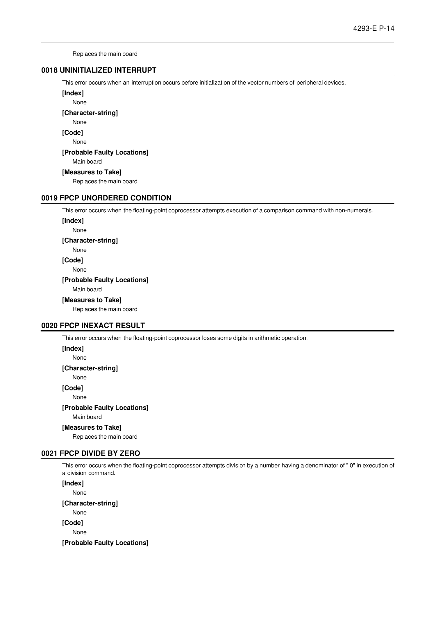
0018 UNINITIALIZED INTERRUPT
Eeoemale1018
This error occurs when an interruption occurs before initialization of the vector numbers of peripheral devices.
[Index]
None
[Character-string]
None
[Code]
None
[Probable Faulty Locations]
Main board
[Measures to Take]
Replaces the main board
0019 FPCP UNORDERED CONDITION
Eeoemale1019
This error occurs when the floating-point coprocessor attempts execution of a comparison command with non-numerals.
[Index]
None
[Character-string]
None
[Code]
None
[Probable Faulty Locations]
Main board
[Measures to Take]
Replaces the main board
0020 FPCP INEXACT RESULT
Eeoemale1020
This error occurs when the floating-point coprocessor loses some digits in arithmetic operation.
[Index]
None
[Character-string]
None
[Code]
None
[Probable Faulty Locations]
Main board
[Measures to Take]
Replaces the main board
0021 FPCP DIVIDE BY ZERO
Eeoemale1021
This error occurs when the floating-point coprocessor attempts division by a number having a denominator of " 0" in execution of
a division command.
[Index]
None
[Character-string]
None
[Code]
None
[Probable Faulty Locations]
Page 22
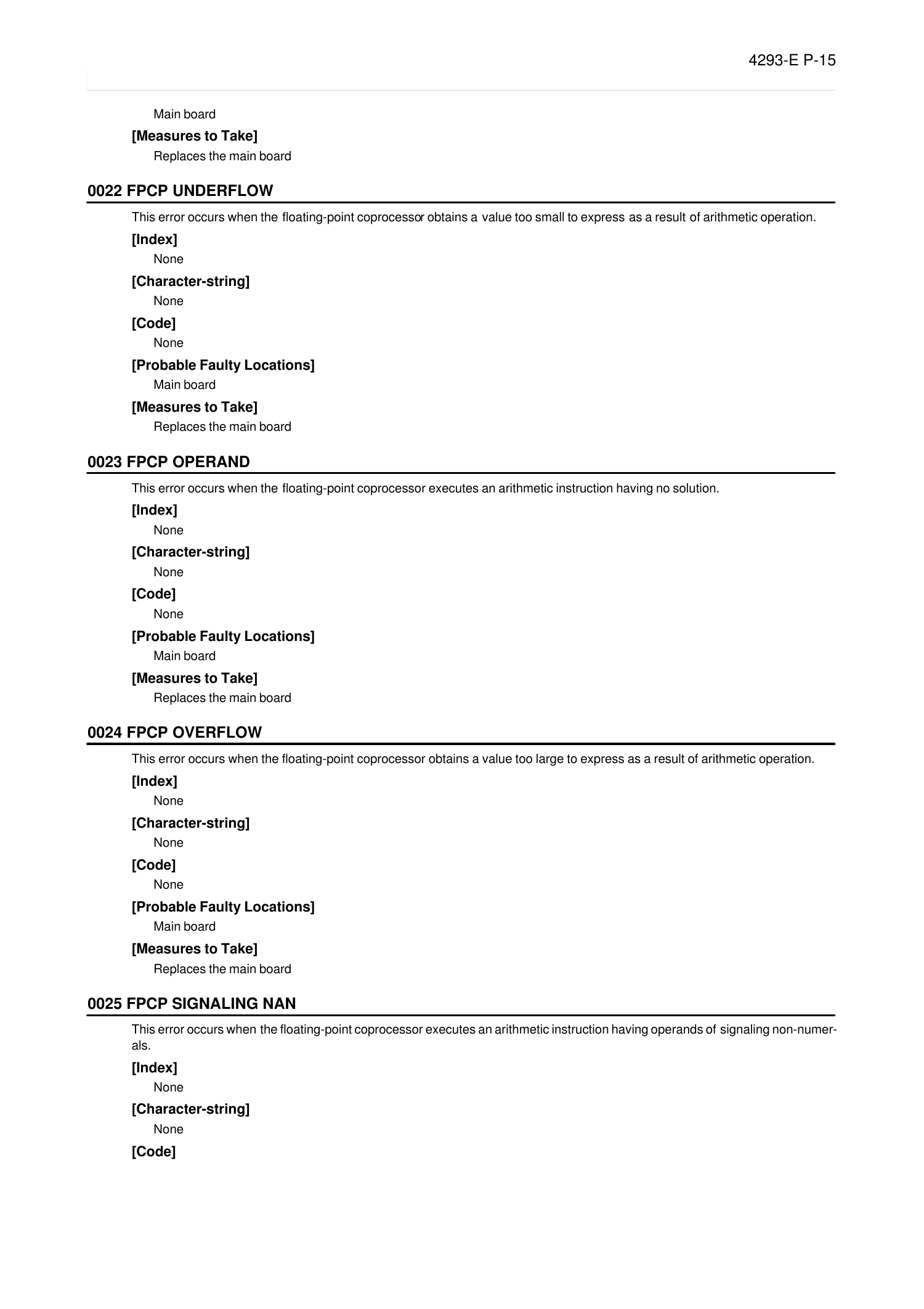
4293-E P-15
SECTION 2 CPU ALARM
Main board
[Measures to Take]
Replaces the main board
0022 FPCP UNDERFLOW
Eeoemale1022
This error occurs when the floating-point coprocessor obtains a value too small to express as a result of arithmetic operation.
[Index]
None
[Character-string]
None
[Code]
None
[Probable Faulty Locations]
Main board
[Measures to Take]
Replaces the main board
0023 FPCP OPERAND
Eeoemale1023
This error occurs when the floating-point coprocessor executes an arithmetic instruction having no solution.
[Index]
None
[Character-string]
None
[Code]
None
[Probable Faulty Locations]
Main board
[Measures to Take]
Replaces the main board
0024 FPCP OVERFLOW
Eeoemale1024
This error occurs when the floating-point coprocessor obtains a value too large to express as a result of arithmetic operation.
[Index]
None
[Character-string]
None
[Code]
None
[Probable Faulty Locations]
Main board
[Measures to Take]
Replaces the main board
0025 FPCP SIGNALING NAN
Eeoemale1025
This error occurs when the floating-point coprocessor executes an arithmetic instruction having operands of signaling non-numer-
als.
[Index]
None
[Character-string]
None
[Code]
Page 23

4293-E P-16
SECTION 2 CPU ALARM
None
[Probable Faulty Locations]
Main board
[Measures to Take]
Replaces the main board
Page 24
4293-E P-17
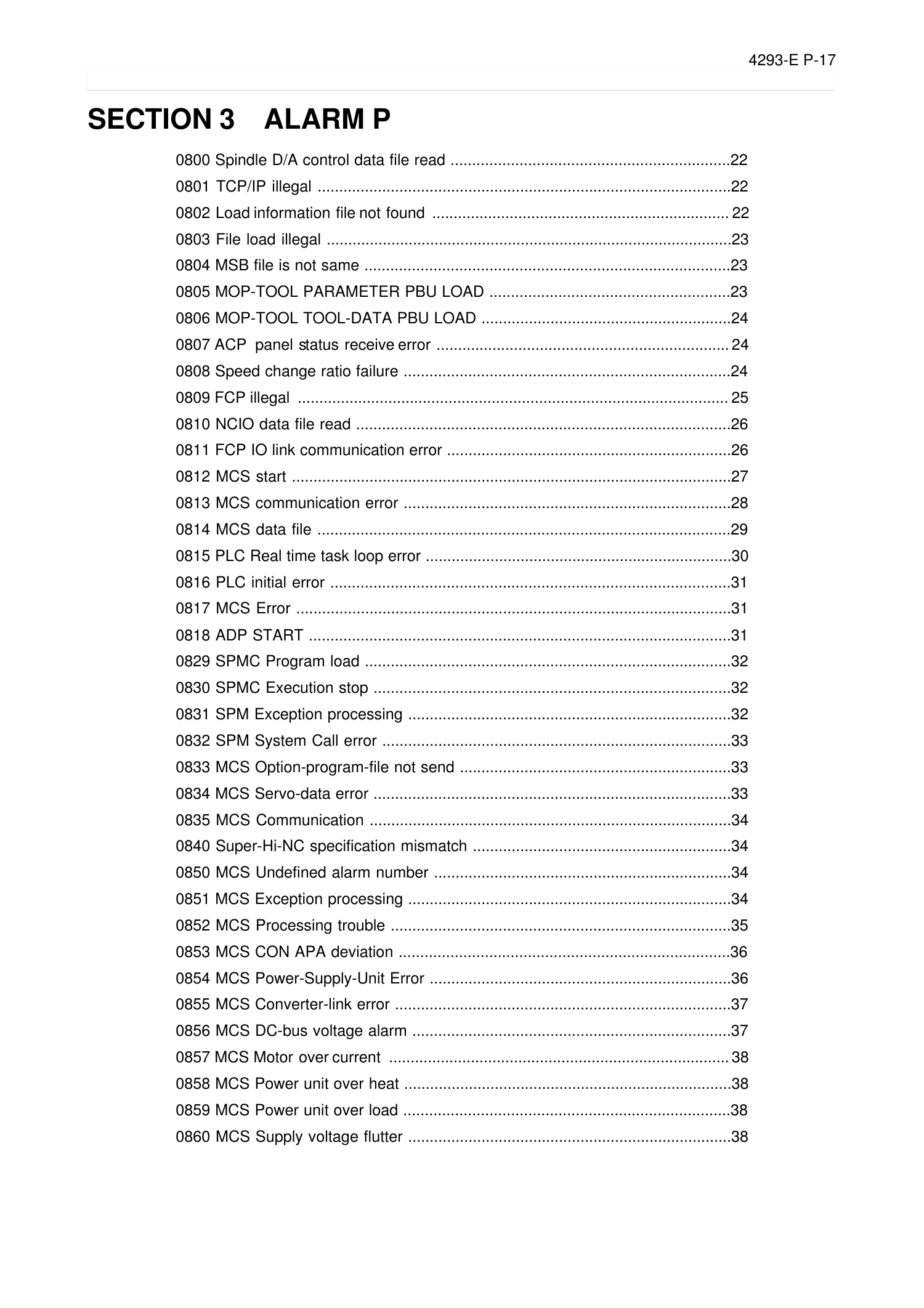
SECTION 3 ALARM P
SECTION 3 ALARM P
0800 Spindle D/A control data file read .................................................................22
0801 TCP/IP illegal ................................................................................................22
0802 Load information file not found ..................................................................... 22
0803 File load illegal ..............................................................................................23
0804 MSB file is not same .....................................................................................23
0805 MOP-TOOL PARAMETER PBU LOAD ........................................................23
0806 MOP-TOOL TOOL-DATA PBU LOAD ..........................................................24
0807 ACP panel status receive error .................................................................... 24
0808 Speed change ratio failure ............................................................................24
0809 FCP illegal .................................................................................................... 25
0810 NCIO data file read .......................................................................................26
0811 FCP IO link communication error ..................................................................26
0812 MCS start ......................................................................................................27
0813 MCS communication error ............................................................................28
0814 MCS data file ................................................................................................29
0815 PLC Real time task loop error .......................................................................30
0816 PLC initial error .............................................................................................31
0817 MCS Error .....................................................................................................31
0818 ADP START ..................................................................................................31
0829 SPMC Program load .....................................................................................32
0830 SPMC Execution stop ...................................................................................32
0831 SPM Exception processing ...........................................................................32
0832 SPM System Call error .................................................................................33
0833 MCS Option-program-file not send ...............................................................33
0834 MCS Servo-data error ...................................................................................33
0835 MCS Communication ....................................................................................34
0840 Super-Hi-NC specification mismatch ............................................................34
0850 MCS Undefined alarm number .....................................................................34
0851 MCS Exception processing ...........................................................................34
0852 MCS Processing trouble ...............................................................................35
0853 MCS CON APA deviation .............................................................................36
0854 MCS Power-Supply-Unit Error ......................................................................36
0855 MCS Converter-link error ..............................................................................37
0856 MCS DC-bus voltage alarm ..........................................................................37
0857 MCS Motor over current ............................................................................... 38
0858 MCS Power unit over heat ............................................................................38
0859 MCS Power unit over load ............................................................................38
0860 MCS Supply voltage flutter ...........................................................................38
Page 25
4293-E P-18
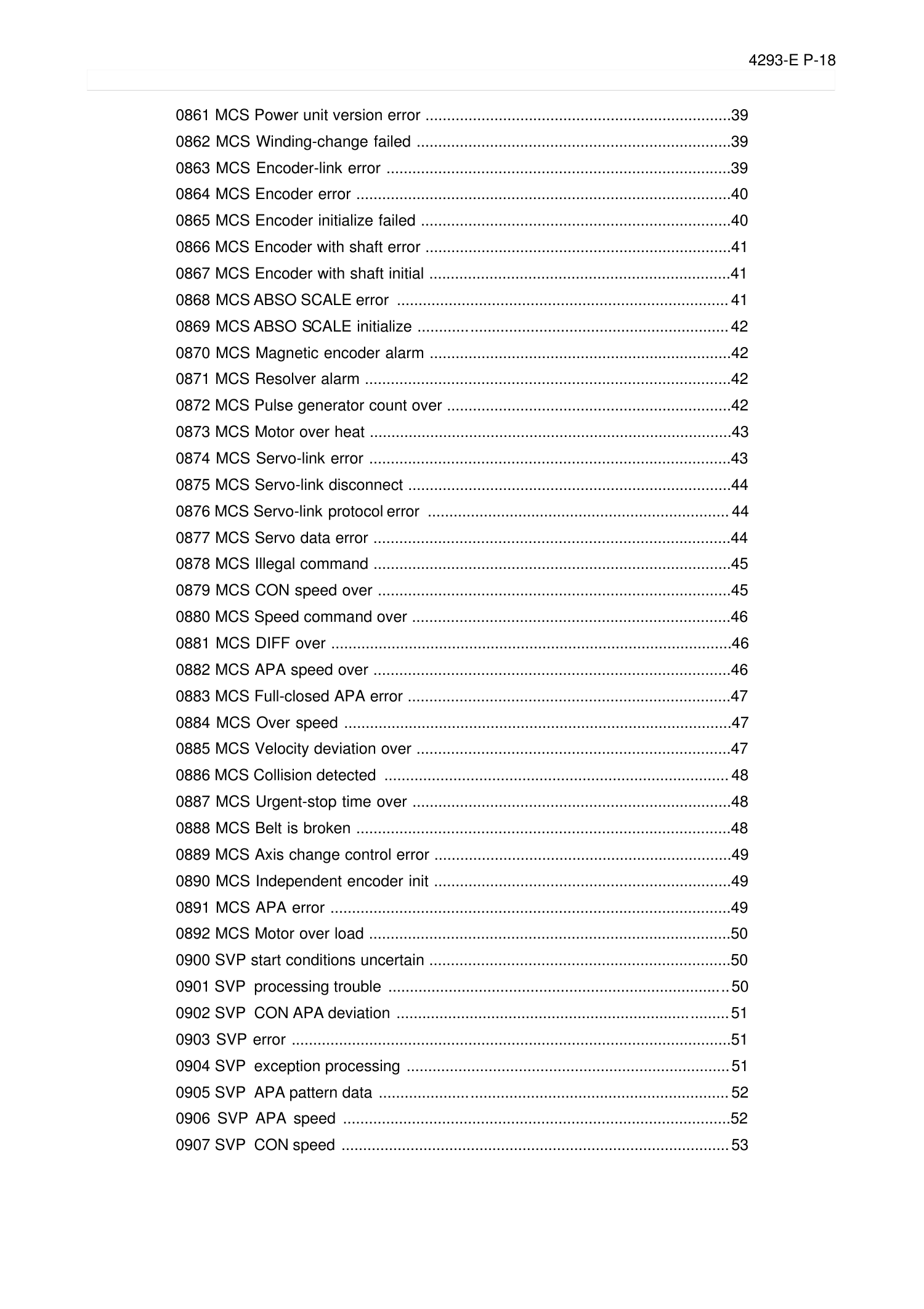
SECTION 3 ALARM P
0861 MCS Power unit version error .......................................................................39
0862 MCS Winding-change failed .........................................................................39
0863 MCS Encoder-link error ................................................................................39
0864 MCS Encoder error .......................................................................................40
0865 MCS Encoder initialize failed ........................................................................40
0866 MCS Encoder with shaft error .......................................................................41
0867 MCS Encoder with shaft initial ......................................................................41
0868 MCS ABSO SCALE error .............................................................................41
0869 MCS ABSO SCALE initialize ........................................................................ 42
0870 MCS Magnetic encoder alarm ......................................................................42
0871 MCS Resolver alarm .....................................................................................42
0872 MCS Pulse generator count over ..................................................................42
0873 MCS Motor over heat ....................................................................................43
0874 MCS Servo-link error ....................................................................................43
0875 MCS Servo-link disconnect ...........................................................................44
0876 MCS Servo-link protocol error ...................................................................... 44
0877 MCS Servo data error ...................................................................................44
0878 MCS Illegal command ...................................................................................45
0879 MCS CON speed over ..................................................................................45
0880 MCS Speed command over ..........................................................................46
0881 MCS DIFF over .............................................................................................46
0882 MCS APA speed over ...................................................................................46
0883 MCS Full-closed APA error ...........................................................................47
0884 MCS Over speed ..........................................................................................47
0885 MCS Velocity deviation over .........................................................................47
0886 MCS Collision detected ................................................................................48
0887 MCS Urgent-stop time over ..........................................................................48
0888 MCS Belt is broken .......................................................................................48
0889 MCS Axis change control error .....................................................................49
0890 MCS Independent encoder init .....................................................................49
0891 MCS APA error .............................................................................................49
0892 MCS Motor over load ....................................................................................50
0900 SVP start conditions uncertain ......................................................................50
0901 SVP processing trouble ............................................................................... 50
0902 SVP CON APA deviation ............................................................................. 51
0903 SVP error ......................................................................................................51
0904 SVP exception processing ...........................................................................51
0905 SVP APA pattern data ................................................................................. 52
0906 SVP APA speed ..........................................................................................52
0907 SVP CON speed .......................................................................................... 53
Page 26
4293-E P-19
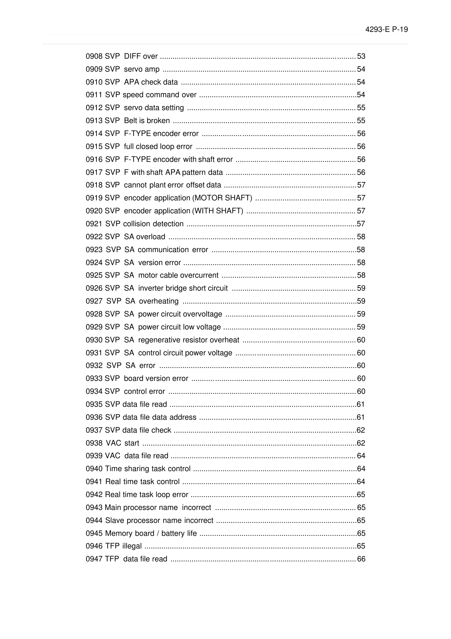
SECTION 3 ALARM P
0908 SVP DIFF over ............................................................................................. 53
0909 SVP servo amp ............................................................................................ 54
0910 SVP APA check data ................................................................................... 54
0911 SVP speed command over ...........................................................................54
0912 SVP servo data setting ................................................................................ 55
0913 SVP Belt is broken ....................................................................................... 55
0914 SVP F-TYPE encoder error ......................................................................... 56
0915 SVP full closed loop error ............................................................................ 56
0916 SVP F-TYPE encoder with shaft error ......................................................... 56
0917 SVP F with shaft APA pattern data .............................................................. 56
0918 SVP cannot plant error offset data ............................................................... 57
0919 SVP encoder application (MOTOR SHAFT) ................................................ 57
0920 SVP encoder application (WITH SHAFT) .................................................... 57
0921 SVP collision detection .................................................................................57
0922 SVP SA overload ......................................................................................... 58
0923 SVP SA communication error .....................................................................58
0924 SVP SA version error .................................................................................. 58
0925 SVP SA motor cable overcurrent ................................................................58
0926 SVP SA inverter bridge short circuit ...........................................................59
0927 SVP SA overheating ...................................................................................59
0928 SVP SA power circuit overvoltage .............................................................. 59
0929 SVP SA power circuit low voltage ............................................................... 59
0930 SVP SA regenerative resistor overheat ...................................................... 60
0931 SVP SA control circuit power voltage ......................................................... 60
0932 SVP SA error ..............................................................................................60
0933 SVP board version error .............................................................................. 60
0934 SVP control error .........................................................................................60
0935 SVP data file read .........................................................................................61
0936 SVP data file data address ...........................................................................61
0937 SVP data file check .......................................................................................62
0938 VAC start ......................................................................................................62
0939 VAC data file read ........................................................................................ 64
0940 Time sharing task control ..............................................................................64
0941 Real time task control ...................................................................................64
0942 Real time task loop error ...............................................................................65
0943 Main processor name incorrect ................................................................... 65
0944 Slave processor name incorrect ...................................................................65
0945 Memory board / battery life ...........................................................................65
0946 TFP illegal .....................................................................................................65
0947 TFP data file read ........................................................................................ 66
Page 27
4293-E P-20
SECTION 3 ALARM P
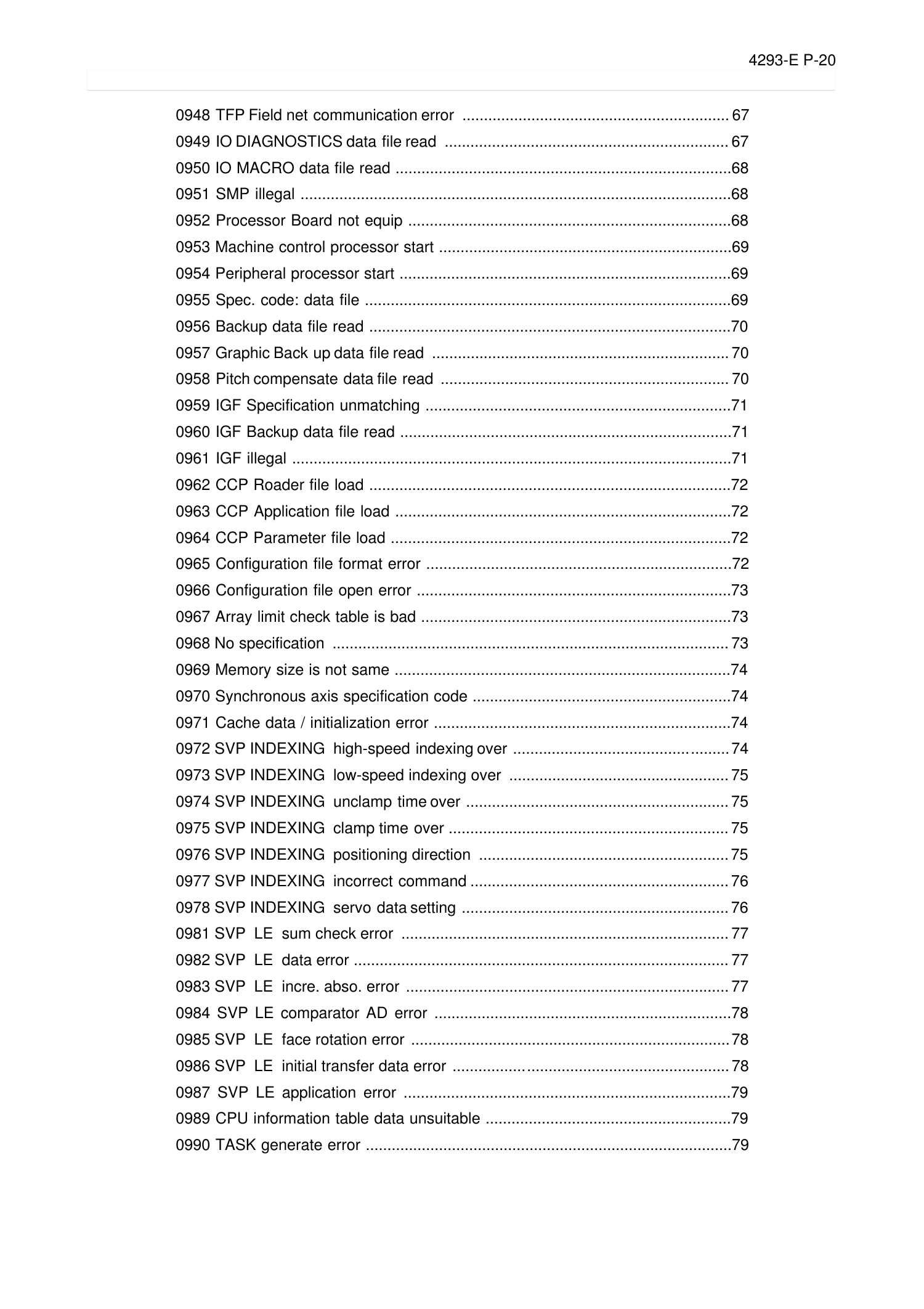
0948 TFP Field net communication error .............................................................. 67
0949 IO DIAGNOSTICS data file read .................................................................. 67
0950 IO MACRO data file read ..............................................................................68
0951 SMP illegal ....................................................................................................68
0952 Processor Board not equip ...........................................................................68
0953 Machine control processor start ....................................................................69
0954 Peripheral processor start .............................................................................69
0955 Spec. code: data file .....................................................................................69
0956 Backup data file read ....................................................................................70
0957 Graphic Back up data file read ..................................................................... 70
0958 Pitch compensate data file read ................................................................... 70
0959 IGF Specification unmatching .......................................................................71
0960 IGF Backup data file read .............................................................................71
0961 IGF illegal ......................................................................................................71
0962 CCP Roader file load ....................................................................................72
0963 CCP Application file load ..............................................................................72
0964 CCP Parameter file load ...............................................................................72
0965 Configuration file format error .......................................................................72
0966 Configuration file open error .........................................................................73
0967 Array limit check table is bad ........................................................................73
0968 No specification ............................................................................................ 73
0969 Memory size is not same ..............................................................................74
0970 Synchronous axis specification code ............................................................74
0971 Cache data / initialization error .....................................................................74
0972 SVP INDEXING high-speed indexing over .................................................. 74
0973 SVP INDEXING low-speed indexing over ................................................... 75
0974 SVP INDEXING unclamp time over ............................................................. 75
0975 SVP INDEXING clamp time over ................................................................. 75
0976 SVP INDEXING positioning direction .......................................................... 75
0977 SVP INDEXING incorrect command ............................................................ 76
0978 SVP INDEXING servo data setting .............................................................. 76
0981 SVP LE sum check error ............................................................................ 77
0982 SVP LE data error ....................................................................................... 77
0983 SVP LE incre. abso. error ........................................................................... 77
0984 SVP LE comparator AD error .....................................................................78
0985 SVP LE face rotation error ..........................................................................78
0986 SVP LE initial transfer data error ................................................................ 78
0987 SVP LE application error ............................................................................79
0989 CPU information table data unsuitable .........................................................79
0990 TASK generate error .....................................................................................79
Page 28
4293-E P-21
SECTION 3 ALARM P
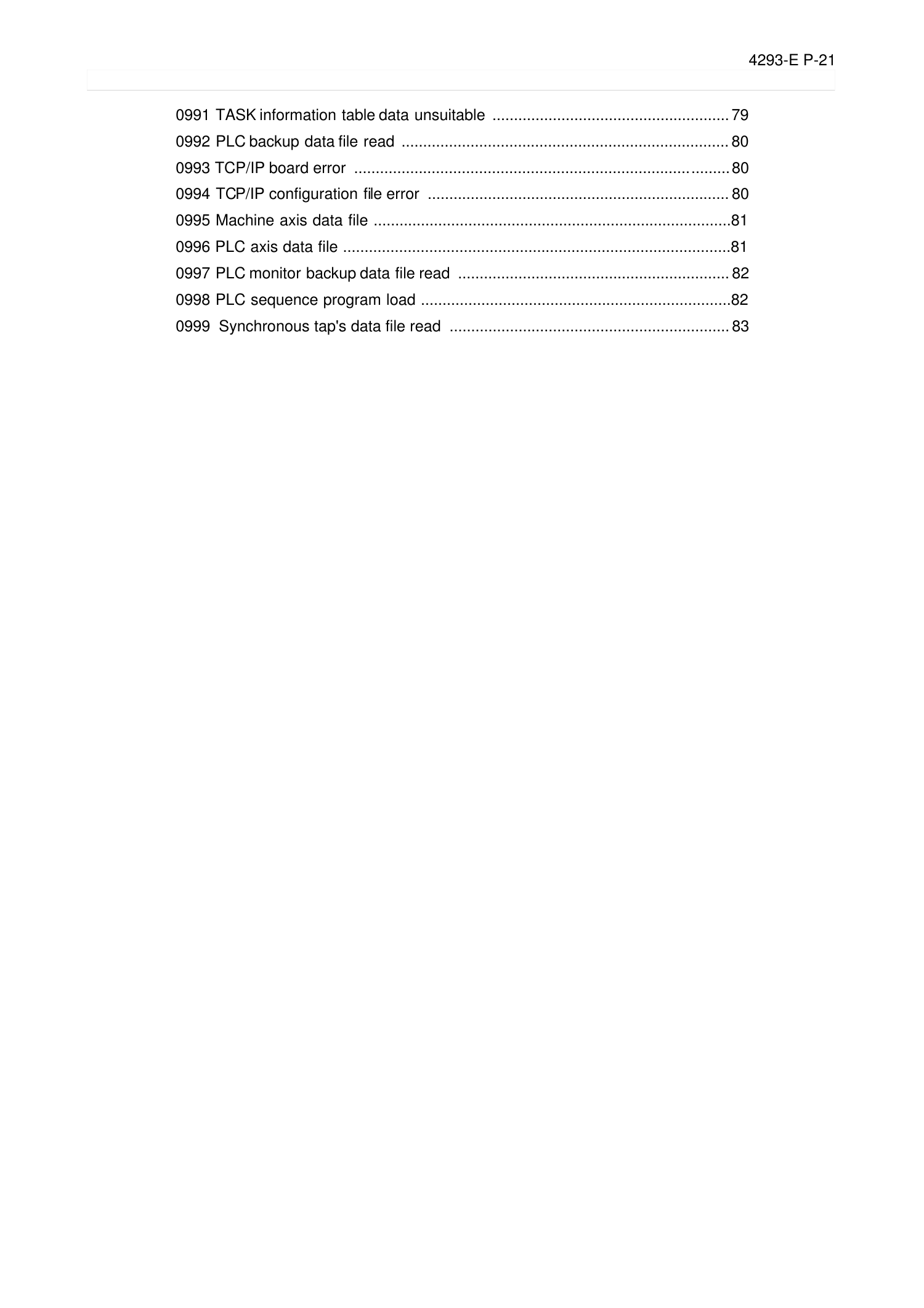
0991 TASK information table data unsuitable ....................................................... 79
0992 PLC backup data file read ............................................................................ 80
0993 TCP/IP board error ....................................................................................... 80
0994 TCP/IP configuration file error ...................................................................... 80
0995 Machine axis data file ...................................................................................81
0996 PLC axis data file ..........................................................................................81
0997 PLC monitor backup data file read ............................................................... 82
0998 PLC sequence program load ........................................................................82
0999 Synchronous tap's data file read ................................................................. 83
Page 29
4293-E P-22
SECTION 3 ALARM P
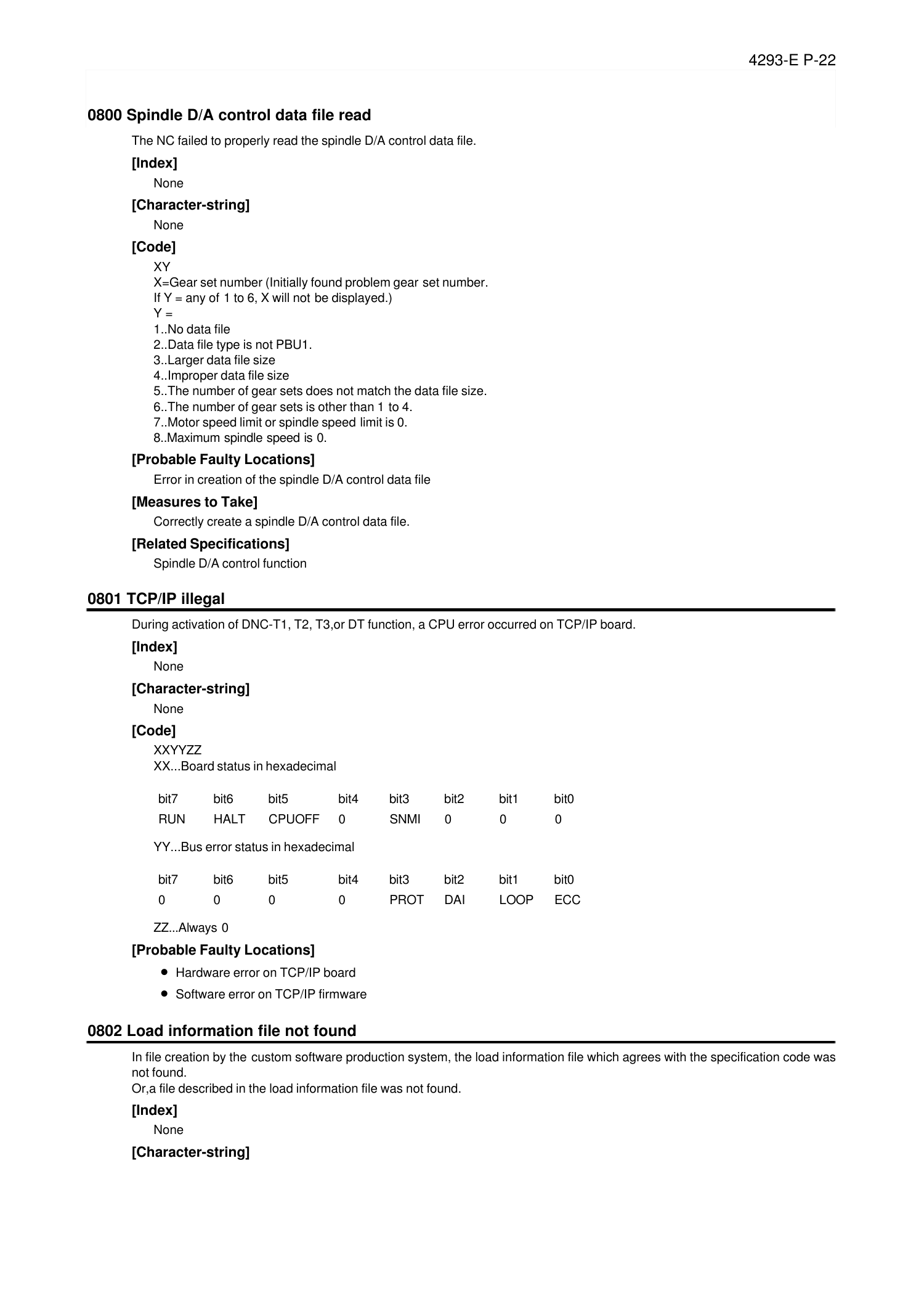
0800 Spindle D/A control data file read
Eeoemale2001
The NC failed to properly read the spindle D/A control data file.
[Index]
None
[Character-string]
None
[Code]
XY
X=Gear set number (Initially found problem gear set number.
If Y = any of 1 to 6, X will not be displayed.)
Y =
1..No data file
2..Data file type is not PBU1.
3..Larger data file size
4..Improper data file size
5..The number of gear sets does not match the data file size.
6..The number of gear sets is other than 1 to 4.
7..Motor speed limit or spindle speed limit is 0.
8..Maximum spindle speed is 0.
[Probable Faulty Locations]
Error in creation of the spindle D/A control data file
[Measures to Take]
Correctly create a spindle D/A control data file.
[Related Specifications]
Spindle D/A control function
0801 TCP/IP illegal
Eeoemale2002
During activation of DNC-T1, T2, T3,or DT function, a CPU error occurred on TCP/IP board.
[Index]
None
[Character-string]
None
[Code]
XXYYZZ
XX...Board status in hexadecimal
YY...Bus error status in hexadecimal
ZZ...Always 0
[Probable Faulty Locations]
• Hardware error on TCP/IP board
• Software error on TCP/IP firmware
0802 Load information file not found
Eeoemale2003
In file creation by the custom software production system, the load information file which agrees with the specification code was
not found.
Or,a file described in the load information file was not found.
[Index]
None
[Character-string]
bit7 bit6 bit5 bit4 bit3 bit2 bit1 bit0
RUN HALT CPUOFF 0 SNMI 0 0 0
bit7 bit6 bit5 bit4 bit3 bit2 bit1 bit0
0 0 0 0 PROT DAI LOOP ECC
Page 30
4293-E P-23
SECTION 3 ALARM P
Problem file name
[Code]
None
However, there may be a case where an error message is output in the console line.
[Probable Faulty Locations]
Defective installation, software production error, or specification code error
[Measures to Take]
• Reinstall the software.
• Reissue the install floppy disk.
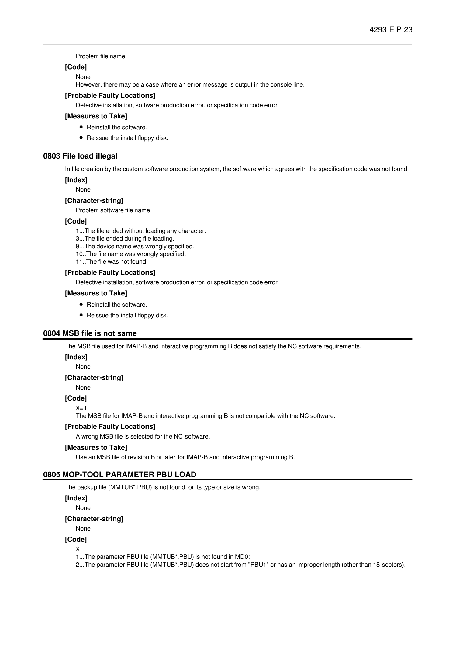
0803 File load illegal
Eeoemale2004
In file creation by the custom software production system, the software which agrees with the specification code was not found
[Index]
None
[Character-string]
Problem software file name
[Code]
1...The file ended without loading any character.
3...The file ended during file loading.
9...The device name was wrongly specified.
10..The file name was wrongly specified.
11..The file was not found.
[Probable Faulty Locations]
Defective installation, software production error, or specification code error
[Measures to Take]
• Reinstall the software.
• Reissue the install floppy disk.
0804 MSB file is not same
Eeoemale2005
The MSB file used for IMAP-B and interactive programming B does not satisfy the NC software requirements.
[Index]
None
[Character-string]
None
[Code]
X=1
The MSB file for IMAP-B and interactive programming B is not compatible with the NC software.
[Probable Faulty Locations]
A wrong MSB file is selected for the NC software.
[Measures to Take]
Use an MSB file of revision B or later for IMAP-B and interactive programming B.
0805 MOP-TOOL PARAMETER PBU LOAD
Eeoemale2006
The backup file (MMTUB*.PBU) is not found, or its type or size is wrong.
[Index]
None
[Character-string]
None
[Code]
X
1...The parameter PBU file (MMTUB*.PBU) is not found in MD0:
2...The parameter PBU file (MMTUB*.PBU) does not start from "PBU1" or has an improper length (other than 18 sectors).
Page 31
4293-E P-24
SECTION 3 ALARM P
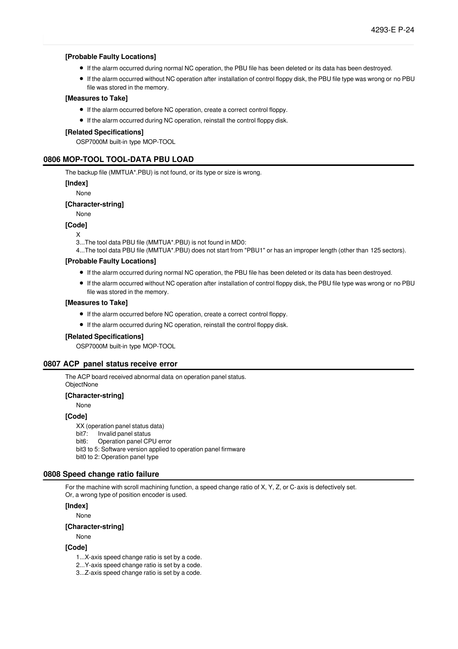
[Probable Faulty Locations]
• If the alarm occurred during normal NC operation, the PBU file has been deleted or its data has been destroyed.
• If the alarm occurred without NC operation after installation of control floppy disk, the PBU file type was wrong or no PBU
file was stored in the memory.
[Measures to Take]
• If the alarm occurred before NC operation, create a correct control floppy.
• If the alarm occurred during NC operation, reinstall the control floppy disk.
[Related Specifications]
OSP7000M built-in type MOP-TOOL
0806 MOP-TOOL TOOL-DATA PBU LOAD
Eeoemale2007
The backup file (MMTUA*.PBU) is not found, or its type or size is wrong.
[Index]
None
[Character-string]
None
[Code]
X
3...The tool data PBU file (MMTUA*.PBU) is not found in MD0:
4...The tool data PBU file (MMTUA*.PBU) does not start from "PBU1" or has an improper length (other than 125 sectors).
[Probable Faulty Locations]
• If the alarm occurred during normal NC operation, the PBU file has been deleted or its data has been destroyed.
• If the alarm occurred without NC operation after installation of control floppy disk, the PBU file type was wrong or no PBU
file was stored in the memory.
[Measures to Take]
• If the alarm occurred before NC operation, create a correct control floppy.
• If the alarm occurred during NC operation, reinstall the control floppy disk.
[Related Specifications]
OSP7000M built-in type MOP-TOOL
0807 ACP panel status receive error
Eeoemale2008
The ACP board received abnormal data on operation panel status.
ObjectNone
[Character-string]
None
[Code]
XX (operation panel status data)
bit7: Invalid panel status
bit6: Operation panel CPU error
bit3 to 5: Software version applied to operation panel firmware
bit0 to 2: Operation panel type
0808 Speed change ratio failure
Eeoemale2009
For the machine with scroll machining function, a speed change ratio of X, Y, Z, or C-axis is defectively set.
Or, a wrong type of position encoder is used.
[Index]
None
[Character-string]
None
[Code]
1...X-axis speed change ratio is set by a code.
2...Y-axis speed change ratio is set by a code.
3...Z-axis speed change ratio is set by a code.
Page 32
4293-E P-25
SECTION 3 ALARM P
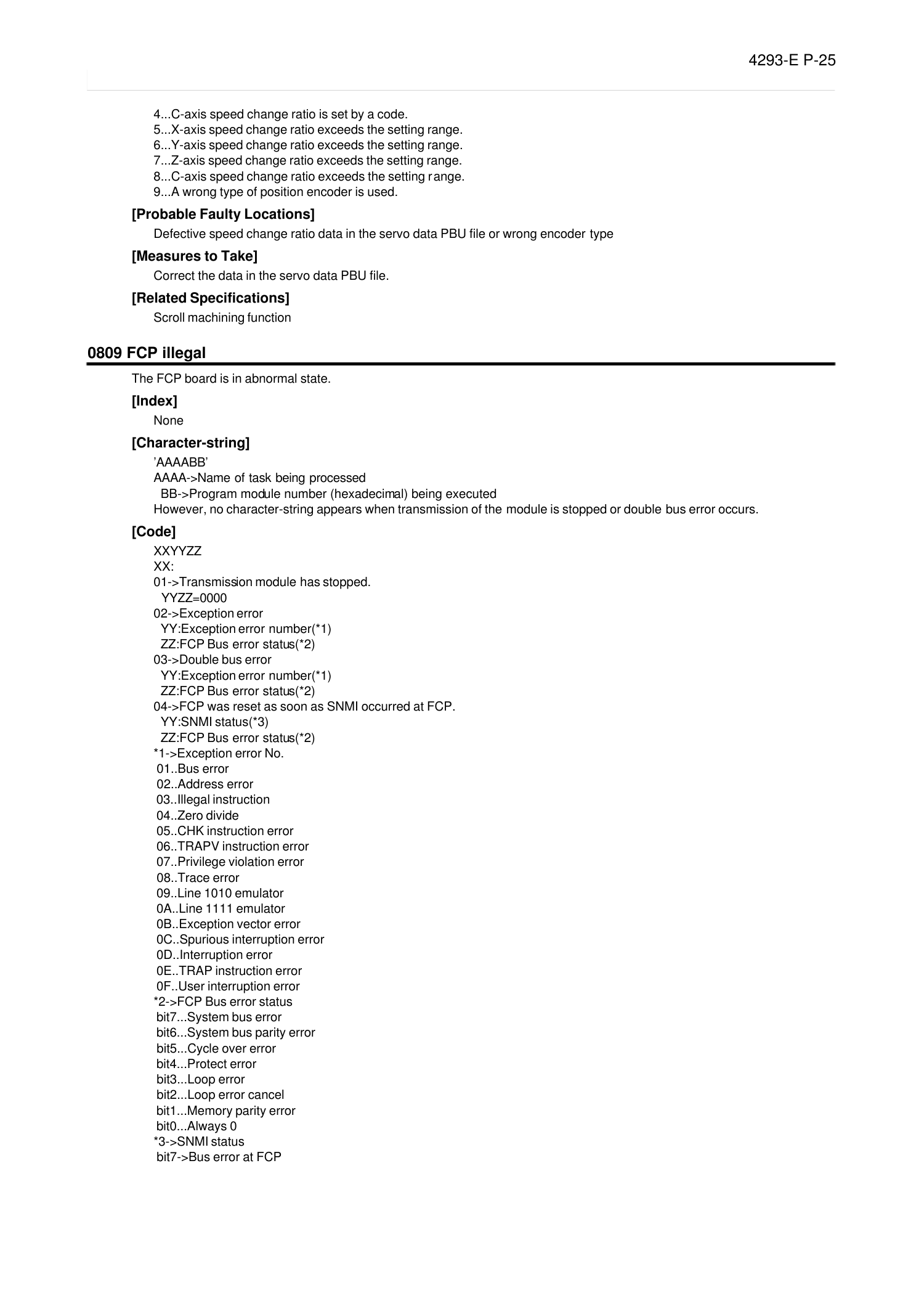
4...C-axis speed change ratio is set by a code.
5...X-axis speed change ratio exceeds the setting range.
6...Y-axis speed change ratio exceeds the setting range.
7...Z-axis speed change ratio exceeds the setting range.
8...C-axis speed change ratio exceeds the setting range.
9...A wrong type of position encoder is used.
[Probable Faulty Locations]
Defective speed change ratio data in the servo data PBU file or wrong encoder type
[Measures to Take]
Correct the data in the servo data PBU file.
[Related Specifications]
Scroll machining function
0809 FCP illegal
Eeoemale2010
The FCP board is in abnormal state.
[Index]
None
[Character-string]
’AAAABB’
AAAA->Name of task being processed
BB->Program module number (hexadecimal) being executed
However, no character-string appears when transmission of the module is stopped or double bus error occurs.
[Code]
XXYYZZ
XX:
01->Transmission module has stopped.
YYZZ=0000
02->Exception error
YY:Exception error number(*1)
ZZ:FCP Bus error status(*2)
03->Double bus error
YY:Exception error number(*1)
ZZ:FCP Bus error status(*2)
04->FCP was reset as soon as SNMI occurred at FCP.
YY:SNMI status(*3)
ZZ:FCP Bus error status(*2)
*1->Exception error No.
01..Bus error
02..Address error
03..Illegal instruction
04..Zero divide
05..CHK instruction error
06..TRAPV instruction error
07..Privilege violation error
08..Trace error
09..Line 1010 emulator
0A..Line 1111 emulator
0B..Exception vector error
0C..Spurious interruption error
0D..Interruption error
0E..TRAP instruction error
0F..User interruption error
*2->FCP Bus error status
bit7...System bus error
bit6...System bus parity error
bit5...Cycle over error
bit4...Protect error
bit3...Loop error
bit2...Loop error cancel
bit1...Memory parity error
bit0...Always 0
*3->SNMI status
bit7->Bus error at FCP
Page 33

4293-E P-26
SECTION 3 ALARM P
bit6->FCP executed SNMI command.
bit5->Oscillator module stopped oscillation.
bit4->Always 0
bit3->Always 0
bit2->Always 0
bit1->Always 0
bit0->Always 0
0810 NCIO data file read
Eeoemale2011
The NC failed to read I/O data file.
[Index]
None
[Character-string]
None
[Code]
I/O data file load status (in hexadecimal)
2->File open error (no file)
3->File read error (no data)
4->File attribute error (not PBU1)
5->File close error
6->File size error (smaller size)
7->File size error (larger size)
100->Wrong PLC machine type
200->Wrong PLC class
300->Wrong file version
[Measures to Take]
Consult the machine maker.
0811 FCP IO link communication error
Eeoemale2012
A communication error occurred in the I/O link on FCP board.
[Index]
None
[Character-string]
None
[Code]
XxYYZZZZ
XX:
01->Channel number where FCP board error was detected
x=0->Errors (other than below)
x=1->Faulty connection of optical fibers
x=2->Initialization error
YY:
bit7->Double transmission error
bit6->Double reception error
bit5->Format error
bit4->CRC error
bit3->Parity error (transmission/reception buffer)
bit2->Disconnection command detected
bit1->Time out error
bit0->Undefined
ZZZZ:
bit15->Slave station error detected
bit14->Undefined
bit13->Undefined
bit12->Start bit error
bit11->Stop bit error
bit10->Undefined
bit9, 8->00 ... Master station, slave station
->01 ... Repeater No. 1
->10 ... Repeater No. 2
bit7 to 0->Slave station number where the error was detected (master station: $00)
Page 34
4293-E P-27
SECTION 3 ALARM P
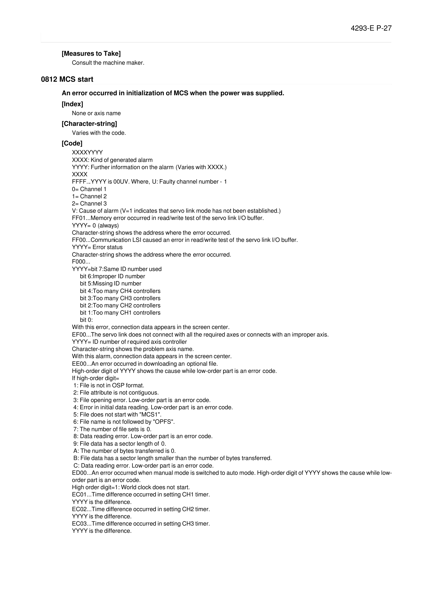
[Measures to Take]
Consult the machine maker.
0812 MCS start
Eeoemale2013
An error occurred in initialization of MCS when the power was supplied.
[Index]
None or axis name
[Character-string]
Varies with the code.
[Code]
XXXXYYYY
XXXX: Kind of generated alarm
YYYY: Further information on the alarm (Varies with XXXX.)
XXXX
FFFF...YYYY is 00UV. Where, U: Faulty channel number - 1
0= Channel 1
1= Channel 2
2= Channel 3
V: Cause of alarm (V=1 indicates that servo link mode has not been established.)
FF01...Memory error occurred in read/write test of the servo link I/O buffer.
YYYY= 0 (always)
Character-string shows the address where the error occurred.
FF00...Communication LSI caused an error in read/write test of the servo link I/O buffer.
YYYY= Error status
Character-string shows the address where the error occurred.
F000...
YYYY=bit 7:Same ID number used
bit 6:Improper ID number
bit 5:Missing ID number
bit 4:Too many CH4 controllers
bit 3:Too many CH3 controllers
bit 2:Too many CH2 controllers
bit 1:Too many CH1 controllers
bit 0:
With this error, connection data appears in the screen center.
EF00...The servo link does not connect with all the required axes or connects with an improper axis.
YYYY= ID number of required axis controller
Character-string shows the problem axis name.
With this alarm, connection data appears in the screen center.
EE00...An error occurred in downloading an optional file.
High-order digit of YYYY shows the cause while low-order part is an error code.
If high-order digit=
1: File is not in OSP format.
2: File attribute is not contiguous.
3: File opening error. Low-order part is an error code.
4: Error in initial data reading. Low-order part is an error code.
5: File does not start with "MCS1".
6: File name is not followed by "OPFS".
7: The number of file sets is 0.
8: Data reading error. Low-order part is an error code.
9: File data has a sector length of 0.
A: The number of bytes transferred is 0.
B: File data has a sector length smaller than the number of bytes transferred.
C: Data reading error. Low-order part is an error code.
ED00...An error occurred when manual mode is switched to auto mode. High-order digit of YYYY shows the cause while low-
order part is an error code.
High order digit=1: World clock does not start.
EC01...Time difference occurred in setting CH1 timer.
YYYY is the difference.
EC02...Time difference occurred in setting CH2 timer.
YYYY is the difference.
EC03...Time difference occurred in setting CH3 timer.
YYYY is the difference.
Page 35
4293-E P-28
SECTION 3 ALARM P
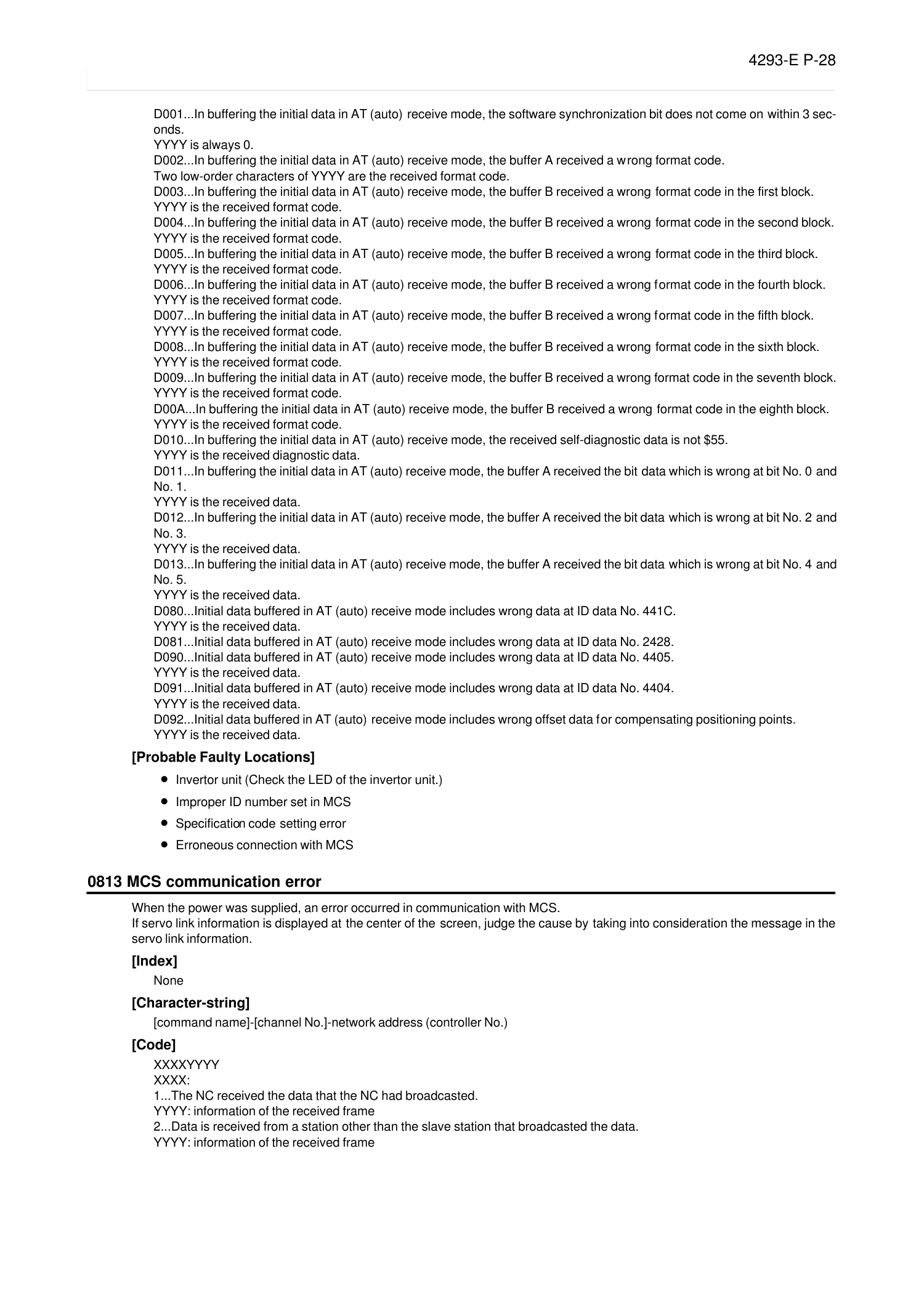
D001...In buffering the initial data in AT (auto) receive mode, the software synchronization bit does not come on within 3 sec-
onds.
YYYY is always 0.
D002...In buffering the initial data in AT (auto) receive mode, the buffer A received a wrong format code.
Two low-order characters of YYYY are the received format code.
D003...In buffering the initial data in AT (auto) receive mode, the buffer B received a wrong format code in the first block.
YYYY is the received format code.
D004...In buffering the initial data in AT (auto) receive mode, the buffer B received a wrong format code in the second block.
YYYY is the received format code.
D005...In buffering the initial data in AT (auto) receive mode, the buffer B received a wrong format code in the third block.
YYYY is the received format code.
D006...In buffering the initial data in AT (auto) receive mode, the buffer B received a wrong format code in the fourth block.
YYYY is the received format code.
D007...In buffering the initial data in AT (auto) receive mode, the buffer B received a wrong format code in the fifth block.
YYYY is the received format code.
D008...In buffering the initial data in AT (auto) receive mode, the buffer B received a wrong format code in the sixth block.
YYYY is the received format code.
D009...In buffering the initial data in AT (auto) receive mode, the buffer B received a wrong format code in the seventh block.
YYYY is the received format code.
D00A...In buffering the initial data in AT (auto) receive mode, the buffer B received a wrong format code in the eighth block.
YYYY is the received format code.
D010...In buffering the initial data in AT (auto) receive mode, the received self-diagnostic data is not $55.
YYYY is the received diagnostic data.
D011...In buffering the initial data in AT (auto) receive mode, the buffer A received the bit data which is wrong at bit No. 0 and
No. 1.
YYYY is the received data.
D012...In buffering the initial data in AT (auto) receive mode, the buffer A received the bit data which is wrong at bit No. 2 and
No. 3.
YYYY is the received data.
D013...In buffering the initial data in AT (auto) receive mode, the buffer A received the bit data which is wrong at bit No. 4 and
No. 5.
YYYY is the received data.
D080...Initial data buffered in AT (auto) receive mode includes wrong data at ID data No. 441C.
YYYY is the received data.
D081...Initial data buffered in AT (auto) receive mode includes wrong data at ID data No. 2428.
D090...Initial data buffered in AT (auto) receive mode includes wrong data at ID data No. 4405.
YYYY is the received data.
D091...Initial data buffered in AT (auto) receive mode includes wrong data at ID data No. 4404.
YYYY is the received data.
D092...Initial data buffered in AT (auto) receive mode includes wrong offset data for compensating positioning points.
YYYY is the received data.
[Probable Faulty Locations]
• Invertor unit (Check the LED of the invertor unit.)
• Improper ID number set in MCS
• Specification code setting error
• Erroneous connection with MCS
0813 MCS communication error
Eeoemale2014
When the power was supplied, an error occurred in communication with MCS.
If servo link information is displayed at the center of the screen, judge the cause by taking into consideration the message in the
servo link information.
[Index]
None
[Character-string]
[command name]-[channel No.]-network address (controller No.)
[Code]
XXXXYYYY
XXXX:
1...The NC received the data that the NC had broadcasted.
YYYY: information of the received frame
2...Data is received from a station other than the slave station that broadcasted the data.
YYYY: information of the received frame
Page 36
4293-E P-29
SECTION 3 ALARM P
3...The received data size is 2 bytes or less.
YYYY: always 0
4...Data is received from a station other than the slave station that sent the date.
YYYY: information of the received frame
5...The NC received the data that the NC had transmitted in a way other than broadcasting.
YYYY: information of the received frame
6...Data is received from a the station of which network address is 0.
YYYY: information of the received frame
7...Data reception response is not sent within 1 or 0.1 second after data transmission.
YYYY: Always 0
’SI’ command is specified before at least one MCS is normally activated in the link or before the power is supplied.
Open the box and check the LEDs of all the MCS units connected to the error-caused channel.
Normal units are indicated with ’22’.
8...Data transmission does not end within 0.1 second.
YYYY: Always 0
9...Communication error occurred after reception of data.
YYYY: Error status
A...Communication error occurred while the NC was waiting for data reception or immediately after data transmission.
YYYY: Error status
B...Communication error occurred while the NC was waiting for data transmission.
YYYY: Error status
C...Data transmission was attempted during data transmission.
YYYY: NC operation status
D...Data transmission was attempted in the state of communication error.
YYYY: Error status
E...An error command was received.
Two high-order digits of YYYY are a code (45: exception; 41: alarm; 57: warning; 54: error) while low-order digits are the
number.
[Refer to the shake-hand communication error list (5-10) in external specification for MCS controller function.]
100...The received first 2 bytes are improper as a response to the transmitted data.
YYYY: Received first 2 bytes
101...The received data size is improper as a response to the transmitted data.High-order digits of YYYY is the received data
size while the low-order half is a normal value.
102...Data No. 1 attached to the received data is improper.
YYYY: Two high-order bytes of the data judged to be improper
SI command: slave station connection No.
AS command: slave station connection No.
ID command: communication code + auxiliary code
103...Data No. 2 attached to the received data is improper.
YYYY: Two high-order bytes of the data judged to be improper
SI command: cumulative relay time
ID command: data ID
104...Data No. 3 attached to the received data is improper.
YYYY: two high-order bytes of the data judged to be improper
ID command: reserved
105...Data No. 4 attached to the received data is improper.
YYYY: Two high-order bytes of the data judged to be improper
ID command: ID data (4 bytes or less)
106...Data No. 5 attached to the received data is improper.
YYYY: Two high-order bytes of the data judged to be improper
SI command: The number of controllers
ID command: ID data (8 bytes)
200...Data sizes differ from those specified with ID numbers.
Faulty software
[Probable Faulty Locations]
• Invertor unit (Check the LED of the invertor unit.)
• FCP board
• MCS connection error
• MCS connection cable is faulty
• Faulty software
0814 MCS data file
Eeoemale2015
When the power was supplied, an error occurred in reading or transferring the servo link data file.
Or, the data file includes abnormal data.
Page 37
4293-E P-30
SECTION 3 ALARM P
[Index]
[Character-string]
[axis name] [device name] [file name] [character-string] or none
[Code]
XYZZAAAA
X: Axis kind; Y: Rough classification; ZZ: Minute
classification; AAAA: Data
X:1= NC-controlled axis
2= spindle
3= PLC-controlled axis
Y:0= Error in reading servo data file
ZZ:
01= Error occurred in retrieval of the file. AAAA=error code
AAAA indicates that the data file does not exist at 000B: or the required axis data does not exists in the file.
02= File attribute is not contiguous.
03= File is not in OSP format.
04= File opening error. AAAA=error code
05= File data reading error. AAAA=error code
06= File does not start with "PBU1".
07= File name is not followed by "M1".
08= The relevant axis data has exceeded the maximum number of data sets stored in the file before the specified number of
data sets are transferred.
09= File closing error. AAAA=error code
0A= A set of data size is larger than 8 sectors. AAAA=number of data sectors
0B= Data reading error. AAAA=error code
0C= The data file does not contain the previously specified number of data sets.
0D= The data serial number does not match.
0E= The data type does not match.
0F= The whole number of data sets does not match.
10= File closing error. AAAA=error code
11= Servo data does not exist in the file where NC axis data exists.
Y:1= Error in checking servo data file
ZZ:
01= The NC axis data file of NC axis control for heavy workpiece specification is not found.
02= Axis specification (rotary or limited) or unit system does not match. AAAA=axis specification data
03= Acceleration/deceleration method does not match.
04= Inductosyn is not provided.
05= The number of data sets is abnormal (the number of spindle data sets is not within 1 to 32). AAAA=the number of data
sets
06= The speed-time constant characteristic data includes faulty data with reversed inequality.
AAAA= Two high-order digits show the axis number while low-order digits are the error content.
High-order AA:
00-> X-axis
01-> Y-axis
02-> Z-axis
03-> 4th axis
04-> 5th axis
Low-order AA:
11-> FT1max=0
12-> FT1max<FT1min
13-> FT1max=FT1min and T1max<T1min
14-> FT1max>FT1min and T1max<T1min
21-> FT2max=0 (FT2max is determined by internal calculation.)
22-> FT2max<FT2min
23-> FT2max=FT2min and T2max<T2min
24-> FT2max>FT2min and T2max<T2min
07= The servo data to be used with the NC axis data for heavy workpiece specification is not found.
[Probable Faulty Locations]
Axis data file
0815 PLC Real time task loop error
Eeoemale2016
The real time task indicated by the character-string failed to end within the preset processing time.
[Index]
None
Page 38
4293-E P-31
SECTION 3 ALARM P
[Character-string]
AAAABB
AAAA-> Task name being processed when the loop error was detected.
BB-> Program module number being executed (hexadecimal)
[Code]
XXXXXXXX-> Program counter value (hexadecimal) at the time of error detection
[Probable Faulty Locations]
• Level 2 or level 3 task in the PLC sequence program failed to end processing within the preset time.
• Timing error of synchronous signal
• Wrongly set synchronous signal frequency
• Faulty software
0816 PLC initial error
Eeoemale2017
An error was detected in the checking process for activating the PLC.
[Index]
None
[Character-string]
None
[Code]
XX
=1...NC-PLC synchronous parameter is not found.
[Measures to Take]
Consult the machine maker.
0817 MCS Error
Eeoemale2018
An error occurred under the control by MCS.
[Index]
Axis name or none
[Character-string]
None
[Code]
XXZZAAAA
XYZZ: 0
AAAA:
1= Processing does not end within 5 seconds after MCS reset 1.
2= Processing does not end within 5 seconds after MCS reset 2.
3 = Processing does not end within 5 seconds after PLC reset processing 1.
4 = Processing does not end within 5 seconds after PLC reset processing 2.
X: 1 to 3
X: Channel number
YZZAAAA: Communication error status
[Probable Faulty Locations]
• Faulty MCS controller
• Faulty servo link on FCP board
• Faulty software
0818 ADP START
Eeoemale2019
An alarm occurred while the AD conversion processor board was initialized after power ON.
[Index]
None
[Character-string]
None
[Code]
Page 39
4293-E P-32
SECTION 3 ALARM P
X
X=1:Synchronous counter value remains 1.
X=2:A system alarm occurred when the synchronous counter value was 1.
X=3:Synchronous counter value remains 3.
X=4:A system alarm occurred when the synchronous counter value was 3.
[Probable Faulty Locations]
1 ADP(AD conversion processor board)
[Measures to Take]
Replace the ADP(AD conversion processor board).
[Related Specifications]
Thermal deviation compensation
0829 SPMC Program load
Eeoemale2020
Error occurred when loading program of SUPER MAIN CARD(SPMC).
[Code]
XYYZAAAA
X: Module number of load program
YY: Subroutine number in module
Z: Error number in subroutine
AAAA: A numerical value is entered as the case may be.
[Probable Faulty Locations]
• Defective installation or software production error
• Faulty software
• Faulty SPMC
• Faulty SUPER MAIN BOARD(SPMB)
0830 SPMC Execution stop
Eeoemale2021
A replying value to the execution beginning request, the reset request, or the data transfar request from SUPER MAIN CARD
(SPMC) was not prescribed one.
[Code]
XXYY
XX=10: No reply was sent within 20 seconds after sending the execution beginning request to SPMC.
XX=18: No reply was sent within 20 seconds after sending the reset request to SPMC.
XX=20: The replying value from SPMC to the data transfar request was not prescribed one.
YY: In case of 32 to 61, the possibility that the exception occurs in SPMC is high and ($YY-$32) shows an exception kind.
In the case except it, the possibility of faulty software is high.
[Probable Faulty Locations]
• Faulty SPMC
• Faulty SUPER MAIN BOARD(SPMB)
• Faulty software
0831 SPM Exception processing
Eeoemale2022
Fatal abnormality has occurred in processing by hardware or software of SUPER MAIN CARD(SPMC).
[Code]
200->Machine Check Exception
300->Data Access Exception
400->Instruction Access Exception
600->Alignment Exception
700->Program Exception
800->Floating-Point Unavailable Exception
D00->Trace Exception
1000->Instruction Translation Miss Exception
1100->Data Load Translation Miss Exception
1200->Data Store Translation Miss Exception
1300->Instruction Address Breakpoint Exception
1400->System Management Interrupt
Page 40
4293-E P-33
SECTION 3 ALARM P
[Probable Faulty Locations]
• Faulty SPMC
• Faulty SUPER MAIN BOARD(SPMB)
• Faulty software
0832 SPM System Call error
Eeoemale2023
In the system call processing with the SUPER MAIN CARD(SPMC), error was detected.
[Code]
2XXXXXXX
XXXXXXX: Error code which was returned from system call.
[Probable Faulty Locations]
Faulty software
0833 MCS Option-program-file not send
Eeoemale2024
The optional program file for MCS has not been transferred to the MCS.
[Index]
Axis name or none
[Character-string]
None
[Code]
None
[Probable Faulty Locations]
•
MCS optional program file has not been transferred.
• MCS optional program file is not found.
• MCS optional program file does not contain the program that matches the MCS software version.
[Measures to Take]
• Install the MCS optional program file.
• Change the MCS optional program file.
0834 MCS Servo-data error
Eeoemale2025
Erroneous servo data has been transferred to MCS.
[Index]
Axis name or none
[Character-string]
None
[Code]
XXXXYYZZ
XXXX = ID number
YY = Parameter number
ZZ = Error content
01: Out of setting range
02: Set timing error
03: No data transfer
04: Calculation error
05: Others
[Probable Faulty Locations]
• The servo data file does not match the MCS software version.
• NC software
[Measures to Take]
Change the servo data file.
Page 41
4293-E P-34
SECTION 3 ALARM P
0835 MCS Communication
Eeoemale2026
An error occurred during shake-hand communication with MCS.
[Index]
Axis name or none
[Character-string]
Shake-hand communication error number (2 digits), error data (8 digits), and [command name]-[channel number]-net
address (controller number)
[Code]
None
[Probable Faulty Locations]
•
Faulty application software
• Faulty MCS software
[Measures to Take]
• Change the application software.
• Change the MCS software.
0840 Super-Hi-NC specification mismatch
Eeoemale2027
The NC specifications do not meet the requirements for the Super-Hi-NC function or the NURBS command specification.
[Code]
1-> The 2nd main board is not the high-speed main board. Or, the 3rd main board is not the super main board.
[Probable Faulty Locations]
High-speed main board or super main board
[Measures to Take]
Change the 2nd main board to a high-speed main board, and the 3rd main board to a super main board.
[Relating Specification]
Super-Hi-NC Function, NURBS Command Specification
0850 MCS Undefined alarm number
Eeoemale2028
The MCS caused an error related with axis control.
[Index]
Axis name or none (spindle)
[Character-string]
Alarm number in decimal
[Code]
Alarm code
[Probable Faulty Locations]
•
Depends on the number indicated in the character-string.
• Inform us of the code and the character string.
0851 MCS Exception processing
Eeoemale2029
A fatal alarm occurred while the MCS invertor unit and MCS software are executing their processing.
[Index]
Axis name or none (spindle)
[Character-string]
Cause of alarm detected
"#1"-> Control board error
"#2"-> Voltage drop of +-12 V battery for control board
"#3"-> OPF error
"#11"-> Voltage drop of 5 V battery for control board
"#12"-> Invertor bridge shorted
"#13"-> IPM protective function activated
"#14"-> Motor overcurrent
Page 42
4293-E P-35
SECTION 3 ALARM P
"#20"-> INT loop error
"#21"-> INT5 loop error
"#22"-> INT4 loop error
"#23"-> INT3 loop error
"#24"-> INT2 loop error
"#25"-> INT1 loop error
"#26"-> Access denied
"#27"-> Ram check error in initialization
"#28"-> Party error
"#29"-> Watchdog error
"#30"-> IRQ7 interruption
"#31"-> NMI interruption
"#32"-> General illegal command
"#33"-> Slot illegal command
"#34"-> CPU address error
"#35"-> DMA address error
"#36"-> Undefined trap error
"#37"-> Undefined interruption
"#38"-> DMAC
"#39"-> ITU
"#40"-> SCI
"#41"-> REF
"#42"-> A/D
"#43"-> System reserved
"#44"-> User break
[Code]
In the case of #1, the code shows the error content of the control board.
In the case of #3, the code shows the error content of the optional program file.
1: Identification code "OPF1" error
2: End code "ED" error
3: Sum check error
4: Board name error
In the case of #11-14, #20-21, #25-26 and #30-31, the code shows the data in the error status register.
[Probable Faulty Locations]
In the case of #1,
•
Invertor unit
In the case of #3,
• Optional program file
• Optional program file incompatible with invertor unit
In the case of #2 or #11,
• Power unit (when this alarm occurred in several invertor units)
In the case of #12, #13, or #14,
• Invertor unit
In other cases,
• Invertor unit
0852 MCS Processing trouble
Eeoemale2030
MCS
[Index]
Axis name or none (spindle)
[Character-string]
None
[Code]
XXZZAAAA
XX:
04...The self-diagnostic data has an error. (ZZ: Received data)
06...Software sync bit or format code of buffer A is wrong.
07...Software sync bit or format code of buffer B is wrong.
08...An error occurred in data communication.
ZZ shows the data kind. AAAA is always 0.
ZZ:
Page 43
4293-E P-36
SECTION 3 ALARM P
1...Speed command (8408)
2...Laser linear scale value (4413)
3...Backlash (4406)
4...Actual position without positioning error compensation (440A)
5...Positioning error compensation amount
6...Full-closed loop encoder value (4410)
7...Semi-closed loop encoder value (4411)
8...ODIFF(4415)
10..APA in divided stroke (4404)
11..Acceleration/deceleration time for positioning (4422)
12..Zero offset amount
13..In-position width (4420)
14..Maximum of divided stroke (4405)
15..Point data change
[Probable Faulty Locations]
• Faulty MCS controller
• Faulty software
0853 MCS CON APA deviation
Eeoemale2031
Difference between CON and APA values has exceeded the allowable limit. The CON-APC deviation is the absolute value of dif-
ference between [calculated value written in MCS] and [actual position read from MCS]. The NC control software monitors this
deviation. The MCS normally monitors DIFF value.
This alarm appears if the MCS causes a fatal error and cannot monitor the DIFF value.
[Index]
Axis name
[Character-string]
None
[Code]
Absolute value of deviation in hexadecimal (reference unit)
[Probable Faulty Locations]
• Faulty MCS controller
• Mismatch between MCS data and NC data
0854 MCS Power-Supply-Unit Error
Eeoemale2032
The power unit caused an error.
[Index]
Axis name or none (spindle)
[Character-string]
None
[Code]
AAAAAAXX
AAAAAA is always 0.
X Alarm number
0:DC voltage alarm
1:Abnormal input voltage
2:Abnormal control power
3:Abnormal control status
4:Overload in regenerative circuit
5:Heat sink overheat
6:CPU error
7:Spare
Y: Power unit status
bit3 1:An alarm occurred in the power unit. (Warning signal status: 0)
bit2 1:DC power is being supplied
bit1 1:OPRON input is closed
bit0 1:PWON input is closed.
ZZ: Data
X(alarm No.):0 ... Detected DC voltage in hexadecimal [3.9V]
X(alarm No.):1 ... Detected AC voltage in hexadecimal [3.1V]
Page 44
4293-E P-37
SECTION 3 ALARM P
X(alarm No.):2
1:+5V abnormal voltage
2:+12V abnormal voltage
3:-12V abnormal voltage
X(alarm No.):3
1:Converter over current
2:Abnormal power element
3:Converter short circut
4:Abnormal regenerative circuit(type in power regenerative circuit)
5:Abnormal regenerative circuit(type in resistor discharge)
X(alarm No.):4 Uncertain
X(alarm No.):5 Uncertain
X(alarm No.):6 Uncertain
[Probable Faulty Locations]
In the case of abnormal control power,
•
Power unit
In the case of low voltage,
• Input voltage drop, power failure, blown fuse in input power circuit, or instantaneous power interruption
In the case of high voltage
• Power unit
0855 MCS Converter-link error
Eeoemale2033
The convertor link (used for communication between power unit and invertor unit) caused an error, disabling the NC from moni-
toring the power unit condition.
[Index]
Axis name or none (spindle)
[Character-string]
None
[Code]
XAAAAAYY
AAAAA is always 0.
X=0:communication error
X=1:Time-out error (communication interrupted)
YY=communication status
When X is ONE(1),always 0
[Probable Faulty Locations]
• Convertor link cables or connectors
• Power unit
• Invertor unit control board
0856 MCS DC-bus voltage alarm
Eeoemale2034
The DC-bus voltage in the invertor unit has abnormally risen or fallen, disabling the invertor from supplying the current.
[Index]
Axis name or none (spindle)
[Character-string]
None
[Code]
XXXXYYYY
XXXX= Detected overvoltage in hexadecimal [15.3 mV]
YYYY= Detected undervoltage in hexadecimal [15.3 mV]
[Probable Faulty Locations]
In the case of voltage rise,
• Power unit
In the case of voltage drop,
• Power unit
• Invertor unit
Page 45
4293-E P-38
SECTION 3 ALARM P
•
Instantaneous power interruption
0857 MCS Motor over current
Eeoemale2035
The invertor unit has detected excessive current flowing in the motor cable.
[Index]
Axis name or none (spindle)
[Character-string]
None
[Code]
XXXXYYYY
XXXX= U-phase current detected when this alarm occurs,expressed in signed hexadecimal [Tolerance: 3FFF]
YYYY= V-phase current detected when this alarm occurs,expressed in signed hexadecimal [Tolerance: 3FFF]
[Probable Faulty Locations]
• Invertor unit
• Faulty motor insulation
0858 MCS Power unit over heat
Eeoemale2036
The invertor unit has detected excessive current flowing in the motor cable.
The invertor unit temperature has risen abnormally.
[Index]
Axis name or none (spindle)
[Character-string]
None
[Code]
1 (fixed)
[Probable Faulty Locations]
• Invertor unit
• Overload operation
0859 MCS Power unit over load
Eeoemale2037
The invertor load has exceeded the specified value, activating the overload protection function.
[Index]
Axis name or none (spindle)
[Character-string]
None
[Code]
YYYYZZZZ
YYYY-> Gamma of the protection curve used to detect overload
ZZZZ-> Internally calculated overload data
[Probable Faulty Locations]
• Invertor unit
• Overload operation
0860 MCS Supply voltage flutter
Eeoemale2038
The power unit input voltage is abnormally high or low.
[Index]
Axis name or none (spindle)
[Character-string]
None
[Code]
Detected abnormal voltage in hexadecimal [Volt]
Page 46
4293-E P-39
SECTION 3 ALARM P
[Probable Faulty Locations]
• Power unit
• Power cables or connectors
• Instantaneous power interruption
0861 MCS Power unit version error
Eeoemale2039
The invertor unit allowable current is smaller than the current limit specified in the servo data file.
[Index]
Axis name or none (spindle)
[Character-string]
None
[Code]
1 (fixed)
[Probable Faulty Locations]
• Invertor unit
• Servo data file
0862 MCS Winding-change failed
Eeoemale2040
The winding-change magnet switch does not come on.
[Index]
Axis name or none (spindle)
[Character-string]
None
[Code]
YYYYZZZZ
If YYYY = 0000
ZZZZ = 0001: Magnet conductor for low-speed winding is ON.
ZZZZ = 0002: Magnetc onductor for high-speed winding is ON.
ZZZZ = 0003: Magnet conductors for both windings are ON.
ZZZZ = 0004: Winding change time-out
If YYYY = 1010
ZZZZ = 0001: Faulty servo data file
[Probable Faulty Locations]
Winding-change magnet switch
0863 MCS Encoder-link error
Eeoemale2041
An error occurred in the encoder communication link, disabling the encoder from detecting positioning speed.
[Index]
Axis name or none (spindle)
[Character-string]
None
[Code]
XXYYZZZZ
XX = FF (fixed)
YY = 00: Error is detected at the motor encoder.
01: Error is detected at the position encoder with shaft.
02: Error is detected at the independent position encoder.
03: Error is detected at ABSO SCALE.
ZZZZ= Encoder link error status at the time of error detection.
Each bit represents the kind of communication error.
bit 15 1: Error in communication with a stand-alone encoder
bit 14 1: Error in communication with ABSO SCALE 2
bit 13 1: Error in communication with ABSO SCALE or encoder
with shaft
bit 12 1: Error in communication with motor encoder
Page 47
4293-E P-40
SECTION 3 ALARM P
bit 11 1: Transmission loop error in AT (auto) mode
bit 10 1: Data over error in data receiving part of interface
bit 9 1: Undefined
bit 8 1: Undefined
bit 7 1: Undefined
bit 6 1: Modulation code error
bit 5 1: CRC error
bit 4 1: Format error
bit 3 1: Double transmission error
bit 2 1: Double reception error
bit 1 1: Parity error
bit 0 1: Time-out error
[Probable Faulty Locations]
• Motor encoder, ABSO SCALE, encoder with shaft, or stand-alone encoder of the problem axis
• Encoder link cables or connectors
• Invertor unit control board
0864 MCS Encoder error
Eeoemale2042
The motor encoder has become unable to detect positional data.
[Index]
Axis name or none (spindle)
[Character-string]
None
[Code]
XXYYZZZZ
XX= Encoder error code depending on the encoder type
YY= Detailed encoder status. The status varies with the encoder type.
ZZZZ= Multi-turn position data. This data appears when the multi-turn position data has exceeded the rotating range.
XX = 0 (fixed)
YY = 1 (fixed)
ZZZZ = Multi-turn position data
[Probable Faulty Locations]
Motor encoder
0865 MCS Encoder initialize failed
Eeoemale2043
An error occurred in initialization of the motor encoder.
[Index]
Axis name or none (spindle)
[Character-string]
None
[Code]
XXYYZZZZ
XX= Encoder link sequence number at the time of error detection
0: Reset
1: Network address setting
2: Request of basic information on communication
3: Change of communication version
4: Acquisition of device information
5: Parameter change
6: AT (auto) mode start
YY= Error content
0: Communication error
1: Transmission start time over
2: Transmission finish time over
3: Reception finish time over
4: Abnormal response address
5: Abnormal response code
6: Parameter error
ZZZZ= Additional data
Page 48
4293-E P-41
SECTION 3 ALARM P
If YY=0, the encoder link error status C2ERR at the time of error detection appears.
If YY=1, 2, or 3, the transferred frame information QC2MTINF appears.
If YY=4, the network address of the responding device appears.
If YY=5, the received frame information QC2RXINF appears.
If YY=6, the number of parameter that caused the alarm appears.
1= Not all the necessary parameters are received.
2= Basic information on communication is incompatible.
3= Multi-rotation detection range does not match.
[Probable Faulty Locations]
• Motor encoder
• Encoder link cables or connectors
• Invertor unit control board
0866 MCS Encoder with shaft error
Eeoemale2044
The encoder with shaft has become unable to detect positional data.
[Index]
Axis name or none (spindle)
[Character-string]
None
[Code]
Same with <MCS Encoder error>
[Probable Faulty Locations]
Encoder with shaft
0867 MCS Encoder with shaft initial
Eeoemale2045
An error occurred in initialization of the encoder with shaft.
[Index]
Axis name or none (spindle)
[Character-string]
None
[Code]
Same with <MCS Encoder initialize failed>
[Probable Faulty Locations]
• Encoder with shaft
• Encoder link cables or connectors
• Invertor unit control board
0868 MCS ABSO SCALE error
Eeoemale2046
An error occurred in initialization of ABSO SCALE.
[Index]
Axis name or none (spindle)
[Character-string]
None
[Code]
Same with <MCS Encoder initialize failed>
[Probable Faulty Locations]
• ABSO SCALE
• Encoder link cables or connectors
•
Invertor unit control board
Page 49
4293-E P-42
SECTION 3 ALARM P
0869 MCS ABSO SCALE initialize
Eeoemale2047
An error occurred in initialization of ABSO SCALE.
[Index]
Axis name or none (spindle)
[Character-string]
None
[Code]
Same with <MCS Encoder initialize failed>
[Probable Faulty Locations]
• ABSO SCALE
•
Encoder link cables or connectors
• Invertor unit control board
0870 MCS Magnetic encoder alarm
Eeoemale2048
The magnetic pulse generator has become unable to detect the motor speed. Or, the number of magnetic encoder gear teeth
does not match the data in the MCS data file.
[Index]
Axis name or none (spindle)
[Character-string]
None
[Code]
XXXXYYYY
XXXX= Error content
A->A-phase voltage is abnormal.
B->B-phase voltage is abnormal.
C->Magnetic encoder data error
Others-> Servo data file set value detected when the count over error occurred in the magnetic encoder (No. of PG gear
teeth * 4 - 1)
YYYY= Additional error data (Varies with XXXX.)
If XXXX is A, A-phase voltage appears.
If XXXX is B, B-phase voltage appears.
If XXXX is C, 0 (fixed) appears.
Others-> Detected count value of magnetic encoder (No. of PG gear teeth * 4 - 1)
[Probable Faulty Locations]
• Magnetic encoder or its wiring, or large gap between magnetic encoder and gear
• Mismatch between the number of gear teeth of magnetic encoder and the servo data file data
0871 MCS Resolver alarm
Eeoemale2049
The resolver does not send any signal.
[Index]
Axis name or none (spindle)
[Character-string]
None
[Code]
1 (fixed)
[Probable Faulty Locations]
Resolver trouble, or disconnection or contact failure of the resolver cable
0872 MCS Pulse generator count over
Eeoemale2050
The PG (pulse generator) count value per one turn differs from the corresponding data specified in servo data file.
[Index]
Axis name or none (spindle)
[Character-string]
Page 50
4293-E P-43
SECTION 3 ALARM P
None
[Code]
XXXXYYYY
XXXX= PBU set value (Count number for one PG turn)
YYYY= Actual count number
[Probable Faulty Locations]
• Faulty PG
• Mismatch between the number of PG gear teeth and the servo data file data
0873 MCS Motor over heat
Eeoemale2051
The motor temperature is abnormally high.
[Index]
Axis name or none (spindle)
[Character-string]
None
[Code]
YYYYZZZZ
YYYY =0 (fixed)
ZZZZ = 0010: Motor overheat
ZZZZ = 0011: Motor overheat is detected at the motor.
ZZZZ = 0012: Motor overheat is detected at the position encoder.
ZZZZ = 0013: Motor overhead is detected at the motor and the encoder.
[Probable Faulty Locations]
• Malfunction of VAC motor fan, dirty heat sink, CW/CCW turns and stops at high frequency
• BL motor
• Motor encoder (BL motor detects overheat by its encoder.)
0874 MCS Servo-link error
Eeoemale2052
A communication error occurred in the servo link, disabling the servo unit from receiving commands from the NC.
[Index]
Axis name or none (spindle)
[Character-string]
None
[Code]
XXXXYYYY
XXXX=0 (fixed)
YYYY= Bit number indicating the kind of communication error (Servo link error status at the time of error detection)
bit 15 1: 2nd B-buffer error
bit 14 1: 2nd A-buffer error
bit 13 1: 1st B-buffer error
bit 12 1: 1st A-buffer error
bit 11 1: MT buffer error
bit 10 1: Relay processing error
bit 9 1: Data over error in data receiving part of interface
bit 8 1: Disconnection
bit 7 1: Address pointer error
bit 6 1: Modulation code error
bit 5 1: CRC error
bit 4 1: Format error
bit 3 1: Double transmission error
bit 2 1: Double reception error
bit 1 1: Parity error
bit 0 1: Time-out error
[Probable Faulty Locations]
• Invertor unit control board
• Servo link cables or connectors
Page 51
4293-E P-44
SECTION 3 ALARM P
•
FCP board
0875 MCS Servo-link disconnect
Eeoemale2053
The servo link is disconnected, disabling the servo unit from receiving commands from the NC.
[Index]
Axis name or none (spindle)
[Character-string]
None
[Code]
XXXXYYYY
XXXX= Disconnected position
0...Disconnected right in front of the problem unit
8000...Disconnected before the problem unit
YYYY= Servo link error status at the time of error detection
[Probable Faulty Locations]
• Servo cables or connectors
•
Invertor unit control board
• FCP board
0876 MCS Servo-link protocol error
Eeoemale2054
The NC and the invertor unit exchange commands and responses at constant intervals according to the specified protocol
through the servo link. In this communication, a wrong protocol or abnormal timing was used to transfer the data from NC to the
invertor unit.
[Index]
Axis name or none (spindle)
[Character-string]
None
[Code]
Number indicating the error content
1: A-buffer Software synchronization error
2: A-buffer Format code error
3: B-buffer Software synchronization error
4: B-buffer Format code error
5: B-buffer Block number error
[Probable Faulty Locations]
• Invertor unit control board
• NC software
• Invertor unit control board not compatible with NC software
• FCP board
0877 MCS Servo data error
Eeoemale2055
The servo data sent from the NC for initialization or operation is not applicable to the invertor unit.
If this alarm occurs after change of invertor unit, the servo data file is not applicable to the invertor unit.
If this alarm occurs after adjustment or change of the servo data, the servo data is wrongly changed.
[Index]
Axis name or none (spindle)
[Character-string]
None
[Code]
XXXXYYYY
XXXX= Data ID number of the data that caused the error
YY= Data set number of the data that caused the error
ZZ= Error content
1: Out of setting range
Page 52
4293-E P-45
SECTION 3 ALARM P
2: Wrongly set timing
3: No transmission
4: Calculation error
5: Others
[Probable Faulty Locations]
• Servo data file not compatible with invertor unit
• Invertor unit not compatible with NC software
•
Invertor unit control board
• NC software
0878 MCS Illegal command
Eeoemale2056
The NC and the invertor unit exchange commands and responses through the servo link. In this communication, the NC sent an
abnormal or inexecutable command to the invertor unit.
[Index]
Axis name or none (spindle)
[Character-string]
None
[Code]
XXXXYYYY
XXXX=
10: Positioning mode Command point number over
11: Positioning mode Negative command value
12: Positioning mode Larger command value (specified position > 360 deg for rotary axis)
13: Positioning mode RPositioning point table not transmitted
14: Positioning mode Non-rotating axis
15: Positioning mode Command format other than points
16: Positioning mode Positioning sub-mode error
21: Parameter change Parameter number out of specifable range
22: Mode Undefined mode
23: Mode Positioning/tool path mode condition
24: Coordinate system Coordinate system designation error
30: Unused bit is ON in the bit commands for controlling the S-link A buffer.
31: Unused bit is ON among the bit data in the S-link B buffer.
40: AT mode is selected without reception of time synchronization command.
YYYY= Error data
X in the range from 10 to 16 shows the positioning sub-mode.
0:Program mode 1:Search mode 2:PH mode 3:Teach mode
[Probable Faulty Locations]
•
Invertor unit not compatible with NC software
• Invertor unit control board
• NC software
0879 MCS CON speed over
Eeoemale2057
Increments for positioning command (SRCOND) issued from the NC to the invertor unit exceed the allowable limit.
If this alarm occurs in the axis to be positioned, the servo data file has wrong data. (This is because the invertor unit calculates
the increments for the axis to be positioned.)
[Index]
Axis name or none (spindle)
[Character-string]
None
[Code]
Absolute value of increments processed for acceleration/ deceleration [(pr/65536)/Tp]
Where, pr= One turn of position encoder; Tp= Position control frequency
The following codes, however, have specific meanings:
1: The increments were so large that they were judged erroneous in preliminary check.
2: The position command (SRCON) exceeds the absolute value of the encoder measuring range (linear axis only).
[Probable Faulty Locations]
Page 53
4293-E P-46
SECTION 3 ALARM P
•
Servo data file
• NC software
0880 MCS Speed command over
Eeoemale2058
Speed command value issued from the NC to the invertor unit exceeds the allowable limit.
[Index]
Axis name or none (spindle)
[Character-string]
None
[Code]
Speed command [(rev/4294967269)/Tv]
rev= One motor turn; Tv= Speed control frequency
[Probable Faulty Locations]
• Servo data file
• NC software
0881 MCS DIFF over
Eeoemale2059
Axis movement caused a large positioning error.
While the axis is in a target position or stopped, the target value and the calculated value are the same. With an axis movement
command, the NC starts creating calculation values (RCON) until the target point is reached. At this time, the actual position fol-
lows the calculated value with a certain delay. This delay is called "following error" and calculated by ([calculation value] - [actual
value]). If the "following error" exceeds the allowable limit, the above alarm occurs.
[Index]
Axis name or none (spindle)
[Character-string]
None
[Code]
Absolute value of following error [pr/65536]
pr = One turn of position encoder
[Probable Faulty Locations]
• Overload due to faulty ball screw or bearing
• Motor
• Invertor unit
• Servo data file
0882 MCS APA speed over
Eeoemale2060
The position encoder value (RAPA) changes as the motor rotates.
The NC checks this change with preset frequency.
This alarm occurs if the change per unit time exceeds the allowable range consecutively. For example, an axis feedrate is abnor-
mally high compared with the normal rapid feedrate, or the encoder value changes irregularly due to malfunction of the position
encoder.
[Index]
Axis name or none (spindle)
[Character-string]
None
[Code]
Absolute value of the change in encoder value per position control frequency [encoder’s 1/65536 turn/position control fre-
quency]
The following codes, however, have specific meanings:
1= Linear axis has exceeded its travel range.
2= Rotary axis has exceeded its travel range (360 deg) or limited axis has negative positional data.
3= Limited axis has exceeded its travel range.
[Probable Faulty Locations]
Page 54
4293-E P-47
SECTION 3 ALARM P
•
Motor encoder (BL motor)
• Encoder link cables or connectors (BL motor)
• PG or magnetic encoder (VAC motor)
• PG or magnetic encoder cables or connectors (VAC motor)
• Invertor unit control board
0883 MCS Full-closed APA error
Eeoemale2061
Difference between the full-closed loop encoder value and the motor encoder value exceeds the allowable range.
[Index]
Axis name or none (spindle)
[Character-string]
None
[Code]
Number of times the error has been detected
[Probable Faulty Locations]
• Synthetic offset data is not set at the full-closed loop encoder or wrong data is set.
•
ABSO SCALE or position encoder with shaft
• Excessive lost motion in axis drive system (The motor is not rigidly connected with the movable part.)
• Slippage or breakage of shaft belt
• Loose coupling between motor and ball screw
• Improper positional loop gain (too high)
0884 MCS Over speed
Eeoemale2062
Actual motor speed is too high.
[Index]
Axis name or none (spindle)
[Character-string]
None
[Code]
Motor speed detected when this alarm occurred [(rev/4294967296)/Tv]
Where, rev= One motor turn; Tv= Speed control frequency
[Probable Faulty Locations]
• Motor encoder (BL motor)
• Encoder link cables or connectors (VAC motor)
• Resolver or magnetic encoder (VAC motor)
• Resolver or magnetic encoder cables or connectors (VAC motor)
• Invertor unit control board
0885 MCS Velocity deviation over
Eeoemale2063
Actual motor speed excessively deviates from the speed command.
[Index]
Axis name or none (spindle)
[Character-string]
None
[Code]
XXXXYYYY
XXXX: Detected torque (sum of the torque data collected for 3.2 ms)
+-2^-12[MAXTRQ]
If Tv = 0.4 ms, the momentary maximum torque is H’7FFF.
If Tv = 0.8 ms, the momentary maximum torque is H’3FFF.
YYYY: Detected acceleration (average value measured for 3.2 ms)
Page 55
4293-E P-48
SECTION 3 ALARM P
+-2^-16[vr/3.2 ms/3.2 ms]
= about 0.1 [rpm/ms]
The code number 00000001 means that the error data is replaced by zero because of exponent underflow.
[Probable Faulty Locations]
The motor does not turn because of (mechanical lock or) application of large load.
0886 MCS Collision detected
Eeoemale2064
The NC torque limiter has detected collision of axis by monitoring the relation between motor output torque and motor accelera-
tion.
[Index]
Axis name or none (spindle)
[Character-string]
None
[Code]
XXXXYYYY
XXXX: Detected torque (sum of torque data collected for 3.2 ms)
+-2^-12[MAXTRQ]
If Tv = 0.4ms, the momentary maximum torque is H’7FFF.
If Tv = 0.8 ms, the momentary maximum torqueis H’3FFF.
YYYY: Detected acceleration (average torque measured for 3.2 ms)
+-2^-16[vr/3.2 ms/3.2 ms]
= about 0.1 [rpm/ms]
[Probable Faulty Locations]
• Collision
• Motor encoder
• NC torque limiter set value
0887 MCS Urgent-stop time over
Eeoemale2065
The axis cannot stop within a preset time after reception of emergency stop command.
[Index]
Axis name or none (spindle)
[Character-string]
None
[Code]
XXXXXXXX
1: Emergency stop time over
2: Deceleration time over at emergency stop
3: Deceleration time over at alarm stop
[Probable Faulty Locations]
• Invertor unit control board
• NC software
0888 MCS Belt is broken
Eeoemale2066
Breakage of belt was detected in the belt-driven axis.
[Index]
Axis name or none (spindle)
[Character-string]
None
[Code]
Load torque (hexadecimal) at the time of alarm detection
[Probable Faulty Locations]
Broken belt
Page 56
4293-E P-49
SECTION 3 ALARM P
0889 MCS Axis change control error
Eeoemale2067
NC failed to change axes normally.
(This is not the alarm caused at MCS.)
[Object]
Newly selected axis
[Character-string]
None
[Code]
1: MCS was not reset within 10 seconds.
2: The specified and active parameter numbers do not match or the control
3: NC failed to receive the maximum APA value in the divided travel from the encoder within 10 seconds.
6: NC failed to change the in-position amount or zero offset amount within 10 seconds.
A: NC failed to change the in-position amount or zero offset amount within 10 seconds after alarm occurrence.
[Probable Faulty Locations]
• Faulty MCS controller for PLC axes
• Faulty software
0890 MCS Independent encoder init
Eeoemale2068
An error occurred during initialization of MCS independent encoder.
[Index]
Axis name or none (spindle)
[Character-string]
None
[Code]
Same with the alarm No. 865 "MCS encoder initialization error".
[Probable Faulty Locations]
• Independent position encoder
• Encoder link cables and connectors
• Invertor unit control board
0891 MCS APA error
Eeoemale2069
An error occurred during calculation of APA value.
[Index]
Axis name or none (spindle)
[Character-string]
None
[Code]
XXXXXXXX
1: Linear axis divided travel over
2: Overflow during conversion of semi-position from [pr] to [pf]
3: Underflow in synthesizing the axis data
4: Overflow in synthesizing the axis data
5: Overflow of input values used for hybrid control
6: Overflow during initialization for hybrid control
[Probable Faulty Locations]
• Motor encoder, encoder with shaft, or ABSO SCALE
• Invertor unit control board
• Servo data file
If the alarm code is "1" or "3", the position encoder may not be properly offset to zero.
If the alarm code is "4", the servo data file may be defective.
If the alarm code is "5" or "6", the motor coupling, encoder with shaft, or ABSO SCALE may be loosely mounted.
Page 57
4293-E P-50
SECTION 3 ALARM P
0892 MCS Motor over load
Eeoemale2070
The motor load has exceeded the preset value, activating the overload protection function.
[Index]
Axis name or none (spindle)
[Character-string]
None
[Code]
YYYYZZZZ
YYYY-> Gamma of the protection curve used to detect overload
ZZZZ-> Internally calculated overload data
[Probable Faulty Locations]
• Motor
• Overload caused by machine operation
• Servo data file
0900 SVP start conditions uncertain
Eeoemale2071
SVP hardware or software conditions were not met, which made it impossible to start up the SVP.
[Index]
AXIS
[Code]
XYYZZZZ
X=1->Hardware-related conditions are not met.
YY=1->The SVP board is not mounted.
ZZZZ=0000
YY=2->The SVP is in abnormal status.
ZZZZSVP status
YY=3->The system bus related to the SVP hardware is in abnormal status.
ZZZZ:System bus status
X=2->SVP data conditions are not met.
YY=1->Wrong synchronous signal number is selected.
ZZZZ:Selected synchronous signal number
YY=2->Synchronous shift time is wrongly designated.
ZZZZ:Designated synchronous shift time
X=3->Software-related conditions are not met.
YY=1->The SVP software is not installed.
ZZZZ=0000
YY=2->Servo parameters are not installed.
ZZZZ=0000
[Probable Faulty Locations]
• SVP hardware of the problem axis
• Control software such as that for NC
• NC specifications
• Srevo data file
0901 SVP processing trouble
Eeoemale2072
The SVP is in the trouble indicated by the following codes.
[Index]
AXIS
[Character-string]
None
[Code]
XYYZZZZ
X=1..Internal error
The SVP has caused either parity loop error or protect error.
YY=Internal error status
ZZZZ=Two high-order bytes of the SVP system address in trouble
Page 58
4293-E P-51
SECTION 3 ALARM P
X=2..Time out
The SVP does not send any response within 20 seconds at the time of start up. Minute investigation should be made to
locate the cause.
Since the SVP cannot detect the start up signal, it cannot execute the start up sequence.
YY=00
ZZZZ=000000
X=3..Double bus error
During bus error exception processing by SVP, a bus error has occurred again. The SVP hardware will probably be defective.
YY=System bus status
ZZZZ=000000
X=4..SVP command execution
The SVP has obtained wrong diagnostic results of CPU command execution. The CPU will probably be defective.
YY=Diagnostic results
ZZZZ=000000
X=5..SVP trouble detected by the control software such as that for NC
Some trouble has occurred in the SVP.
[Probable Faulty Locations]
• SVP hardware of the problem axis
• SVP software of the problem axis
• Control software such as that for NC
0902 SVP CON APA deviation
Eeoemale2073
Deviation between CON and APA has exceeded the preset limit.
The deviation can be obtained by the formula: [Calculated value written in SVP]
- [Actual position read from SVP]. This value is monitored by the control software such as that for NC.
The SVP usually monitors DIFF. However, when the SVP becomes unable to monitor DIFF due to fatal abnormality, this monitor-
ing function will prevent the system overrun.
[Index]
AXIS
[Character-string]
None
[Code]
Absolute deviation value in hexadecimal [reference unit]
[Probable Faulty Locations]
SVP of the problem axis
0903 SVP error
Eeoemale2074
The control software such as that for NC has detected a system alarm signal sent from the SVP hardware. For details, refer to the
specification for the mounted SVP version.
[Index]
AXIS
[Character-string]
None
[Code]
Alarm data
[Probable Faulty Locations]
SVP software of the problem axis
0904 SVP exception processing
Eeoemale2075
Fatal abnormality has occurred in processing by SVP software.
[Index]
AXIS
[Character-string]
Detected error factor
# 1...Bus error
# 2...Address error
Page 59
4293-E P-52
SECTION 3 ALARM P
# 3...Illegal instruction error
# 4...Zero divide error
# 5...CHK instruction error
# 6...TRAPV instruction error
# 7...Privilege violation error
# 8...Trace error
# 9...Line 1010 emulator error
#10...Line 1111 emulator error
#11...Unused area error
#12...Coprocessor illegal protocol error
#13...Format error
#14...Uninitialized interrupt error
#15...Spurious interrupt error
#16...Interrupt error
#17...INT7 error
#18...Debugger interrupt alarm
#19...INT2 loop error
#20...INT5 loop error
#21...Speed command calculation delay alarm
#22...TRAP error
#23...Floating-point coprocessor error
#24...PMMU error
#25...User interrupt error
#26...Board version error
#27...Memory test error
[Code]
The CPU program counter value is displayed except when the following character-strings appear.
With #26, SVP hardware ID number is displayed as a code.
With #27, the memory address at the time of abnormality detection is displayed as a code.
[Probable Faulty Locations]
• SVP board
• SVP software
0905 SVP APA pattern data
Eeoemale2076
The SVP has successively detected wrong patters of positional data sent from the position encoder.
Ex.)Displayed code: 8000
Conversion into the octal number
8000 (hexadecimal number) -> 100000 (octal number)
Since the E8 unit reads up to 5 digits and ignores the sixth digit, all the digits become 0, causing the OSP to judge that no data is
output from the encoder.
[Index]
AXIS
[Character-string]
None
[Code]
Pattern of the read positional data (APA high-order digit)
[Probable Faulty Locations]
• Position encoder of the problem axis
• SVP hardware of the problem axis
• Timing signal from the NC unit
0906 SVP APA speed
Eeoemale2077
The position encoder value (RAPA) changes according to the motor speed. The NC checks the variation of position encoder val-
ues at regular intervals. If the feedrate of each axis is abnormally high compared with the normal rapid traverse rate, or the value
changes in abnormal manner due to malfunction of the position encoder, the variation per unit time exceeds a fixed allowable
limit, causing this alarm.
[Index]
AXIS
[Character-string]
Page 60
4293-E P-53
SECTION 3 ALARM P
None
[Code]
Variation of the position encoder values in hexadecimal [encoder unit/3.2ms]
However, the following codes represents special meanings.
FFFFFFFF= The variation has exceeded the liner axis stroke.
FFFFFFFE= The variation has exceeded the rotary axis stroke (360 deg), or the positional data of the infinite axis has
changed to a negative value.
FFFFFFFD= The variation has exceeded the infinite axis stroke.
[Probable Faulty Locations]
• Position encoder of the problem axis or the cables connected with the encoder.
• Motor for driving the problem axis
• Drive unit of the problem axis
• SVP hardware of the problem axis
0907 SVP CON speed
Eeoemale2078
When the axis is in the target position or at a standstill, the target value, operation value, and actual position data are the same.
With designation of an axis moving command, the NC starts calculating the path to the target position, thus creating operation
values (RCON). The NC then monitors the variation of the operation values at regular intervals. If the value changes in abnormal
manner for some reason exceeding the allowable limit, this alarm occurs.
[Index]
AXIS
[Character-string]
None
[Code]
Absolute feedrate command value in hexadecimal [encoder unit / feedrate control time]
However, the following codes represents special meanings.
FFFFFFFF= The NC violates the protocol (time limit).
FFFFFFFE= The feedrate command values is larger than the over alarm level or the alarm detection level.
FFFFFFFC= The SVP internal command position exceeds the encoder division stroke.
[Probable Faulty Locations]
• Servo parameter of the problem axis
• Control software such as that for NC
• SVP hardware of the problem axis
0908 SVP DIFF over
Eeoemale2079
When the axis is in the target position or at a standstill, the target value, operation value, and actual position data are the same.
With designation of an axis moving command, the NC starts calculating the path to the target position, thus creating operation
values (RCON). This time, the actual position data follows the operation values with a certain delay. This delay amount obtained
by subtracting [actual position] from [operation value] is termed following error. If the following error exceeds the allowable limit,
this alarm occurs.
[Index]
AXIS
[Character-string]
None
[Code]
Absolute DIFF value in hexadecimal [encoder unit]
[Probable Faulty Locations]
• Mechanical trouble of ball screw, bearing or any other parts, which makes the axis movement heavy.
• Encoder, motor or drive unit of the problem axis
• Servo parameters of the problem axis
• SVP hardware of the problem axis
Page 61
4293-E P-54
SECTION 3 ALARM P
0909 SVP servo amp
Eeoemale2080
Fatal abnormality has occurred in the servo amplifier.
[Index]
AXIS
[Character-string]
None
[Code]
YYZZ
YY = Internal error status
ZZ = Servo amplifier IF status
[Probable Faulty Locations]
Drive unit of the of the problem axis.
0910 SVP APA check data
Eeoemale2081
The high-order digit read from the position encoder does not match the high-order digit obtained by incremental operation.
Ex. Displayed code: 14E914A9
When this code is converted into the octal number (by carrying high-order digit for F or E type encoder or carrying octal number
for E8 unit), the following result can be obtained.
12351 12251
Encoder digit data Operation data
Judging from the difference by 1 in the third place’s number, the third digit or the second digit which generates the carry signal
must be showing the cause of this alarm, i.e. phase difference in gear connection.
[Index]
AXIS
[Character-string]
None
[Code]
YYYYZZZZ
YYYY->Hexadecimal number of the high-order digit read from the encoder
ZZZZ->Hexadecimal number of the high-order digit obtained by calculation from the lower-order digit
[Probable Faulty Locations]
• Position encoder of the problem axis
• SVP board of the problem axis
• Synchronous signals of the system
[Measures to Take]
Convert the code to octal number.
If all the digits are shifted as in 1234523456
->SVP board is defective in most cases.
If the first digit is discrepant as in 1234512344
->MPR or bearing is defective in most cases.
If this alarm occurs in several axes
->Synchronous signals of TFP or SVP board are defective in most cases.
0911 SVP speed command over
Eeoemale2082
The speed command calculated by SVP has successively exceeded the allowable limit. Here, the allowable limit means the
speed command over alarm level.
[Index]
AXIS
[Character-string]
None
[Code]
Hexadecimal number of the absolute feedrate command value at the time of abnormality detection [encoder unit/feedrate
control time]
[Probable Faulty Locations]
• Excessive load is applied due to the mechanical reason.
Page 62
4293-E P-55
SECTION 3 ALARM P
•
Refer to the cause of SVP DIFF over alarm.
0912 SVP servo data setting
Eeoemale2083
The SVP has received non-applicable servo data. This alarm occurs when an abnormal value is set in the NC as servo data or
when the servo processor cannot receive the set data.
Occurrence of this alarm during maintenance service implies that there may be an incompatibility between the servo parameter
file and SVP software.
[Index]
AXIS
[Character-string]
None
[Code]
Servo data number
= 21->Kv value
= 22->Hardware servo coefficient
= 23->Slow up/down coefficient
= 26->HB control slow up/down coefficient
= 2B->Inductosyn special pitch
= 39->Backlash compensation
= 3A->CON speed limit
= 3B->Mantissa of speed change ratio (straight line)
= 3C->Exponent part of speed change ratio (straight line)
= 3D->Speed change ratio (rotary)
= 41->V-AMP output filter constant group
= 4F->New speed detection G1
= 50->New speed detection G2
= 51->New speed detection HPF constant
= 52->New speed detection LPF constant
= 53->1st speed acceleration/deceleration constant
= 54->HB control constant
= 57->2nd speed acceleration/deceleration constant
= 58->Notch filter constant group
= 62->Encoder accuracy designation
= 71->Amplifier communication speed
= 86->DIFF. MIN (DIFF-G variable)
= 87->DIFF. MAX (DIFF-G variable)
= 88->ATTF calculation constant
= 89->Integration limit value
= 100->FLSUD change timing abnormal
= 101->1st speed change timing abnormal
= 102->2nd speed change timing abnormal
= 103->exp change timing abnormal
= 104->QITGMD change timing abnormal
= 105->Wrong interpolation mode
= FFFF->No authorization
= FFFE->Infinite/rotary axis
= FFFD->Infinite axis
= FFFC->Speed change ratio
= FFFB->Speed control cycle
[Probable Faulty Locations]
• Servo parameter file of the problem axis
• Control software such as that for NC
• SVP software of the problem axis
0913 SVP Belt is broken
Eeoemale2084
The SVP has detected breakage of the belt for belt-driven axis.
[Index]
AXIS
[Character-string]
None
Page 63
4293-E P-56
SECTION 3 ALARM P
[Code]
Hexadecimal number of the torque applied at the time of breakage
0914 SVP F-TYPE encoder error
Eeoemale2085
Error compensation data for one turn cannot be set in the position encoder.
[Index]
AXIS
[Character-string]
None
[Code]
The number indicating the setting impossible reason
1->Data read disabled
2->Data check sum error
4->Data overflow
5->Error compensation data does not return to 0.
[Probable Faulty Location]
Position encoder of the problem axis
0915 SVP full closed loop error
Eeoemale2086
Deviation between the full-closed loop and semi-closed loop is abnormally large.
[Index]
AXIS
[Character-string]
None
[Code]
The number of abnormality detection times
[Probable Faulty Locations]
• Separately mounted position encoder or inductosyn of the problem axis
• Excessive lost motion of the problem axis
•
Slippage or breakage of the belt on the problem axis
• Coupling compensation is not set or wrong data is set in the problem axis.
• The positional loop gain of the problem axis is not proper (too high).
0916 SVP F-TYPE encoder with shaft error
Eeoemale2087
It is impossible to set the rotation error compensation data of F type position encoder with shaft.
[Index]
AXIS
[Character-string]
None
[Code]
The number indicating the setting disable reason.
1->Data read disabled
2->Data check sum error
4->Data overflow
5->Error compensation data does not return to 0.
[Probable Faulty Location]
Position encoder of the problem axis
0917 SVP F with shaft APA pattern data
Eeoemale2088
The position encoder with shaft has successively read positional data of wrong patterns.
[Index]
AXIS
Page 64
4293-E P-57
SECTION 3 ALARM P
[Character-string]
None
[Code]
Pattern of the read positional data (APA high-order digit)
[Probable Faulty Locations]
• Position encoder of the problem axis
• SVP hardware of the problem axis
• Timing signal from the NC unit
0918 SVP cannot plant error offset data
Eeoemale2089
When the extended pitch error compensation function is provided, the SVP memory does not have enough capacity for storing
the data.
[Index]
AXIS
[Character-string]
None
[Code]
None
[Probable Faulty Locations]
• SVP board controlling the problem axis
• Extended pitch error compensation file containing extended pitch error compensation data of the problem axis
0919 SVP encoder application (MOTOR SHAFT)
Eeoemale2090
The encoder type mounted on the motor does not conform to the encoder accuracy data.
[Index]
AXIS
[Character-string]
None
[Code]
None
0920 SVP encoder application (WITH SHAFT)
Eeoemale2091
The encoder type mounted on the shaft does not conform to the encoder accuracy data.
[Index]
AXIS
[Character-string]
None
[Code]
None
0921 SVP collision detection
Eeoemale2092
The SVP has detected collision of the driving unit with something.
[Index]
AXIS
[Character-string]
None
[Code]
YYYYZZZZ
YYYY->Average motor output torque
ZZZZ->Average motor acceleration
Page 65
4293-E P-58
SECTION 3 ALARM P
0922 SVP SA overload
Eeoemale2093
The servo amplifier has overheated exceeding the protection curve set in the SVP control software.
[Index]
AXIS
[Character-string]
None
[Code]
YYYYZZZZ
YYYY->gamma of the protection curve used for overload detection
ZZZZ->theta [n] at overload detection
[Probable Faulty Locations]
Servo amplifier of the problem axis
0923 SVP SA communication error
Eeoemale2094
Abnormality has occurred in communication between SVP and servo amplifier.
[Index]
AXIS
[Character-string]
None
[Code]
Cause indication number
1->Parity error in SVP
2->The sent data does not match the received data.
3->Servo amplifier ID is not properly received.
4->No signal is sent from the servo amplifier
5->Parity error has occurred in servo amplifier.
[Probable Faulty Locations]
Servo amplifier of the problem axis
0924 SVP SA version error
Eeoemale2095
Version check by the amplifier version control function proved that the mounted servo amplifier version is newer than the versions
applicable to the SVP software.
[Index]
AXIS
[Character-string]
None
[Code]
Version data
10000000->BL=-D is mounted though BL-D is required.
XXYYZZ:
XX->SVP version
YY->Servo amplifier version applicable to SVP
ZZ->Servo amplifier version
[Probable Faulty Locations]
Servo amplifier of the problem axis
0925 SVP SA motor cable overcurrent
Eeoemale2096
The servo amplifier has detected an excessive current flow in the motor cables.
A warning lamp IOCM on the servo amplifier is lit.
[Index]
AXIS
[Character-string]
None
[Code]
Page 66
4293-E P-59
SECTION 3 ALARM P
None
[Probable Faulty Locations]
Servo amplifier of the problem axis
0926 SVP SA inverter bridge short circuit
Eeoemale2097
The servo amplifier has detected short-circuit of the invertor bridge in the amplifier.
A warning lamp IOCS on the servo amplifier is lit.
[Index]
AXIS
[Character-string]
None
[Code]
None
[Probable Faulty Locations]
Servo amplifier of the problem axis
0927 SVP SA overheating
Eeoemale2098
The servo amplifier has detected overheating of the amplifier.
A warning lamp SVTH on the servo amplifier is lit.
[Index]
AXIS
[Character-string]
None
[Code]
None
[Probable Faulty Locations]
Servo amplifier of the problem axis
0928 SVP SA power circuit overvoltage
Eeoemale2099
The servo amplifier has detected overvoltage applied to the power circuit of the amplifier. A warning lamp HV on the servo ampli-
fier is lit.
[Index]
AXIS
[Character-string]
None
[Code]
None
[Probable Faulty Locations]
Servo amplifier of the problem axis
0929 SVP SA power circuit low voltage
Eeoemale2100
The servo amplifier has detected voltage drop in the amplifier power circuit. A warning lamp LV on the servo amplifier is lit.
[Index]
AXIS
[Character-string]
None
[Code]
None
[Probable Faulty Locations]
Servo amplifier of the problem axis
Page 67
4293-E P-60
SECTION 3 ALARM P
0930 SVP SA regenerative resistor overheat
Eeoemale2101
The servo amplifier has detected excessive power consumption in the regenerative resistance of the amplifier. A warning lamp
DROH on the servo amplifier is lit.
[Index]
AXIS
[Character-string]
None
[Code]
None
[Probable Faulty Locations]
Servo amplifier of the problem axis
0931 SVP SA control circuit power voltage
Eeoemale2102
The servo amplifier has detected the abnormal voltage applied to the amplifier control circuit. A warning lamp VR on the servo
amplifier is lit.
[Index]
AXIS
[Character-string]
None
[Code]
None
[Probable Faulty Locations]
Servo amplifier of the problem axis
0932 SVP SA error
Eeoemale2103
The servo amplifier is in some trouble. For details, refer to the specification suitable for the mounted SVP or servo amplifier ver-
sion.
[Index]
AXIS
[Character-string]
None
[Code]
None
[Probable Faulty Locations]
Servo amplifier of the problem axis
0933 SVP board version error
Eeoemale2104
The SVP hardware version is wrong.
[Index]
AXIS
[Character-string]
None
[Code]
1=SVP hardware ID is not 1.
[Probable Faulty Locations]
SVP board controlling the problem axis
0934 SVP control error
Eeoemale2105
The SVP board is in a trouble related to the axis control.
For details, refer to the specification suitable for the mounted SVP or servo amplifier version.
[Index]
Page 68
4293-E P-61
SECTION 3 ALARM P
AXIS
[Character-string]
None
[Code]
Alarm data
[Probable Faulty Locations]
SVP software controlling the problem axis
0935 SVP data file read
Eeoemale2106
At the start up of NC, data reading from SVMU was disabled.
[Index]
None
[Character-string]
None
[Code]
FFFF->Abnormality in configuration file.
8000->The file’s DB0 sector is not PBU1.
->File attribute is wrong.
->Device is wrongly formatted.
8001->In data reading, EOF was received before reading even one character.
8002->In indirect data transfer, the file buffer size is not 2048 bytes.
->In direct data transfer, the object buffer size is not a multiple of 256 bytes.
8003->EOF was received in the middle of reading.
->The designated axis is not fund in the SVMU file.
8004->Free SAT was not found.
8005->Attempt was made to open the protected file in sequential output mode.
8006->In file opening, there were input parameters contradicting each other.
8007->Attempt was made to open more than 16 files.
8008->File opening was attempted by the already executed sequential output command. The already opened file was made
to reopen in sequential output mode.
8009->Wrong device name was designated.
800A->Wrong file name was designated.
800B->The object file was not found in file searching.
800C->PUT or GET command was designated in a mode other than open mode.
[Measures to Take]
• Create a SVMU file.
• Recreate the configuration file.
• Reload the control floppy disk.
0936 SVP data file data address
Eeoemale2107
The address where SVMU*.PBU, PBU file for servo processor, will be loaded is not the legal servo processor address.
[Index]
None
[Character-string]
None
[Code]
Abnormal load address
[Probable Faulty Locations]
Defective SVMU file (The number of axes does not agree with the specifications, or SVMU file was created in wrong proce-
dure, etc.)
[Measures to Take]
Recreate the SVMU file.
Page 69
4293-E P-62
SECTION 3 ALARM P
0937 SVP data file check
Eeoemale2108
1)Checking the SVP data file with the servo data file SVMU*.PBU. proved that the rotary/linear axis specifications registered in
SVMU are different from those registered in the specification code file.
2)The declared number of control axes is different from that of additional axes.
[Index]
None
[Character-string]
None
[Code]
XYYZZ
X=1:The SVP data file is different from the servo data file in specification codes.
YY=00:X-axis
=01:Y-axis
=02:Z-axis
=03:4th axis
=04:5th axis
ZZ=00:Linear axis
=01:Rotary axis
X=2:The number of additional axes declared in the specification code file is different from the actual number of additional
axes.
YY=:The number of additional axes
ZZ=:NC specification code No. 14
[Measures to Take]
• Check the servo data file or specification code file and correct its data.
• Match the declared number of additional axes to the number of additional axis names in the specification code file.
0938 VAC start
Eeoemale2109
An error detected in the communication with the VAC.
[Code]
XXXXYYYY
Error Code;Errror Contents
1001FFFFData link with the VAC has not been established with 20 seconds
1002****When the data link with the VAC is established,a communication error occurred. The least significant two bytes indi-
cate the error status. (Refer to the Supplement below.)
2001FFFFIn the transmission of the first data file,the communication time out error occurred when the first data file transmis-
sion command was executed.
2002****In the transmission of the first data file,the communication error occurred when the first data file transmission com-
mand was executed. The least significant two bytes indicate the error status. (Refer to the Supplement below.)
2101FFFFIn the transmission of the first data file,the communication time out error occurred when the first data file transmis-
sion request command was executed.
2102****In the transmission of the first data file,the communication error occurred when the first data file transmission request
command was executed. The least significant two bytes indicate the error status. (Refer to the Supplement below.)
2103****In the transmission of the first data file,unexpected data was sent from the VAC when the first data file transmission
request command was executed. The least significant two bytes indicate the data which was sent.
2201FFFFIn the transmission of the first data file,the communication time out error occurred while one sector of the first data
file was transmitted
2202****In the transmission of the first data file,the communication error occurred while one sector of the first data file was
transmitted. The least significant two bytes indicate the error status. (Refer to the Supplement below.)
2301FFFFIn the transmission of the first data file,the communication time out error occurred in the one sector receive check
of the first data file.
2302****In the transmission of the first data file,the communication error occurred in the one sector
receive check of the first data file. The least significant two bytes indicate the error status. (Refer to the Supplement
below.)
2303****In the transmission of the first data file,unexpected data was sent from the VAC in the one sector receive check of
the first data file. The least significant two bytes indicate the data which was sent.
24002310In the transmission of the first data file,the error retry(3 times) error due to the NG command of the one sector
receive check of the first data file occurred.
4001FFFFIn the transmission of the VAC initialization data, the communication time out error occurred when the VAC initial-
ization data transmission command was executed.
4002****In the transmission of the VAC initialization data, the communication error occurred when the VAC initialization data
transmission command was executed. The least significant two bytes indicate the error status.(Refer to the Supplement
below.)
Page 70

4293-E P-63
SECTION 3 ALARM P
4101FFFFIn the transmission of the VAC initialization data, the communication time out error occurred when the VAC initial-
ization data transmission request command was executed.
4102****In the transmission of the VAC initialization data, the communication error occurred when the VAC initialization data
transmission request command was executed. The least significant two bytes indicate the error status.(Refer to the Supple-
ment below.)
4201FFFFIn the transmission of the VAC initialization data, the communication time out error occurred while the VAC initial-
ization data was transmitted.
4202****In the transmission of the VAC initialization data, the communication error occurred while the VAC initialization data
was transmitted. The least significant two bytes indicate the error status. (Refer to the Supplement below.)
4301FFFFIn the transmission of the VAC initialization data, the communication time out error occurred in the VAC initializa-
tion data transmission receive check.
4302****In the transmission of the VAC initialization data, the communication error occurred in the VAC initialization data
transmission receive check. The least significant two bytes indicate the error status.(Refer to the Supplement below.)
4303****In the transmission of the VAC initialization data, unexpected data was sent from the VAC in the VAC initialization
data transmission receive check. The least significant two bytes indicate the data which was sent.
5001FFFFWhen the synchronization is established,the communication time out error occured when the synchronization
establishing command was executed.
5002****When the synchronization is established,the communication error occurred when the synchronization establishing
command was executed. The least significant two bytes indicate the error status. (Refer to the Supplement below.)
5101FFFFWhen the synchronization is established,the communication time out error occured when the synchronization
establishing request command was executed.
5002****When the synchronization is established,the communication error occurred when the synchronization establishing
command was executed. The least significant two bytes indicate the error status. (Refer to the Supplement below.)
5101FFFFWhen the synchronization is established,the communication time out error occured when the synchronization
establishing request command was executed.
5102****When the synchronization is established,the communication error occurred when the synchronization establishing
command was executed. The least significant two bytes indicate the error status. (Refer to the Supplement below.)
5201FFFFWhen the synchronization is established,the previous transmission was not completed when the synchronization
signal was transmitted.
5202****When the synchronization is established,the communication error was occurred when the synchronization signal
was transmitted. The least significant two bytes indicate the error status. (Refer to the Supplement below.)
5301FFFFWhen the synchronization is established,the synchronization establish response was not returned from the VAC.
5302****When the synchronization is established,the communication error was occurred in the synchronization establish
response receive check. The least significant two bytes indicate the error status.(Refer to the Supplement below.)
5401FFFFWhen the axis synchronization is established,the previous transmission was not completed when the axis synchro-
nization establishing command was executed.
5402****When the axis synchronization is established,the communication error was occurred When the axis synchronization
command was executed. The least significant two bytes indicate the error status. (Refer to the Supplement below.)
5501FFFFWhen the axis synchronization is established,the previous transmission was not completed when the axis synchro-
nization request command was e xecuted.
5502****When the axis synchronization is established,the communication error was occurred When the axis synchronization
request command was executed. The least significant two bytes indicate the error status.(Refer to the Supplement below.)
5601FFFFWhen the axis synchronization is established,the previous transmission was not completed when the axis synchro-
nization (A) signal was transmitted.
5602****When the axis synchronization is established,the communication error was occurred When the axis synchronization
(A) signal was transmitted. The least significant two bytes indicate the error status. (Refer to the Supplement below.)
5701FFFFWhen the control is being set ready,the previous transmission was not completed when the control command was
executed.
5702****When the control is being set ready,the communication error was occurred When the control ready command was
executed. The least significant two bytes indicate the error status.(Refer to the Supplement below.)
1FFFFWhen the control is being set ready,the control ready complete notification was not returned from the VAC.
2****When the control is being set ready,the communication error was occurred When the control ready complete notification
check. The least significant two bytes indicate the error status. (Refer to the Supplement below.)
FF0000**The control status of the control ready complete notification which was sent from the VAC is in the alarm state. The
least significant one byte indicates the VAC alarm number.
FE0000**The self-diagnosis of the control ready complete notification which was sent from the VAC is not $55. The least sig-
nificant one byte is the self-diagnosis data which was sent.
F001****An error occurred in the communication buffer read/ write test. The least significant two bytes indicate the relative
address of the memory involved with the error.
F002****The error occurred with the communication LSI in the communication buffer read/write test. The least significant two
bytes indicate the error status. (Refer to the Supplement below.)
Supplement: Bit 15->Double-transmission error
->Bit 14 Double-receive error
->Bit 13 Format error
->Bit 12 CRC error
->Bit 11 Parity error
[Probable Faulty Locations]
Page 71
4293-E P-64
SECTION 3 ALARM P
•
High-precision VAC drive unit
• SPC6 card
0939 VAC data file read
Eeoemale2110
The NC has failed to correctly read the VAC data file.
[Index]
None
[Character-string]
None
[Code]
1->VAC data file is not found.
2->Type of VAC data file is wrong.
3->VAC data file is too large.
4->DB size for VAC data file is too large.
5->DB size for VAC data file is too small.
6->Though the number of a gear tooth of data files for VAC does not do work spindle PG nothing of NC specification, it is not
$FFFF.
7->Though in the number of a gear tooth of data files for VAC makes it done work spindle PG nothing of NC specification
there is not, it is $FFFF.
[Probable Faulty Locations]
• Software contents do not conform to the hardware specifications
• 6->An establishment mistake of data files for NC specification or VAC.
• 7->An establishment mistake of data files for NC specification or VAC.
[Measures to Take]
Check the software contents.
0940 Time sharing task control
Eeoemale2111
Time sharing task control is impossible.
[Index]
None
[Character-string]
’A’
A= 1 to 7... Main board number which detected this alarm
= B ....... The FCP board detected this alarm.
[Code]
Hexadecimal number of the data at address 8 of the supervisor stack, when interruption is activated
[Probable Faulty Locations]
• Function error of the PTM (programmable timer) on the main board
• Problem with software
•
Malfunction of TMINT on FCP board
0941 Real time task control
Eeoemale2112
Real time task control is impossible because the supervisor state remains between two consecutive real time task control inter-
ruption occurrences.
[Index]
None
[Character-string]
’A’
A= 1 to 7 ... Main board number which detected this alarm
= B ........ The FCP board detected this alarm.
[Code]
Hexadecimal number of the data at an address eight addresses ahead of the supervisor stack, when interruption is activated
[Probable Faulty Locations]
Page 72
4293-E P-65
SECTION 3 ALARM P
•
Faulty timing board (TFP board or FCP board)
• Faulty servo processor (SVP board or FCP board)
0942 Real time task loop error
Eeoemale2113
The real time task displayed in character strings has not been completed within a preset processing time.
[Index]
None
[Character-string]
Task name
[Code]
Program counter value at detection of the loop error.
[Probable Faulty Locations]
• Timing error of synchronous signal
• Wrong setting of synchronous signal cycle
• Defective software
0943 Main processor name incorrect
Eeoemale2114
An illegal character string is used to designate the main processor name in the configuration file.
[Index]
None
[Character-string]
Main processor name specified in the configuration file.
[Code]
None
0944 Slave processor name incorrect
Eeoemale2115
An illegal character string is used to designate a slave processor name in the configuration file, or nonexistent slave processor
name is designated.
[Index]
None
[Character-string]
Slave processor name specified in the configuration file.
[Code]
None
0945 Memory board / battery life
Eeoemale2116
The battery of memory board has finished its service life.
[Index]
None
[Character-string]
None
[Code]
None
[Probable Faulty Locations]
Battery in the memory board
[Measures to Take]
Change the battery in the memory board and reinstall the software and user data.
0946 TFP illegal
Eeoemale2117
The TFP board is in abnormal condition.
Page 73
4293-E P-66
SECTION 3 ALARM P
[Index]
None
[Character-string]
None
[Code]
XXYYZZ
XX =
01->TFP data transmission module has stopped.
02->Exception error
YY =
01->FNP bus error
02->Address error
03->Illegal instruction
04->Zero divide error
05->CHK instruction error
06->TRAPV instruction error
07->Privilege violation
08->Trace error
09->Line 1010 emulator error
0A->Line 1111 emulator error
0B->Exception vector error
0C->Spurious interrupt error
0D->Interrupt error
0E->TRAP instruction error
0F->User interrupt error
ZZ =
bit 7->System bus error
bit 6->System bus parity error
bit 5->Cycle over error
bit 4->Protect error
bit 3->Loop error
bit 2->Loop error cancel
bit 1->RAM (program area) parity error
bit 0->RAM (data buffer) parity error
XX =
03->No data file
04->Main CPU abnormal (occupied by output code data)
05->Download parameter type abnormal
06->Defective connection of optical fiber cables
07->Defective initialization of HSCC
[Probable Faulty Locations]
• Defective TFP board
• Defective software
[Measures to Take]
• Change the TFP board.
• Revise the software.
0947 TFP data file read
Eeoemale2118
The NC has failed to read the TFP data.
[Index]
None
[Character-string]
None
[Code]
1->File not found
2->Wrong file attribute
[Probable Faulty Locations]
• If the NC was normally running before occurrence of this alarm, the TFP data file must have been deleted or destroyed.
Page 74
4293-E P-67
SECTION 3 ALARM P
•
If the NC had never run after installation of the control software until occurrence of this alarm, the TFP data file must be
wrong in type or the control software did not include the file.
[Measures to Take]
• Reinstall the control software.
• Check the control floppy (for file name, etc.) and remake the floppy.
0948 TFP Field net communication error
Eeoemale2119
An error has occurred in communication between TFP board and fieldnet.
[Index]
None
[Character-string]
None
[Code]
XXYYZZZZ
XX =
01-04->TFP board channel number where the error has been detected
YY =
bit 7->Double transmission error
bit 6->Double reception error
bit 5->Format error
bit 4->CRC error
bit 3->Parity error (transmission/reception buffer)
bit 2->Detection of disconnection signal
bit 1->Time out error
bit 0->Reception finish time over
ZZZZ =
bit 15->Error detection at slave station
bit 14->Undefined instruction
bit 13->Undefined instruction
bit 12->Start bit error
bit 11->Stop bit error
bit 10->Undefined instruction
bit 9, 8->Repeat number
bit 7-0->Slave station number where the error has been detected (Master station: $00)
[Probable Faulty Locations]
• Defective TFP board
• Defective slave station unit
• Defective optical fiber cable
[Measures to Take]
• Change the TFP board.
• Change the slave station unit.
• Check the optical fiber cable.
0949 IO DIAGNOSTICS data file read
Eeoemale2120
The NC has failed to read the I/O diagnostic data file.
[Index]
None
[Character-string]
None
[Code]
1->File not found
2->Wrong file attribute
[Probable Faulty Locations]
• If the NC was normally running before occurrence of this alarm, the I/O diagnostic data file must have been deleted or
destroyed.
Page 75
4293-E P-68
SECTION 3 ALARM P
•
If the NC had never run after installation of the control software until occurrence of this alarm, the I/O diagnostic data file
must be wrong in type or the control software did not include the file.
[Measures to Take]
• Reinstall the control software.
• Check the control floppy (for file name, etc.) and remake the floppy.
0950 IO MACRO data file read
Eeoemale2121
The NC has failed to read the macro data file.
[Index]
None
[Character-string]
None
[Code]
1->File not found
2->Wrong file attribute
3->Wrong data arrangement in I/O macro data file
[Probable Faulty Locations]
•
If the NC was normally running before occurrence of this alarm, the I/O macro data file must have been deleted or
destroyed.
• If the NC had never run after installation of the control software until occurrence of this alarm, the I/O macro data file must
be wrong in type or the control software did not include the file.
[Measures to Take]
• Reinstall the control software.
• Check the control floppy (for file name, etc.) and remake the floppy.
0951 SMP illegal
Eeoemale2122
CPU error has occurred on the main board other than the 1st main board.
[Index]
None
[Character-string]
None
[Code]
*%%&&??
*->Main board number where error was detected (Ex.2: 2nd main board)
%%->Board status in hexadecimal
&&->Bus error status in hexadecimal
??->Always 00
[Probable Faulty Locations]
• Hardware defect of the main board indicated by the code *
• Software defect
0952 Processor Board not equip
Eeoemale2123
The name of an unmounted board is written in the configuration file.
[Index]
None
[Character-string]
Main processor name or slave processor name written in the configuration file. Such processor is not actually mounted.
[Code]
None
Page 76

4293-E P-69
SECTION 3 ALARM P
0953 Machine control processor start
Eeoemale2124
At power supply, EC-P does not normally run, causing an exception alarm.
[Index]
None
[Character-string]
None
[Code]
XXYY
XX->EC-P exception alarm code
YY->EC-P alarm data
[Probable Faulty Location]
Defective EC-P board
0954 Peripheral processor start
Eeoemale2125
At the start up of NC, no answer is sent from the peripheral processor within a preset time (20 sec).
[Index]
None
[Character-string]
None
[Code]
XY
X=
A->TFP
1->1st main board
2->2nd main board
3->3rd main board
4->4th main board
When X= A
Y= Internal sequence counter at the start up of NC
When X= 1-4
Y=
1->Main processor start time out
2->Task initialization time out
4->Task could not be initiated.
[Probable Faulty Location]
• Hardware defect
• Initial data of each processor (PBU file data)
• Program example: None
• Operation example:None
[Measures to Take]
• Check the initial data of the processor indicated by the alarm code.
• Check the hardware.
• Locate the problem peripheral processor by referring to the alarm code and check the sequence counter value.
0955 Spec. code: data file
Eeoemale2126
[Code]
ABXXYYZZ
A =
1->Specification code file on NC side
2->Specification code file on EC side
B =
1->The protected specification code file is not found.
2->Attribute or sector size of the protected specification code file
3->The machine number in the protected specification code file does not match.
4->The machine name in the protected specification code file does not match.
5->The code data in the protected specification code file does not match.
Page 77
4293-E P-70
SECTION 3 ALARM P
XX->Byte position of the mismatched specification code in the protected specification code file
YY->Mismatched specification code in the protected specification code file
ZZ->Specification code data in the protected specification code file (before change)
0956 Backup data file read
Eeoemale2127
The back up file (MNCUA, MNCUB, MIMUA) is not found or is wrong in type or size.
MIMUA*. PBU (Back up file for interactive function)
MNCUB*. PBU (Back up file for system parameters)
MNCUA*. PBU (Back up file for general data and parameters)
[Index]
None
[Character-string]
None
[Code]
XY
Code X: File that caused the alarm
Code Y: Alarm content
A one-character code indicates that the code X of the file is 0
Code X:
0->MNCUA*.PBU or MIMUA*.PBU (only when interactive function is supported.)
1->MNCUB*.PBU
2->MNCUC*.PBU(Graphic)or MNCUE*.PBU(AT comp.)
3->VAMU*.PBU
4->MNCUF*.PBU (Thermal deviation compensation)
5->MNCUG*.PBU (New PPC)
6->MNCUZ*.PBU(B# A)
7->MNCUZ*.PBU(B# B)
8->MNCUZ*.PBU(B# C)
9->MNCUZ*.PBU(B# D)
E->MECUA*.PBU(machine data backup)
F->MMFUA*.PBU(machining management)
CodeY:
1->File is not found.
2->File type is not PBU1.
3->Larger file size
4->Smaller file size
5->Address table or pointer table has not been set.
6->Address table has not been set.
[Probable Faulty Locations]
•
If NC had been running before alarm occurrence, PBU file must have been deleted or its data must have been destroyed.
• If the alarm occurred before running the NC after control floppy loading, the PBU file is wrong in type or no PBU file
exists.
0957 Graphic Back up data file read
Eeoemale2128
0958 Pitch compensate data file read
Eeoemale2129
For the NC provided with the ball screw pitch error compensation function or inductosyn compensation function, the pitch error
compensation data file(MT0....POL) is not found in the memory at the time of power supply.
[Index]
None
[Character-string]
None
[Code]
FFFFFFFF->No compensation data file is found.
Other codes->The compensation data file has wrong data size.
[Probable Faulty Locations]
Pitch error compensation file
Page 78
4293-E P-71
SECTION 3 ALARM P
[Measures to Take]
Reinstall the control floppy.
0959 IGF Specification unmatching
Eeoemale2130
In initialization of IGF, the NC has detected a mismatch in specifications.
[Index]
None
[Character-string]
None
[Code]
1->The common table in NCGEN does not match that in IGFMAIN.
2->The number of controlled axes in IGF does not match the number determined by each axis data (such as axis name, lin-
ear/rotary axis).
[Probable Faulty Locations]
• Defect in combined use of control programs
• Defective software
0960 IGF Backup data file read
Eeoemale2131
Some trouble has occurred in reading PBU file for IGF.
[Index]
None
[Character-string]
None
[Code]
1->MIGUC*. PBU is not found.
2->MIGUC*. PBU is wrong in attribute.
3->MIGUC*. PBU is wrong in size.
11->MIGUM*. PBU is not found.
12->MIGUM*. PBU is wrong in attribute.
13->MIGUM*. PBU is wrong in size.
21->MIGUG*. PBU is not found.
22->MIGUG*. PBU is wrong in attribute.
23->MIGUG*. PBU is wrong in size.
31->MIGU1*. PBU is not found.
32->MIGU1*. PBU is wrong in attribute.
33->MIGU1*. PBU is wrong in size.
41->MIGU4*. PBU is not found.
42->MIGU4*. PBU is wrong in attribute.
43->MIGU4*. PBU is wrong in size.
[Probable Faulty Locations]
• Defective memory board
• Defective software
0961 IGF illegal
Eeoemale2132
An error has occurred in initialization of IGF, making it impossible to start up the IGF.
[Index]
None
[Character-string]
None
[Code]
None
[Probable Faulty Locations]
Defective software
Page 79
4293-E P-72
SECTION 3 ALARM P
0962 CCP Roader file load
Eeoemale2133
The load module file for the CCP loader cannot be loaded when the data communications function is activated with the DNC-C
specification.
[Index]
None
[Character-string]
None
[Code]
1->No CCP loader software (CLA*.LOB)
2->The CCP loader software is other than "LOB1".
3->An error was present in load address information of the CCP loader software.
4->Unsuccessful CCP loader software
5->Mismatch occurred in verification after CCP loader software.
[Probable Faulty Locations]
• Faulty load object "CLA*.LOB" for the CCP loader
• Faulty software when 4 is indicated as the code.
• Faulty CCP board when 5 is indicated as the code.
0963 CCP Application file load
Eeoemale2134
The load module file for the CCP application cannot be loaded when the data communications function is activated with the DNC-
C specification.
[Index]
None
[Character-string]
None
[Code]
1->No CCP loader software (CBA*.LOB)
2->The CCP loader software is other than "LOB1".
3->An error was present in load address information of the CCP loader software.
4->Unsuccessful CCP loader software
5->Mismatch occurred in verification after CCP loader software.
[Probable Faulty Locations]
• Faulty load object "CBA*.LOB" or "CBZ*.LOB" for the CCP loader
• Faulty software when 4 is indicated as the code.
• Faulty CCP board when 5 is indicated as the code.
0964 CCP Parameter file load
Eeoemale2135
An attempt to read data from the backup file (MHU, MIU) has failed when the data communications function is activated with the
DNC-C specification.
[Index]
None
[Character-string]
None
[Code]
1->No one-line data file (MHU*.PBU) or no communications parameter data file (MIU*.PBU)
2->The type of the on-line data file is other than "PAR1". Or the type of the communications parameter data file is other than
"PAR2".
[Probable Faulty Locations]
Faulty on-line data file (MHU*.PBU) or faulty communications parameter data file (MIU*PBU).
0965 Configuration file format error
Eeoemale2136
The configuration file contains wrong data.
[Index]
Page 80
4293-E P-73
SECTION 3 ALARM P
None
[Character-string]
Environmental variable in the wrong data line
[Code]
None
[Probable Faulty Locations]
Defective creation of the configuration file
0966 Configuration file open error
Eeoemale2137
The NC has failed to properly open the configuration file.
[Index]
None
[Character-string]
None
[Code]
1->File size over
2->Format (Different from OSP format)
3->Format (Wrong file attribute, etc.)
4->The NC has read no data or received EOF before reading the whole data.
$80??->An error has occurred in the system program (SP). (??: SP Code)
[Probable Faulty Locations]
• Defective creation of the configuration file
• No configuration file exists.
0967 Array limit check table is bad
Eeoemale2138
An alarm occurs if the system variable number to be set is not found in the array limit check table when setting this table of the
array type system variable according to the specification code.
[Index]
None
[Character-string]
None
[Code]
None
[Measures to Take]
In the MMSC,
• Check CQARCKT1 and CQARCKT2.
• Confirm that the code corresponding to the system variable number which caused the alarm has been registered in the
table.
0968 No specification
Eeoemale2139
Though the interactive programming function on monographic display (I-MAP) is not provided with the pattern cycle function, the
loaded program includes POL for additional milling or cylindrical cutting.
[Index]
None
[Character-string]
None
[Code]
1->Cylindrical milling cycle is designated.
2->Additional pattern cycle is designated.
[Measures to Take]
Check the NC specifications again.
Page 81
4293-E P-74
SECTION 3 ALARM P
0969 Memory size is not same
Eeoemale2140
Mismatch between the operation buffer size and the capacity of the RAM actually set
[Index]
None
[Character-string]
None
[Code]
1 only
[Probable Faulty Locations]
The operation buffer specification code does not correctly correspond to the RAM size as indicated above.
[Measures to Take]
• Check the specification code.
• If the specification code is set correctly, change the RAM size as indicated in the table.
0970 Synchronous axis specification code
Eeoemale2141
Improper setting of the specification code to designate the simultaneously controlled axes
1)The number of axes, including the slave axes, is larger than six.
2)A rotary axis is designated as the simultaneously controlled axis.
[Index]
None
[Character-string]
None
[Code]
One-digit:Alarm due to 1) above
The total number of axes, including the slave axis
Two-digit:Alarm due to 2) above
Axis index of the designated rotary axis
60->4th-axis
80->5th-axis
[Probable Faulty Locations]
Wrong specification code
[Measures to Take]
Create the specification code again.
[Related Specifications]
Simultaneously controlled axis specification
0971 Cache data / initialization error
Eeoemale2142
0972 SVP INDEXING high-speed indexing over
Eeoemale2143
In high-speed indexing controlled by SVP, the positioning speed has exceeded the preset speed.
[Index]
AXIS
[Character-string]
RAM Capacity Operation Buffer (m) Operation Buffer Specification code
512K 80 PSCOD24.12=0
1M 160 PSCOD24.12=bit0:ON
320 PSCOD24.12=bit1:ON
2M 640 PSCOD24.12=bit2:ON
1280 PSCOD24.12=bit3:ON
2560 PSCOD24.12=bit4:ON
Page 82
4293-E P-75
SECTION 3 ALARM P
None
[Code]
None
0973 SVP INDEXING low-speed indexing over
Eeoemale2144
In low-speed indexing controlled by SVP, the positioning speed has exceeded the preset speed.
[Index]
AXIS
[Character-string]
None
[Code]
None
0974 SVP INDEXING unclamp time over
Eeoemale2145
Unclamp operation is disabled or takes time.
[Index]
AXIS
[Character-string]
None
[Code]
None
[Probable Faulty Locations]
•
Maladjustment of the unclamp limit switch
• Low oil pressure
• Malfunction of the solenoid valve
0975 SVP INDEXING clamp time over
Eeoemale2146
Clamp operation is disabled or takes time.
[Index]
AXIS
[Character-string]
None
[Code]
None
[Probable Faulty Locations]
• Maladjustment of the clamp limit switch
• Low oil pressure
• Malfunction of the solenoid valve
• Wrong offset data is set on the position encoder.
• Wrong positional data is set for positioning.
0976 SVP INDEXING positioning direction
Eeoemale2147
The direction of rotation for positioning is opposite to the designated direction.
[Index]
AXIS
[Character-string]
None
[Code]
None
Page 83
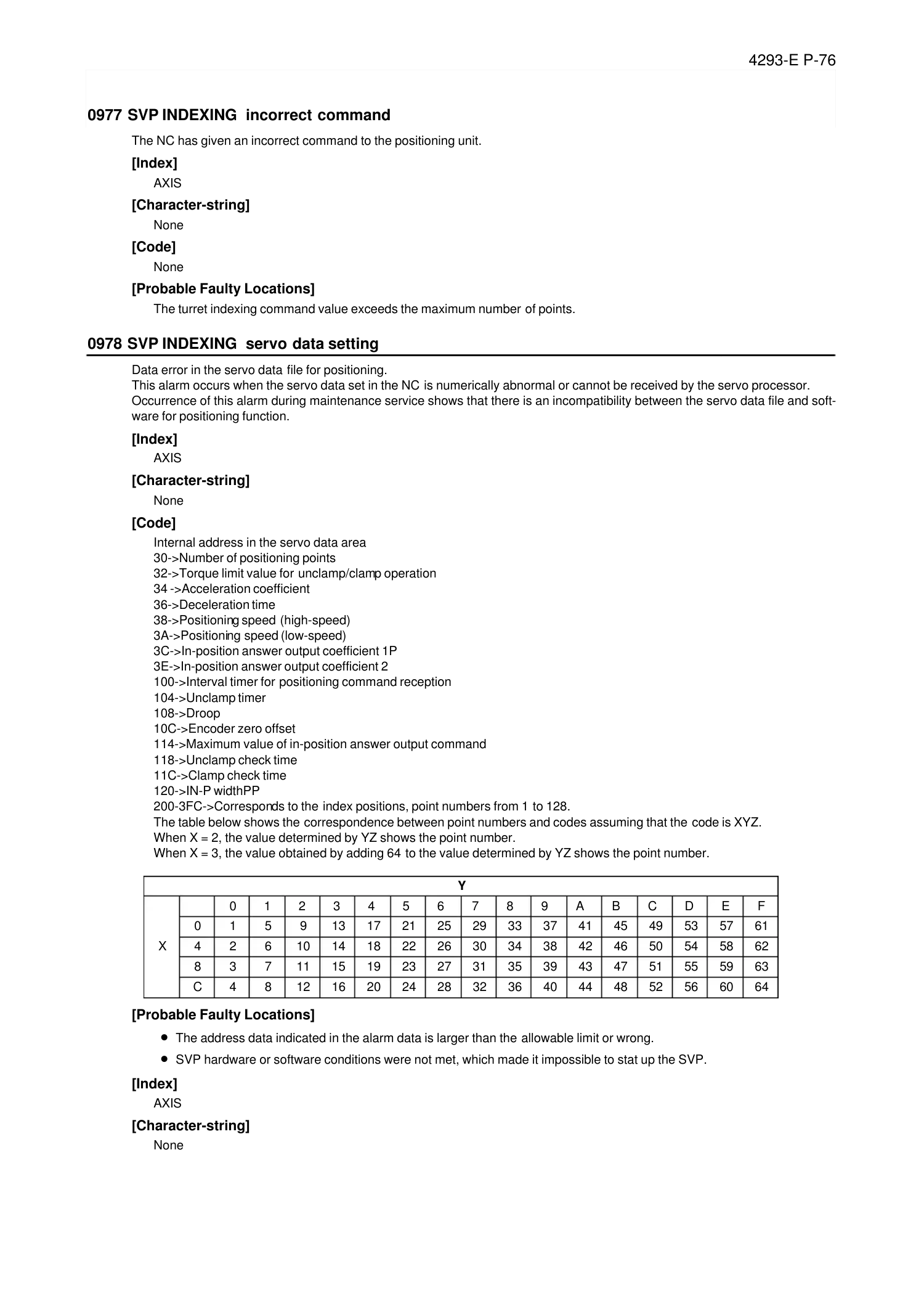
4293-E P-76
SECTION 3 ALARM P
0977 SVP INDEXING incorrect command
Eeoemale2148
The NC has given an incorrect command to the positioning unit.
[Index]
AXIS
[Character-string]
None
[Code]
None
[Probable Faulty Locations]
The turret indexing command value exceeds the maximum number of points.
0978 SVP INDEXING servo data setting
Eeoemale2149
Data error in the servo data file for positioning.
This alarm occurs when the servo data set in the NC is numerically abnormal or cannot be received by the servo processor.
Occurrence of this alarm during maintenance service shows that there is an incompatibility between the servo data file and soft-
ware for positioning function.
[Index]
AXIS
[Character-string]
None
[Code]
Internal address in the servo data area
30->Number of positioning points
32->Torque limit value for unclamp/clamp operation
34 ->Acceleration coefficient
36->Deceleration time
38->Positioning speed (high-speed)
3A->Positioning speed (low-speed)
3C->In-position answer output coefficient 1P
3E->In-position answer output coefficient 2
100->Interval timer for positioning command reception
104->Unclamp timer
108->Droop
10C->Encoder zero offset
114->Maximum value of in-position answer output command
118->Unclamp check time
11C->Clamp check time
120->IN-P widthPP
200-3FC->Corresponds to the index positions, point numbers from 1 to 128.
The table below shows the correspondence between point numbers and codes assuming that the code is XYZ.
When X = 2, the value determined by YZ shows the point number.
When X = 3, the value obtained by adding 64 to the value determined by YZ shows the point number.
[Probable Faulty Locations]
• The address data indicated in the alarm data is larger than the allowable limit or wrong.
• SVP hardware or software conditions were not met, which made it impossible to stat up the SVP.
[Index]
AXIS
[Character-string]
None
Y
X
0 1 2 3 4 5 6 7 8 9 A B C D E F
0 1 5 9 13 17 21 25 29 33 37 41 45 49 53 57 61
4 2 6 10 14 18 22 26 30 34 38 42 46 50 54 58 62
8 3 7 11 15 19 23 27 31 35 39 43 47 51 55 59 63
C 4 8 12 16 20 24 28 32 36 40 44 48 52 56 60 64
Page 84
4293-E P-77
SECTION 3 ALARM P
[Code]
XYYZZZZ
X = 1->Hardware conditions are not met.
YY= 1->The SVP board is not mounted.
ZZZZ = 0000
YY= 2->The SVP is in abnormal status.
ZZZZ ->SVP status
YY= 3->Abnormality has occurred in the system bus related to the SVP hardware.
ZZZZ ->System bus status
X = 2->SVP data conditions are not met.
YY= 1->Synchronous signal number is wrongly selected.
ZZZZ ->Selected synchronous signal number
YY= 2->Synchronous shift time is wrongly designated.
ZZZZ->Designated synchronous shift time
X = 3->Software conditions are not met.
YY= 1->SVP software is not installed.
ZZZZ = 0000
YY= 2->Servo parameters are not installed.
ZZZZ = 0000
[Probable Faulty Locations]
• SVP hardware of the problem axis
• Control software such as that for NC
0981 SVP LE sum check error
Eeoemale2150
A sum check error occurred in the communication data sent from LE (linear encoder).
[Index]
AXIS
[Character-string]
None
[Probable Faulty Locations]
• Contact failure or disconnection in LE transmission cable
• Faulty PCB in LE slider
[Measures to Take]
• Check the cables and connectors, and repair or replace them if defective.
• Change the slider.
0982 SVP LE data error
Eeoemale2151
The linear encoder generated an alarm. This alarm mainly indicates the abnormal amplitude of internal signal waveform.
[Index]
AXIS
[Character-string]
None
[Probable Faulty Locations]
Damaged PCB or LED in the slider
[Measures to Take]
Change the slider.
0983 SVP LE incre. abso. error
Eeoemale2152
The 80 MUm-division incremental APA data does not match the 2 mm & 80 MUm-division absolute APA data.
[Index]
AXIS
[Character-string]
None
Page 85
4293-E P-78
SECTION 3 ALARM P
[Probable Faulty Locations]
• Faulty PCB in the slider
• Soiled main scale, low air supply pressure to the main scale unit, defective or broken air piping, clogged air filter, or con-
taminated air
• Condensation in the main scale unit
[Measures to Take]
• Change the slider.
• Check the air supply pressure and piping connections. Change the air filter. Wipe the main scale glass surface.
• After checking the air supply pressure, wait for about three minutes before resupplying the power.
0984 SVP LE comparator AD error
Eeoemale2153
The 80 MUm-division comparator output does not match the A/D converter value.
[Index]
AXIS
[Character-string]
None
[Probable Faulty Locations]
• Faulty PCB in the slider
• Soiled main scale, low air supply pressure to the main scale unit, broken air piping, clogged air filter, or contaminated air
• Condensation in the main scale unit
[Measures to Take]
• Change the slider.
• Check the air supply pressure and piping connections. Change the air filter. Wipe the main scale glass surface.
• After checking the air supply pressure, wait for about three minutes before resupplying the power.
0985 SVP LE face rotation error
Eeoemale2154
The slider made an in-plane rotation and exceeded the allowable limit for scale matching.
[Index]
AXIS
[Character-string]
None
[Probable Faulty Locations]
Large pitching of the LE-mounted table caused the LE to exceed the scale matching limit. Or, the LE is mounted with devia-
tion in the pitching direction.
[Measures to Take]
Check the table pitching amount and LE slider mounted condition.
0986 SVP LE initial transfer data error
Eeoemale2155
An error occurred in the data initially transferred from LE with the power on.
[Index]
AXIS
[Character-string]
None
[Probable Faulty Locations]
• Faulty LE cable, disengaged connectors
• Contact failure in cable, loose connectors (Transmission failed during data transmission.)
• LE version does not agree with SVP control software.(Code:16)
Page 86
4293-E P-79
SECTION 3 ALARM P
0987 SVP LE application error
Eeoemale2156
The connected optical linear encoder is of an inapplicable type.
[Index]
AXIS
[Code]
XXXXXXXX
XXXXXXXX:->Connected optical linear encoder type
0989 CPU information table data unsuitable
Eeoemale2157
The CPU information table contains a value exceeding the setting range.
[Index]
None
[Character-string]
None
[Code]
XXYYZZZZ
XX: Main processor number that detected the error
1->Main board No. 1
2->Main board No. 2
3->Main board No. 3
4->Main board No. 4
5->Main board No. 5
6->Main board No. 6
YY:
1->Application information No. 1 table
2->Application information No. 2 table
3->Application information No. 3 table
4->Application information No. 4 table
5->Application information No. 5 table
ZZZZ:->Table index value
0990 TASK generate error
Eeoemale2158
The NC failed to create a task.
[Index]
None
[Character-string]
’ABBBB’
A= 1 to 7 ... Main board number which detected this alarm
= B ........ The FCP board detected this alarm.
BBBB= Task name
[Code]
XXXXYYYY
XXXX:->ID of failed task
YYYY:
1->Task ID error (The objective task is already present.)
2->No TCB range (The number of tasks exceeded 16.)
0991 TASK information table data unsuitable
Eeoemale2159
The task information table number is 0.
[Index]
None
[Character-string]
None
[Code]
XXYYZZZZ
XX: Main processor number that detected the error
Page 87
4293-E P-80
SECTION 3 ALARM P
1->Main board No. 1
2->Main board No. 2
3->Main board No. 3
4->Main board No. 4
5->Main board No. 5
6->Main board No. 6
YY:
1->Application information No. 1 table
2->Application information No. 2 table
3->Application information No. 3 table
4->Application information No. 4 table
5->Application information No. 5 table
ZZZZ:->Table index value
0992 PLC backup data file read
Eeoemale2160
The PLC backup data or M code data file cannot be read from the memory.
[Index]
None
[Character-string]
None
20001:The M code data file is not found or a wrong file name is specified.
20002:The M code data file cannot be opened.
[Code]
None->M code data file error
1->The PLC backup file is not found or a wrong file name is specified.
2->The PLC backup file cannot be opened.
[Probable Faulty Locations]
• If the alarm occurred during normal NC operation, the file has been deleted or its data has been destroyed.
• If the alarm occurred without NC operation after installation of control software, the file type was wrong or no such file
was stored in the memory.
[Measures to Take]
• In the case of the above 1), reinstall the control software.
• In the case of the above 2), check the control floppy disk data (such as file name) and recreate the floppy disk.
[Related Specifications]
PLC specification
0993 TCP/IP board error
Eeoemale2161
An error occurred on TCP/IP board.
[Index]
None
[Character-string]
None
[Code]
=1...Initialization of TCP/IP board is not completed.
=2...Preparation for system operation of TCP/IP board is not completed.
0994 TCP/IP configuration file error
Eeoemale2162
The TCP/IP configuration file includes an error.
[Index]
None
[Character-string]
None
[Code]
=1: Configuration file (MD0: ADAPTCNTRL.SY3) not found
=2: Configuration file attribute error
Page 88
4293-E P-81
SECTION 3 ALARM P
=3: Configuration file opening error
=4: Wrong IP address specified at destination station
=5: Wrong port number specified at destination station
=6: Wrong port number specified at sending station
=7: Logging ON/OFF setting error
=8: Wrong IP address specified at sending station
=9: Network mask designation error
=10: Broadcast address designation error
=B: Use or nonuse of the running file name is wrongly specified.
The following are the error codes used for TCP/IP driver.
=C: Sector device designation error
=D: Sector device not set
=E: Descriptor error
=F: Parameter setting error
=2E: Specified configuration file not found
=2F: Configuration file opening error
=30: Configuration file closing error
=31: Configuration file reading error
=32: No data in configuration file
=33: IP address error
=34: No IP address
0995 Machine axis data file
Eeoemale2163
The axis control constant data does not match the actual machine axes (such as magazine axis).
[Index]
None
[Character-string]
Machine axis name
[Code]
1->An axis name in the data downloaded from the machine axis data file does not correspond to the name of axis actually
mounted.
[Probable Faulty Locations]
• Defective creation of the machine axis data file
• Data input error in creation of the control software
0996 PLC axis data file
Eeoemale2164
The PLC axis control constants do not match the machine specifications.
[Index]
None
[Character-string]
PLC axis name
[Code]
1->The axis names downloaded from PLC axis data file do not match the actually mounted axis names.
2->The file type is not "PBU1".
3->The file has too large DB.
4->The specification data in the PLC axis data f ile is different from that in the SVP data file.
5: Memory location table of the axis backup data of the PLC axis data file is not found.
6: Memory location table of the axis parameters of the PLC axis data file is not found.
7: An error occurred when opening the PLC axis data file. File is short. File name or device name is incorrect.
8: Although the axis name in the PLC axis data file is the Okuma specification name, it differs from the registered name.
9: PLC axis data file is too small.
15:For OSP7030 / OSP730, the number of PLC axes exceeds 8.
16:For OSP7030 / OSP730, a PLC axis number exceeds 8.
17:For OSP7030 / OSP730, the rotary axis gear transmission ratio of the master axis is 0 although the axis changeover spec-
ification (function generation specification B bit 0) is set.
18:For OSP7030 / OSP730, the rotary axis gear transmission ratio of the slave axis is 0 although the axis changeover speci-
fication (function generation specification B bit 0) is set.
19:For OSP7030 / OSP730, pitch data of the master axis is 0 although the axis changeover specification (function generation
specification B bit 0) is set.
Page 89
4293-E P-82
SECTION 3 ALARM P
1A:For OSP7030 / OSP730, pitch data of the slave axis is 0 although the axis changeover specification (function generation
specification B bit 0) is set.
1B:For OSP7030 / OSP730, the rotary axis specification (servo data file) is not set although the point positioning specifica-
tion(function generation specification B bit 6) is set.
1C:For OSP7030 / OSP730, the linear axis specification (servo data file) is not set although the arbitrary positioning specifi-
cation (function generation specification B bit 7) is set.
1D:For OSP7030 / OSP730, the master axis of the axes with an independent position sensor is not found, or the master axis
is not set.
1E:For OSP7030 / OSP730, multiple axes are specified as the master axis of the axes with an independent position sensor.
1F:For OSP7030 / OSP730, detected speed of the axis with an independent position sensor is 0. This data is set by MCS
when the power is turned on.
20:For OSP7030 / OSP730, the rotary axis gear transmission ratio (EQDGT) or the convert factor (ESRDGT) of the axis with
an independent position sensor is not set. (setting value: 0)
[Probable Faulty Locations]
• Error in creation of PLC axis data file
• 21...Power is shut off during axis changeover control.
0997 PLC monitor backup data file read
Eeoemale2165
The backup data for PLC monitor cannot be read from the memory.
[Index]
None
[Character-string]
None
[Code]
1->The file is not found or its name is wrong.
2->The file cannot be opened.
3->The file cannot be read (no file data or any other reason).
4->A file other than backup file was specified.
5->The file cannot be closed.
6->Smaller file size
7->Larger file size
[Probable Faulty Locations]
• If the alarm occurred during normal NC operation, the backup data file has been deleted or its data has been destroyed.
• If the alarm occurred without NC operation after installation of control software, the file type was wrong or no such file
was stored in the memory.
[Measures to Take]
• In the case of the above 1), reinstall the control software.
•
In the case of the above 2), check the control floppy disk data (such as file name) and recreate the floppy disk.
[Related Specifications]
PLC specification
0998 PLC sequence program load
Eeoemale2166
Loading the PLC sequence program file failed.
[Index]
None
[Character-string]
None
[Code]
XXXX
1->The file ended before the NC loads any character.
3->The file ended while it is being loaded.
9->Device name is wrongly specified.
A->File name is wrongly specified.
B->The program file is not found.
100->PLC machine type is wrong.
200->PLC class is different.
300->file version is wrong.
Page 90
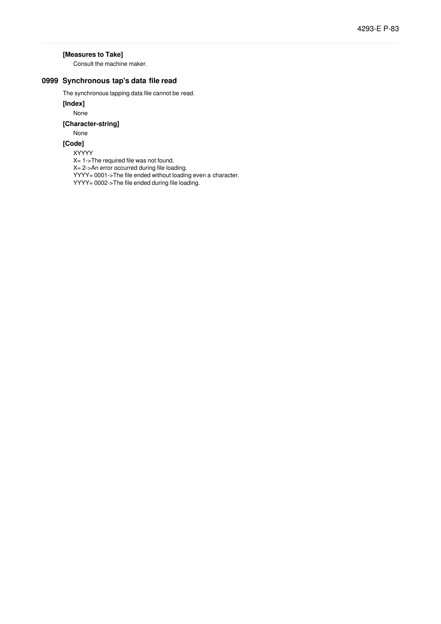
4293-E P-83
SECTION 3 ALARM P
[Measures to Take]
Consult the machine maker.
0999 Synchronous tap's data file read
Eeoemale2167
The synchronous tapping data file cannot be read.
[Index]
None
[Character-string]
None
[Code]
XYYYY
X= 1->The required file was not found.
X= 2->An error occurred during file loading.
YYYY= 0001->The file ended without loading even a character.
YYYY= 0002->The file ended during file loading.
Page 91
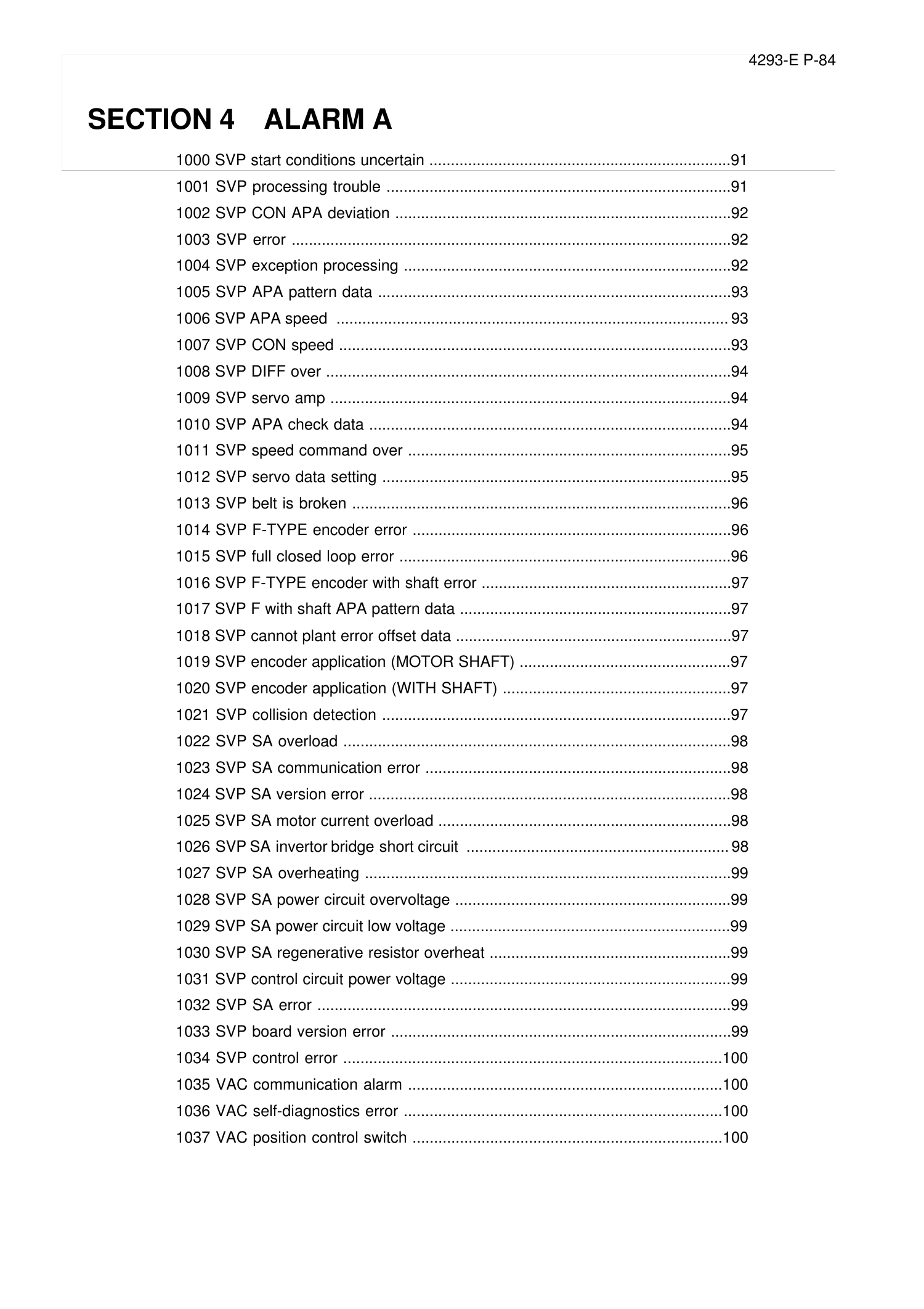
4293-E P-84
SECTION 4 ALARM A
SECTION 4 ALARM A
1000 SVP start conditions uncertain ......................................................................91
1001 SVP processing trouble ................................................................................91
1002 SVP CON APA deviation ..............................................................................92
1003 SVP error ......................................................................................................92
1004 SVP exception processing ............................................................................92
1005 SVP APA pattern data ..................................................................................93
1006 SVP APA speed ........................................................................................... 93
1007 SVP CON speed ...........................................................................................93
1008 SVP DIFF over ..............................................................................................94
1009 SVP servo amp .............................................................................................94
1010 SVP APA check data ....................................................................................94
1011 SVP speed command over ...........................................................................95
1012 SVP servo data setting .................................................................................95
1013 SVP belt is broken ........................................................................................96
1014 SVP F-TYPE encoder error ..........................................................................96
1015 SVP full closed loop error .............................................................................96
1016 SVP F-TYPE encoder with shaft error ..........................................................97
1017 SVP F with shaft APA pattern data ...............................................................97
1018 SVP cannot plant error offset data ................................................................97
1019 SVP encoder application (MOTOR SHAFT) .................................................97
1020 SVP encoder application (WITH SHAFT) .....................................................97
1021 SVP collision detection .................................................................................97
1022 SVP SA overload ..........................................................................................98
1023 SVP SA communication error .......................................................................98
1024 SVP SA version error ....................................................................................98
1025 SVP SA motor current overload ....................................................................98
1026 SVP SA invertor bridge short circuit .............................................................98
1027 SVP SA overheating .....................................................................................99
1028 SVP SA power circuit overvoltage ................................................................99
1029 SVP SA power circuit low voltage .................................................................99
1030 SVP SA regenerative resistor overheat ........................................................99
1031 SVP control circuit power voltage .................................................................99
1032 SVP SA error ................................................................................................99
1033 SVP board version error ...............................................................................99
1034 SVP control error ........................................................................................100
1035 VAC communication alarm .........................................................................100
1036 VAC self-diagnostics error ..........................................................................100
1037 VAC position control switch ........................................................................100
Page 92
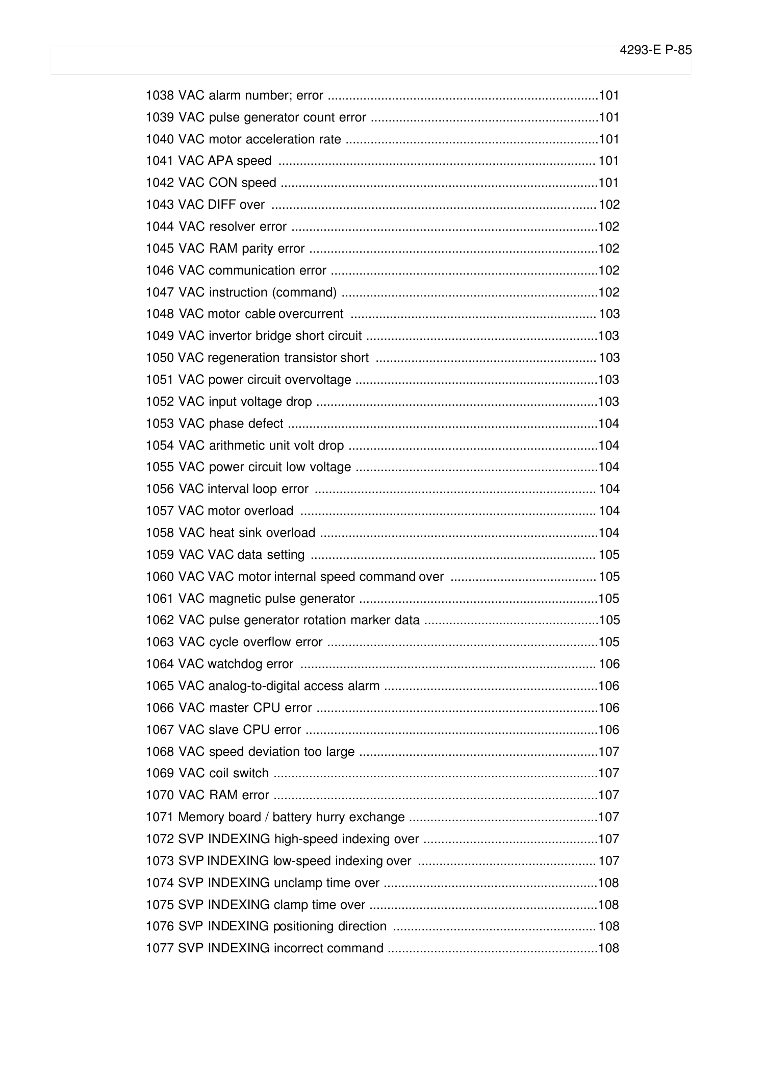
4293-E P-85
SECTION 4 ALARM A
1038 VAC alarm number; error ............................................................................101
1039 VAC pulse generator count error ................................................................101
1040 VAC motor acceleration rate .......................................................................101
1041 VAC APA speed ......................................................................................... 101
1042 VAC CON speed .........................................................................................101
1043 VAC DIFF over ........................................................................................... 102
1044 VAC resolver error ......................................................................................102
1045 VAC RAM parity error .................................................................................102
1046 VAC communication error ...........................................................................102
1047 VAC instruction (command) ........................................................................102
1048 VAC motor cable overcurrent ..................................................................... 103
1049 VAC invertor bridge short circuit .................................................................103
1050 VAC regeneration transistor short .............................................................. 103
1051 VAC power circuit overvoltage ....................................................................103
1052 VAC input voltage drop ...............................................................................103
1053 VAC phase defect .......................................................................................104
1054 VAC arithmetic unit volt drop ......................................................................104
1055 VAC power circuit low voltage ....................................................................104
1056 VAC interval loop error ............................................................................... 104
1057 VAC motor overload ................................................................................... 104
1058 VAC heat sink overload ..............................................................................104
1059 VAC VAC data setting ................................................................................ 105
1060 VAC VAC motor internal speed command over .........................................105
1061 VAC magnetic pulse generator ...................................................................105
1062 VAC pulse generator rotation marker data .................................................105
1063 VAC cycle overflow error ............................................................................105
1064 VAC watchdog error ................................................................................... 106
1065 VAC analog-to-digital access alarm ............................................................106
1066 VAC master CPU error ...............................................................................106
1067 VAC slave CPU error ..................................................................................106
1068 VAC speed deviation too large ...................................................................107
1069 VAC coil switch ...........................................................................................107
1070 VAC RAM error ...........................................................................................107
1071 Memory board / battery hurry exchange .....................................................107
1072 SVP INDEXING high-speed indexing over .................................................107
1073 SVP INDEXING low-speed indexing over .................................................. 107
1074 SVP INDEXING unclamp time over ............................................................108
1075 SVP INDEXING clamp time over ................................................................108
1076 SVP INDEXING positioning direction ......................................................... 108
1077 SVP INDEXING incorrect command ...........................................................108
Page 93
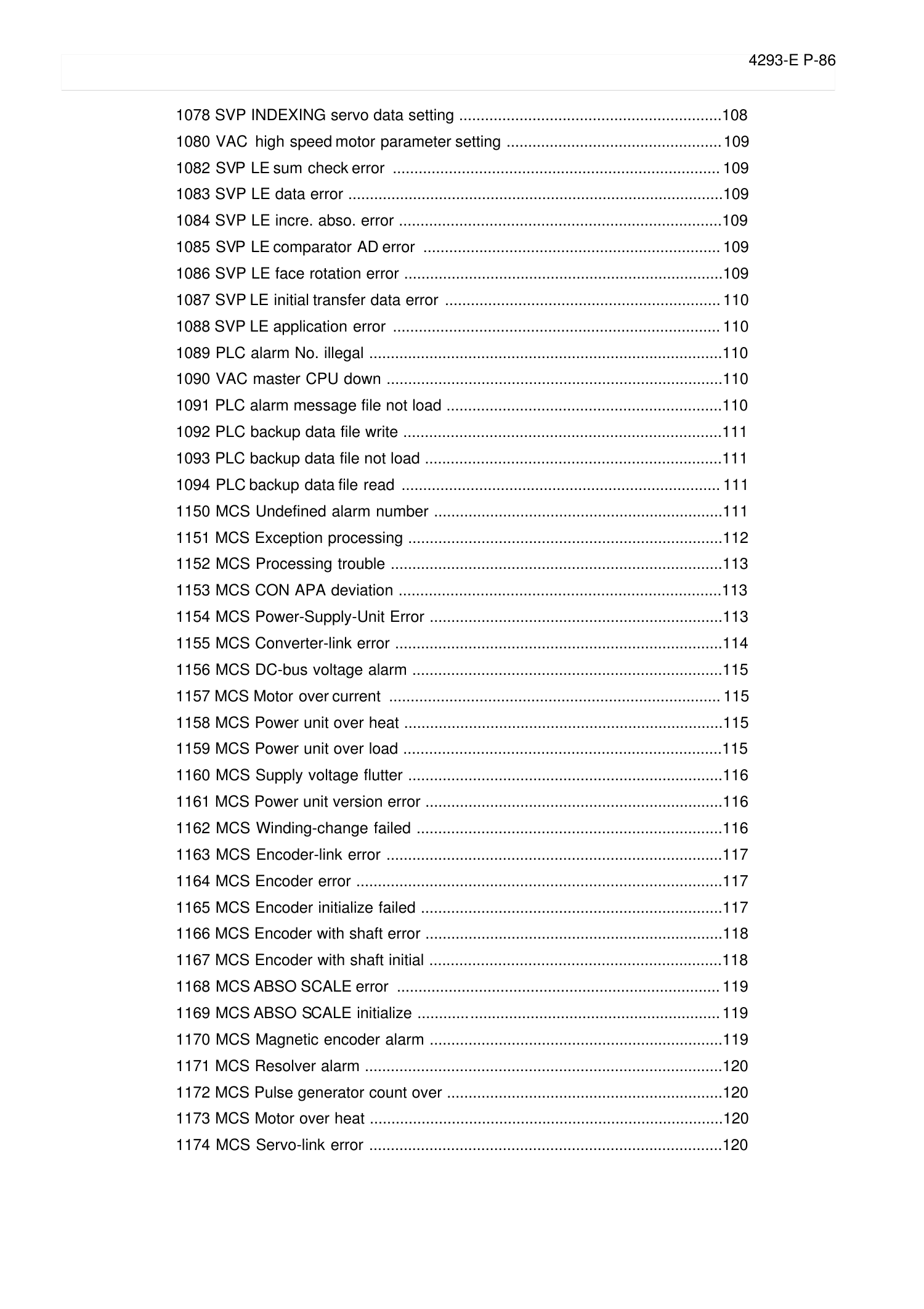
4293-E P-86
SECTION 4 ALARM A
1078 SVP INDEXING servo data setting .............................................................108
1080 VAC high speed motor parameter setting ..................................................109
1082 SVP LE sum check error ............................................................................ 109
1083 SVP LE data error .......................................................................................109
1084 SVP LE incre. abso. error ...........................................................................109
1085 SVP LE comparator AD error ..................................................................... 109
1086 SVP LE face rotation error ..........................................................................109
1087 SVP LE initial transfer data error ................................................................ 110
1088 SVP LE application error ............................................................................ 110
1089 PLC alarm No. illegal ..................................................................................110
1090 VAC master CPU down ..............................................................................110
1091 PLC alarm message file not load ................................................................110
1092 PLC backup data file write ..........................................................................111
1093 PLC backup data file not load .....................................................................111
1094 PLC backup data file read .......................................................................... 111
1150 MCS Undefined alarm number ...................................................................111
1151 MCS Exception processing .........................................................................112
1152 MCS Processing trouble .............................................................................113
1153 MCS CON APA deviation ...........................................................................113
1154 MCS Power-Supply-Unit Error ....................................................................113
1155 MCS Converter-link error ............................................................................114
1156 MCS DC-bus voltage alarm ........................................................................115
1157 MCS Motor over current ............................................................................. 115
1158 MCS Power unit over heat ..........................................................................115
1159 MCS Power unit over load ..........................................................................115
1160 MCS Supply voltage flutter .........................................................................116
1161 MCS Power unit version error .....................................................................116
1162 MCS Winding-change failed .......................................................................116
1163 MCS Encoder-link error ..............................................................................117
1164 MCS Encoder error .....................................................................................117
1165 MCS Encoder initialize failed ......................................................................117
1166 MCS Encoder with shaft error .....................................................................118
1167 MCS Encoder with shaft initial ....................................................................118
1168 MCS ABSO SCALE error ...........................................................................119
1169 MCS ABSO SCALE initialize ...................................................................... 119
1170 MCS Magnetic encoder alarm ....................................................................119
1171 MCS Resolver alarm ...................................................................................120
1172 MCS Pulse generator count over ................................................................120
1173 MCS Motor over heat ..................................................................................120
1174 MCS Servo-link error ..................................................................................120
Page 94
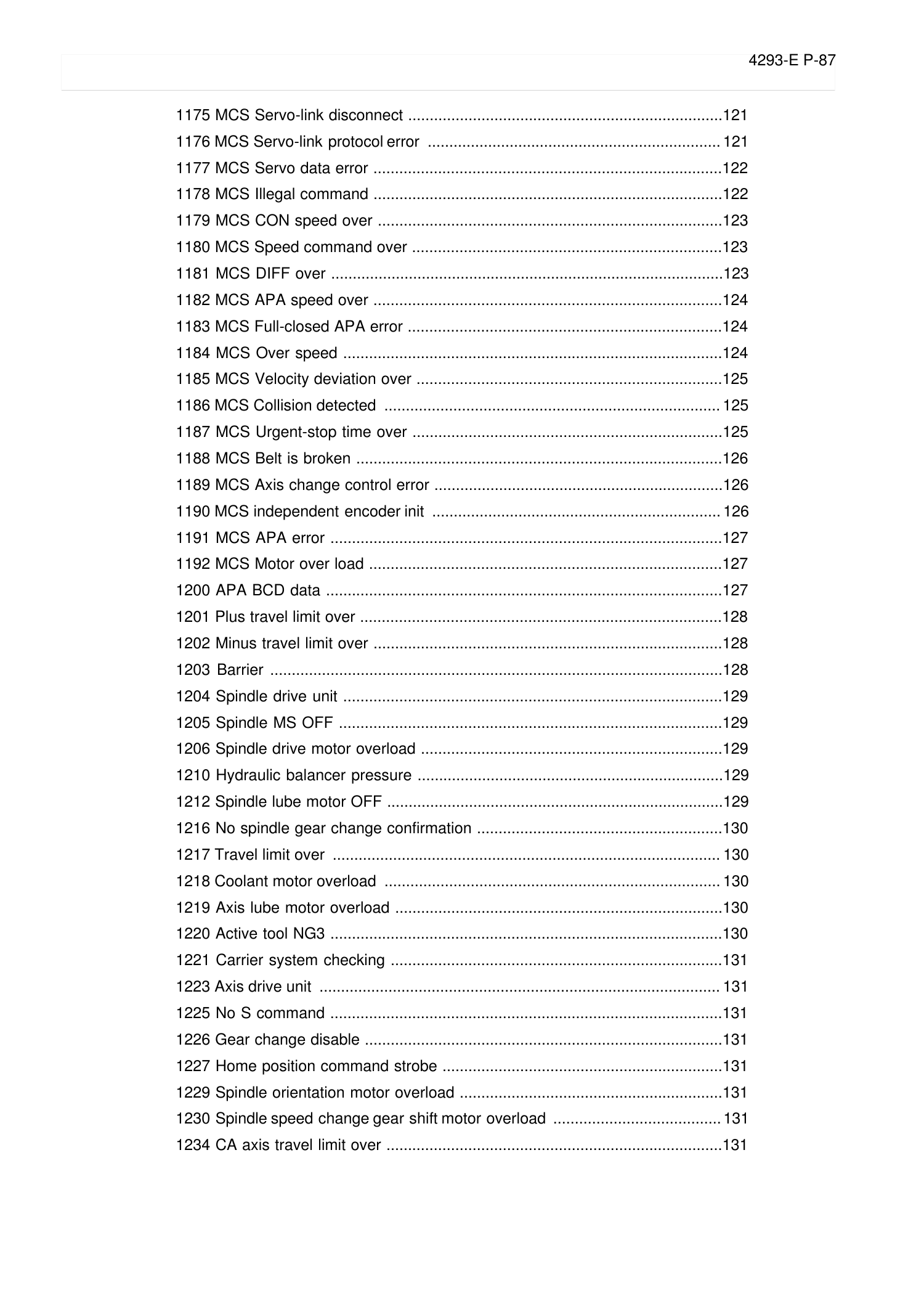
4293-E P-87
SECTION 4 ALARM A
1175 MCS Servo-link disconnect .........................................................................121
1176 MCS Servo-link protocol error .................................................................... 121
1177 MCS Servo data error .................................................................................122
1178 MCS Illegal command .................................................................................122
1179 MCS CON speed over ................................................................................123
1180 MCS Speed command over ........................................................................123
1181 MCS DIFF over ...........................................................................................123
1182 MCS APA speed over .................................................................................124
1183 MCS Full-closed APA error .........................................................................124
1184 MCS Over speed ........................................................................................124
1185 MCS Velocity deviation over .......................................................................125
1186 MCS Collision detected ..............................................................................125
1187 MCS Urgent-stop time over ........................................................................125
1188 MCS Belt is broken .....................................................................................126
1189 MCS Axis change control error ...................................................................126
1190 MCS independent encoder init ................................................................... 126
1191 MCS APA error ...........................................................................................127
1192 MCS Motor over load ..................................................................................127
1200 APA BCD data ............................................................................................127
1201 Plus travel limit over ....................................................................................128
1202 Minus travel limit over .................................................................................128
1203 Barrier .........................................................................................................128
1204 Spindle drive unit ........................................................................................129
1205 Spindle MS OFF .........................................................................................129
1206 Spindle drive motor overload ......................................................................129
1210 Hydraulic balancer pressure .......................................................................129
1212 Spindle lube motor OFF ..............................................................................129
1216 No spindle gear change confirmation .........................................................130
1217 Travel limit over .......................................................................................... 130
1218 Coolant motor overload .............................................................................. 130
1219 Axis lube motor overload ............................................................................130
1220 Active tool NG3 ...........................................................................................130
1221 Carrier system checking .............................................................................131
1223 Axis drive unit ............................................................................................. 131
1225 No S command ...........................................................................................131
1226 Gear change disable ...................................................................................131
1227 Home position command strobe .................................................................131
1229 Spindle orientation motor overload .............................................................131
1230 Spindle speed change gear shift motor overload ....................................... 131
1234 CA axis travel limit over ..............................................................................131
Page 95
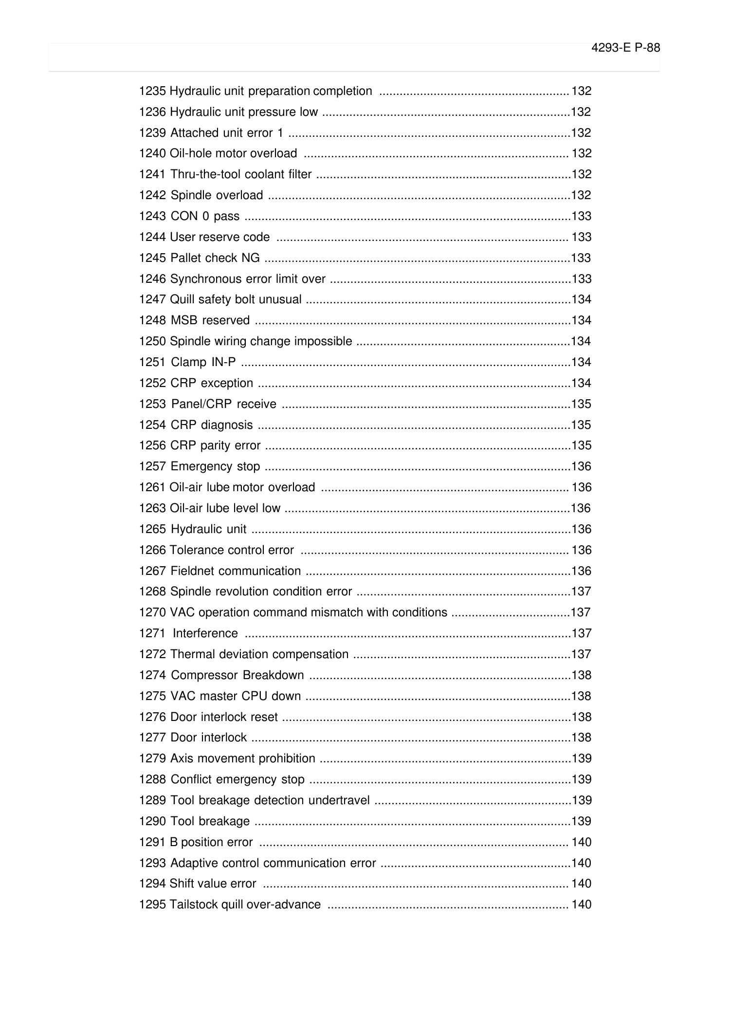
4293-E P-88
SECTION 4 ALARM A
1235 Hydraulic unit preparation completion ........................................................ 132
1236 Hydraulic unit pressure low .........................................................................132
1239 Attached unit error 1 ...................................................................................132
1240 Oil-hole motor overload .............................................................................. 132
1241 Thru-the-tool coolant filter ...........................................................................132
1242 Spindle overload .........................................................................................132
1243 CON 0 pass ................................................................................................133
1244 User reserve code ...................................................................................... 133
1245 Pallet check NG ..........................................................................................133
1246 Synchronous error limit over .......................................................................133
1247 Quill safety bolt unusual ..............................................................................134
1248 MSB reserved .............................................................................................134
1250 Spindle wiring change impossible ...............................................................134
1251 Clamp IN-P .................................................................................................134
1252 CRP exception ............................................................................................134
1253 Panel/CRP receive .....................................................................................135
1254 CRP diagnosis ............................................................................................135
1256 CRP parity error ..........................................................................................135
1257 Emergency stop ..........................................................................................136
1261 Oil-air lube motor overload ......................................................................... 136
1263 Oil-air lube level low ....................................................................................136
1265 Hydraulic unit ..............................................................................................136
1266 Tolerance control error ............................................................................... 136
1267 Fieldnet communication ..............................................................................136
1268 Spindle revolution condition error ...............................................................137
1270 VAC operation command mismatch with conditions ...................................137
1271 Interference ................................................................................................137
1272 Thermal deviation compensation ................................................................137
1274 Compressor Breakdown .............................................................................138
1275 VAC master CPU down ..............................................................................138
1276 Door interlock reset .....................................................................................138
1277 Door interlock ..............................................................................................138
1279 Axis movement prohibition ..........................................................................139
1288 Conflict emergency stop .............................................................................139
1289 Tool breakage detection undertravel ..........................................................139
1290 Tool breakage .............................................................................................139
1291 B position error ........................................................................................... 140
1293 Adaptive control communication error ........................................................140
1294 Shift value error .......................................................................................... 140
1295 Tailstock quill over-advance ....................................................................... 140
Page 96
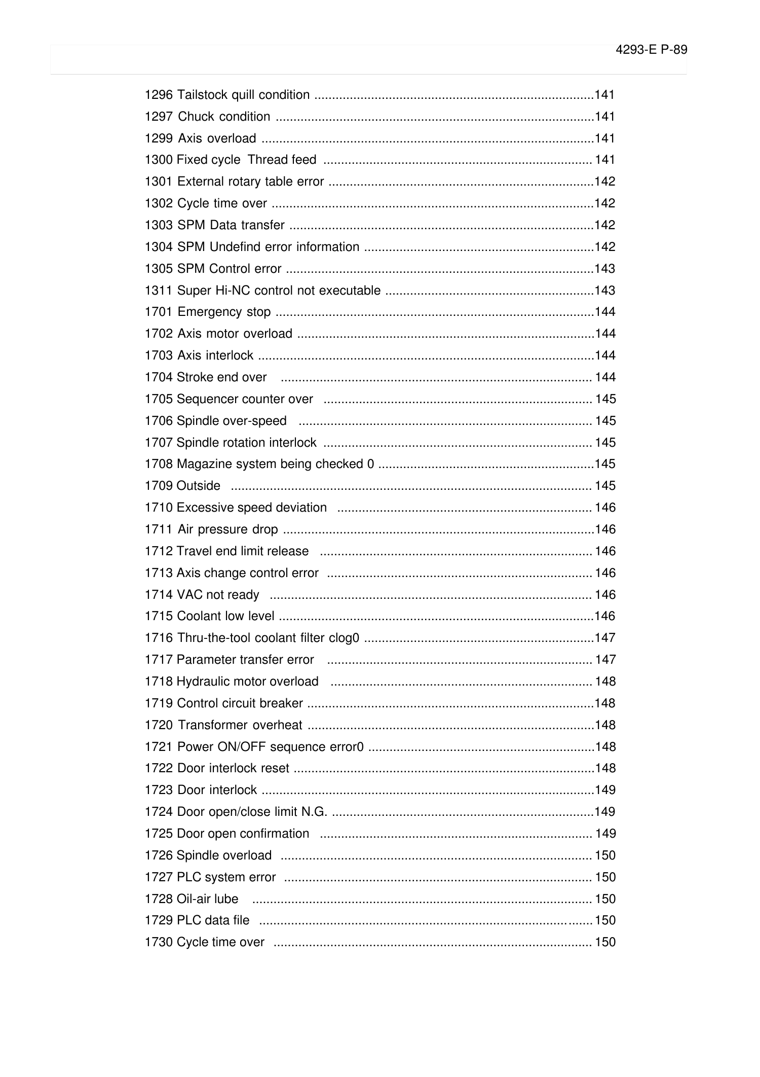
4293-E P-89
SECTION 4 ALARM A
1296 Tailstock quill condition ...............................................................................141
1297 Chuck condition ..........................................................................................141
1299 Axis overload ..............................................................................................141
1300 Fixed cycle Thread feed ............................................................................ 141
1301 External rotary table error ...........................................................................142
1302 Cycle time over ...........................................................................................142
1303 SPM Data transfer ......................................................................................142
1304 SPM Undefind error information .................................................................142
1305 SPM Control error .......................................................................................143
1311 Super Hi-NC control not executable ...........................................................143
1701 Emergency stop ..........................................................................................144
1702 Axis motor overload ....................................................................................144
1703 Axis interlock ...............................................................................................144
1704 Stroke end over ........................................................................................ 144
1705 Sequencer counter over ............................................................................ 145
1706 Spindle over-speed ................................................................................... 145
1707 Spindle rotation interlock ............................................................................ 145
1708 Magazine system being checked 0 .............................................................145
1709 Outside ...................................................................................................... 145
1710 Excessive speed deviation ........................................................................ 146
1711 Air pressure drop ........................................................................................146
1712 Travel end limit release ............................................................................. 146
1713 Axis change control error ........................................................................... 146
1714 VAC not ready ........................................................................................... 146
1715 Coolant low level .........................................................................................146
1716 Thru-the-tool coolant filter clog0 .................................................................147
1717 Parameter transfer error ........................................................................... 147
1718 Hydraulic motor overload .......................................................................... 148
1719 Control circuit breaker .................................................................................148
1720 Transformer overheat .................................................................................148
1721 Power ON/OFF sequence error0 ................................................................148
1722 Door interlock reset .....................................................................................148
1723 Door interlock ..............................................................................................149
1724 Door open/close limit N.G. ..........................................................................149
1725 Door open confirmation ............................................................................. 149
1726 Spindle overload ........................................................................................ 150
1727 PLC system error ....................................................................................... 150
1728 Oil-air lube ................................................................................................ 150
1729 PLC data file ..............................................................................................150
1730 Cycle time over .......................................................................................... 150
Page 97
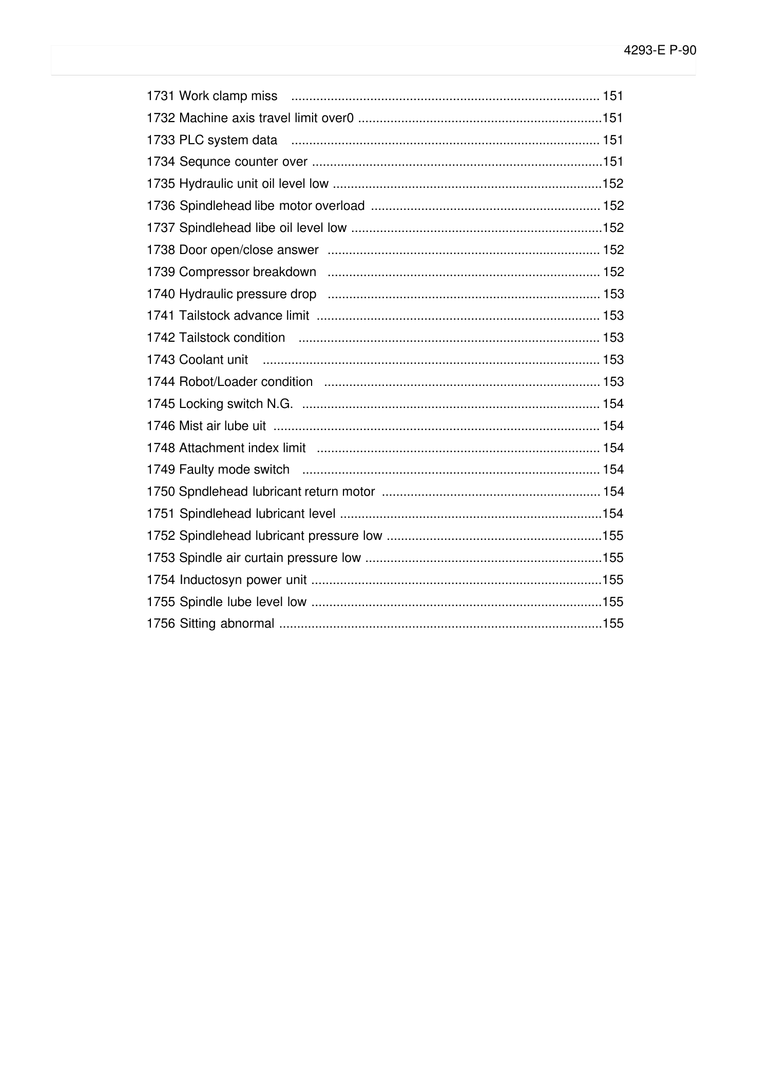
4293-E P-90
SECTION 4 ALARM A
1731 Work clamp miss ...................................................................................... 151
1732 Machine axis travel limit over0 ....................................................................151
1733 PLC system data ...................................................................................... 151
1734 Sequnce counter over .................................................................................151
1735 Hydraulic unit oil level low ...........................................................................152
1736 Spindlehead libe motor overload ................................................................ 152
1737 Spindlehead libe oil level low ......................................................................152
1738 Door open/close answer ............................................................................ 152
1739 Compressor breakdown ............................................................................ 152
1740 Hydraulic pressure drop ............................................................................ 153
1741 Tailstock advance limit ............................................................................... 153
1742 Tailstock condition .................................................................................... 153
1743 Coolant unit .............................................................................................. 153
1744 Robot/Loader condition ............................................................................. 153
1745 Locking switch N.G. ................................................................................... 154
1746 Mist air lube uit ........................................................................................... 154
1748 Attachment index limit ............................................................................... 154
1749 Faulty mode switch ................................................................................... 154
1750 Spndlehead lubricant return motor ............................................................. 154
1751 Spindlehead lubricant level .........................................................................154
1752 Spindlehead lubricant pressure low ............................................................155
1753 Spindle air curtain pressure low ..................................................................155
1754 Inductosyn power unit .................................................................................155
1755 Spindle lube level low .................................................................................155
1756 Sitting abnormal ..........................................................................................155
Page 98
4293-E P-91
SECTION 4 ALARM A
1000 SVP start conditions uncertain
Eeoemale3001
SVP hardware or software conditions were not met, which made it impossible to start up the SVP.
[Index]
AXIS
[Code]
XYYZZZZ
X=1->Hardware-related conditions are not met.
YY=1->The SVP board is not mounted.
ZZZZ=0000
YY=2->The SVP is in abnormal status.
ZZZZSVP status
YY=3->The system bus related to the SVP hardware is in abnormal status.
ZZZZ:System bus status
X=2->SVP data conditions are not met.
YY=1->Wrong synchronous signal number is selected.
ZZZZ:Selected synchronous signal number
YY=2->Synchronous shift time is wrongly designated.
ZZZZ:Designated synchronous shift time
X=3->Software-related conditions are not met.
YY=1->The SVP software is not installed.
ZZZZ=0000
YY=2->Servo parameters are not installed.
ZZZZ=0000
[Probable Faulty Locations]
• SVP hardware of the problem axis
• Control software such as that for NC
• NC specifications
1001 SVP processing trouble
Eeoemale3002
The SVP is in the trouble indicated by the following codes.
[Index]
AXIS
[Code]
XYYZZZZ
X=1->Internal error
The SVP has caused either parity loop error or protect error.
YY->Internal error status
ZZZZ:Two high-order bytes of the SVP system address in trouble
X=2->Time out
The SVP does not send any response within 20 seconds at the time of start up. Minute investigation should be made to
locate the cause.
Since the SVP cannot detect the start up signal, it cannot execute the start up sequence.
YY=00
ZZZZ=000000
X=3->Double bus error
During bus error exception processing by SVP, a bus error has occurred again. The SVP hardware will probably be defective.
YY:System bus status
ZZZZ=000000
X=4->SVP command execution
The SVP has obtained wrong diagnostic results of CPU command execution. The CPU will probably be defective.
YY:Diagnostic results
ZZZZ=000000
X=5->SVP trouble detected by the control software such as that for NC. Some trouble has occurred in the SVP.
[Probable Faulty Locations]
• SVP hardware of the problem axis
• SVP software of the problem axis
• Control software such as that for NC
Page 99
4293-E P-92
SECTION 4 ALARM A
1002 SVP CON APA deviation
Eeoemale3003
Deviation between CON and APA has exceeded the preset limit.
The deviation can be obtained by the formula: [Calculated value written in SVP]
- [Actual position read from SVP].
This value is monitored by the control software such as that for NC.
The SVP usually monitors DIFF. However, when the SVP becomes unable to monitor DIFF due to fatal abnormality, this monitor-
ing function will prevent the system overrun.
[Index]
AXIS
[Code]
Absolute deviation value in hexadecimal [reference unit]
[Probable Faulty Locations]
SVP of the problem axis
1003 SVP error
Eeoemale3004
The control software such as that for NC has detected a system alarm signal sent from the SVP hardware. For details, refer to the
specification for the mounted SVP version.
[Index]
AXIS
[Character-string]
None
[Code]
*??##&&
* --- Axis number of which SVP board’s CPU has caused the error (If 2, the problem SVP board is that for the 2nd axis.)
?? --- Board status in hexadecimal
bit7 bit6 bit5 bit4 bit3 bit2 bit1 bit0
RUN HALT CPUOFF 0 0 0 SNMI MSTP
## --- Bus error status in hexadecimal
bit7 bit6 bit5 bit4 bit3 bit2 bit1 bit0
SBER SBPAR CYCER 0 PROT DAI LOOP ECC
&& --- Always 00
[Probable Faulty Locations]
• Hardware defect of the SVP board indicated with the code *
• Software defect
1004 SVP exception processing
Eeoemale3005
Fatal abnormality has occurred in processing by SVP software.
[Index]
AXIS
[Character-string]
Detected error factor
# 1->Bus error
# 2->Address error
# 3->Illegal instruction error
# 4->Zero divide error
# 5->CHK instruction error
# 6->TRAPV instruction error
# 7->Privilege violation error
# 8->Trace error
# 9->Line 1010 emulator error
#10->Line 1111 emulator error
#11->Unused area error
#12->Coprocessor illegal protocol error
#13->Format error
#14->Uninitialized interrupt error
#15->Spurious interrupt error
#16->Interrupt error
#17->INT7 error
Page 100
4293-E P-93
SECTION 4 ALARM A
#18->Debugger interrupt alarm
#19->INT2 loop error
#20->INT5 loop error
#21->Speed command calculation delay alarm
#22->TRAP error
#23->Floating-point coprocessor error
#24->PMMU error
#25->User interrupt error
#26->Board version error
#27->Memory test error
[Code]
The CPU program counter value is displayed except when the following character-strings appear.
With #26, the SVP hardware ID number is displayed as a code.
With #27, the memory address at the time of abnormality detection is displayed as a code.
[Probable Faulty Locations]
• SVP board
• SVP software
1005 SVP APA pattern data
Eeoemale3006
The SVP has successively detected wrong patterns of positional data sent from the position encoder.
Ex. Displayed code: 8000
Conversion into the octal number
8000(hexadecimal number)->100000 (octal number) Since the E8 unit reads up to 5 digits and ignores the sixth digit, all the digits
become 0, causing the OSP to judge that no data is output from the encoder.
[Index]
AXIS
[Code]
Pattern of the read positional data(APA high-order digit)
[Probable Faulty Locations]
• Position encoder of the problem axis
• SVP hardware of the problem axis
• Timing signal from the NC unit
1006 SVP APA speed
Eeoemale3007
The position encoder value (RAPA) changes according to the motor speed. The NC checks the variation of position encoder val-
ues at regular intervals. If the feedrate of each axis is abnormally high compared with the normal rapid traverse rate, or the value
changes in abnormal manner due to malfunction of the position encoder, the variation per unit time exceeds a fixed allowable
limit, causing this alarm.
[Index]
AXIS
[Code]
Variation of the position encoder values in hexadecimal [encoder unit /3.2ms]
However, the following codes represents special meanings.
FFFFFFFF->The variation has exceeded the liner axis stroke.
FFFFFFFE->The variation has exceeded the rotary axis stroke (360-deg), or the positional data of the infinite axis has
changed to a negative value.
FFFFFFFD->The variation has exceeded the infinite axis stroke.
[Probable Faulty Locations]
• Position encoder of the problem axis or the cables connected with the encoder.
• Motor for driving the problem axis
• Drive unit of the problem axis
• SVP hardware of the problem axis
1007 SVP CON speed
Eeoemale3008
When the axis is in the target position or at a standstill, the target value, operation value, and actual position data are the same.
With designation of an axis moving command, the NC starts calculating the path to the target position, thus creating operation
 Loading...