

Page 1

CNC SYSTEM
OSP-E100
OSP-E10
MacMan
INSTRUCTION MANUAL
(6th Edition)
Pub No. 4345-E-R5 (SE34-008-R6) May 2002
Page 2

SAFETY PRECAUTIONS
4345-E P-(i)
SAFETY PRECAUTIONS
The NC unit that features the IGF function is equipped with a variety of safety devices to protect personnel and the machine from hazards arising as a result of unforeseen accidents while operating
the machine.
However, incorrect use of the function can lead to serious accidents and injuries. In order to prevent
such accidents, read this manual and related manuals carefully so that you can use the IGF function
correctly.
The points presented below are those that require particular attention when using the IGF function.
Be sure to read this information and follow the instructions in it. The cautions below and the warning
signs attached to the machine cover only those hazards which we can predict. Be aware that they
do not cover all possible hazards.
1. Precautions on Reading This Manual
This manual only provides information relating to the IGF function: in addition to this manual, manuals relating to the operation of the machine and NC unit, the parameters, alarms/errors, maintenance, etc., are also provided.
Read these manuals before actually using the IGF function or running an NC program created using
the IGF function.
2. Precautions on Use
Eeospkkpl001
Eeospkkpl002
2-1. Starting up the IGF Function
For details about turning on the power and selecting the operation mode before starting up the IGF
function, refer to the manuals relating to operation of the machine and NC unit. Strictly observe the
cautions given in these manuals.
2-2. Operations while Using the IGF Function
If any alarm or error occurs while using the IGF function, determine its exact nature and take corrective action by referring to this manual and the manuals relating to alarms and errors.
Eeospkkpl003
Eeospkkpl004
Page 3

SAFETY PRECAUTIONS
2-3. Running NC Programs Created Using the IGF Function
4345-E P-(ii)
(1) Use the simulation function of the IGF function to check the operation before running an NC
program created using the IGF function to perform actual machining.
(2) Never run a program created using the IGF function to perform actual machining without check-
ing its operation. Run the program with no workpiece and make sure that there is no interference, then cut a workpiece in the single block mode. If no problems are discovered, automatic
operation may be started.
(3) Confirm safety before performing operations involving spindle rotation or axis motion.
(4) Never touch the moving parts of the machine, chips, or the workpiece during machine opera-
tion.
(5) Check the tool offset values.
(6) Check the zero offset values.
(7) Make sure that all override settings on the machine operation panel are set to 100%. Or, if nec-
essary, use a lower override.
(8) If using a machine with a cover, always close the cover before starting operation. Do not oper-
ate the machine with any safety cover removed.
(9) Check carefully that the spindle speed, feedrates, infeeds, etc. specified in created programs
are within the permissible ranges for the tools, chuck, fixture, etc., used during operation.
3. On Finishing Work
(1) On finishing work, clean the vicinity of the machine.
(2) Return all devices to their predetermined retraction positions.
Eeospkkpl005
Eeospkkpl006
(3) Always turn off the power to the machine before leaving it.
(4) Always quit the IGF function before turning off the power.
(5) To turn off the power, turn off the CONTROL ON switch on the operation panel first, then the
main power disconnect switch.
4. When Performing Maintenance Inspections/When Trouble Occurs
(1) To execute an emergency stop, press the emergency stop button on the operation panel.
(2) Consult the person responsible for maintenance to determine what corrective measures need
to be taken.
(3) Before contacting the service center after an alarm or error has occurred, write down all the rel-
evant alarm and error messages displayed.
(4) Carefully read this manual and the manuals relating to alarms and errors, machine and NC unit
operation, and parameters, etc., before taking corrective action during a maintenance inspection or in response to trouble. Strictly observe the cautions given in these manuals.
Eeospkkpl007
Page 4
5. Symbols Used in Manual
4345-E P-(iii)
SAFETY PRECAUTIONS
The following warning indications are used in this manual to draw attention to information of particular importance. Read the instructions marked with these symbols carefully and follow them.
Eeospkkpl008
DANGER
Indicates an imminent hazard which, if not avoided, will result in death or serious injury.
WARNING
Indicates hazards which, if not avoided, could result in death or serious injury.
CAUTION
Indicates hazards which, if not avoided, could result in minor injuries or damage to devices or
equipment.
NOTICE
Indicates precautions relating to operation or use.
Page 5

INTRODUCTION
4345-E P-(i)
INTRODUCTION
Thank you very much for purchasing our numerical control unit.
Before using this NC unit (hereafter simply called NC), thoroughly read this manual in order to
ensure correct use.
This manual explains how to use and maintain the NC so that it will deliver its full performance and
maintain accuracy over a long term.
You must pay particular attention to the cautions given in this manual, read them carefully, and
make sure you fully understand them before operating the NC.
Display Screens
The NC display screens vary with the selected NC specifications.
The screens shown in this manual, therefore, may not exactly the
same with those displayed on your NC.
Eeospkkan001
Page 6

4345-E P-(i)
TABLE CONTENTS
TABLE CONTENTS
SECTION 1 MacMan......................................................................................................1
1. MacMan Provides the Live Productions Status Information ......................................................... 1
2. MacMan Slashes Down Time ....................................................................................................... 3
3. Screen Transition Diagram ........................................................................................................... 3
SECTION 2 MacMan MAIN SCREEN............................................................................4
1. Machining Status .......................................................................................................................... 5
2. Recent Machining Report ............................................................................................................. 6
3. Adjusting the Number of Work Count ........................................................................................... 7
4. Changing the Reason of Not-operating Status ............................................................................. 7
SECTION 3 REPORT INFORMATION DISPLAY........................................................11
SECTION 4 MACHINING REPORT DISPLAY.............................................................14
1. Daily Machining Report (Today) ................................................................................................. 14
2. Daily Machining Report (Pre Day) ..............................................................................................16
3. Period Machining Report ............................................................................................................ 17
4. Output to Floppy Disk ................................................................................................................. 18
SECTION 5 OPERATING REPORT ............................................................................19
1. Daily Operating Report (Today).................................................................................................. 19
2. Daily Operating Report (Pre Day)............................................................................................... 20
3. Period Operating Report ............................................................................................................ 21
SECTION 6 OPERATING HISTORY ...........................................................................23
1. Daily Operating History (Today) ................................................................................................. 23
2. Daily Operating History (Pre Day) .............................................................................................. 25
SECTION 7 TROUBLESHOOTING INFORMATION...................................................26
SECTION 8 ALARM HISTORY ....................................................................................27
1. Displaying the Alarm History....................................................................................................... 27
2. Changing Logged Alarm Levels..................................................................................................28
SECTION 9 OPERATION HISTORY ...........................................................................30
1. Operate Panel............................................................................................................................. 30
SECTION 10 PARAMETER SETTING .........................................................................33
1. REPORT DATA .......................................................................................................................... 34
Page 7

4345-E P-(ii)
TABLE CONTENTS
2. OUTPUT DATA .......................................................................................................................... 36
3. Initialization ................................................................................................................................. 39
Page 8
SECTION 1 MacMan
4345-E P-1
SECTION 1 MacMan
The MacMan has been developed by focusing on the following problems among a variety of problems to be solved:
• What should we do to improve operation efficiency of the machine tools and other production
equipment?
• What should we do to shorten lead time to output products?
Higher operation efficiency and shorter lead time are both the key themes to be achieved to successfully shift the production style to small lot production with a large number of workpiece kinds
and then to variable lot size production.
The MacMan will provide you the information necessary for finding solutions to these themes.
Eeospkku1001
1. MacMan Provides the Live Productions Status Information
If you want to run the production equipment more efficiently, the first step you must take is to "find"
the actual operating efficiency. Here, the term "find" does not mean "seeing", but it includes the processing to "digitize" the information. Similarly, to shorten the lead time, you must "find" the status
how the production progresses. To "find" the actual status is the first step to improvements.
The MacMan collects and outputs the continuously changing actual status of production.
• It outputs the actual status to the NC screen. Improvements at the production field by an opera-
tor is possible by viewing the actual status.
• It outputs the actual status to the MS-DOS format floppy disk. Production field management by
using a personal computer is possible.
Eeospkku1002
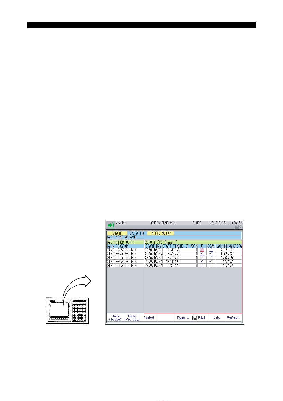
(1) Machining Report
Job progress status is displayed for each of the selected main programs.
EIOSPKKU1003R01
Page 9
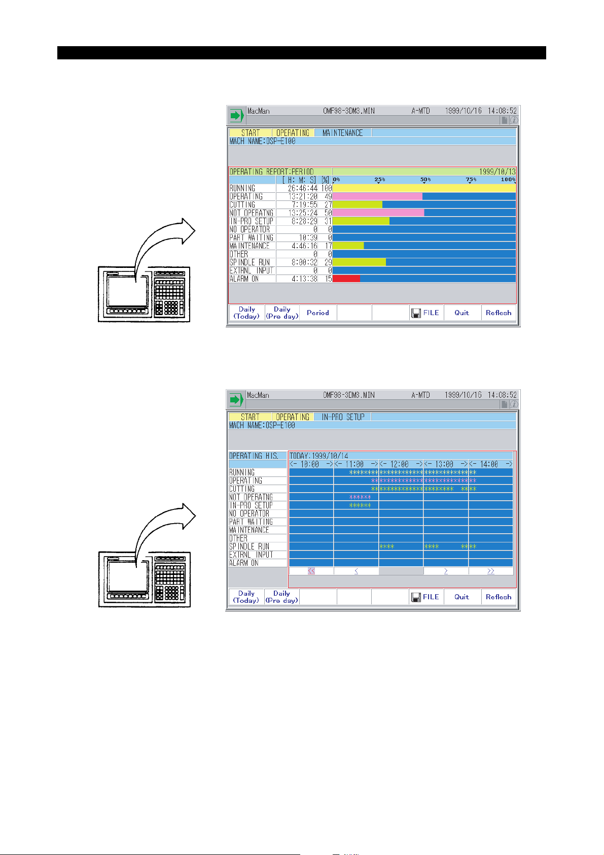
(2) Operating Report
Operating status is displayed in bar graph.
4345-E P-2
SECTION 1 MacMan
(3) Operating History
Operating status is displayed in time chart.
EIOSPKKU1001R01
EIOSPKKU1002R01
Page 10
2. MacMan Slashes Down Time
4345-E P-3
SECTION 1 MacMan
Precise understanding of the situation of a trouble is the key to pin-pointed troubleshooting and
quick recovery of the machine operation.
Using the MacMan, you can get the information necessary for troubleshooting to be output onto MSDOS formatted floppy disk.
• If you output the information to the floppy disk, the information can be analyzed by using a per-
sonal computer by either yourself or Okuma service technician.
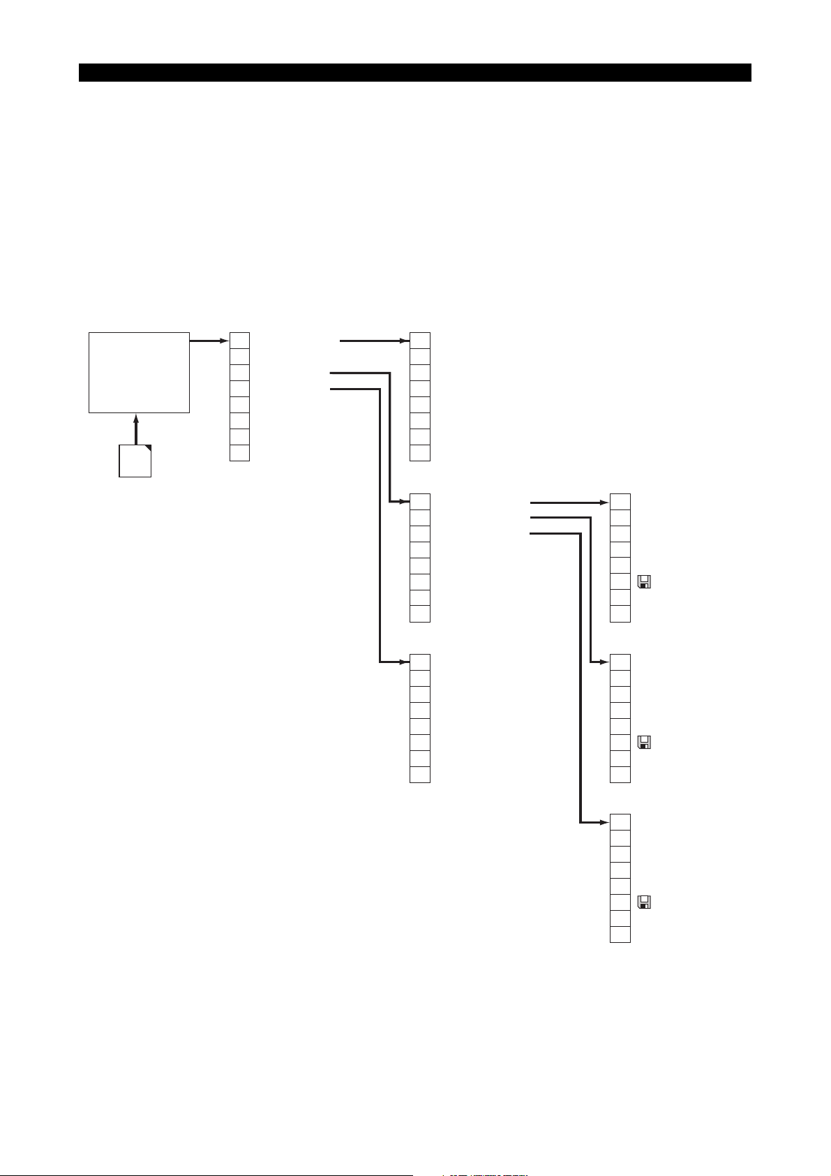
3. Screen Transition Diagram
[Selecting the reason for not-operating]
F1
Which Non op.
MaMan
MAIN
Mac
Man
(*1)
This function is displayed for network function
(IT plaza set,DNC-T etc.) specification only.
F2
F3
Report Info.
F4
Trouble Info.
F5
F6
Network (*1)
F7
F8
Refresh
[Report menu]
F1
IN-PRO SETUP
F2
NO OPERATOR
F3
PART WAITING
F4
MAINTENANCE
F5
OTHER
F6
F7
Quit
F8
F1
Machine Report
F2
Operate Report
F3
Operate History
F4
F5
F6
F7
Quit -> Return to the previous screen
F8
Eeospkku1003
Eeospkku1004
[Machining report]
F1
Daily (Today)
F2
Daily (Pre day)
F3
Period
F4
F5
F6
File
F7
Quit -> Return to the previous screen
F8
Refresh
[Trouble information menu]
F1
NC status at alaem
F2
Current NC status
F3
Alarm History
F4
Operation History
F5
Variable History
F6
System configuration
F7
Quit -> Return to the previous screen
F8
[Operation report]
F1
Daily (Today)
F2
Daily (Pre day)
F3
Period
F4
F5
F6
File
F7
Quit -> Return to the previous screen
F8
Refresh
[Operating History]
F1
Daily (Today)
F2
Daily (Pre day)
F3
F4
F5
F6
File
F7
Quit -> Return to the previous screen
F8
Refresh
EIOSPKKU1004R01
Page 11
SECTION 2 MacMan MAIN SCREEN
SECTION 2 MacMan MAIN SCREEN
4345-E P-4
Eeospkku2001
EIOSPKKU2001R01
Page 12
1. Machining Status
4345-E P-5
SECTION 2 MacMan MAIN SCREEN
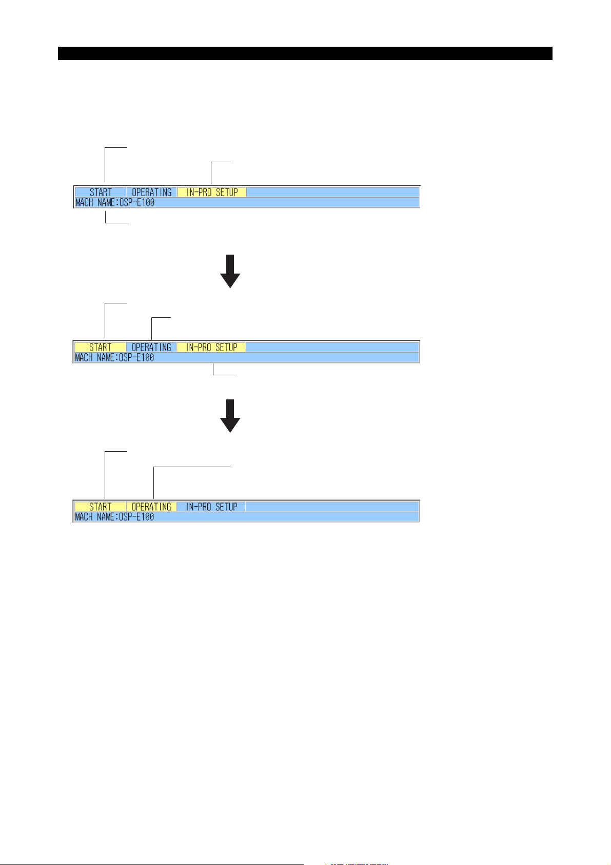
(1) On the screen, whether or not a program has been selected is indicated by "START" and
Eeospkku2002
whether or not a program is being executed is indicated by "OPERATING".
The area indicating the status explained above is common to all display screens.
A main program has not been selected (NOT START status).
A main program is not being executed (NOT OPERATING status).
The reason for "not-operating status" is in-process setup.
To be set by selecting "REPORT/PRINTER" on the PREFERENCE SETTING screen.
The default machine name is "MC.NAME".
Date and time (today, current time)
Selecting a program
A main program has been selected (START status).
A main program is not being executed (NOT OPERATING status).
The reason for "not-operating status" is in-process setup.
Reason for "not-operating" is displayed here:
IN-PRO SETUP, NO OPERATOR, PART WAITING, MAINTENANCE, or OTHER
Executing the program
The main program has been selected (START status).
The main program is being executed (OPERATING status).
After the completion of the main program execution,
the machine enters the NOT OPERATING status due to in-process setup.
EIOSPKKU2002R01
Page 13

2. Recent Machining Report
4345-E P-6
SECTION 2 MacMan MAIN SCREEN
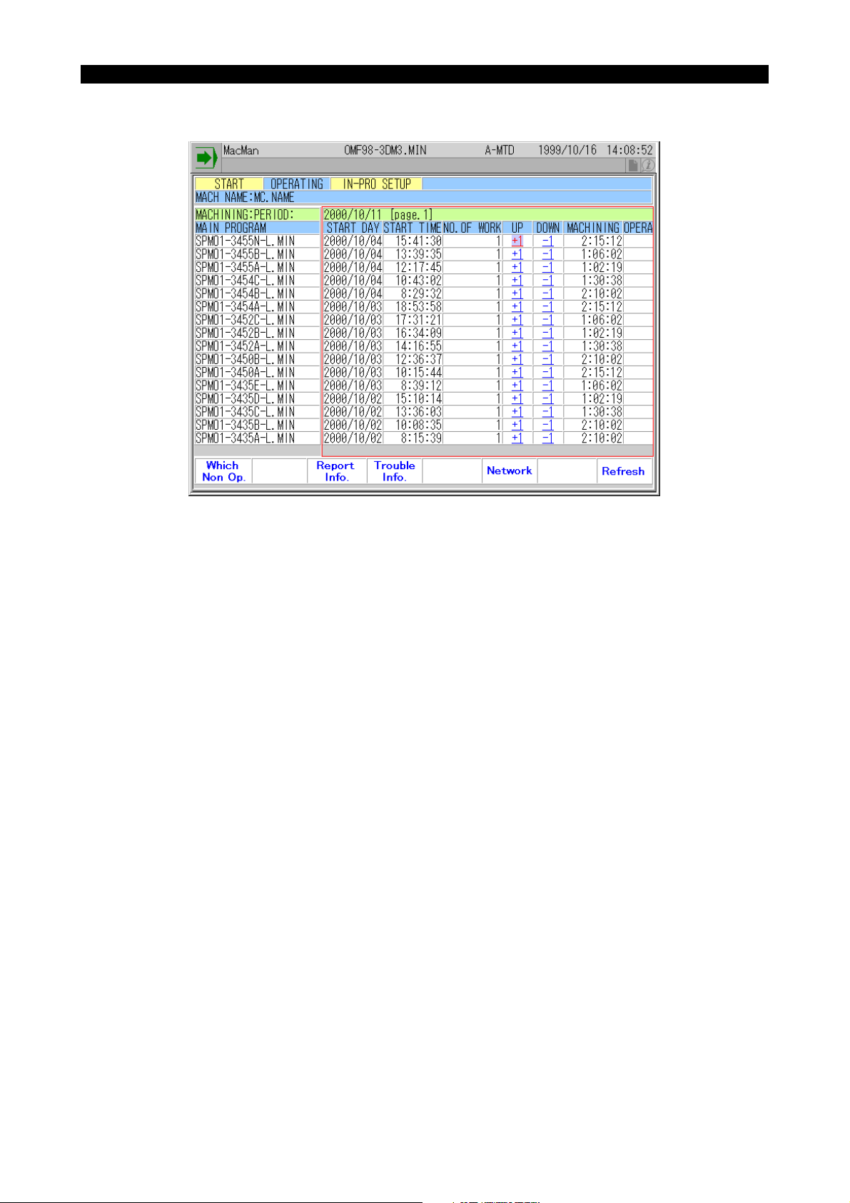
(1) Recent machining report is displayed.(up to 16 main programs)
Machining report for the program currently selected
• MAIN PROGRAM
The file name of the main program having been selected
• START DAY
Date of the main program selection [year/month/day]
• START TIME
Time of the main program selection [hour:minute:second]
• NO. OF WORK
The number of times the M02 or M30 command has been executed
Execution of the M02 or M30 command in the machine lock mode operation and dry run
mode operation (NC lathe) is not counted.
• OPERATING %
Percentage of machine operating time in reference to power ON time [%]
(Operating % = Machine operating time (OPERATING) / Power ON time (RUNNING) X 100)
Eeospkku2003
EIOSPKKU2003R01
• RUNNING
Length of time for which power supply to the NC has been ON [hours:minutes:seconds]
(Length of time for which main program has been selected)
• OPERATING
Length of time for which a main program has been executed [hours:minutes:seconds]
• CUTTING
Length of time for which an axis has been moved at a cutting feedrate [hours:minutes:seconds]
Length of time an axis has been moved at a cutting feedrate in the machine lock mode or dry
run mode (NC lathe) is not counted.
• CYCLE TIME
Length of time for which power has been ON for producing one piece of workpiece
[hours:minutes:seconds/pc.]
(Cycle time = Power on time (RUNNING) / No. of workpieces (NO. OF WORK))
• MACHINING
Length of operating time used for producing one piece of workpiece [hours:minutes:seconds/pc.]
(Machining time = Operating time (RUNNING) / No. of workpieces (NO. OF WORK))
(2) The items of report are scrolled right or left by pressing the "right" or "left" cursor key (1 item/
cursor key operation). Note that the MAIN PROGRAM is not shifted.
Page 14
4345-E P-7
SECTION 2 MacMan MAIN SCREEN
3.
Adjusting the Number of Work Count
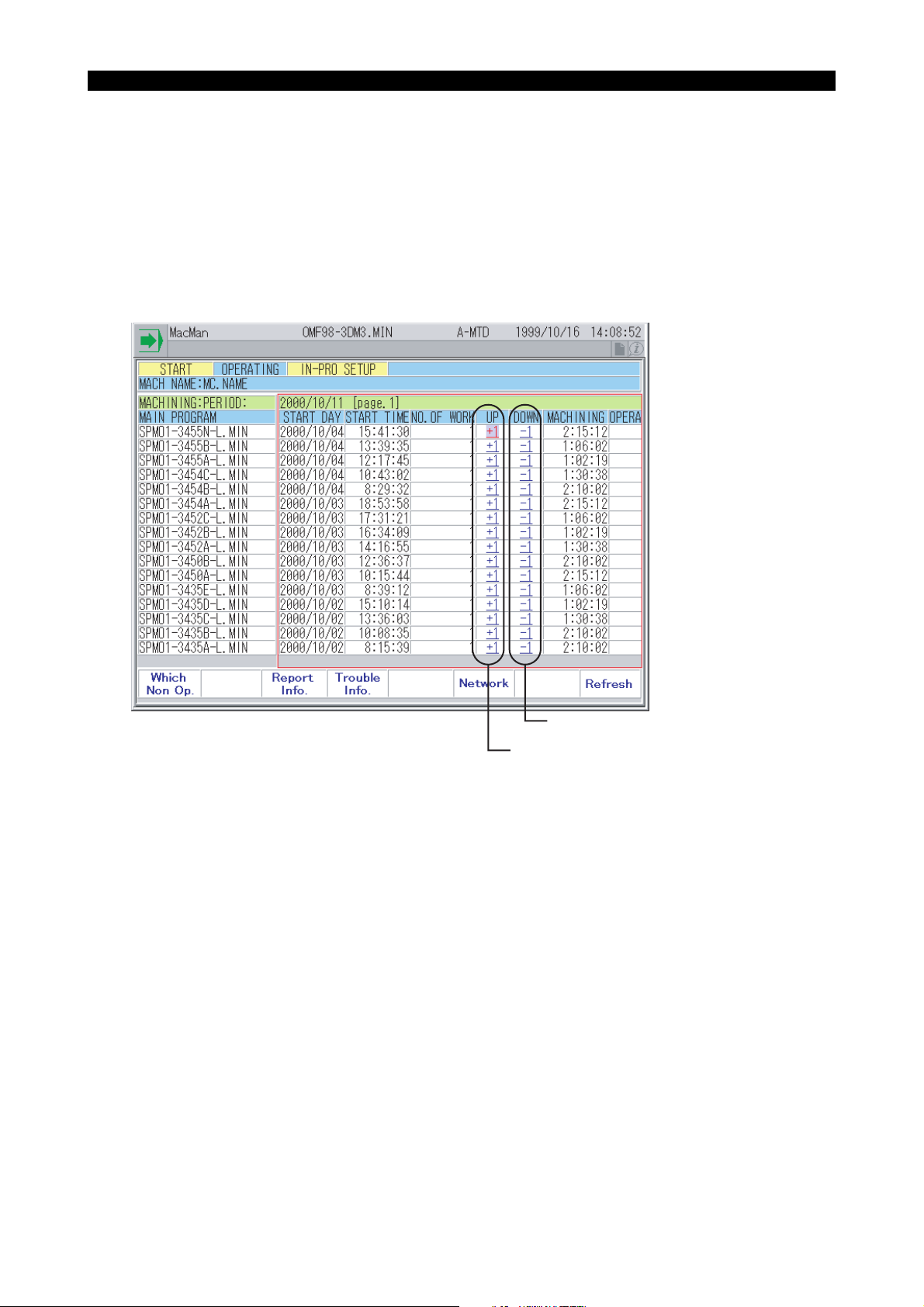
You can correct the report data if the number of machined parts recorded in the machining report
differs from the number of actually machined parts.
When including the test-cut parts in the total number, for instance, you can increase (+1) the number
of parts. Conversely, when defective workpieces are found, you can decrease (-1) the number.
To correct the number, use the arrow keys and move the cursor to the [+1] or [-1] button for the
report data that you want to increase or decrease. Then, press the WRITE key.
If this page does not include the data that you want to correct, select a required report from the
report information screen.
Eeospkku2004
Decreases the number of parts by one.
Increases the number of parts by one.
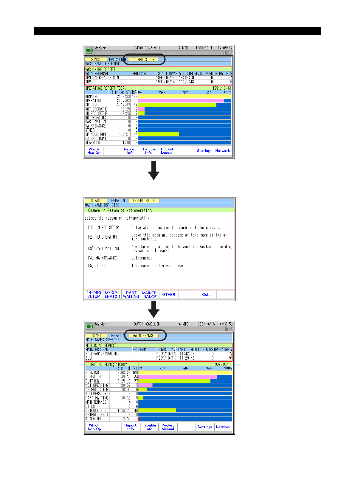
4. Changing the Reason of Not-operating Status
The current reason is in-process setup. Now, you are starting maintenance and the reason must be
changed to maintenance accordingly.
EIOSPKKU2004R01
Eeospkku2005
Page 15
SECTION 2 MacMan MAIN SCREEN
Press the function key [F1] (Which Non Op.).
4345-E P-8
Press the function key [F4] (Maintenance).
EIOSPKKU2005R01
Page 16

4345-E P-9
SECTION 2 MacMan MAIN SCREEN
(1) Reasons for Not-operating Status
The MacMan provides five categories for the reasons for not-operating status.
• IN-PRO SETUP
Select this reason when you perform setup change by stopping the machine.
(Setup change performed without stopping the machine is called post-process setup.)
• NO OPERATOR
One operator usually takes care of tow or more machines. Select this reason when you must
go to another machine.
• PART WAITING
If a workpiece, cutting tool(s), and/or a workpiece holding device is not ready or is not supplied to the machine on time, the machine will not be able to operate until all of them are
supplied to it.
Select this reason if the machine has to be stopped in such status.
• MAINTENANCE
Select this reason if the machine has to be stopped due to maintenance.
• OTHER
Select this reason if the machine has to be stopped due to the reasons not given above.
(2) Changing the Reason Manually
If you want to change the reason for not-operating status, press function key [F1] (WHICH NON
OP) and input the code number heading the reason to be selected. For example, change the
reason to "MAINTENANCE" before you begin maintenance.
• After pressing function key [F1] (WHICH NON OP), if you do not want to change the reason,
simply press the [WRITE] key without keying in a code number.
• It is possible to change the reason for not-operating status while the machine is operating. If
you have to leave the machine while it is operating to take care of other machine, you can
change the reason to "NO OPERATOR" before you leave the machine.
(3) Changing the Reason Automatically
The MacMan can determine the reason for not-operating status automatically. If you select "INPROCESS SETUP" for the reason, you are not requested to change the reason while the
machine is operating continuously.
• Ordinary not-operating status, due to such as changing workpieces and removing chips, is
classified into "IN-PROCESS SETUP".
• Assume that you leave the machine, without changing the reason:
While you are not attending the machine, that situation is recognized by the NC from the fact
that none of keys on the NC operation panel has not been pressed for a period longer than
the parameter-set time. Upon recognition of this, the NC automatically changes to reason
from "IN-PROCESS SETUP" to "NO OPERATOR".
• If you come back to the machine for which the reason for not-operating has been changed to
"NO OPERATOR":
The NC recognizes that you have returned to the machine from the fact that a key on the NC
operation panel has been pressed. Then, the NC automatically switches the reason back to
"IN-PROCESS SETUP".
Page 17

4345-E P-10
SECTION 2 MacMan MAIN SCREEN
• If the reason for not-operating status is "PART WAITING", "MAINTENANCE", or "OTHER",
the automatic change function is not valid. If the machine has to be stopped, due to any of
these reasons, change the reason manually. When the machine restarts, change the reason for not-operating status manually again.
The initial parameters are so set that the NC does not automatically change the reason for
not-operating status. To make the NC change the reason automatically, select MacMan
PARAMETER in the parameter setting mode and set the required data at the following
parameters:
• USE NOT OPERATING ITEM FOR AUTO DECISION (0=NO,1=YES)
0 (No)
• TIME ALLOWED BEFORE DETERMINING NO OPERATOR PRESENT (hh:mm:ss)
00:20:00 (20 minutes)
Page 18

SECTION 3 REPORT INFORMATION DISPLAY
SECTION 3 REPORT INFORMATION DISPLAY
Eeospkku3001
4345-E P-11
EIOSPKKU3001R01
Press function key [F1], [F2], or [F3], and the corresponding machining or operation report screen is
displayed.
Machining Report
The report shows the progress of each of the selected main programs.
Program progress report:
• MAIN PROGRAM
The file name of the main program having been selected.
• START DAY
Date of the main program selection [year/month/day]
• START TIME
Time of the main program selection [hour:minute:second]
• NO. OF WORK
The number of times the M02 or M30 command has been executed
Execution of the M02 or M30 command in the machine lock mode operation and dry run mode
operation (NC lathe) is not counted.
• OPERATING %
Percentage of machine operating time in reference to power ON time [%]
(Operating % = Machine operating time (OPERATING) / Power ON time (RUNNING))
• RUNNING
Length of time for which power supply to the NC has been ON [hours:minutes:seconds]
(Length of time for which main program has been selected)
• OPERATING
Length of time for which a main program has been executed [hours:minutes:seconds]
Length of time the main program has been executed in the machine lock mode or dry run mode
(NC lathe) is not counted.
Page 19

4345-E P-12
SECTION 3 REPORT INFORMATION DISPLAY
• CUTTING
Length of time for which an axis has been moved at a cutting feedrate [hours:minutes:seconds]
Length of time an axis has been moves at a cutting feedrate in the machine lock mode or dry
run mode (NC lathe) is not counted.
• CYCLE TIME
Length of time for which power has been ON for producing one piece of workpiece [hours:minutes:seconds/pc.]
(Cycle time = Power on time (RUNNING) / No. of workpieces (NO. OF WORK))
• MACHINING
Length of operating time used for producing one piece of workpiece [hours:minutes:seconds/
pc.]
(Machining time = Operating time (RUNNING) / No. of workpieces (NO. OF WORK))
Operating Report
The report shows the operating status of the machine.
Machine operating report:
• RUNNING
Length of time for which power supply to the NC has been ON [hours:minutes:seconds]
(Power ON (RUNNING) = OPERATING + NOT OPERATNG)
• OPERATING
Length of time for which a main program has been executed
Length of time the main program has been executed in the machine lock mode or dry run mode
(NC lathe) is not counted.
(OPERATING = CUTTING + Not cutting)
• CUTTING
Length of time for which an axis has been moved at a cutting feedrate [hours:minutes:seconds]
Length of time an axis has been moved at a cutting feedrate in the machine lock mode or dry
run mode (NC lathe) is not counted.
• NOT OPERATNG
Length of time for which a main program has not been executed
(NOT OPERATING = IN-PRO SETUP + NO OPERATOR + PART WAITING + MAINTENANCE
+ OTHER)
• IN-PRO SETUP
Constituent of not-operating time: machine has not been operating due to in-process setup.
• NO OPERATOR
Constituent of not-operating time: machine has not been operating due to no operator attendance.
• PART WAITING
Constituent of not-operating time: machine has not been operating due to waiting for workpiece
to be machined.
• MAINTENANCE
Constituent of not-operating time: machine has not been operating due to machine maintenance.
• OTHER
Constituent of not-operating time: machine has not been operating due to reasons not classified
into the items indicated above.
• SPINDLE RUN
Length of time for which the spindle has been rotating
Length of time the spindle has been rotating in the machine lock mode is not counted.
Page 20

4345-E P-13
SECTION 3 REPORT INFORMATION DISPLAY
• EXTERNAL INPUT
Length of time for which an external input signal has been ON
• ALARM ON
Length of time for which the NC has been in an alarm state (alarm A, alarm B, alarm C)
Operating History
The operating history shows the operating status (ON/OFF) of the machine using the time chart in
intervals of 10 minutes.
Machine history:
• RUNNING
Length of time for which power supply to the NC has been ON
• OPERATING
Length of time for which a main program has been executed
Length of time the main program has been executed in the machine lock mode or dry run mode
(NC lathe) is not counted.
• CUTTING
Length of time for which an axis has been moved at a cutting feedrate
Length of time an axis has been moved at a cutting feedrate in the machine lock mode or dry
run mode (NC lathe) is not counted.
• NOT OPERATNG
Length of time for which a main program has not been executed
• IN-PRO SETUP
Constituent of not-operating time: machine has not been operating due to in-process setup.
• NO OPERATOR
Constituent of not-operating time: machine has not been operating due to no operator attendance.
• PART WAITING
Constituent of not-operating time: machine has not been operating due to waiting for workpiece
to be machined.
• MAINTENANCE
Constituent of not-operating time: machine has not been operating due to machine maintenance.
• OTHER
Constituent of not-operating time: machine has not been operating due to reasons not classified
into the items indicated above.
• SPINDLE RUN
Length of time for which the spindle has been rotating
Length of time the spindle has been rotating in the machine lock mode is not counted.
• EXTERNAL INPUT
Length of time for which an external input signal has been ON
• ALARM ON
Length of time for which the NC has been in an alarm state (alarm A, alarm B, alarm C)
(1) You can output the report information to the floppy disk.
• Simply press the function key [F6] ( File), and the operation report presently displayed on
the screen is output to the floppy disk. The default device and file names can be set at the
MacMan parameters displayed in the parameter setting mode. These parameters are factory-set so that the date is entered in the file name.
Page 21

SECTION 4 MACHINING REPORT DISPLAY
SECTION 4 MACHINING REPORT DISPLAY
1. Daily Machining Report (Today)
4345-E P-14
Eeospkku4001
EIOSPKKU4001R01
(1) The machining result of the main programs selected today is displayed for each main program
in the order the main programs selected later (START TIME).
• The first line in the first page shows the machining result of the main program presently
selected.
• When the screen is changed to the MACHINING REPORT screen, the DAILY MACHINING
REPORT (TODAY) screen is displayed.
Date (today)
EIOSPKKU4002R01
Page 22

4345-E P-15
SECTION 4 MACHINING REPORT DISPLAY
(2) The machining report consists of a main program file name and nine items showing the
progress of the main program. Since one line in the display screen in able to show a main program file name and four items, use the "left" and "right" cursor keys to scroll the screen to display the other items. Note that the main program file name stays displayed at the same column
even when the display of the items is scrolled.
"Left" cursor key
"Right" cursor key
EIOSPKKU4003R01
(3) One page of the machining report display page shows the information on 16 main programs. If
you have selected more than 16 main programs for a day, press the page key to display the
other pages.
EIOSPKKU4004R01
Page 23

SECTION 4 MACHINING REPORT DISPLAY
2. Daily Machining Report (Pre Day)
4345-E P-16
Eeospkku4002
EIOSPKKU4005R01
(1) The machining results of the main programs selected in the previous day are displayed in the
order of selection, with the latest one being the top (START TIME).
• The term previous day does not always mean "yesterday". It indicates the last day the NC
was operated. If the NC had been stopped for two days, the previous day refers to the day
three days before today.
• The functions of the cursor keys and the page keys are the same as those used in the
MACHINING REPORT (TODAY) screen.
Date (previous day)
EIOSPKKU4006R01
Page 24

3. Period Machining Report
4345-E P-17
SECTION 4 MACHINING REPORT DISPLAY
Eeospkku4003
EIOSPKKU4007R01
(1) The machining result of the main programs having been selected up to today is displayed for
each main program in the order the main programs selected later (START TIME).
• The first line in the first page shows the machining result of the main program presently
selected.
• One page of the report display shows the machining report of up to 16 main programs. In
this report.
• If the total number of the selected main programs exceeds 13, the report is given on the fol-
lowing pages which are accessible by pressing a cursor key or a page key. The functions of
the cursor keys and the page keys are the same as those used in the MACHINING
REPORT (TODAY) screen.
(2) The period machining report function is able to store the machining result information for up to
91 main programs, including the main program selected presently.
• If the memory has already stored the machining result information for 91 main programs,
selection of a new main program will cause the machining result information of the oldest
main program among the stored 91 main programs to be deleted. The machining report of
the newly selected main program is created instead.
• The machining report (today) is created by extracting the machining report of the main pro-
grams for which the START DAY is today from the period machining report.
• The machining report (pre day) is created by extracting the machining report of the main pro-
grams for which the START DAY is previous day from the period machining report.
Page 25

4. Output to Floppy Disk
4345-E P-18
SECTION 4 MACHINING REPORT DISPLAY
You can save the machining report displayed on the screen by outputting it to floppy disk.
(1) Insert an MS-DOS format floppy disk to the floppy disk drive. The machining report displayed
on the screen is output to the floppy disk.
(2) The machining report displayed on the screen can be output to the floppy disk by simply press-
ing function key [F6] ( File). The device name and the file name are set at the MacMan
parameters displayed in the parameter setting mode.
• Device name
The machining report is output to the device set at DEFAULT DEVICE. The initial setting for
DEFAULT DEVICE NAME is "FD0". Therefore, to output the machining report to a floppy
disk set in the FD0, you do not have to set the output device name.
• Output file name
The machining report to be output to the floppy disk is assigned the file name which is set at
DEFAULT FILE of the MacMan parameter displayed in the parameter setting mode. The initial setting for DEFAULT FILE NAME is:
Daily machining report file DW*Y*M*D. TXT
Period machining report file. TW*Y*M*D. TXT
Eeospkku4004
EIOSPKKU4008R01
If today is April 12, 1999 and the previous day is April 07, 1999, the actual file names to be
assigned are:
Daily machining report (today) DW990412. TXT
Daily machining report (pre day) DW990407.TXT
Period machining report TW990412.TXT
(3) If you output the machining report to the floppy disk (MS-DOS format), it is output in the text file.
Refer to Section 19. "OUTPUT FILES".
• If the report information is output in the text file, it can be displayed or analyzed using word
processor software.
Page 26

SECTION 5 OPERATING REPORT
1. Daily Operating Report (Today)
4345-E P-19
SECTION 5 OPERATING REPORT
Eeospkku5001
(1) Today's machine operating report is displayed.
When the screen is changed to the daily operating report screen, the DAILY OPERATING
REPORT (TODAY) screen is displayed.
Date (today)
Bar graph showing the rate of time to the NC running time
Rate of time to the NC running time [%]
Time [hours:minutes:seconds]
EIOSPKKU5001R01
EIOSPKKU5002R01
Page 27

2. Daily Operating Report (Pre Day)
4345-E P-20
SECTION 5 OPERATING REPORT
Eeospkku5002
EIOSPKKU5003R01
(1) The machine operating report of the previous day is displayed.
The term previous day does not always indicate yesterday. If the NC is turned on after it has
been stopped for two days, the previous day means the day two days before yesterday.
Date (previous day)
Bar graph indicating the ratio
Ratio to RUNNING TIME [%]
Time [hours:minutes:seconds]
EIOSPKKU5004R01
Page 28

3. Period Operating Report
4345-E P-21
SECTION 5 OPERATING REPORT
Eeospkku5003
EIOSPKKU5005R01
(1) The total operating time for the period up to today is displayed.
Start day of data accumulation
Bar graph showing the rate of time to the NC running time
Rate of time to the NC running time [%]
Time [hours:minutes:seconds]
EIOSPKKU5006R01
Page 29

4345-E P-22
SECTION 5 OPERATING REPORT
(2) Operating Time in the Period Operating Report
The operating time of each item displayed on the operating report is the accumulated time from
the day the operating report was cleared last. When the NC is turned on in the same day set as
the clear date, the period operating report is cleared and the operating time is accumulated
from "0".
• The period operating report clear day is set at a MacMan Parameter displayed in the param-
eter setting mode.
• The period operating report is cleared at the first power on operation to the NC on the same
day as set for the OPERATING REPORT CLEAR DAY. The report is not cleared in the succeeding power on operation.
• Make sure that no holiday is set as the OPERATING REPORT CLEAR DAY. The operating
report is not cleared only when the NC is turned on in the preset report clear date.
Example: setting the period operating report clear day
• To use the period operating report as the weekly report, set the date of Monday of the next
week (Tuesday, if Monday is holiday) for PERIOD OPERATING REPORT CLEAR DAY.
• To use the period operating report as the monthly report, set the first day of the next month (the
second day if the first day is holiday) for PERIOD OPERATING REPORT CLEAR DAY.
• To collect the result of improvements in operation, set the next day on the day when improve-
ment preparation has been finished.
Page 30

SECTION 6 OPERATING HISTORY
1. Daily Operating History (Today)
4345-E P-23
SECTION 6 OPERATING HISTORY
Eeospkku6001
(1) The machine operating status for one day (today) is displayed in time chart.
The operating status of the machine (ON/OFF) is checked in every 10 minutes and the results
of the check are displayed on the screen in time chart.
11:00
Date of report (today)
NC was ON, but Main program was not executed.
Reason: In-process setup
11:30
12:00
EIOSPKKU6001R01
EIOSPKKU6002R01
Page 31

4345-E P-24
SECTION 6 OPERATING HISTORY
(2) A screen shows the operating history for five hours. To display the history before or after the
displayed time zone, locate the cursor on [<<] [<] [>] [>>] using the cursor keys with left and
right arrows, and press WRITE.
Goes back
by 4 hours
Goes back by
1 hour
Advance by
1 hour
Advance by
4 hours
EIOSPKKU6003R01
Page 32

2. Daily Operating History (Pre Day)
4345-E P-25
SECTION 6 OPERATING HISTORY
Eeospkku6002
(1) The machine operating status for one day (previous day) is displayed in time chart.
The operating status of the machine (ON/OFF) is checked in every 10 minutes and the results
of the check are displayed on the screen in time chart.
• The term previous day does not always indicate yesterday. If the NC is turned on after it has
been stopped for two days, the previous day means the day three days before yesterday.
• The operating history for 5 hours is displayed on the screen. The display can be scrolled to
view the history of other operating hours by using the "right" and "left" cursor keys.
You can scroll the screen in the same manner as explained in 10-1. "Daily Operating History
(Today)".
15:00
Date of report (previous day)
15:30
16:00
EIOSPKKU6004R01
NC was ON, but Main program was not executed.
Reason: In-process setup
EIOSPKKU6005R01
Page 33

SECTION 7 TROUBLESHOOTING INFORMATION
SECTION 7 TROUBLESHOOTING INFORMATION
Eeospkku7002
4345-E P-26
EIOSPKKU7001R01
(1) On the TROUBLESHOOTING INFORMATION screen, press function keys [F1] to [F6] accord-
ing to the function you want to call. The information which will help you check and troubleshoot
the problem is displayed.
• To check the alarm occurrence time and nature of alarm:
ALARM HISTORY
• To check the alarm occurrence time and type of operation involved:
OPERATE HISTORY
a. [F3] (ALARM HISTORY)
The alarm history is displayed on the screen. At each occurrence of an alarm, the data
which identify the alarm are logged - date, time, alarm number, alarm code, and alarm
character string.
It is possible to output the alarm history to the floppy disk.
b. [F4] (OPERATE HISTORY)
The screen shows two kinds of operation histories. The operation history can be also output to the floppy disk.
OPERATING PANEL : NC operation panel keys that have been pressed
I/O SIGNALS : ON/OFF status of the I/O signals
(2) You can output the trouble information to the floppy disk.
• Simply press function key [F6] ( File), and the trouble information isoutput to the floppy
disk. The information presently displayed is output. The device name and the file name are
set on the PARAMETER SETTING screen. With the setting made at the shipping, date is
entered to the file name.
Page 34

SECTION 8 ALARM HISTORY
4345-E P-27
SECTION 8 ALARM HISTORY
Eeospkkua001
1. Displaying the Alarm History
You can back track the occurrence of alarms.
(1) At each occurrence of an alarm, the data which identify the alarm are logged and displayed on
the screen. The information which identifies individual alarms consists of the date, time, alarm
number, alarm code, and alarm character string.
(2) On the ALARM HISTORY screen, up to 16 sets of alarm information are displayed. To view
other alarms which are not displayed on the screen, press function key [F5] (Page ↓).
EIOSPKKUA001R01
Eeospkkua002
Page 35

2. Changing Logged Alarm Levels
4345-E P-28
SECTION 8 ALARM HISTORY
The alarm levels logged in the alarm history can be changed.
The factory-set alarm levels to be logged in the alarm history are alarms A, B, C, and D.
Eeospkkua004
Lathes
Change the alarm levels on the OPTIONAL PARAMETER (OTHER FUNCTION) screen displayed
in the parameter setting mode.
Select the alarm level from:
Alarm A, B, C, D
Alarm A, B, C
Alarm A, B
Alarm A
EIOSPKKUA003R01
Page 36

4345-E P-29
SECTION 8 ALARM HISTORY
Machining Centers
Change the alarm levels on the NC OPTIONAL PARAMETER (DISPLAY RELATION PARAMETER) screen displayed in the parameter setting mode.
Select the alarm level from:
Alarm A, B, C, D
Alarm A, B, C
Alarm A, B
Alarm A
EIOSPKKUA004R01
Page 37

SECTION 9 OPERATION HISTORY
1. Operate Panel
4345-E P-30
SECTION 9 OPERATION HISTORY
Eeospkkub003
EIOSPKKUB003R01
(1) The following operations are records as the operation panel history with the date and time.
1) Key input
2) Operation on the screen components
3) Function key input
4) MDI input
5) Occurrence of error
6) Mode change
7) Depression of help key
8) Execution of one-touch window close
9) Others, including changes between turret A and turret B
<<Limitations>>
The panel operations, however, are not recorded on the following screens:
1) One-Touch IGF-XM screen
2) OSP browser screen (for MacMan or Pocket Manual)
(2) History of a key input is displayed as follows:
> "Key name"
The illustration below shows an example displayed when depression of the cursor key [↓] has
been recorded.
EIOSPKKUB005R01
Page 38

4345-E P-31
SECTION 9 OPERATION HISTORY
Table 1 shows the keys and the corresponding character strings displayed as a record.
(3) The MacMan System also records the operations on the screen components such as input in
the TextBox, changing ON/OFF status in the CheckBox, changing number in the SelectionBox
or ListBox. These records are displayed as follows:
"Screen component name": "Operation"
If, for example, you turned on a CheckBox, the operation record is displayed as illustrated
below.
EIOSPKKUB007R01
In the above illustration, (Table (1, 1)) at the end is the internal data of the system and not
related with your operation.
(4) Depression of a function key is displayed as follows:
"Function key number" ["Function key label"]
When a window is open, the MacMan System shows all the screen components in the window
to which the cursor can be moved. When no window is open, it shows the state of cursorlocated screen components.
<Example 1> Main program selection screen (lathe)
EIOSPKKUB009R01
If the function key [F7] (OK) is pressed on the above example screen, the following record is
displayed.
EIOSPKKUB010R01
Page 39

4345-E P-32
SECTION 9 OPERATION HISTORY
(5) Record of manual data input is displayed as follows:
MDI Input: "Input character string"
(6) If an error occurs, the error number and the error character-string are displayed as an error
record.
The illustration below shows an example of record displayed when Error "337 floppy ready"
occurred.
EIOSPKKUB012R01
(7) Record of mode change is displayed as follows:
Mode Change: "Mode name"
(8) When a help screen is opened by depression of the help key, the following record is displayed:
Help
When the help screen is closed by re-depression of the help key, the record is displayed as follows:
Mode Change: "Mode name"
(9) When a window is closed using the one-touch window close function (pressing the same mode
key as the currently selected one when the window is open), the record is displayed as follows:
One-touch Window Close: "Mode name"
(10) When a turret is changed on the lathe by depression of turret A key or turret B key, the record is
displayed as follows:
A-Turret
B-Turret
(when turret A is selected)
(when turret B is selected)
Page 40

SECTION 10 PARAMETER SETTING
SECTION 10 PARAMETER SETTING
4345-E P-33
Eeospkkue001
EIOSPKKUE001R01
(1) Press a proper function key to access the required function. The function keys are summarized
below.
a) REPORT DATA
Used to set the machine names and the parameters needed for collecting the operating
data.
b) OUTPUT DATA
Used to set the default device name and the default file name of the various operation data
files and various trouble information files.
c) INIT
Used to initialize (or clear) the history data of report information or trouble information.
Page 41

1. REPORT DATA
4345-E P-34
SECTION 10 PARAMETER SETTING
Eeospkkue002
MACHINE NAME
• Explanation
The machine name set here is displayed on all screens of the cell operation management function. The machine name is described in the file when outputting the report or troubleshooting
information to a floppy disk. When outputting the report or troubleshooting information to a
printer, the machine name is printed at the head of the print-out.
• Setting
Within eight alphanumeric characters
EIOSPKKUE002R01
Page 42

4345-E P-35
SECTION 10 PARAMETER SETTING
OPERATING REPORT CLEAR DAY
• Explanation
If the date of today agrees with the date set for "OPERATING REPORT CLEAR DATE", the
period operating report in the memory is cleared when the NC is turned on.
• Setting
Ten characters (fixed)
If the number of digits of a number used to express the month or day is not two, prefix "0" to the
number.
Examples: 1999/07/30 Acceptable
1999/7/30 Not acceptable
USE NOT OPERATING ITEM FOR AUTO DECISION
TIME ALLOWED BEFORE DETERMINING NO OPERATOR PRESENT
• Explanation
If you set [YES] for "USE NOT OPERATING ITEM FOR AUTO DECISION", the reasons for notoperating status are automatically determined as follows:
• If a key on the NC operation panel has not been pressed for the period set for "TIME
ALLOWED BEFORE DETERMINING NO OPERATOR PRESENT", the reason for not-operating status is changed to "NO OPERATOR". Note that this automatic change is made only
when the current reason is "IN-PRO SETUP".
• If a key on the NC operation panel is pressed, the reason for not-operating is automatically
changed to "IN-PRO SETUP". Note that this automatic change is made only when the current reason is "NO OPERATOR".
• Setting
Eight characters (fixed)
If the number of digits of a number used to express the time is not two, prefix "0" to the number.
Examples: 08:59:00 Acceptable
8:59:00 Not acceptable
Page 43

2. OUTPUT DATA
4345-E P-36
SECTION 10 PARAMETER SETTING
Page 1
(1) DEFAULT DEVICE NAME
• Explanation
The default name of the device where the file is output if no device name is specified for file output operation is set.
Note that the setting simply specifies the device name and the status of the floppy disk drive is
not checked. This means the floppy disk drive may not be installed even if the setting is made.
• Setting
FD0: to FD9:
Eeospkkue007
EIOSPKKUE003R01
(2) DAILY MACHINING REPORT FILE: DEFAULT FILE NAME
(3) DAILY OPERATING REPORT FILE: DEFAULT FILE NAME
(4) DAILY OPERATING HISTORY FILE: DEFAULT FILE NAME
Page 2
(5) PERIOD MACHINING REPORT FILE: DEFAULT FILE NAME
(6) PERIOD OPERATING FILE: DEFAULT FILE NAME
EIOSPKKUE004R01
Page 44

4345-E P-37
SECTION 10 PARAMETER SETTING
Page 3
(7) ALARM HISTORY FILE: DEFAULT FILE NAME
(8) OPERATION PANEL HISTORY FILE: DEFAULT FILE NAME
• Explanation
The default names of the files used to output the report or troubleshooting information to the
floppy disk. Since the report and troubleshooting information are output to the MS-DOS format
floppy disk, the default file names to be set must conform to the rule of MS-DOS.
EIOSPKKUE005R01
• Setting
For a name, within 65 characters of alphanumerics which are preceded and followed by the
back slash code () can be input. Set a file name following the path name. Note that the directory
name and path name must conform to the MS-DOS rule.
\ABCDEFGH.TXT
Path name File name
\PART13.DIR\WORK954.DIR\RP.TXT
Path name File name
EIOSPKKUE008R01
Page 45

4345-E P-38
SECTION 10 PARAMETER SETTING
If you specify a specific character (Y, M, D, h, m, s) following an asterisk (*), it is replaced with a
two-digit number.
*Y : Year (Example: 1999, July 30 -> 99)
*M : Month (Example: 1999, July 30 -> 07)
*D : Date (Example: 1999, July 30 -> 30)
*h : Hour (Example: 8:34:52 -> 08)
*m : Minute (Example: 8:34:52 -> 34)
*s : Second (Example: 8:34:52 -> 52)
Year/month/day : Today if DAILY REPORT (TODAY) or PERIOD REPORT is
output.
Previous day if DAILY REPORT (PRE DAY) is output.
Hour/minute/second : The time at which the file is output.
Example 1: To output DAILY OPERATING REPORT (TODAY) in July 30th of 1999
DW*Y*M*D.TXT’DW990730.TXT
Example 2: To output DAILY OPERATING REPORT (PRE DAY) in July 30th of 1999 (date
of previous day: July 29th)
DW*Y*M*D.TXT’ DW990729.TXT
Example 3: To output the ALARM HISTORY at 13:30:48 in July 30th of 1999
AL*h*m*s.D*D ’ AL133048.D30
Page 46

3. Initialization
4345-E P-39
SECTION 10 PARAMETER SETTING
Eeospkkue008
EIOSPKKUE009R01
ALL INFO CLEAR
Turning on this check box clears all the report information and trouble information in G buffer.
OPERATING REPORT (TODAY, PRE.DAY, PERIOD)
Turning on this check box clears the today, pre day, and period machining report in G buffer.
MACHINING REPORT (TODAY, PRE.DAY, PERIOD)
Turning on this check box clears the today, pre day, and period machining report in G buffer.
OPERATING HISTORY (TODAY, PRE. DAY)
Turning on this check box clears the today and pre-day machining history in G buffer.
OPERATION HISTORY (OPERATING PANEL, I/O SIGNALS)
Turning on this check box clears the operation panel and the I/O signal operation history in G buffer.
Page 47

LIST OF PUBLICATIONS
Publication No. Date Edition
4345-E January 2000 1st
4345-E-R1 August 2000 2nd
4345-E-R2 Octobrt 2000 3rd
4345-E-R3 May 2001 4th
4345-E-R4 November 2001 5th
4345-E-R5 May 2002 6th
This manual may be at variance with the actual product due to specification or
design changes.
Please also note that pecifications are subject to change without notice.
If you requireclarification or further explanation of any point in this manual, please
contact your OKUMA representative.
 Loading...