

Page 1

GAUGING SYSTEMS
OSP-E100M / OSP-E10M
INSTRUCTION MANUAL
(8th Edition)
Pub No. 4297-E-R6 (ME51-221-R8) Aug. 2004
Page 2

SAFETY PRECAUTIONS
4297-E P-(i)
SAFETY PRECAUTIONS
The machine is equipped with safety devices which serve to protect personnel and the machine
itself from hazards arising from unforeseen accidents. However, operators must not rely exclusively
on these safety devices: they must also become fully familiar with the safety guidelines presented
below to ensure accident-free operation.
This instruction manual and the warning signs attached to the machine cover only those hazards
which Okuma can predict. Be aware that they do not cover all possible hazards.
1. Precautions Relating to Machine Installation
(1) Install the machine at a site where the following conditions (the conditions for achievement of
the guaranteed accuracy) apply.
• Ambient temperature: 17 to 25°C
• Ambient humidity: 40% to 75% at 20°C (no condensation)
• Site not subject to direct sunlight or excessive vibration; environment as free of dust, acid,
corrosive gases, and salt spray as possible.
(2) Prepare a primary power supply that complies with the following requirements.
• Voltage: 200 V
• Voltage fluctuation: ±10% max.
• Power supply frequency: 50/60 Hz
• Do not draw the primary power supply from a distribution panel that also supplies a major
noise source (for example, an electric welder or electric discharge machine) since this could
cause malfunction of the CNC unit.
Eeoemr5pl001
Eeoemr5pl002
• If possible, connect the machine to a ground not used by any other equipment. If there is no
choice but to use a common ground, the other equipment must not generate a large amount
of noise (such as an electric welder or electric discharge machine).
(3) Installation Environment
Observe the following points when installing the control enclosure.
• Make sure that the CNC unit will not be subject to direct sunlight.
• Make sure that the control enclosure will not be splashed with chips, water, or oil.
• Make sure that the control enclosure and operation panel are not subject to excessive vibra-
tions or shock.
• The permissible ambient temperature range for the control enclosure is 0 to 40°C.
• The permissible ambient humidity range for the control enclosure is 30 to 95% (no conden-
sation).
• The maximum altitude at which the control enclosure can be used is 1000 m (3281ft.).
2. Points to Check before Turning on the Power
(1) Close all the doors of the control enclosure and operation panel to prevent the entry of water,
chips, and dust.
(2) Make absolutely sure that there is nobody near the moving parts of the machine, and that there
are no obstacles around the machine, before starting machine operation.
Eeoemr5pl003
(3) When turning on the power, turn on the main power disconnect switch first, then the CONTROL
ON switch on the operation panel.
Page 3

3. Precautions Relating to Operation
4297-E P-(ii)
SAFETY PRECAUTIONS
(1) After turning on the power, carry out inspection and adjustment in accordance with the daily
inspection procedure described in this instruction manual.
(2) Use tools whose dimensions and type are appropriate for the work undertaken and the machine
specifications. Do not use badly worn tools since they can cause accidents.
(3) Do not, for any reason, touch the spindle or tool while spindle indexing is in progress since the
spindle could rotate: this is dangerous.
(4) Check that the workpiece and tool are properly secured.
(5) Never touch a workpiece or tool while it is rotating: this is extremely dangerous.
(6) Do not remove chips by hand while machining is in progress since this is dangerous. Always
stop the machine first, then remove the chips with a brush or broom.
(7) Do not operate the machine with any of the safety devices removed. Do not operate the
machine with any of the covers removed unless it is necessary to do so.
(8) Always stop the machine before mounting or removing a tool.
(9) Do not approach or touch any moving part of the machine while it is operating.
(10) Do not touch any switch or button with wet hands. This is extremely dangerous.
(11) Before using any switch or button on the operation panel, check that it is the one intended.
4. Precautions Relating to the ATC
(1) The tool clamps of the magazine, spindle, etc., are designed for reliability, but it is possible that
a tool could be released and fall in the event of an unforeseen accident, exposing you to danger:
do not touch or approach the ATC mechanism during ATC operation.
(2) Always inspect and change tools in the magazine in the manual magazine interrupt mode.
Eeoemr5pl004
Eeoemr5pl010
(3) Remove chips adhering to the magazine at appropriate intervals since they can cause misoper-
ation. Do not use compressed air to remove these chips since it will only push the chips further
in.
(4) If the ATC stops during operation for some reason and it has to be inspected without turning the
power off, do not touch the ATC since it may start moving suddenly.
5. On Finishing Work
(1) On finishing work, clean the vicinity of the machine.
(2) Return the ATC, APC and other equipment to the predetermined retraction position.
(3) Always turn off the power to the machine before leaving it.
(4) To turn off the power, turn off the CONTROL ON switch on the operation panel first, then the
main power disconnect switch.
Eeoemr5pl005
Page 4

4297-E P-(iii)
SAFETY PRECAUTIONS
6. Precautions during Maintenance Inspection and When Trouble Occurs
In order to prevent unforeseen accidents, damage to the machine, etc., it is essential to observe the
following points when performing maintenance inspections or during checking when trouble has
occurred.
(1) When trouble occurs, press the emergency stop button on the operation panel to stop the
machine.
(2) Consult the person responsible for maintenance to determine what corrective measures need to
be taken.
(3) If two or more persons must work together, establish signals so that they can communicate to
confirm safety before proceeding to each new step.
(4) Use only the specified replacement parts and fuses.
(5) Always turn the power off before starting inspection or changing parts.
(6) When parts are removed during inspection or repair work, always replace them as they were
and secure them properly with their screws, etc.
(7) When carrying out inspections in which measuring instruments are used - for example voltage
checks - make sure the instrument is properly calibrated.
(8) Do not keep combustible materials or metals inside the control enclosure or terminal box.
(9) Check that cables and wires are free of damage: damaged cables and wires will cause current
leakage and electric shocks.
(10) Maintenance inside the Control Enclosure
a) Switch the main power disconnect switch OFF before opening the control enclosure door.
Eeoemr5pl006
b) Even when the main power disconnect switch is OFF, there may some residual charge in the
MCS drive unit (servo/spindle), and for this reason only service personnel are permitted to
perform any work on this unit. Even then, they must observe the following precautions.
• MCS drive unit (servo/spindle)
The residual voltage discharges two minutes after the main switch is turned OFF.
c) The control enclosure contains the NC unit, and the NC unit has a printed circuit board
whose memory stores the machining programs, parameters, etc. In order to ensure that the
contents of this memory will be retained even when the power is switched off, the memory is
supplied with power by a battery. Depending on how the printed circuit boards are handled,
the contents of the memory may be destroyed and for this reason only service personnel
should handle these boards.
(11) Periodic Inspection of the Control Enclosure
a) Cleaning the cooling unit
The cooling unit in the door of the control enclosure serves to prevent excessive temperature
rise inside the control enclosure and increase the reliability of the NC unit. Inspect the following points every three months.
• Is the fan motor inside the cooling unit working?
The motor is normal if there is a strong draft from the unit.
• Is the external air inlet blocked?
If it is blocked, clean it with compressed air.
Page 5

7. General Precautions
4297-E P-(iv)
SAFETY PRECAUTIONS
(1) Keep the vicinity of the machine clean and tidy.
(2) Wear appropriate clothing while working, and follow the instructions of someone with sufficient
training.
(3) Make sure that your clothes and hair cannot become entangled in the machine. Machine opera-
tors must wear safety equipment such as safety shoes and goggles.
(4) Machine operators must read the instruction manual carefully and make sure of the correct pro-
cedure before operating the machine.
(5) Memorize the position of the emergency stop button so that you can press it immediately at any
time and from any position.
(6) Do not access the inside of the control panel, transformer, motor, etc., since they contain high-
voltage terminals and other components which are extremely dangerous.
(7) If two or more persons must work together, establish signals so that they can communicate to
confirm safety before proceeding to each new step.
8. Symbols Used in This Manual
The following warning indications are used in this manual to draw attention to information of particular importance. Read the instructions marked with these symbols carefully and follow them.
DANGER
Indicates an imminent hazard which, if not avoided, will result in death or serious injury.
Eeoemr5pl007
Eeoemr5pl008
WARNING
CAUTION
NOTICE
Indicates hazards which, if not avoided, could result in death or serious injury.
Indicates hazards which, if not avoided, could result in minor injuries or damage to devices
or equipment.
Indicates precautions relating to operation or use.
Page 6

INTRODUCTION
4297-E P-(i)
INTRODUCTION
Thank you very much for choosing our CNC system. This numerical control system is a expandable
CNC with various features including a multi-main CPU system. Major features of the CNC system
are described below.
(1) Expandable CNC with a multi-main CPU system
A multi-main CPU system on which up to seven engines (main CPUs) can be mounted is used.
An excellent performance and cost effectiveness have been realized as a leader of increasingly
rapid and accurate machine tools. The CNC system can be adapted to any models and variations by changing the construction of the main CPUs. The machine is controlled by a built-in
PLC.
(2) Compact and highly reliable
The CNC system has become compact and highly reliable because of advanced hardware
technology, including UCMB (Universal Compact Main Board), I/O link, and servo link. The
‘variable software’ as a technical philosophy of the OSPs supported by a flash memory. Functions may be added to the CNC system as required after delivery.
(3) NC operation panels
The following types of NC operation panels are offered to improve the user-friendliness.
• Color CRT operation panels
• Thin color operation panels (horizontal)
• Thin color operation panels (vertical)
One or more of the above types may not be used for some models.
(4) Machining management functions
These functions contribute to the efficient operation of the CNC system and improve the profitability from small quantity production of multiple items and variable quantity production of variations. Major control functions are described below.
Eeoemr5an001
a) Reduction of setup time
With increase in small-volume production, machining data setting is more frequently
needed. The simplified file operation facilitates such troublesome operation. The documents
necessary for setup, such as work instructions, are displayed on the CNC system to eliminate the necessity of controlling drawings and further reduce the setup time.
b) Production Status Monitor
The progress and operation status can be checked on a real-time basis on the screen of the
CNC system.
c) Reduction of troubleshooting time
Correct information is quickly available for troubleshooting.
(5) Help functions
When an alarm is raised, press the help key to view the content of the alarm.
This helps take quick action against the alarm.
To operate the CNC system to its maximum performance, thoroughly read and understand this
instruction manual before use.
Keep this instruction manual at hand so that it will be available when you need a help.
Screens
Different screens are used for different models. Therefore, the
screens used on your CNC system may differ from those shown in
this manual.
Page 7

TABLE OF CONTENTS
TABLE OF CONTENTS
SECTION 1 AUTOMATIC TOOL LENGTH OFFSET/AUTOMATIC TOOL
BREAKAGE DETECTION FUNCTION........................................................1
1. Overview ....................................................................................................................................... 1
1-1. Displaying the Result of Gauging .......................................................................................... 2
1-2. Function Menu ....................................................................................................................... 3
2. Automatic Tool Length Offset/Automatic Tool Breakage Detection Operation ............................. 9
2-1. Setting the Touch Sensor Zero Point .................................................................................. 10
2-2. Setting the Tool Pot No./Tool No. Table .............................................................................. 15
2-3. Operation Mode Designation............................................................................................... 16
2-4. Automatic Tool Length Offset Function ............................................................................... 18
2-5. Setting the Tool Change Position (Other Than MC-H) ........................................................ 22
2-6. Automatic Tool Breakage Detection .................................................................................... 23
2-7. Cycle Time Reduction for Automatic Tool Length Offset/Automatic Tool Breakage
Detection Cycle ................................................................................................................... 28
2-8. New Cycle Time Reduction Function for Automatic Tool Length Offset/Automatic Tool
Breakage Detection Cycle ................................................................................................... 30
4297-E P-(i)
3. Automatic Tool Length Offset/Automatic Tool Breakage Detection Function for
Special Tools and Attachments .................................................................................................. 34
3-1. Automatic Tool Length Offset/Automatic Tool Breakage Detection Function for
Horizontal Tools of MCM ..................................................................................................... 34
3-2. Operation for Automatic Tool Length Offset/Automatic Tool Breakage Detection on
B/C-axis Attachments, 90° Angular Attachments and Extension Attachments (Option) ..... 41
3-3. Operation of Automatic Tool Length Offset/Automatic Tool Breakage Detection with
30° Angular Attachments (Option)....................................................................................... 50
4. Y-axis Escape Position (MCM-B/MCR-B II/MCR-A/VH-40)........................................................ 62
4-1. Setting the Y-axis Escape Position...................................................................................... 62
4-2. Tool Movements during Automatic Tool Length Offset (Cutter Radius Compensation)/
Automatic Tool Breakage Detection Cycle .......................................................................... 63
5. Interference Prevention Measures for MCV-A/MCV-A II During Execution of the
Automatic Tool Length Offset/Automatic Tool Breakage Detection Cycle.................................. 64
5-1. Touch Sensor Operation Interlock ....................................................................................... 64
5-2. Measures against Interference during Execution of the Automatic Tool Length Offset/
Tool Breakage Detection Cycle ........................................................................................... 64
6. Variables Used in Subprograms .................................................................................................66
6-1. Table of Subprograms and Variables .................................................................................. 66
6-2. Table of Subprograms and Variables (MCM Horizontal Tools) ........................................... 69
6-3. How to Use Variables .......................................................................................................... 72
7. Cautions on Operation ................................................................................................................ 80
8. Program Examples ..................................................................................................................... 82
8-1. Automatic Tool Length Offset .............................................................................................. 82
Page 8

4297-E P-(ii)
TABLE OF CONTENTS
8-2. Automatic Tool Breakage Detection .................................................................................... 84
9. Alarm List.................................................................................................................................... 87
SECTION 2 AUTOMATIC GAUGING FUNCTION ........................................................94
1. Overview ..................................................................................................................................... 94
1-1. Dimension Check Function.................................................................................................. 94
1-2. Automatic Zero Offset Function........................................................................................... 94
2. Operation of the Automatic Gauging Function............................................................................ 95
2-1. Setting the Datum Hole Zero Point...................................................................................... 96
2-2. Touch Probe Radius Compensation.................................................................................... 98
2-3. Touch Probe Length Offset ............................................................................................... 103
2-4. Inner Diameter (ID) Gauging Function .............................................................................. 105
2-5. Outer Diameter (OD) Gauging Function ............................................................................ 107
2-6. End Face Gauging Cycle................................................................................................... 110
2-7. Saving of Gauging Cycle Results ...................................................................................... 115
2-8. Calculating the Center and Distance between Two Points................................................ 116
2-9. Calculating the Center and Distance between Two End Faces ........................................ 118
2-10.Automatic Zero Offset Function........................................................................................ 121
2-11.Copying the Touch Probe Offset Data.............................................................................. 122
3. Automatic Gauging Function for B-/C-axis, 90° Angular and
Extension Attachments (Option) ............................................................................................... 123
3-1. Automatic Gauging for 90° Angular Attachment and B-/C-axis Attachment (PAB=90°)... 125
3-2. Automatic Gauging for Extension Attachment and B-/C-axis Attachment (PAB=0°)......... 126
4. Power ON/OFF Cycle of Renishaw's Optical Touch Probe (MP7/MP9/MP10) ....................... 127
4-1. Power ON/OFF Cycle Commands .................................................................................... 127
4-2. Power ON/OFF Cycle Operation ....................................................................................... 128
5. Details ....................................................................................................................................... 130
5-1. Touch Probe Movements .................................................................................................. 130
5-2. Approach Speed to the Workpiece .................................................................................... 133
5-3. Variables Used in Subprograms ........................................................................................ 135
6. Touch Probe Safety Measures ................................................................................................. 147
6-1. Checking Proximity Switch Operation ............................................................................... 147
6-2. Replacing the Touch Probe Battery................................................................................... 148
7. Supplementary Information....................................................................................................... 149
8. Program Examples ................................................................................................................... 151
8-1. ID Gauging ........................................................................................................................ 151
8-2. OD Gauging....................................................................................................................... 152
8-3. End Face Gauging on Z-axis............................................................................................. 153
8-4. Distance between End Faces (X-axis direction) ................................................................ 154
8-5. Automatic Zero Offset........................................................................................................ 155
Page 9

4297-E P-(iii)
TABLE OF CONTENTS
8-6. Example Program for MCM Horizontal Spindle ................................................................. 156
9. Examples of Gauging Result Display ....................................................................................... 159
10.Alarm List .................................................................................................................................. 162
10-1.Alarm List.......................................................................................................................... 162
10-2.Gauging Impossible Cause Code Chart (Alarm B 2305) ................................................. 164
SECTION 3 GAUGING DATA OUTPUT FUNCTION ..................................................170
1. Overview ................................................................................................................................... 170
1-1. Parameters ........................................................................................................................ 170
1-2. Output Operation ............................................................................................................... 171
1-3. Example Program .............................................................................................................. 172
1-4. Example of Outputs ........................................................................................................... 173
1-5. Output Items ...................................................................................................................... 174
2. Interface Specifications for Connecting VP-600 ....................................................................... 175
2-1. Connection Diagram ..........................................................................................................175
2-2. Parameters ........................................................................................................................ 176
SECTION 4 GAUGING DATA OUTPUT TO FILE .......................................................177
1. Outline ...................................................................................................................................... 177
2. Parameters ............................................................................................................................... 177
2-1. NC Optional Parameter Bit ................................................................................................ 177
3. Designation of Displaying Device ............................................................................................. 178
4. Print Command......................................................................................................................... 178
4-1. System Variables for Printing ............................................................................................ 179
SECTION 5 MANUAL GAUGING ................................................................................181
1. Overview ................................................................................................................................... 181
1-1. Specifications .................................................................................................................... 181
1-2. Overview of Manual Gauging Functions............................................................................ 182
1-3. List of Display Screens ...................................................................................................... 186
2. Basic Operation ........................................................................................................................ 187
3. Preparation for Gauging ........................................................................................................... 188
3-1. Preparation for Work Gauging/Tool Length Gauging Cycles ............................................ 188
3-2. Preparation for Cutter Radius Compensation Cycle.......................................................... 195
4. Work Gauging........................................................................................................................... 197
4-1. End Face Gauging (X, Y, Z) .............................................................................................. 197
4-2. I.D. Center Gauging........................................................................................................... 202
4-3. O.D. Center Gauging .........................................................................................................207
4-4. Internal Faces Center Gauging ......................................................................................... 213
4-5. External Faces Center Gauging ........................................................................................ 225
Page 10

4297-E P-(iv)
TABLE OF CONTENTS
4-6. Inclination and Corner Gauging ......................................................................................... 237
5. Tool Length Gauging ................................................................................................................ 244
6. Cutter Radius Gauging ............................................................................................................. 247
7. Comparison and Calculation of Gauging Results ..................................................................... 250
7-1. Transferring Gauging Results............................................................................................ 250
7-2. Comparison with Gauging Data......................................................................................... 252
7-3. Example of Calculation Results Display ............................................................................ 252
8. Error List ................................................................................................................................... 255
SECTION 6 INTERACTIVE GAUGING FUNCTION....................................................257
1. Specifications............................................................................................................................ 257
2. List of Display Screen ............................................................................................................... 258
3. Switches ................................................................................................................................... 259
3-1. Main Operation Panel ........................................................................................................259
3-2. Interactive Gauging Operation Panel ................................................................................ 261
4. Terminology .............................................................................................................................. 262
5. Basic Operation ........................................................................................................................ 264
6. Outline of Interactive Gauging Function ................................................................................... 265
7. Work Gauging Function ............................................................................................................ 271
7-1. PARAMETER (WORK) Screen ......................................................................................... 271
7-2. PREPARATION (WORK) Screen...................................................................................... 272
7-3. X, Y, Z END FACE ............................................................................................................278
7-4. I.D. CENTER ..................................................................................................................... 282
7-5. O.D. CENTER ................................................................................................................... 285
7-6. INT END CENTER ............................................................................................................ 287
7-7. EXT END CENTER ........................................................................................................... 290
7-8. INCLINE, CORNER ........................................................................................................... 293
8. Tool Length Gauging ................................................................................................................ 296
8-1. Parameter (Tool Length) ................................................................................................... 296
8-2. Preparation (Tool Length).................................................................................................. 297
8-3. Tool Length Gauging .........................................................................................................300
9. Other Supplementary Explanations .......................................................................................... 303
10.Operation Flow ......................................................................................................................... 305
11.Error List ................................................................................................................................... 306
SECTION 7 NON-CONTACT SENSOR CALCULATION FUNCTION.........................308
1. What is Non-contact Sensor? ...................................................................................................308
2. Outline ...................................................................................................................................... 309
3. Maker's Subprogram in the Movable Sensor Mode .................................................................. 310
4. Maker's Subprogram in the Fixed Sensor Mode....................................................................... 330
Page 11

4297-E P-(v)
TABLE OF CONTENTS
5. Maker's Subprogram for Gauging a Vertical Spindle Tool in the Fixed Sensor Mode.............. 331
6. Maker's Subprogram for Gauging a Horizontal Spindle Tool in the Fixed Sensor Mode.......... 345
7. List of Alarms ............................................................................................................................ 359
SECTION 8 NON-CONTACT SENSOR GAUGING FUNCTION FOR
HORIZONTAL MC ...................................................................................360
1. What is Non-contact Sensor? ...................................................................................................360
2. Outline ...................................................................................................................................... 361
3. Gauging with the Fixed Sensor.................................................................................................361
4. Each Manufacturer's Subprogram for the Fixed Sensor ........................................................... 362
5. List of Alarms ............................................................................................................................ 380
SECTION 9 SPECIAL BARRIER FUNCTION FOR HORIZONTAL MC......................381
1. Outline ...................................................................................................................................... 381
2. Detailed Specifications ............................................................................................................. 381
2-1. Parameter Setting.............................................................................................................. 381
2-2. Setting Items...................................................................................................................... 382
2-3. Barrier Range Setting Example ......................................................................................... 383
2-4. Barrier Alarm and Resetting Method ................................................................................. 383
3. Alarms....................................................................................................................................... 384
3-1. Alarm A.............................................................................................................................. 384
SECTION 10NON-CONTACT SENSOR GAUGING FUNCTION FOR MCR-AF.........385
1. What is Non-contact Sensor? ...................................................................................................385
2. Outline ...................................................................................................................................... 386
3. Manufacturer's Subprogram for the Fixed Sensor .................................................................... 387
4. Manufacturer's Subprogram for Gauging Vertical Spindle Tools with the Fixed Sensor .......... 387
5. List of Alarms ............................................................................................................................ 406
SECTION 11NON-CONTACT SENSOR GAUGING FUNCTION FOR 30°/45° AT
(103 VERSIONS) .....................................................................................407
1. What is Non-contact Sensor? ...................................................................................................407
2. Outline ...................................................................................................................................... 408
3. Manufacturer's Subprogram for the Fixed Sensor .................................................................... 409
4. Manufacturer's Subprogram for 30°/45° AT Tool Gauging by the Fixed Sensor ...................... 410
5. List of Alarms ............................................................................................................................ 428
Page 12

SECTION 1 AUTOMATIC TOOL LENGTH OFFSET/AUTOMATIC TOOL BREAKAGE DETECTION
SECTION 1 AUTOMATIC TOOL LENGTH OFFSET/
AUTOMATIC TOOL BREAKAGE DETECTION FUNCTION
1. Overview
4297-E P-1
The automatic tool length offset/automatic tool breakage detection function automatically calculates
the tool offset data and detects breakage (chipping) of tools such as drills, taps, reamers and boring
bars.
The specifications of this function are classified into the following two types.
• Specifications for automatic tool length offset only, and
• Specifications for automatic tool length offset and automatic tool breakage detection
A touch sensor is mounted in the machine: a tool mounted in the spindle is brought into contact with
this touch sensor to determine the tool offset data and to detect if the tool has been broken.
For tools which are mounted and removed without using the ATC, refer to the section Tool Management Function in the special specifications of the Operation Manual.
(1) Automatic Tool Length Offset
With the tool length offset function, the tool mounted in the spindle is brought into contact with
the touch sensor to calculate the tool length. A subprogram prepared for this purpose is used
for this operation.
(2) Automatic Tool Breakage Detection
With the automatic tool breakage detection function, the same contact detection cycle as used
for the tool length offset function is executed to obtain the tool length.
The function compares the obtained tool length with the tool length offset data stored in the
CNC memory to judge if the tool has been broken.
If the tool is found to have been broken, it is replaced with a spare tool.
Eeoemr5s1001
Page 13
SECTION 1 AUTOMATIC TOOL LENGTH OFFSET/AUTOMATIC TOOL BREAKAGE DETECTION
1-1. Displaying the Result of Gauging
4297-E P-2
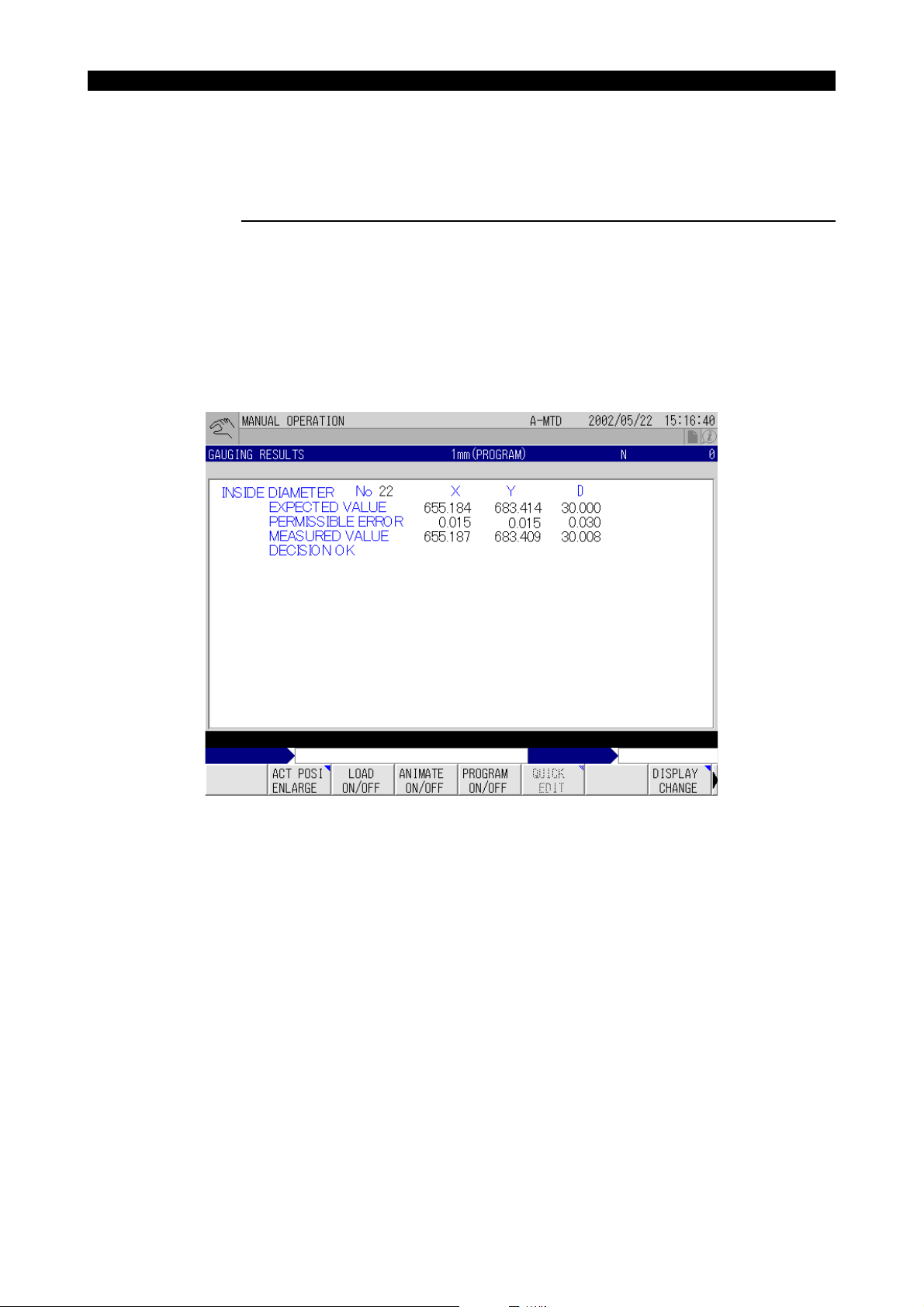
Display the screen that displays the gauging result (GAUGING RESULTS screen) by following the
steps indicated below.
Procedure :
1 Select an operation mode (automatic, MDI, manual).
2 Press function key [F8] (DISPLAY CHANGE).
The DISPLAY CHANGE window opens.
3 In the DISPLAY CHANGE window, select “GAUGING RESULTS”.
4 Press function key [F8] (CLOSE).
The GAUGING RESULTS screen, shown below, is displayed.
Eeoemr5s1004
EIOEMR5S1001R01
Page 14

SECTION 1 AUTOMATIC TOOL LENGTH OFFSET/AUTOMATIC TOOL BREAKAGE DETECTION
1-2. Function Menu
4297-E P-3
The function menu switches as shown below to display the functions relating to the gauging result
Eeoemr5s1005
when the extend key, to the right of function key [F8] (DISPLAY CHANGE), is pressed.
EIOEMR5S1002R01
When the extend key is pressed.
EIOEMR5S1003R01
The function menu relating to gauging result processing is described below.
Function Menu Description
TOOL/ZERO Displays the presently set zero offset/tool offset number.
MSB ZERO ON/OFF Displays the offset data presently set for the individual zero offset num-
bers.
MSB TOOL ON/OFF Displays the offset data presently set for the tool length offset number
and the cutter diameter offset number.
SENSstat ON/OFF Displays the value set for system variable VNCOM and the sensor con-
tact status.
VARIOUS ON/OFF Displays the values set for the system variables.
For details on the function keys, refer to [1-2-1. TOOL/ZERO Function Key] to [1-2-5. VARIOUS ON/
OFF Function Key].
Page 15

SECTION 1 AUTOMATIC TOOL LENGTH OFFSET/AUTOMATIC TOOL BREAKAGE DETECTION
1-2-1. TOOL/ZERO Function Key
4297-E P-4
The TOOL/ZERO pop-up window displays the presently set zero offset number and tool offset numbers. To display the TOOL/ZERO pop-up window, follow the procedure indicated below.
Procedure :
1 Display the GAUGING RESULTS screen.
For the procedure used to display the GAUGING RESULTS screen, refer to [1-1. Displaying the
Result of Gauging].
2 Press the extend key to switch the function menu.
3 Press function key [F2] (TOOL/ZERO).
The TOOL/ZERO pop-up window opens.
Eeoemr5s1006
EIOEMR5S1004R01
The TOOL/ZERO pop-up window closes when function key [F2] (TOOL/ZERO) is pressed
again.
Page 16
SECTION 1 AUTOMATIC TOOL LENGTH OFFSET/AUTOMATIC TOOL BREAKAGE DETECTION
1-2-2. MSB ZERO ON/OFF Function Key
4297-E P-5
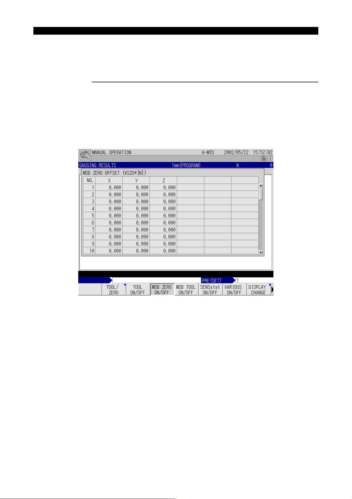
The MSB (VSZO✽[N]) pop-up window displays the offset data set for the individual zero offset numbers. To display the MSB (VSZO✽[N]) pop-up window, follow the procedure indicated below.
Procedure :
1 Display the GAUGING RESULTS screen.
For the procedure used to display the GAUGING RESULTS screen, refer to [1-1. Displaying the
Result of Gauging].
2 Press the extend key to switch the function menu.
3 Press function key [F4] (MSB ZERO ON/OFF).
The MSB (VSZO✽[N]) pop-up window opens.
Eeoemr5s1007
EIOEMR5S1005R01
The MSB (VSZO✽[N]) pop-up window closes when function key [F4] (MSB ZERO ON/OFF) is
pressed again.
Page 17
SECTION 1 AUTOMATIC TOOL LENGTH OFFSET/AUTOMATIC TOOL BREAKAGE DETECTION
1-2-3. MSB TOOL ON/OFF Function Key
4297-E P-6
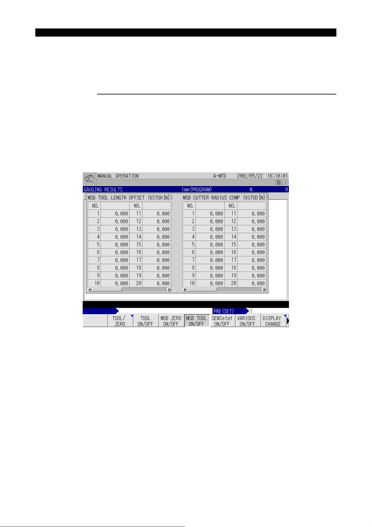
The TOOL OFFSET/COMPENSATION pop-up window displays the offset data set for the individual
tool length offset and cutter radius compensation numbers. To display the TOOL OFFSET/COMPENSATION pop-up window, follow the procedure indicated below.
Procedure :
1 Display the GAUGING RESULTS screen.
For the procedure used to display the GAUGING RESULTS screen, refer to [1-1. Displaying the
Result of Gauging].
2 Press the extend key to switch the function menu.
3 Press function key [F5] (MSB TOOL ON/OFF).
The MSB TOOL LENGTH OFFSET (VSTOH[N])/MSB CUTR RADIUS COMP (VSTOD[N])
pop-up window opens.
Eeoemr5s1008
EIOEMR5S1006R01
The MSB TOOL LENGTH OFFSET (VSTOH[N])/MSB CUTR RADIUS COMP (VSTOD[N])
pop-up window closes when function key [F5] (MSB TOOL ON/OFF) is pressed again.
Page 18
SECTION 1 AUTOMATIC TOOL LENGTH OFFSET/AUTOMATIC TOOL BREAKAGE DETECTION
1-2-4. SENSstat ON/OFF Function Key
4297-E P-7
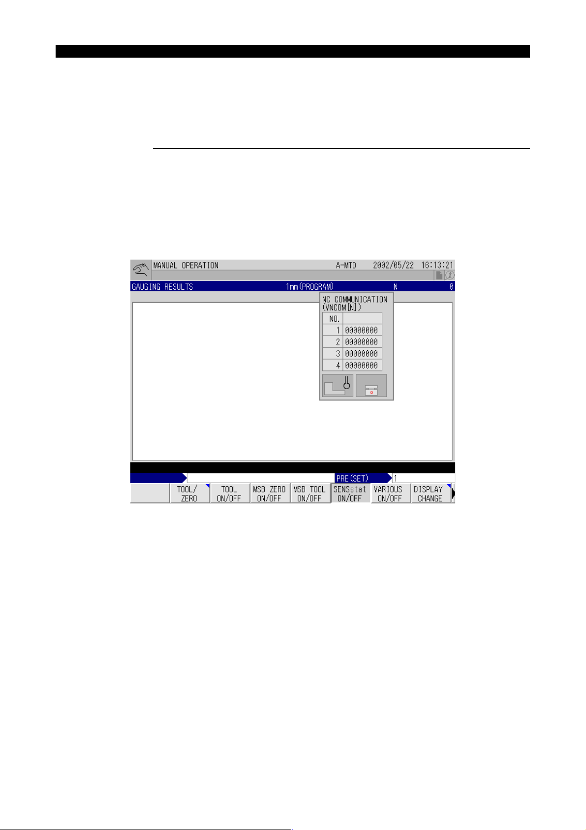
The NC COMMUNICATION (VNCOM[N]) pop-up window displays the values set for system variables VNCOM and the contact status of the sensor. To display the NC COMMUNICATION
(VNCOM[N]) pop-up window, follow the procedure indicated below.
Procedure :
1 Display the GAUGING RESULTS screen.
For the procedure used to display the GAUGING RESULTS screen, refer to [1-1. Displaying the
Result of Gauging].
2 Press the extend key to switch the function menu.
3 Press function key [F6] (SENSstat ON/OFF).
The NC COMMUNICATION (VNCOM[N]) pop-up window opens.
Eeoemr5s1009
EIOEMR5S1007R01
The NC COMMUNICATION (VNCOM[N]) pop-up window closes when function key [F6]
(SENSstat ON/OFF) is pressed again.
Page 19
SECTION 1 AUTOMATIC TOOL LENGTH OFFSET/AUTOMATIC TOOL BREAKAGE DETECTION
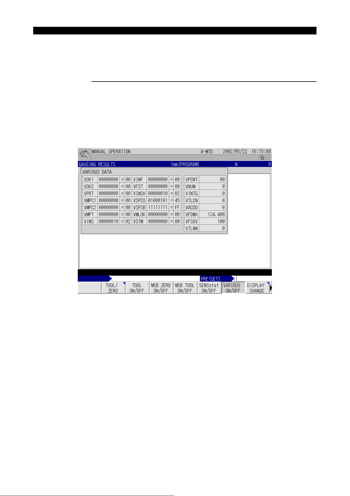
1-2-5. VARIOUS ON/OFF Function Key
4297-E P-8
The VARIOUS DATA pop-up window displays the values set for the individual system variables. To
display the VARIOUS DATA pop-up window, follow the procedure indicated below.
Procedure :
1 Display the GAUGING RESULTS screen.
For the procedure used to display the GAUGING RESULTS screen, refer to [1-1. Displaying the
Result of Gauging].
2 Press the extend key to switch the function menu.
3 Press function key [F7] (VARIOUS ON/OFF).
The VARIOUS DATA pop-up window opens.
Eeoemr5s1010
EIOEMR5S1010R01
The VARIOUS DATA pop-up window closes when function key [F7] (VARIOUS ON/OFF) is
pressed again.
Page 20
4297-E P-9
SECTION 1 AUTOMATIC TOOL LENGTH OFFSET/AUTOMATIC TOOL BREAKAGE DETECTION
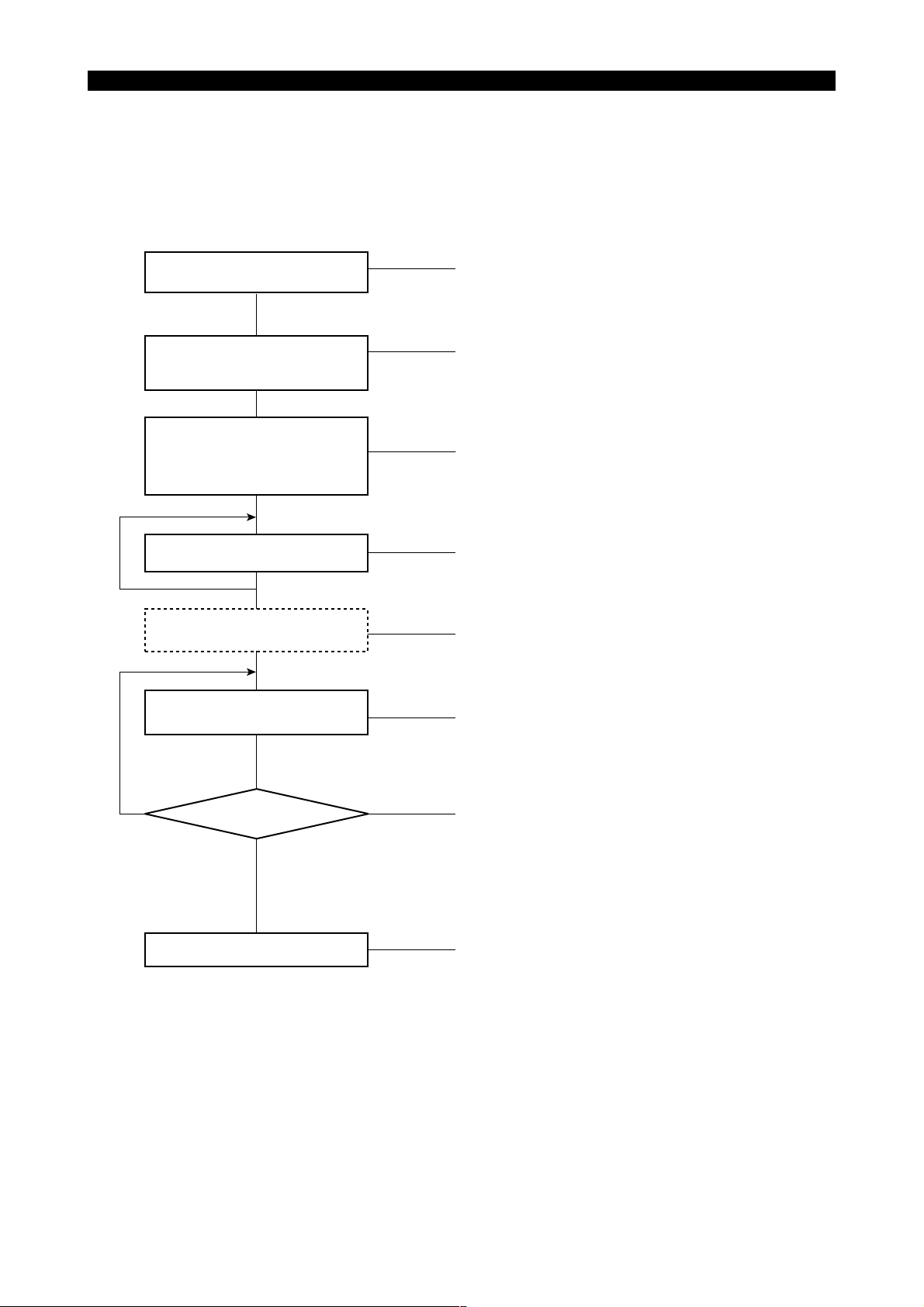
2. Automatic Tool Length Offset/Automatic Tool Breakage Detection Operation
A general breakdown of the operational procedure for carrying out automatic tool length and tool
breakage detection functions is given below.
Setting the zero point for the
touch sensor
Setting the correspondence
between pot numbers/tool
numbers
Executing the automatic tool
length offset cycle with the tool
used for setting the touch
sensor zero point
Executing automatic tool length
offset for other tools
Setting the tool change
position data
Zero point setting is necessary only when the
machine is installed.
(If higher gauging accuracy is required, however, you
are recommended to set the zero point occasionally.)
When tools in the magazine are replaced, it is necessary to set the new correspondence between the tool
pot numbers and the tool numbers.
Make sure that the tool length offset value is
"0±0.005 mm" or "PLI setting±0.005mm".
Call the tool whose tool length offset data is to be
set from the magazine and mount it in the spindle,
then execute the automatic tool length offset cycle.
Repeat this operation for all tools that require tool
length offset data setting.
This step is not necessary for MC-H.
Eeoemr5s1011
Tool not
broken
Usually, the tool breakage detection cycle is exe-
Executing automatic tool
breakage detection cycle
Checking for breakage
Tool broken
Pallet change, etc.
[Supplement]
With a double-column machining center that has a touch sensor at a location other than the crossrail (on the table, for example), the Z-axis zero point must be set after positioning the crossrail.
cuted after each cutting operation with the relevant
tool is completed.
Tool length offset data must be set for tools that are
checked for breakage.
The function determines whether the machining is
continued as programmed or error processing is executed according to the result of the automatic tool
breakage detection cycle.
This step is not necessary if the setting that specifies
the machine should stop in the alarm stop state when
tool breakage is detected is made.
When the setting that specifies automatic selection of
a spare tool if tool breakage is detected is made, the
error processing on occurrence of tool breakage
should be as follows: the CNC judges that the workpiece machined using the broken tool is defective,
changes the pallet to a new one and starts machining
for a new workpiece.
EIOEMR5S1009R01
Page 21
SECTION 1 AUTOMATIC TOOL LENGTH OFFSET/AUTOMATIC TOOL BREAKAGE DETECTION
2-1. Setting the Touch Sensor Zero Point
2-1-1. Setting the Touch Sensor Zero Point (Z-axis)
4297-E P-10
Set the Z-axis direction offset value of the touch sensor zero point using a reference tool so that the
automatic tool length offset/automatic tool breakage detection function operates correctly.
Eeoemr5s1012
NOTICE
If Y-axis has to be retracted to set the touch sensor zero point, set the Y-axis retraction position
first by referring to [4. Y-axis Escape Position (MCM-B/MCR-B II/MCR-A/VH-40)].
Procedure :
1 After selecting the MDI mode, input “VFST=✽✽”, press the CYCLE START button.
Set an appropriate value for "✽✽" by referring to [2-3. Operation Mode Designation]. In this setting, either the automatic tool length offset mode or the automatic tool breakage detection cycle
may be selected.
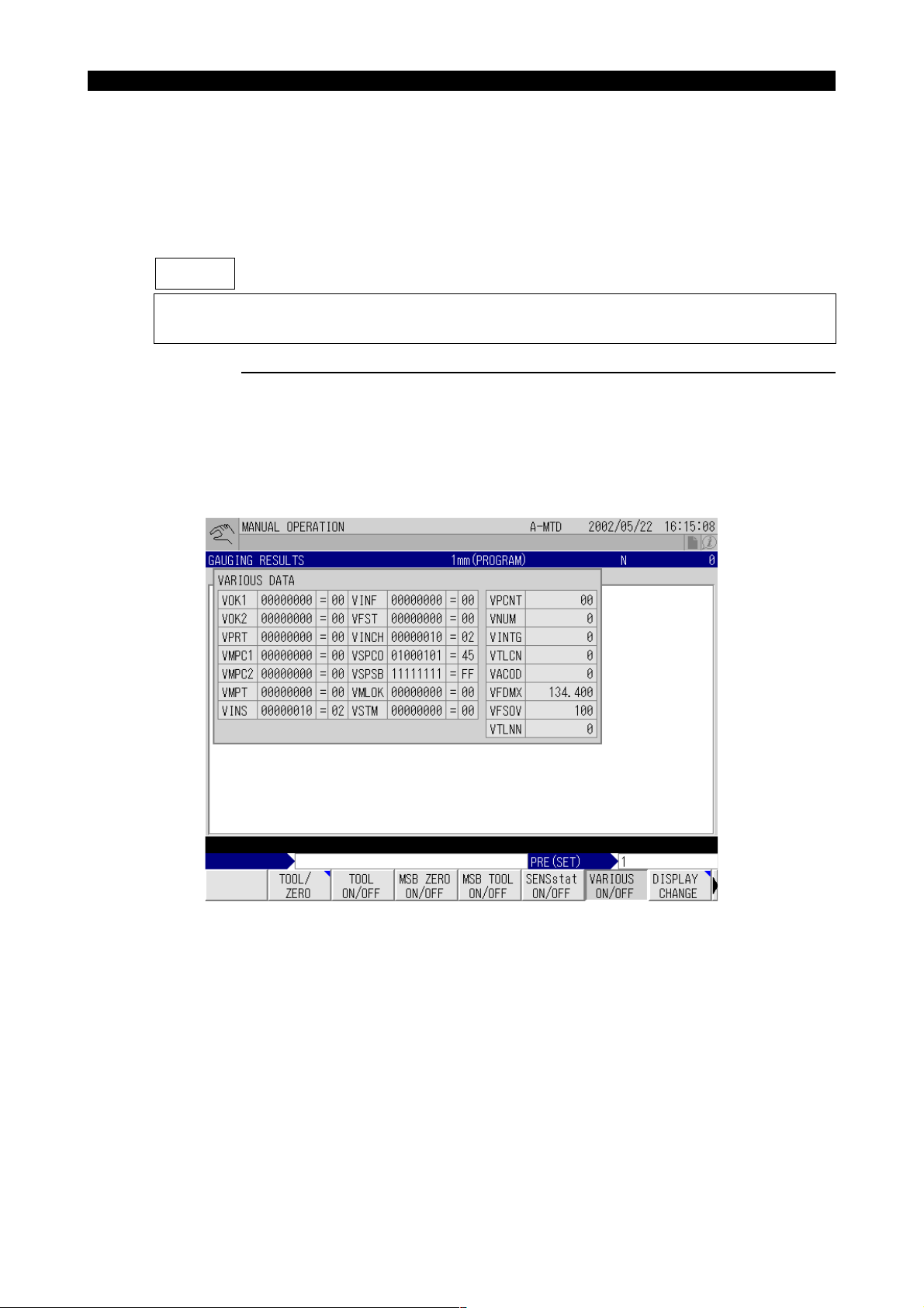
The set value can be confirmed by opening the VARIOUS DATA pop-up window on the GAUGING RESULTS screen.
EIOEMR5S1010R01
For the procedure for opening the VARIOUS DATA pop-up window, refer to [1-2-5. VARIOUS
ON/OFF Function Key].
2 Execute the sensor advance command M144 in the MDI mode. (In the case of a movable type
sensor)
3 Set the reference tool in the spindle, and manually bring the nose of the reference tool near the
Z-axis touch sensor.
There will inevitably be some slight displacement between the center of the sensor and the
center of the reference tool. This displacement, however, does not pose a problem for the succeeding operation.
Page 22

4297-E P-11
SECTION 1 AUTOMATIC TOOL LENGTH OFFSET/AUTOMATIC TOOL BREAKAGE DETECTION
[Supplement]
The “reference tool” means the tool used for setting the zero point in a work coordinate system.
4 At this position, execute the following program after selecting the automatic mode.
CALL OO30 PAXI=7 PLI=✽✽ (VFST=✽✽)
M02
[Supplement]
The settings for PLI should be as indicated below
Offset Type PLl Setting
Relative offset type 0
Absolute offset type Length from the spindle nose
face
Usually, the tool used for zero setting of the work coordinate system is also used for the sensor
zero point setting cycle. Therefore, there is no tool length difference between the tools used for
the two different zero point setting cycles, and the setting for PLI should be “zero” (PLI = 0).
For the absolute offset type, set the accurate length of the tool currently set in the spindle as
illustrated to the left.
If no value is set for PLI, either “PLI = 150 mm.” or “PLI = 200 mm” is assumed. Which of the
values is used is determined by the machine model.
Relative offset type
PLI = 0
Absolute offset type
PLI
EIOEMR5S1011R01
[Supplement]
VFST may be set in this step instead of setting it first in the MDI mode.
As the program above is executed, the reference tool automatically comes into contact with
the Z-axis touch sensor, whereupon Z-axis zero offset is executed.
Zero offset of both the X and Y axes is executed so that the present (actual) position of the reference tool becomes X = 0, Y = 0.
How the reference tool moves during the execution of the program is explained in [2-1-2. Reference Tool Movements during Z-axis Touch Sensor Zero Point Setting].
Page 23
4297-E P-12
SECTION 1 AUTOMATIC TOOL LENGTH OFFSET/AUTOMATIC TOOL BREAKAGE DETECTION
5 Execute the sensor advance command M144 in the MDI mode. (In the case of a movable type
sensor)
6 Mount a small-diameter drill in the spindle.
7 Bring the drill tip manually near to the touch sensor and align the spindle center (drill center)
with the center of the touch sensor.
8 At this position, execute the following program after selecting the automatic mode.
CALL OO30 PAXI=3
M02
X- and Y-axis zero offset is executed so that the present (actual) position of the drill becomes X
= 0, Y = 0. (The Z-axis does not move.)
After the execution of the X- and Y-axis zero offset, the Z-axis moves at a rapid feedrate to the
travel end in the positive (+) direction and the sensor retracts, completing touch sensor zero
point setting.
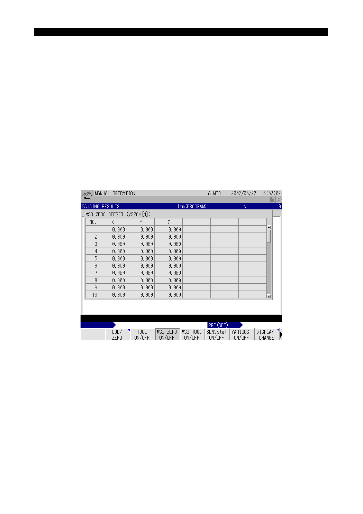
The result is fed back to the offset data of system work coordinate system No. 1.
The set offset data can be checked by opening the MSB ZERO OFFSET (VSZO✽[N]) pop-up
window on the GAUGING RESULTS screen. The offset data of the X-, Y- and Z-axis is displayed at the X, Y, and Z columns of the NO. 1 line
EIOEMR5S1012R01
[Supplement]
Since system work coordinate system No. 1 is used exclusively for the automatic tool length
offset and automatic tool breakage detection functions, it cannot normally be set or referenced.
For the procedure for opening the MSB ZERO OFFSET (VSZO✽[N]) pop-up window, refer to
[1-2-2. MSB ZERO ON/OFF Function Key].
This completes the Z-axis touch sensor zero point setting.
Page 24

4297-E P-13
SECTION 1 AUTOMATIC TOOL LENGTH OFFSET/AUTOMATIC TOOL BREAKAGE DETECTION
2-1-2. Reference Tool Movements during Z-axis Touch Sensor Zero Point Setting
During the execution of the Z-axis touch sensor zero point setting, the reference tool moves as indicated below.
Machine operation
(1) The Z-axis moves at a rapid feedrate to the travel end in the positive (+) direction.
(2) The spindle is oriented.
(3) If the movable type sensor is used, the sensor moves back once and then moves forward.
(4) The Z-axis moves at an approach feedrate in the negative (-) direction until the reference tool
comes into contact with the touch sensor.
(5) The Z-axis comes to a stop when the reference tool comes into contact with the touch sensor.
(6) The Z-axis moves at a rapid feedrate to the travel end in the positive (+) direction.
(7) If the movable type sensor is used, the sensor moves back.
2-1-3. Setting the Touch Sensor Zero Point (Y-axis)
When the specifications for automatic tool length offset and automatic breakage detection in the Yaxis direction (diameter direction) are selected, set the Y-axis touch sensor zero point retraction
position first by referring to [2-4. Automatic Tool Length Offset Function].
Procedure :
Eeoemr5s1013
Eeoemr5s1014
1 After selecting the MDI mode, input “VFST=✽✽”, and press the CYCLE START button.
Set an appropriate value for "✽✽" by referring to [2-3. Operation Mode Designation]. In this setting, either the automatic tool length offset mode or the automatic tool breakage detection cycle
may be selected.
If an appropriate value is already set for VFST, it is not necessary to set the value here.
The set value can be confirmed by opening the VARIOUS DATA pop-up window on the GAUGING RESULTS screen. For the procedure for opening the VARIOUS DATA pop-up window,
refer to [1-2-5. VARIOUS ON/OFF Function Key].
2 Execute the sensor advance command M144 in the MDI mode. (In the case of a movable type
sensor)
3 Set the reference tool in the spindle, and manually bring the nose of the reference tool near the
Y-axis touch sensor.
Align the center of the reference tool with the center of the Y-axis touch sensor.
4 At this position, execute the following program after selecting the automatic mode.
CALL OO30 PAXI=#17H PLI=0(or accurate length of reference tool)
PY=Accurate radius of reference tool (VFST=**)
M02
EIOEMR5S1013R01
In actual programming, the three lines of program above are expressed in one line as indicated
below.
Page 25

4297-E P-14
SECTION 1 AUTOMATIC TOOL LENGTH OFFSET/AUTOMATIC TOOL BREAKAGE DETECTION
[Example]
CALL OO30 PAXI=#17H PLI=0 PY=10 (VFST=1)
φ or accurate length of reference tool Accurate radius of reference tool
EIOEMR5S1014R01
[Supplement]
1) When setting PLI, pay attention to the same point as explained in [2-1-1. Setting the Touch Sen-
sor Zero Point (Z-axis)].
2) Always set PY. If it is not set, “PY = 0” is assumed.
3) VFST may be set in this step instead of setting it first in the MDI mode.
As the program above is executed, the reference tool automatically comes into contact with the
Y-axis touch sensor, whereupon Y-axis zero offset is executed. Zero offset of both the Z and X
axes is executed at the same time.
How the reference tool moves during the execution of the program is explained in [2-1-4. Reference Tool Movements during Y-axis Touch Sensor Zero Point Setting].
The result is fed back to the offset data of system work coordinate system No. 4.
The set offset data can be checked by opening the MSB ZERO OFFSET (VSZO✽[N]) pop-up
window on the GAUGING RESULTS screen. The offset data of the X-, Y- and Z-axis is displayed at the X, Y, and Z columns, respectively.
[Supplement]
Since system work coordinate system No. 4 is used exclusively for the automatic tool length offset
and automatic tool breakage detection functions, it cannot normally be set nor referenced.
For the procedure for opening the MSB ZERO OFFSET (VSZO✽[N]) pop-up window, refer to [1-2-2.
MSB ZERO ON/OFF Function Key].
This completes the Y-axis touch sensor zero point setting.
2-1-4. Reference Tool Movements during Y-axis Touch Sensor Zero Point Setting
During the execution of the Y-axis touch sensor zero point setting, the reference tool moves as indicated below.
Machine operation
(1) The Z-axis moves at a rapid feedrate to the travel end in the positive (+) direction.
(2) The spindle is oriented.
(3) If the movable type sensor is used, the sensor moves back once and then moves forward.
(4) The Z-axis moves to the Y-axis touch sensor position (the position where the Z-axis was first
moved manually).
(5) The Y-axis moves at an approach feedrate until the reference tool comes into contact with the
touch sensor.
(6) The Y-axis comes to a stop when the reference tool comes into contact with the touch sensor.
Eeoemr5s1015
(7) The Y-axis moves at a rapid feedrate to the approach start position.
(8) The Z-axis moves at a rapid feedrate to the travel end in the positive (+) direction.
(9) If the movable type sensor is used, the sensor moves back.
Page 26

SECTION 1 AUTOMATIC TOOL LENGTH OFFSET/AUTOMATIC TOOL BREAKAGE DETECTION
2-2. Setting the Tool Pot No./Tool No. Table
4297-E P-15
Set the correspondence between tool numbers and tool pot numbers in the tool pot number - tool
number correspondence table.
The table setting shown below uses a machine with 10-tool capacity magazine as an example.
Magazine capacity: 10 tools
Eeoemr5s1016
Assign a tool number
to each tool.
The total number of tools user for cutting
the various types of workpieces is 300.
Correspondence Table
Toolpot Number
1
2
3
4
5
6
7
8
9
10
Tool Number
1
2
3
20
30
31
32
105
270
271
Write the correspondence between the
tool number and the pot number on the
screen when tools in the magazine are
to be changed for new setup.
The memory of the OSP can hold the life
expectancy data of up to 300 tools.
Max. tool number:
Standard 50
Option 300
EIOEMR5S1015R01
The tool offset data obtained by the execution of an automatic tool length offset cycle is set for the
same offset number as the tool number of the tool presently being used (active tool).Similarly, the
tool offset number referred to and compared when the automatic tool breakage detection cycle is
executed is the same offset number as the tool number of the active tool.
[Supplement]
To automatically change a tool for a spare tool, tools must be registered in a tool group.
For the procedure for registering tools in a group, refer to the Tool Management Function section of
the special specifications of the Operation Manual.
Page 27

SECTION 1 AUTOMATIC TOOL LENGTH OFFSET/AUTOMATIC TOOL BREAKAGE DETECTION
2-3. Operation Mode Designation
4297-E P-16
The basic operation mode of automatic tool length offset and automatic tool breakage detection is
designated by the system variable VFST.
Since the system variable VFST is backed up in the CNC memory, it only has to be designated
once: it does not have to be set each time the MSB of the automatic tool length offset/automatic tool
breakage detection cycle is called.
VFST consists of one byte (8 bits) and each bit has the following significance.
VFST
Bit 7 Bit 6 Bit 5 Bit 4 Bit 3 Bit 2 Bit 1 Bit 0
Bit No Setting Description
Bit 0
Bit 1 1
Bit 2 1
Bit 3 1
Bit 4 0 Always set “0”.
Bit 5 0 Always set “0”.
Bit 6 0 Always set “0”.
Bit 7
0 Automatic tool breakage detection cycle
1 Automatic tool length offset cycle
Executes the automatic tool length offset/automatic tool breakage detection cycle in the Y-axis direction.
Executes the automatic tool length offset/automatic tool breakage detection cycle in the Y-axis direction after the execution of the automatic tool
length offset/automatic tool breakage detection cycle in the Z-axis direction.
To execute automatic tool length offset/automatic tool breakage detection cycle only in the Z-axis direction, set “0” for both Bit 1 and Bit 2.
Does not move the X-axis when positioning a reference tool at the touch
sensor position.
Set “1” for Bit 3 with machine models such as MCV in which the touch
sensor is installed independently of the X-axis movement.
Designates the relative offset type.
0
1
The tool length in reference to the reference tool used for zero point setting of a work coordinate system is used as the tool length offset data.
Designates the absolute offset type.
The length of the tool from the spindle nose surface is regarded as the
tool length offset data.
Eeoemr5s1017
EIOEMR5S1016R01
Page 28

4297-E P-17
SECTION 1 AUTOMATIC TOOL LENGTH OFFSET/AUTOMATIC TOOL BREAKAGE DETECTION
An example of VFST settings is given in the following table.
Model
MC-H
MC-V
MCV
MCR
MCM
(Vertical
spindle)
Relative/
Absolute
Offset Type
Relative
offset
Absolute
offset
Relative
offset
Absolute
offset
X-axis
Movement
Yes/No
Yes Only Z-axis offset
Yes Only Z-axis offset
No
No
Z-axis/Y-axis Offset
Only Z-axis offset
Only Y-axis offset
Y-axis offset after Z-
axis offset
Only Z-axis offset
Only Y-axis offset
Y-axis offset after Z-
axis offset
Automatic Tool Length Off-
set/Automatic Tool Break-
age Detection
Automatic tool length offset #01H
Automatic tool breakage
detection
Automatic tool length offset #81H
Automatic tool breakage
detection
Automatic tool length offset #09H
Automatic tool breakage
detection
Automatic tool length offset #0BH
Automatic tool breakage
detection
Automatic tool length offset #0DH
Automatic tool breakage
detection
Automatic tool length offset #89H
Automatic tool breakage
detection
Automatic tool length offset #8BH
Automatic tool breakage
detection
Automatic tool length offset #8DH
Automatic tool breakage
detection
VFST
Value
#00H
#80H
#08H
#0AH
#0CH
#88H
#8AH
#8CH
[Supplement]
Refer to [3-1. Automatic Tool Length Offset/Automatic Tool Breakage Detection Function for Horizontal Tools of MCM] for details of automatic tool length offset/automatic tool breakage detection
for the horizontal tools of MCM horizontal.
Page 29

SECTION 1 AUTOMATIC TOOL LENGTH OFFSET/AUTOMATIC TOOL BREAKAGE DETECTION
2-4. Automatic Tool Length Offset Function
4297-E P-18
The automatic tool length offset function automatically corrects the tool length according to the offset data set using the reference tool.
2-4-1. Z-axis Automatic Tool Length Offset
Automatic tool length offset in the Z-axis direction is executed in the manner indicated below.
NOTICE
Make sure that the zero point of the Z-axis touch sensor has been set before executing Z-axis
automatic tool length offset. Never execute Z-axis automatic tool length offset when the Z-axis
touch sensor zero point has not been set.
Procedure :
1 After selecting the MDI mode, input “VFST=✽✽”, and press the CYCLE START button.
Set an appropriate value for "✽✽" by referring to [2-3. Operation Mode Designation].
The set value can be confirmed by opening the VARIOUS DATA pop-up window on the GAUGING RESULTS screen. Refer to [1-2-5. VARIOUS ON/OFF Function Key].
2 Mount the tool for which automatic tool length offset is to be executed in the spindle.
When the tool is mounted in the spindle manually, make sure that the active tool number displayed on the ATC TOOL DISPLAY (MEMORY RANDOM) screen (for the ATC memory random
specification) or the POT NO./TOOL NO. TABLE (FIXED ADDRESS) screen (for the ATC fixed
address specification) agrees with the tool number of the tool mounted in the spindle.
This operation is not necessary when the tool is mounted in the spindle by executing the M06
command, either in automatic or MDI operation.
Eeoemr5s1018
Eeoemr5s1019
3 Execute the following program after selecting the automatic mode.
CALL OO30 (VFST=✽✽) (PLI = Anticipated tool length)
M02
When the program is executed, the tool is automatically brought into contact with the Z-axis
touch sensor and the tool length offset data is calculated and stored in the CNC memory.
The set tool length offset data can be checked by displaying the TOOL LENGTH OFFSET/
CUTTER RADIUS COMPENSATION screen of the TOOL DATA screen.
Page 30

4297-E P-19
SECTION 1 AUTOMATIC TOOL LENGTH OFFSET/AUTOMATIC TOOL BREAKAGE DETECTION
The obtained results are also displayed on the GAUGING RESULTS screen
EIOEMR5S1017R01
This ends the Z-axis automatic tool length offset processing.
[Supplement]
1) VFST may be set in this step instead of setting it first in the MDI mode.
2) Set the anticipated tool length for PLI.
If no value is set for PLI, the value set for CNC optional parameter (long word) No. 43 (distance
from the spindle gauge line) is automatically set as the anticipated tool length.
Machine operation
During the execution of the Z-axis automatic tool length offset, the tool moves as indicated below.
(1) The Z-axis moves at a rapid feedrate to the travel end in the positive (+) direction.
(2) The spindle is oriented.
(3) The X- and Y-axis move at a rapid feedrate to align the tool nose with the center of the touch
sensor.
For tools whose nose is not at the center of the spindle, refer to items (6) PX and (7) PY in [6-3.
Explanation of Variables].
(4) The Z-axis moves at a fast approach feedrate until the tool comes into contact with the touch
sensor.
(5) The Z-axis comes to a stop when the reference tool comes into contact with the touch sensor.
(6) The Z-axis moves back several millimeters at a rapid feedrate.
(7) The Z-axis moves at an approach feedrate until the tool comes into contact with the touch sen-
sor again.
(8) The Z-axis comes to a stop when the reference tool comes into contact with the touch sensor.
The result of gauging is stored under the same tool length offset number as the tool number of
the active tool.
(9) The Z-axis moves at a rapid feedrate to the travel end in the positive (+) direction.
Page 31

SECTION 1 AUTOMATIC TOOL LENGTH OFFSET/AUTOMATIC TOOL BREAKAGE DETECTION
2-4-2. Y-axis Automatic Tool Length Offset
4297-E P-20
Automatic tool length offset in the Z-axis direction is executed in the manner indicated below.
Eeoemr5s1021
NOTICE
1) Make sure that the zero point of the Z-axis and Y-axis touch sensors has been set before executing Y-axis automatic tool length offset. Never execute Y-axis automatic tool length offset
when the touch sensor zero point has not been set.
2) Before executing automatic tool length offset in the Y-axis direction, set the Z-axis tool length
offset data of the tools.
The Z-axis tool length offset data can be set either by executing the Z-axis automatic tool
length offset or by inputting an appropriate value at the TOOL DATA screen.
Procedure :
1 After selecting the MDI mode, input “VFST=✽✽”, and press the CYCLE START button.
Set an appropriate value for "✽✽" by referring to [2-3. Operation Mode Designation].
The set value can be confirmed by opening the VARIOUS DATA pop-up window on the GAUGING RESULTS screen. Refer to [1-2-5. VARIOUS ON/OFF Function Key].
2 Mount the tool for which Y-axis automatic tool length offset is to be executed in the spindle.
When the tool is mounted in the spindle manually, make sure that the active tool number displayed on the ATC TOOL DISPLAY (MEMORY RANDOM) screen (for the ATC memory random
specification) or the POT NO./TOOL NO. TABLE (FIXED ADDRESS) screen (for the ATC fixed
address specification) agrees with the tool number of spindle mounted tool.
This operation is not necessary when the tool is mounted in the spindle by executing the M06
command either in automatic or MDI operation.
3 Execute the following program after selecting the automatic mode.
CALL OO30 PY= Anticipated cutter radius(VFST=✽✽)
M02
When the program is executed, the tool is automatically brought into contact with the Y-axis
touch sensor and the cutter radius compensation data is calculated and stored in the CNC
memory.
The set cutter radius compensation data can be checked by displaying the TOOL LENGTH
OFFSET/CUTTER RADIUS COMPENSATION screen of the TOOL DATA screen. The
obtained results are also displayed at the GAUGING RESULTS screen.
This ends the Y-axis automatic tool length offset processing.
[Supplement]
VFST may be set in this step instead of setting it first in the MDI mode.
Page 32

SECTION 1 AUTOMATIC TOOL LENGTH OFFSET/AUTOMATIC TOOL BREAKAGE DETECTION
Machine operation
During the execution of the Y-axis automatic tool length offset, the tool moves as indicated below.
(1) The Z-axis moves at a rapid feedrate to the travel end in the positive (+) direction.
(2) The spindle is oriented.
(3) The X- and Y-axis move at a rapid feedrate to align the tool nose with the center of the Z-axis
touch sensor.
(4) The Z-axis moves at a fast approach feedrate to align the tool nose with the center of the Y-axis
touch sensor.
(5) The Y-axis moves at an approach feedrate until the tool comes into contact with the Y-axis touch
sensor.
(6) The Y-axis comes to a stop when the tool comes into contact with the touch sensor.
The result of gauging is stored under the same cutter radius compensation number as the tool
number of the active tool.
(7) The Y-axis returns at a rapid feedrate.
(8) The Z-axis moves at a rapid feedrate to the travel end in the positive (+) direction.
2-4-3. Continuous Z-axis and Y-axis Automatic Tool Length Offset
4297-E P-21
To execute automatic tool length offset on the Z-axis and the Y-axis continuously, follow the procedure indicated below.
For points of caution and details of the tool length offset, refer to [2-4-1. Z-axis Automatic Tool
Length Offset] and [2-4-2. Y-axis Automatic Tool Length Offset].
Procedure :
1 After selecting the MDI mode, input “VFST=✽✽”, and press the CYCLE START button.
2 Execute the following program after selecting the automatic mode.
CALL OO30 PY= Anticipated cutter radius (PLI = Anticipated tool length) (VFST=✽✽)
M02
The tool is first brought into contact with the Z-axis touch sensor then the Y-axis touch sensor.
This ends the continuous Z-axis and Y-axis automatic tool length offset processing.
Eeoemr5s1023
Page 33

SECTION 1 AUTOMATIC TOOL LENGTH OFFSET/AUTOMATIC TOOL BREAKAGE DETECTION
2-5. Setting the Tool Change Position (Other Than MC-H)
4297-E P-22
When a tool is found to be broken in the automatic tool breakage detection cycle, the broken tool
can be automatically returned to the magazine by using a subprogram.
In order to execute this automatic tool return cycle, the tool change position must be set for MC-V
and double-column machining centers since these types of machining centers do not have a preset
ATC home position like MC-H.
If the tool change position is not set for these types of machining centers, the tool change will be carried out just above the touch sensor. Since this may cause problems with some kinds of workpieces, it is necessary to set the tool change position for MC-V and double-column machining
centers.
Procedure :
1 Move the spindle to the desired tool change position.
Note that X- and Y-axis must be positioned at the desired tool change position. Positioning of
the Z-axis is not necessary.
2 At this position, execute the following program after selecting the automatic mode.
CALL OO31
M02
The axes will not move at all even when a program is executed.
The set tool change position data can be checked by opening the MSB ZERO OFFSET
(VSZO✽[N]) pop-up window on the GAUGING RESULTS screen. The tool change position
data of the X-, Y- and Z-axis is displayed at the X, Y, and Z columns of the NO. 2 line.
This completes the tool change position setting.
Eeoemr5s1024
[Supplement]
Since system work coordinate system No. 2 is used exclusively for the automatic tool length offset
and automatic tool breakage detection functions, it cannot normally be set or referenced.
Page 34

SECTION 1 AUTOMATIC TOOL LENGTH OFFSET/AUTOMATIC TOOL BREAKAGE DETECTION
2-6. Automatic Tool Breakage Detection
2-6-1. Z-axis Automatic Tool Breakage Detection
4297-E P-23
Automatic tool breakage detection in the Z-axis direction is executed in the manner indicated below.
Eeoemr5s1025
NOTICE
Before executing Z-axis automatic tool breakage detection, make sure that the zero point of the
touch sensor and the tool change position have been set.
Procedure :
1 After selecting the MDI mode, input “VFST=✽✽”, and press the CYCLE START button.
Set an appropriate value for "✽✽" by referring to [2-3. Operation Mode Designation].
2 Mount the tool for which automatic tool breakage detection is to be executed in the spindle.
When the tool is mounted in the spindle manually, make sure that the active tool number displayed on the ATC TOOL DISPLAY (MEMORY RANDOM) screen (for the ATC memory random
specification) or the POT NO./TOOL NO. TABLE (FIXED ADDRESS) screen (for the ATC fixed
address specification) agrees with the tool number of the tool mounted in the spindle.
This operation is not necessary when the tool is mounted in the spindle by executing the M06
command either in automatic or MDI operation.
3 Execute the following program after selecting the automatic mode.
CALL OO30 PLE1 PLE1= Tool breakage judgment value (PGO=✽✽)
M02
When the program is executed, the tool is automatically brought into contact with the touch
sensor and the tool length is obtained.
The obtained tool length is compared to the tool length offset data stored in the CNC memory
and a tool breakage alarm occurs if the difference is greater than the value set for PLE1.
The tool breakage alarm also occurs if the tool nose fails to contact the touch sensor during the
execution of the program.
This ends the Z-axis automatic tool breakage detection processing.
[Supplement]
1) VFST may be set in this step instead of setting it first in the MDI mode.
2) To replace a broken tool with a spare tool, PGO must be designated.
For details of PGO, refer to item (11) PGO(P GO) in [6-3. How to Use Variables].
Page 35

4297-E P-24
SECTION 1 AUTOMATIC TOOL LENGTH OFFSET/AUTOMATIC TOOL BREAKAGE DETECTION
Machine operation
During the execution of the Z-axis automatic tool breakage detection, the tool moves as indicated
below.
(1) The Z-axis moves at a rapid feedrate to the travel end in the positive (+) direction.
(2) The spindle is oriented.
(3) The X- and Y-axis move at a rapid feedrate to align the tool nose with the center of the Z-axis
touch sensor.
For tools whose nose is not at the center of the spindle, refer to items (6) PX and (7) PY in [6-3.
Explanation of Variables].
(4) The Z-axis moves at a fast approach feedrate until the tool nose reaches the position 20 mm
away from the touch sensor.
(5) The Z-axis moves at an approach feedrate to the position 10 mm past the point where the tool
nose would be in contact with the touch sensor.
• If the tool has not been broken or the amount of chipping is smaller than 10 mm:
The tool nose comes into contact with the touch sensor and the Z-axis stops. The tool
length is calculated from the coordinate value of the contact position and is stored in the
CNC memory temporarily.
• If the tool has been broken (amount of chipping is greater than 10 mm):
The tool nose will not contact the touch sensor.
(6) The Z-axis moves at a rapid feedrate to the travel end in the positive (+) direction.
Page 36

SECTION 1 AUTOMATIC TOOL LENGTH OFFSET/AUTOMATIC TOOL BREAKAGE DETECTION
2-6-2. Y-axis Automatic Tool Breakage Detection
4297-E P-25
Automatic tool breakage detection in the Y-axis direction is executed in the manner indicated below.
Eeoemr5s1027
NOTICE
Before executing Z-axis automatic tool breakage detection, make sure that the zero point of the
touch sensor has been set.
Procedure :
1 After selecting the MDI mode, input “VFST=✽✽”, and press the CYCLE START button.
Set an appropriate value for "✽✽" by referring to [2-3. Operation Mode Designation].
2 Mount the tool for which automatic tool breakage detection is to be executed in the spindle.
When the tool is mounted to the spindle manually, make sure that the active tool number displayed on the ATC TOOL DISPLAY (MEMORY RANDOM) screen (for the ATC memory random
specification) or the POT NO./TOOL NO. TABLE (FIXED ADDRESS) screen (for the ATC fixed
address specification) agrees with the tool number of the tool mounted in the spindle.
This operation is not necessary when the tool is mounted in the spindle by executing the M06
command either in automatic or MDI operation.
3 Execute the following program after selecting the automatic mode.
CALL OO30 PLEY=Tool breakage judgment value PY=Anticipated cutter radius (VFST=✽✽)
M02
When the program is executed, the tool is automatically brought into contact with the touch
sensor and the cutter radius is obtained.
The obtained cutter radius is compared to the cutter radius compensation data stored in the
CNC memory and a tool breakage alarm occurs if the difference is greater than the value set
for PLEY.
The tool breakage alarm also occurs if the tool fails to contact the touch sensor during the execution of the program.
This ends the Y-axis automatic tool breakage detection processing.
[Supplement]
1) VFST may be set in this step instead of setting it first in the MDI mode.
2) To replace a broken tool with a spare tool, PGO must be designated.
Page 37

4297-E P-26
SECTION 1 AUTOMATIC TOOL LENGTH OFFSET/AUTOMATIC TOOL BREAKAGE DETECTION
Machine operation
During the execution of the Y-axis automatic tool breakage detection, the tool moves as indicated
below.
(1) The Z-axis moves at a rapid feedrate to the travel end in the positive (+) direction.
(2) The spindle is oriented.
(3) The X- and Y-axis move at a rapid feedrate to align the tool nose with the center of the touch
sensor.
(4) The Z-axis moves at a rapid feedrate to align the tool nose with the center of the Y-axis touch
sensor.
(5) The Y-axis moves at an approach feedrate to the position 10 mm past the point where the tool
nose would be in contact with the touch sensor.
• If the tool has not been broken or amount of chipping is smaller than 10 mm:
The tool nose comes into contact with the touch sensor and the Y-axis stops. The cutter
radius is calculated from the coordinate value of the contact position and is stored in the
CNC memory temporarily.
• If the tool has been broken (amount of chipping is greater than 10 mm):
The tool nose will not contact the touch sensor.
(6) The Y-axis returns at a rapid feedrate.
(7) The Z-axis moves at a rapid feedrate to the travel end in the positive (+) direction.
2-6-3. Continuous Z-axis and Y-axis Automatic Tool Breakage Detection
To execute automatic tool breakage detection on the Z-axis and the Y-axis continuously, follow the
procedure indicated below.
For items carefully attended to and details of the tool length offset, refer to [2-6-1. Z-axis Automatic
Tool Breakage Detection] and [2-6-2. Y-axis Automatic Tool Breakage Detection].
Procedure :
1 After selecting the MDI mode, input “VFST=✽✽” and press the CYCLE START button.
2 Execute the following program after selecting the automatic mode.
CALL OO30 (VFST=**) PY=Anticipated cutter radius
PLE1=Tool breakage judgment value (Z-axis)
PLEY=Tool breakage judgment value (Y-axis)
M02
3 The tool is first brought into contact with the Z-axis touch sensor to check tool breakage in the
Z-axis direction. When tool breakage is not detected in the Z-axis direction, tool breakage in
the Y-axis direction is checked.
Eeoemr5s1028
EIOEMR5S1018R01
Page 38

SECTION 1 AUTOMATIC TOOL LENGTH OFFSET/AUTOMATIC TOOL BREAKAGE DETECTION
2-6-4. Judgment of Tool Breakage
4297-E P-27
When a spare tool is selected in response to the detection of tool breakage, operation does not stop
even when the breakage is detected. Therefore, it is necessary to judge the occurrence of tool
breakage at the end of the automatic tool breakage detection cycle and branch the program execution in accordance with the result of the judgement.
• It can be judged whether or not the tool is broken by reading system variable VOK1.
VOK1 = 0 Tool is not broken.
VOK1 ≠ 0 Tool is broken.
VOK1 indicates the result of the previously executed automatic tool breakage detection cycle.
• Another system variable VOK2 is also available for judgement.
VOK2 indicates the result of automatic tool breakage detection cycles executed after clearance
to 0 (VOK2 = 0). If tool breakage is detected even once, the value set for VOK2 is “VOK2 ≠ 0”.
• VOK1 and VOK2 are not cleared to 0 when the CNC is reset.
[Supplement]
When tool breakage is detected by the automatic tool breakage detection function, the tool number
is registered by the tool management function as that of a broken tool.
In order to use the same tool number after taking the necessary measures, such as replacement
with a new tool, the registration of the broken tool number must be cleared.
Refer to Tool Management Function in special specifications of the Operation Manual for the procedure for resetting broken tool registration.
Eeoemr5s1029
Page 39

4297-E P-28
SECTION 1 AUTOMATIC TOOL LENGTH OFFSET/AUTOMATIC TOOL BREAKAGE DETECTION
2-7. Cycle Time Reduction for Automatic Tool Length Offset/Automatic
Tool Breakage Detection Cycle
By feeding a tool close to the sensor at a rapid feedrate, it is possible to reduce the cycle time of the
automatic tool length offset/automatic tool breakage detection cycle.
Spindle nose face
Tool
G0 (4)
G31F=PF1
G31F2000
To use this function, it is necessary to set the following parameters.
• Optional parameter (bit) No. 36, bit 3:
Default of maximum tool length for automatic tool length offset/tool breakage detection
With check mark: Valid
Without check mark: Invalid (Initial value)
(5)
(6)
Safety distancePUDT
Sensor
Fig.1-1 Cycle Time Reduction Function
Max.
tool
length
VLTL
Anticipatedtool
length
PL1
Eeoemr5s1031
EIOEMR5S1019R01
• Optional parameter (long ward) No. 44: Max. tool length
For this parameter, set the maximum tool length among the tools that will be used.
Setting range: 0 to 999
Unit: mm
Initial setting: 0
CAUTION
Set an appropriate value for the maximum tool length setting parameter since “0” is set as
the initial value.
Page 40

SECTION 1 AUTOMATIC TOOL LENGTH OFFSET/AUTOMATIC TOOL BREAKAGE DETECTION
2-7-1. Automatic tool length offset cycle
4297-E P-29
Machine operation
(1) The Z-axis moves at a rapid feedrate to the travel end in the positive (+) direction.
(2) The spindle is oriented.
(3) The X- and Y-axis move at a rapid feedrate to align the tool nose with the center of the touch
sensor.
(4) The Z-axis moves at a rapid feedrate to the point distanced from the touch sensor by “safety dis-
tance (PUDT) + max. tool length (VLTL)”.
This operation is or is not executed according to the setting for the parameter.
(5) The Z-axis moves at a skip feedrate, specified by PF1, to the point distanced from the touch
sensor by “anticipated tool length (PLI) + safety distance (PUDT)”.
If the PLI command is not specified, the Z-axis moves at a skip feedrate specified by PF1 to the
point distanced from the touch sensor by “safety distance (PUDT)”. If the PF1 command is not
specified, the Z-axis moves at F2000.
(6) The Z-axis moves at F2000 to the point 10 mm beyond the anticipated contact point.
It stops when the tool comes into contact with the touch sensor.
(7) The Z-axis returns 5 mm from the contact point.
(8) The Z-axis moves at a skip feedrate, specified by PF2, to the point 10 mm beyond the contact
point.
It stops when the tool comes into contact with the touch sensor.
(9) The tool length offset data is written to the active tool number or the offset number specified by
the PH command.
Eeoemr5s1090
(10) The Z-axis moves at a rapid feedrate to the travel end in the positive (+) direction.
2-7-2. Automatic tool breakage detection cycle
Machine operation
(1) The same operation as steps 1) to 4) of the automatic tool length offset cycle explained above is
executed.
(2) The Z-axis moves at skip feedrate F4000 to the point 5 mm away the anticipated contact point.
(3) The Z-axis moves at skip feedrate F1000 to the point 10 mm beyond the anticipated contact
point.
It stops when the tool comes into contact with the touch sensor.
(4) The Z-axis moves at a rapid feedrate to the travel end in the positive (+) direction.
Eeoemr5s1091
Page 41

4297-E P-30
SECTION 1 AUTOMATIC TOOL LENGTH OFFSET/AUTOMATIC TOOL BREAKAGE DETECTION
2-8. New Cycle Time Reduction Function for Automatic Tool Length
Offset/Automatic Tool Breakage Detection Cycle
By reducing the execution time of the cycle steps that can be reduced in the previous automatic tool
length offset/automatic tool breakage detection cycle, the cycle time reduction function is made
more powerful.
This new cycle time reduction function is usable only in the vertical tool direction.
Eeoemr5s1032
2-8-1. Command Format and Variables of the New Cycle Time Reduction Function
The command format and the variables used by the new cycle time reduction function are described
below.
• Command format
The following is an example command to use the cycle time reduction function.
CALL OO30 PZRC=1 PSFT=10 POVT=20 PF1=5000 PF2=2000 M02
• Variables
PZRC Used to select the new or conventional cycle time reduction function.
“1” selects the new cycle time reduction function and “0” selects the conventional
cycle time reduction function. The default is “0”.
PUDT: Undertravel distance (safety distance)
This defines the point where, during the approach of a cutting tool to the touch
sensor, the approach speed is changed from high-speed to low-speed. The distance from the touch sensor to the tool nose is designated.
For the automatic tool breakage detection cycle, the default is 5 mm.
POVT: Overtravel distance (sensor breakage prevention distance)
Default is 10 mm.
PFA: Approach speed to undertravel point
For the automatic tool breakage detection cycle, the default is F4000 mm/min.
PF2: Approach speed to overtravel point
For the automatic tool breakage detection cycle, the default is F1000 mm/min.
VMSBU: Setting for CNC optional parameter (bit) No. 36
If the setting for bit 3 of this parameter is “1”, with “0” set for PZRC, the conventional cycle time reduction function is selected.
VLTL: Maximum tool length
The value set for CNC optional parameter (long word) No. 44
PSFT: Feedrate shift distance
This defines the point where, during approach of a cutting tool to the touch sensor,
the approach speed is changed from a rapid feedrate to high-speed (low-speed if
PSFT is not specified). The distance from the touch sensor to the tool nose is
designated.
The default is 5 mm.
Eeoemr5s1033
Page 42

SECTION 1 AUTOMATIC TOOL LENGTH OFFSET/AUTOMATIC TOOL BREAKAGE DETECTION
2-8-2. Tool Movements of New Cycle Time Reduction Function
4297-E P-31
During the execution of the new cycle time reduction function, the tool moves as indicated below.
Note that tool movements differ according to the setting of the variables.
Variable setting: PZRC = 0, Bit 3 of VMSBU = 0
Eeoemr5s1034
Machine operation
(1) The Z-axis moves at a rapid feedrate to the travel end in the positive (+) direction
(2) The spindle is oriented.
(3) The Y-axis and the X-axis, in this order, move at a rapid feedrate to align the tool nose with the
center of the touch sensor.
(4) The Z-axis moves at a skip feedrate, specified by PFA, to the position PUDT above the touch
sensor zero point.
The Z-axis stops when the tool comes into contact with the sensor.
(5) The Z-axis moves at a skip feedrate, specified by PF2, to the position POVT below the touch
sensor zero point.
The Z-axis stops when the tool comes into contact with the sensor.
(6) The Z-axis moves at a rapid feedrate to the travel end in the positive (+) direction.
2)
Rapid feed 3)
Rapid feed 1)
Touch sensor
zero point
PF2 5)
PFA 4)
Rapid feed 6)
PUDT
POVT
EIOEMR5S1020R01
Page 43

4297-E P-32
SECTION 1 AUTOMATIC TOOL LENGTH OFFSET/AUTOMATIC TOOL BREAKAGE DETECTION
Variable setting: PZRC = 0, Bit 3 of VMSBU = 1
Machine operation
(1) The Z-axis moves at a rapid feedrate to the travel end in the positive (+) direction.
(2) The spindle is oriented.
(3) The Y-axis and the X-axis, in this order, move at a rapid feedrate to align the tool nose with the
center of the touch sensor.
(4) The Z-axis moves down at a rapid feedrate until the spindle nose face reaches the point VLTL
above the touch sensor zero point.
(5) The Z-axis moves at a skip feedrate, specified by PFA, to the position PUDT above the touch
sensor zero point.
The Z-axis stops when the tool comes into contact with the sensor.
(6) The Z-axis moves at a skip feedrate, specified by PF2, to the position POVT below the touch
sensor zero point.
The Z-axis stops when the tool comes into contact with the sensor.
(7) The Z-axis moves at a rapid feedrate to the travel end in the positive (+) direction.
2)
Rapid feed 3)
Rapid feed 1)
PF2 6)
Rapid feed 7)
Rapid feed 4)
VLTL
PFA 5)
PUDT
POVT
EIOEMR5S1021R01
Page 44

4297-E P-33
SECTION 1 AUTOMATIC TOOL LENGTH OFFSET/AUTOMATIC TOOL BREAKAGE DETECTION
Variable setting: PZRC = 1, Bit 3 of VMSBU = 0 or 1
If “PUDT > PSFT”, an alarm (Alarm B 2305 UNTENDED: gauging impossible 64) occurs.
Machine operation
(1) If the tool nose is below the point “touch sensor zero point + PSFT”, the Z-axis moves up at a
rapid feedrate to the point “touch sensor zero point + PSFT”
(2) The spindle is oriented.
(3) The Y-axis and the X-axis, in this order, move at a rapid feedrate to align the tool nose with the
center of the touch sensor.
(4) The Z-axis moves down at a rapid feedrate to the point “touch sensor zero point + PSFT”.
(5) The Z-axis moves down at a skip feedrate PFA to the point “touch sensor zero point + PUDT”.
(6) The Z-axis moves down at a skip feedrate PF2 to the point “touch sensor zero point - POVT”.
(7) The Z-axis moves up at rapid feedrate to the point “touch sensor zero point + PSFT”.
2)
Rapid feed 3)
2)
PFA 5)
Rapid feed 1)
PF2 6)
Rapid feed 7)
Rapid feed 4)
PSFT
PUDT
POVT
EIOEMR5S1022R01
Page 45

4297-E P-34
SECTION 1 AUTOMATIC TOOL LENGTH OFFSET/AUTOMATIC TOOL BREAKAGE DETECTION
3. Automatic Tool Length Offset/Automatic Tool Breakage
Detection Function for Special Tools and Attachments
This section deals with the automatic tool length offset/automatic tool breakage detection function
for special tools and attachments. If no such tools or attachments are used, this section may be
skipped.
Eeoemr5s1035
3-1. Automatic Tool Length Offset/Automatic Tool Breakage Detection
Function for Horizontal Tools of MCM
The operation procedure for the automatic tool length offset/automatic tool breakage detection function for horizontal tools of MCM is described below.
Eeoemr5s1036
NOTICE
Since the machine operations for the automatic tool length offset/automatic tool breakage detection function used for horizontal tools of MCM are similar to those for vertical tools of MCM, part of
the explanation is omitted.
For the information not given below, refer to [2. Automatic Tool Length Offset/Automatic Tool
Breakage Detection Operation].
Machine operation
During the execution of the automatic tool length offset/automatic tool breakage detection cycle for
the horizontal tool of MCM, the tool moves as indicated below.
(1) The Z-axis moves at a rapid feedrate to the travel end in the positive (+) direction.
(2) M76 and M19 are executed.
The swivel head is indexed to the right position and the spindle is oriented.
(3) The Y-axis moves at a rapid feedrate to a position just before the touch sensor.
(4) The Z-axis moves at a rapid feedrate to the touch sensor position for the horizontal tool.
(5) From here on, the movements are the same as for a vertical tool.
Note, however, that with an MCM horizontal tool, the Z-axis movements of a vertical tool are
replaced by the Y-axis movements of a horizontal tool.
3)
2)
1) 4)
5)
EIOEMR5S1023R01
Page 46

SECTION 1 AUTOMATIC TOOL LENGTH OFFSET/AUTOMATIC TOOL BREAKAGE DETECTION
3-1-1. Setting the Z-axis Lower Limit Position
4297-E P-35
When executing the automatic tool length offset/automatic tool breakage detection cycle for an MCM
horizontal tool, the spindle may strike the workpiece during Z-axis downward operation.
To avoid such a problem, it is necessary to set the Z-axis lower limit position as close to the touch
sensor as possible, but at a position where the spindle or other machine unit will not collide with the
touch sensor unit.
Set the Z-axis lower limit position in the manner indicated below.
Procedure :
1 Move the Y-axis to the position where the Z-axis lower limit position is to be set.
In this operation, the X- and Z-axis may be at any position.
2 At this position, execute the following program after selecting the automatic mode.
CALL OO32
M02
When this program is executed, axes do not move.
After the execution of the program, the actual position of the Z-axis is stored in system work
coordinate system No. 9 as the Z-axis lower limit position.
The set value can be checked by opening the MSB ZERO OFFSET (VSZO✽[N]) pop-up window on the GAUGING RESULTS screen. The Z-axis lower limit coordinate value is displayed
at the Y column of the NO. 9 line.
[Supplement]
Since system work coordinate system No. 9 is used exclusively for automatic tool length offset and
automatic tool breakage detection functions, it cannot normally be set or referenced.
Eeoemr5s1038
Page 47

SECTION 1 AUTOMATIC TOOL LENGTH OFFSET/AUTOMATIC TOOL BREAKAGE DETECTION
3-1-2. Designating the Operation Mode
4297-E P-36
As with a vertical tool, the basic operation mode for a horizontal tool is set using system variable
VFST.
The setting for system variable VFST is the same as that for a vertical spindle with the exception that
“1” is set for bit 6.
VFST consists of one byte (8 bits) and each bit has the following significance
VFST
Bit No. Setting Description
Bit 7 Bit 6 Bit 5 Bit 4 Bit 3 Bit 2 Bit 1 Bit 0
Bit 0
Bit 1 1
Bit 2 1
Bit 3 1
Bit 4 0 Always set “0”
Bit 5 0 Always set “0”.
Bit 6
Bit 7
0 Automatic tool breakage detection cycle
1 Automatic tool length offset cycle
Executes the automatic tool length offset/automatic tool breakage detection cycle in the Z-axis (radial) direction
Executes the automatic tool length offset/automatic tool breakage detection cycle in the Z-axis (radial) direction after the execution of the automatic tool length offset/automatic tool breakage detection cycle in the Yaxis (tool length) direction.
To execute an automatic tool length offset/automatic tool breakage
detection cycle only in the Y-axis (tool length) direction, set “0” for both
Bit 1 and Bit 2
Does not move the X-axis when positioning a tool to the touch sensor
position.
0
1
0
1
Executes the automatic tool length offset/automatic tool breakage detection cycle for a vertical tool.
Executes the automatic tool length offset/automatic tool breakage detection cycle for a horizontal tool.
Designates the relative offset type.
The tool length in reference to the reference tool used for zero point setting of a work coordinate system is used as the tool length offset data.
Designates the absolute offset type.
The length of the tool from the spindle nose surface is regarded as the
tool length offset data
Eeoemr5s1039
EIOEMR5S1024R01
Page 48

4297-E P-37
SECTION 1 AUTOMATIC TOOL LENGTH OFFSET/AUTOMATIC TOOL BREAKAGE DETECTION
An example of VFST settings is given in the following table.
Model
MCM
Horizon-
tal tool
Relative/
Absolute
Offset Type
Relative
offset
Absolute
offset
X-axis
Movement
Yes/No
No
No
Offset in Tool Length
Direction/Tool Radial
Direction
Offset only in the tool
length direction
Offset only in the tool
radial direction
Offset in the tool
length direction then
the tool radial direction
Offset only in the tool
length direction
Offset only in the tool
radial direction
Offset in the tool
length direction then
the tool radial direction
Automatic Tool Length Off-
set/Automatic Tool Break-
age Detection
Automatic tool length offset #49H
Automatic tool breakage
detection
Automatic tool length offset #4BH
Automatic tool breakage
detection
Automatic tool length offset #4DH
Automatic tool breakage
detection
Automatic tool length offset #C9H
Automatic tool breakage
detection
Automatic tool length offset #CBH
Automatic tool breakage
detection
Automatic tool length offset #CDH
Automatic tool breakage
detection
VFST
Value
#48H
#4AH
#4CH
#C8H
#CAH
#CCH
Page 49

SECTION 1 AUTOMATIC TOOL LENGTH OFFSET/AUTOMATIC TOOL BREAKAGE DETECTION
3-1-3. Setting the Zero Point of Horizontal Tool Touch Sensor
4297-E P-38
Set the zero point of the touch sensor for MCM horizontal tools in the manner indicated below.
Procedure :
1 Select the MDI mode and execute M144 to move the reference tool near the horizontal tool
touch sensor.
Since the procedure up to this step is the same as used for a vertical tool, refer to [2-1. Setting
the Touch Sensor Zero Point] for details.
2 Execute the following program after selecting the automatic mode.
• Setting the zero point for the tool length (Y-axis) direction touch sensor
CALL OO30 PAXI=#27H PLI=0 (or accurate reference tool length) (VFST=✽✽)
M02
• Setting the zero point for the tool radius (Z-axis) direction touch sensor
CALL OO30 PAXI=#47H PLI=0 (or accurate reference tool length) (VFST=**)
PZ=Accurate radius of the reference tool
M02
The result of gauging is stored in the system work coordinate system No. 7 (zero point of
the tool length direction (Y-axis direction) touch sensor) and the system work coordinate
system No. 8 (zero point of the tool radius direction (Z-axis direction) touch sensor).
The set value can be checked by opening the MSB ZERO OFFSET (VSZO✽[N]) pop-up
window on the GAUGING RESULTS screen.
Eeoemr5s1040
EIOEMR5S1025R01
[Supplement]
Before setting the zero point, index the swivel head to the following position.
Vertical tool: Front position (M73)
Horizontal tool: Right position (M76)
Page 50

SECTION 1 AUTOMATIC TOOL LENGTH OFFSET/AUTOMATIC TOOL BREAKAGE DETECTION
3-1-4. Automatic Tool Length Offset for Horizontal Tools
4297-E P-39
Automatic tool length offset for horizontal tools is executed in the manner indicated below.
Eeoemr5s1041
NOTICE
Before executing automatic tool length offset for horizontal tools, make sure that the zero point of
the horizontal tool touch sensor has been set
Procedure :
1 After selecting the MDI mode, input “VFST=✽✽”, and press the CYCLE START button.
Set an appropriate value for "✽✽" by referring to [3-1-2. Designating the Operation Mode].
2 Mount the tool for which automatic tool length offset should be executed in the spindle.
3 Execute the following program after selecting the automatic mode.
• In the tool length (Y-axis) direction
CALL OO30 (VFST=Appropriate value) (PLI=Anticipated tool length)
M02
• In the tool radius (Z-axis) direction
CALL OO30 (VFST=Appropriate value) PZ=Anticipated tool radius
M02
• Both in the tool length (Y-axis) direction and the tool radius (Z-axis) direction
CALL OO30 (VFST=Appropriate value) PZ=Anticipated tool radius (PLI=Anticipated tool
length)
M02
When the program is executed, the tool is automatically brought into contact with the touch
sensor and the cutter radius compensation data is calculated and stored in the CNC memory.
The result of gauging can be checked by displaying the TOOL LENGTH OFFSET/CUTTER
RADIUS COMPENSATION screen of the TOOL DATA screen. The obtained results are also
displayed on the GAUGING RESULTS screen.
Page 51

SECTION 1 AUTOMATIC TOOL LENGTH OFFSET/AUTOMATIC TOOL BREAKAGE DETECTION
3-1-5. Automatic Tool Breakage Detection Cycle for Horizontal Tools
4297-E P-40
Automatic tool breakage detection for horizontal tools is executed in the manner indicated below.
Eeoemr5s1042
NOTICE
Before executing automatic tool breakage detection for horizontal tools, make sure that the zero
point of the horizontal tool touch sensor has been set.
Procedure :
1 After selecting the MDI mode, input “VFST=✽✽”, and press the CYCLE START button.
Set an appropriate value for "✽✽" by referring to [3-1-2. Designating the Operation Mode].
2 Mount the tool for which automatic tool breakage detection should be executed in the spindle.
3 Execute the following program after selecting the automatic mode.
• In the tool length (Y-axis) direction
CALL OO30 PLE1=Tool breakage judgment value (VFST=Appropriate value)
M02
• In the tool radius (Z-axis) direction
CALL OO30 PLEZ=Tool breakage judgment value PZ=Anticipated tool radius
(VFST=Appropriate value)
M02
• Both in the tool length (Y-axis) direction and the tool radius (Z-axis) direction
CALL OO30 PZ=Anticipated tool radius
PLE1=Tool breakage judgment value (tool length direction)
PLEZ=Tool breakage judgment value (tool radius direction)
(VFST=Appropriate value)
M02
EIOEMR5S1026R01
When the program is executed, the tool is automatically brought into contact with the
touch sensor, and the tool length is calculated.
The function compares the obtained tool length to the tool length offset data stored in the
CNC memory and judges the tool has been broken if the difference is greater than the
set tool breakage judgment value.
The result of gauging is displayed at the GAUGING RESULTS screen.
[Supplement]
Before executing tool length offset/tool breakage detection for horizontal tools, index the swivel
head to the following position.
Vertical tool: Front position (M73)
Horizontal tool: Right position (M76)
All other supplements are the same as in the case of vertical tools.
Page 52

4297-E P-41
SECTION 1 AUTOMATIC TOOL LENGTH OFFSET/AUTOMATIC TOOL BREAKAGE DETECTION
3-2. Operation for Automatic Tool Length Offset/Automatic Tool Break-
age Detection on B/C-axis Attachments, 90° Angular Attachments
and Extension Attachments (Option)
This subsection describes the functions of automatic tool length offset/automatic tool breakage
detection for tools mounted in a B/C-axis attachment, 90° angular attachment, or extension attachment.
(PAC = 90°)
(PAC = 180°)
(PAC = 0°)
Z+
Y+
X+
Fig.1-2 Relationship between PAC Angles and X, Y, Z Axes of 90° Angular Attachment
(PAC = 270°)
Eeoemr5s1043
EIOEMR5S1027R01
PAC = 90
Y+
Fig.1-3 Relationship between PAC Angles and X, Y, Z Axes of B/C-axis Attachment
°
PAC = 180°
PAC = 0°
PAC = 270°
PAB
Z+
X+
EIOEMR5S1028R01
Page 53

4297-E P-42
SECTION 1 AUTOMATIC TOOL LENGTH OFFSET/AUTOMATIC TOOL BREAKAGE DETECTION
[Supplement]
1) To use an attachment, index the PAB to 0° or 90°.
2) Call the ATTACHMENT (PAC, PAB) SWIVEL COMPENSATION screen and set the data dis-
played there on the ATTACHMENT SWIVEL COMPENSATION screen.
The correspondence between the items displayed on the ATTACHMENT (PAC, PAB) SWIVEL
COMPENSATION screen and those on the ATTACHMENT SWIVEL COMPENSATION screen
is indicated below.
ATTACHMENT (PAC, PAB)
SWIVEL COMPENSATION
ATTACHMENT SWIVEL
COMPENSATION screen
screen
Data for PAC = 0 PAB = 0 H* in the LOWER (G185) screen
Data for PAC = 0 PAB = 90 H* in the FRONT (G181) screen
Data for PAC = 90 PAB = 90 H* in the LEFT (G182) screen
Data for PAC = 180 PAB = 90 H* in the REAR (G183) screen
Data for PAC = 270 PAB = 90 H* in the RIGHT (G184) screen
EIOEMR5S1029R01
H*: Attachment compensation numbers H1 to H8
If two B/C-axis attachments are used, set their data with separate compensation numbers.
Page 54

SECTION 1 AUTOMATIC TOOL LENGTH OFFSET/AUTOMATIC TOOL BREAKAGE DETECTION
3-2-1. Designating the Operation Mode
4297-E P-43
Use system variable “VFST” to designate the basic operation modes for automatic tool length offset
or automatic tool breakage detection.
Since the system variable VFST is backed up in the CNC memory, it only has to be designated
once: it does not have to be set each time the MSB of the automatic tool length offset/automatic tool
breakage detection cycle is called.
VFST consists of one byte (8 bits) and each bit has the following significance
VFST
Bit No. Setting Description
Bit 7 Bit 6 Bit 5 Bit 4 Bit 3 Bit 2 Bit 1 Bit 0
Bit 0
Bit 1 1
Bit 2 1
Bit 3 1
Bit 4 0 Always set “0”
Bit 5 0 Always set “0”.
Bit 6
Bit 7
0 Automatic tool breakage detection cycle
1 Automatic tool length offset cycle
Executes the automatic tool length offset/automatic tool breakage detection cycle in the tool radius direction.
Executes the automatic tool length offset/automatic tool breakage detection cycle in the tool radius direction after the execution of the automatic
tool length offset/automatic tool breakage detection cycle in the tool
length direction.
To execute automatic tool length offset/automatic tool breakage detection cycle only in the tool length direction, set “0” for both Bit 1 and Bit 2.
Does not move the X-axis when positioning a reference tool at the touch
sensor position.
Set “1” for Bit 3 for machine models such as MCV in which the touch sensor is installed independently of the X-axis movement.
Executes the automatic tool length offset/automatic tool breakage detec-
0
1
0 Designates the relative offset type.
1 Designates the absolute offset type.
tion cycle for a vertical tool or a tool in the extension attachment or the B/
C-axis attachment (PAB = 0°).
Executes the automatic tool length offset/automatic tool breakage detection cycle for a tool in the 90° attachment or the B/C-axis attachment
(PAB = 90°).
Eeoemr5s1044
EIOEMR5S1030R01
Page 55

SECTION 1 AUTOMATIC TOOL LENGTH OFFSET/AUTOMATIC TOOL BREAKAGE DETECTION
3-2-2. Command Format
4297-E P-44
The command format used for calling the automatic tool length offset/automatic tool breakage
detection cycle for B/C-axis attachment, 90° attachment and extension attachment is indicated
below.
CALL(OO30 PAXI=*........) PAT=*
Conventional transfer variable
PAT: Attachment swivel compensation number (Setting range: 1 to 7)
[Supplement]
1) The installation angle of the 90° angular attachment or the B/C-axis attachment (PAB = 90°)
must be set to 270°.
2) The same sensor zero point is used for a vertical tool/extension attachment/90° attachment
(PAB = 0°) and a 90° attachment/B/C-axis attachment (PAB = 90°). Set the sensor zero point so
that gauging cycles can be executed without causing trouble for any attachment.
3-2-3. Designating the Attachment
The type of attachment to be used is designated by the setting for VFST, PAXI and PAT as indicated
below.
Eeoemr5s1045
EIOEMR5S1031R01
Eeoemr5s1046
Bit 6 of VFST
Vertical spindle 0 0 0 0/1 None
Extension attachment
B/C-axis attachment
(PAB = 0°)
90° attachment
B/C-axis attachment
(PAB = 90°)
0 0 0 0/1 1 to 7
1 0/1 0/1 0 1 to 7
Bit 6 Bit 5 Bit 4
PAXI
Command
3-2-4. Movements of Tool in 90° Attachment/B/C-axis Attachment (PAB = 90°)
When a tool is mounted in the 90° attachment or the B/C-axis attachment (PAB = 90°), the cycle is
executed in the same manner as for a tool mounted in the horizontal spindle of MCM.
In this case, however, the Z-axis lower limit position is determined taking into account the attachment swivel compensation amount.
For details and supplemental information on the tool movements of a tool mounted in the 90° attachment or the B/C-axis attachment (PAB = 90°), refer to [3-1. Automatic Tool Length Offset/Automatic
Tool Breakage Detection Function for Horizontal Tools of MCM].
Eeoemr5s1047
3-2-5. Setting the Tool Change Position
If breakage of a tool is detected (PGO = 2) after the execution of a tool breakage detection cycle, the
axes move to the tool change position.
The tool change position must be determined so that positioning at the tool change position will not
cause interference between the tool and a workpiece with any type of attachment (vertical tool, 90°
attachment, extension attachment, B/C-axis attachment (PAB = 0°, 90°)).
Eeoemr5s1048
PAT
Page 56

SECTION 1 AUTOMATIC TOOL LENGTH OFFSET/AUTOMATIC TOOL BREAKAGE DETECTION
3-2-6. Setting the Z-axis Lower Limit Position
4297-E P-45
To set the Z-axis lower limit position, add transfer variable PAT to the usual setting program.
CALL OO32 PAT=✽
PAT:Attachment swivel compensation number (Setting range: 1 to 7)
3-2-7. Setting the Attachment Swivel Compensation Data
To use the automatic tool length offset/automatic tool breakage detection function, the attachment
swivel compensation data must be correctly set.
Set the compensation data for the 90° attachment on the ATTACHMENT SWIVEL COMPENSATION
screen (G181 to G184) and the data for the extension attachment on the ATTACHMENT SWIVEL
COMPENSATION screen (G185).
3-2-8. Measuring the Attachment Swivel Compensation Data
Measure the attachment swivel compensation data for each type of attachment and each attachment position by repeating the procedure indicated below and set the obtained data for the corresponding item (G181 to G185) on the ATTACHMENT SWIVEL COMPENSATION screen.
Procedure :
1 Mount the reference tool to the spindle where no attachment is mounted and fix a micro-indica-
tor at the center of the table.
2 Manually move the X-, Y- and Z-axis to the position where the micro-indicator reads “0”.
Eeoemr5s1049
Eeoemr5s1050
Eeoemr5s1051
3 Select a desired zero point and set the zero offset data.
Set “0” for the actual position data and take this position as the reference for the following operation.
4 Change the spindle tool to an attachment (90° attachment or extension attachment) and mount
the reference to the attachment.
5 Carry out positioning so that the micro-indicator reads “0” and set the coordinate values at that
position.
• 90° attachment
Index the attachment to four positions, 0° (front), 90° (left), 180° (back) and 270° (rear),
and carry out positioning at the individual attachment index positions.
• Extension attachment
Since the extension attachment is installed at a fixed angle, carry out positioning at the
preset angle.
6 Set the compensation data by displaying the ATTACHMENT SWIVEL COMPENSATION
screen.
• Extension attachment
Set the coordinate values obtained in the operation in step 5) above on the ATTACHMENT SWIVEL COMPENSATION screen (G185).
• 90° attachment
Calculate the compensation data for each index angle (PAC = 0, 90, 180, 270) based on
the coordinate values obtained in step 5) and set the calculated compensation data for
the corresponding setting item on the ATTACHMENT SWIVEL COMPENSATION screen
(G181 to G184).
To calculate the compensation data at each attachment index angle, refer to [3-2-9. Calculating the Compensation Data for a 90° Attachment].
Page 57

4297-E P-46
SECTION 1 AUTOMATIC TOOL LENGTH OFFSET/AUTOMATIC TOOL BREAKAGE DETECTION
The correspondence between the PAC angle and setting items is indicated below.
PAC = 0: G181 (front) at the ATTACHMENT SWIVEL COMPENSATION screen
PAC = 90: G182 (left) at the ATTACHMENT SWIVEL COMPENSATION screen
PAC = 180: G183 (rear) at the ATTACHMENT SWIVEL COMPENSATION screen
PAC = 270: G184 (right) at the ATTACHMENT SWIVEL COMPENSATION screen
Reference
tool
X
Z
X
Y
Z
EIOEMR5S1032R01
Page 58

4297-E P-47
SECTION 1 AUTOMATIC TOOL LENGTH OFFSET/AUTOMATIC TOOL BREAKAGE DETECTION
An example of attachment compensation numbers
G181
(Front)
(2 stations)
T301
(90° attachment)
T302
(attachment cover)
(3 stations)
T301
(90° attachment)
T302
(attachment cover)
T303
(extension attachment)
(6 stations)
T301
(extension attachment)
T302
(universal attachment)
T303
(special 90° attachment)
T304
(90° attachment)
T305 (blank) - - - - T306
(attachment cover)
H1 H1 H1 H1 -
-----
H1 H1 H1 H1 -
-----
----H3
----H1
-----
-----
H4 H4 H4 H4 -
-----
G182
(Left)
G183
(Rear)
G184
(Right)
G185
(Down)
Page 59

SECTION 1 AUTOMATIC TOOL LENGTH OFFSET/AUTOMATIC TOOL BREAKAGE DETECTION
3-2-9. Calculating the Compensation Data for a 90° Attachment
4297-E P-48
When a 90° attachment is used, it is necessary to find the attachment swivel compensation data
Eeoemr5s1052
using the coordinate values obtained in step 5) of [3-2-8. Measuring the Attachment Swivel Compensation Data].
The formula below are used to match the center of the vertical reference tool with the horizontal reference tool nose.
Vertical reference tool
Horizontal reference tool
EIOEMR5S1033R01
In the explanation below, D1 represents the diameter of the reference tool mounted in the vertical
spindle and D2 the diameter of the reference tool mounted in the horizontal spindle.
• PAC = 0°
D
X’ = X +
Y’ = Y
Z’ = Z +
1
2
D
1
D
2
Vertical reference
tool
D
2
2
Z+
X+
Horizontal reference tool
EIOEMR5S1034R01
• PAC = 90°
X’ = X
Y’ = Y +
Z’ = Z +
• PAC = 180°
D
1
2
D
2
2
X’ = X +
Y’ = Y
Z’ = Z +
Vertical reference
tool
D
1
2
D
2
2
Z+
Y+
Horizontal reference tool
EIOEMR5S1035R01
Z+
X+
EIOEMR5S1036R01
Page 60

4297-E P-49
SECTION 1 AUTOMATIC TOOL LENGTH OFFSET/AUTOMATIC TOOL BREAKAGE DETECTION
• PAC = 270°
X’ = X
Z+
Y+
EIOEMR5S1037R01
Y’ = Y +
Z’ = Z +
D
1
2
D
2
2
Page 61

4297-E P-50
SECTION 1 AUTOMATIC TOOL LENGTH OFFSET/AUTOMATIC TOOL BREAKAGE DETECTION
3-3. Operation of Automatic Tool Length Offset/Automatic Tool Break-
age Detection with 30° Angular Attachments (Option)
(1) Automatic Tool Length Offset Function
The automatic tool length offset function allows the measurement of tool length offset data for a
tool mounted in the 30° angular attachment.
Note that this function cannot be used to measure the cutter radius compensation data while a
tool is mounted in the 30° angular attachment.
(2) Automatic Tool Breakage Detection Function
The automatic tool breakage detection function allows detection of tool breakage or excessive
wear of a tool mounted in the 30° angular attachment. As with the automatic tool length offset
function, this automatic tool breakage function is unable check breakage of a tool in the radius
direction.
Eeoemr5s1053
3-3-1. Operation Flow of Automatic Tool Length Offset/Automatic Tool Breakage
Detection Function
Measuring the tool length offset value of the reference tool mounted in the vertical spindle
↓
Measuring the tool length offset value of the reference tool mounted in the 30° angular attachment
↓
Setting the relative offset data between the reference tools (VSTOH[20])
↓
Setting the Z-axis lower limit position data
↓
Setting the zero point of the 30° angular attachment touch sensor
↓
Measuring the tool length offset data for a tool mounted in the 30° angular attachment
.
.
.
Check the breakage of a tool mounted in the 30° angular attachment
.
.
.
Eeoemr5s1056
Page 62

SECTION 1 AUTOMATIC TOOL LENGTH OFFSET/AUTOMATIC TOOL BREAKAGE DETECTION
3-3-2. Relative Offset Data between Reference Tools (VSTOH [20])
4297-E P-51
To use the automatic tool length offset/automatic tool breakage detection function with an angular
attachment other than a 90° angular attachment(30°, 45°, 60°), a special referent tool, called reference tool B, is used to measure the attachment compensation data. Differing from the conventionally used reference tool - called reference tool A - which has a cylindrical shape, reference tool B
has a ball-shaped nose.
When setting the touch sensor zero point, the sensor zero point in the vertical and horizontal directions is usually determined by the length of reference tool A, which is determined by the specification
code (Bit 7 of specification code No. 24).
When setting the angular attachment touch sensor zero point, however, reference tool B is used to
set the zero point. This means the accurate length of the reference tool must be known beforehand.
The value used to calculate the length of reference tool B based on the length of reference tool A is
called the “relative offset data between reference tools”.
If a value is set for PLI, explained in [3-3-5. Setting the Touch Sensor Zero Point], setting the "relative
offset data between reference tools" is not necessary.
The relative offset data between reference tools can be obtained easily by following the procedure
indicated below.
Procedure :
1 Mount reference tool B in the vertical spindle and read the Z-axis coordinate value by bringing
it into contact with the reference block.
Assume the read Z-axis coordinate value to be “B”.
2 Mount reference tool A in the vertical spindle and read the Z-axis coordinate value by bringing
it into contact with the reference block.
Assume the read Z-axis coordinate value to be “A”.
Eeoemr5s1057
3 Calculate the relative offset data between reference tools using the following formula.
Relative offset data between reference tools = Length of reference tool B
(coordinate value B)
- Length of reference tool A
(coordinate value A)
EIOEMR5S1038R01
Page 63

SECTION 1 AUTOMATIC TOOL LENGTH OFFSET/AUTOMATIC TOOL BREAKAGE DETECTION
3-3-3. Designating the Operation Mode (VFST)
4297-E P-52
Use system variable “VFST” to designate the basic operation modes for automatic tool length offset
or automatic tool breakage detection operation for a 30° angular attachment.
VFST consists of one byte (8 bits) and each bit has the following significance.
VFST
Bit No. Setting Description
Bit 7 Bit 6 Bit 5 Bit 4 Bit 3 Bit 2 Bit 1 Bit 0
Bit 0
Bit 1 0 Always set “0”.
Bit 2 0 Always set “0”.
Bit 3
Bit 4 0 Always set “0”.
Bit 5 0 Always set “0”.
Bit 6 0 Always set “0”.
Bit 7
0 Automatic tool breakage detection cycle
1 Automatic tool length offset cycle
Moves the X-axis when positioning a reference tool at the touch sensor
position.
0
1
0 Designates the relative offset type.
1 Designates the absolute offset type.
If this setting is made although the zero point of the touch sensor and the
X-axis has not been set, this will cause very dangerous situation since
positioning is made to the machine zero point in this case.
Does not move the X-axis when positioning a reference tool at the touch
sensor position.
Eeoemr5s1058
EIOEMR5S1039R01
NOTICE
Pay attention to the setting of system variable VFST since it is also used for the automatic tool
length offset/automatic tool breakage detection functions for a vertical tool, B/C-axis attachment,
extension attachment and 90° angular attachment.
Although the operation mode is backed up in the CNC memory, you are recommended to set the
mode for each execution of the automatic tool length offset/automatic tool breakage detection
functions since the setting is also used for other applications as described above.
Page 64

SECTION 1 AUTOMATIC TOOL LENGTH OFFSET/AUTOMATIC TOOL BREAKAGE DETECTION
3-3-4. Setting the Z-axis Lower Limit Position (OO32)
4297-E P-53
When the automatic tool length offset/automatic tool breakage detection cycle is executed, a tool
must be brought into contact with the touch sensor at the right angle. Therefore, the tool is positioned in the direction in which the touch sensor is at the right angle before executing these cycles
with the 30° angular attachment tool. The point where the tool is positioned is called the “approach
start position”.
The position where the Y-axis should be retracted to avoid interference with a workpiece before positioning to the approach start position is called the Z-axis lower limit position.
For details on the approach start position, refer to [3-3-5. Setting the Touch Sensor Zero Point].
The Z-axis lower limit position is also used as the spindle retraction position for sensor unit advance/
retract operation for models such as MCR-B II in which the sensor unit can interfere with the spindle
during sensor unit advance/retract operation.
Note that the set Z-axis lower limit position is used for the automatic tool length offset/automatic tool
breakage detection function of the MCM horizontal tool and the B/C-axis attachment and 90° angular attachment. Therefore, if these specifications are used in combination, set the Z-axis lower limit
position with care.
Procedure :
1 Move the Y-axis to the position where the Z-axis lower limit position is to be set.
In this operation, the Z- and X-axis may be at any position.
2 At this position, execute the following program after selecting the MDI or automatic mode.
CALLOO32
When this program is executed, the axes do not move.
After the execution of the program, the actual position of the Z-axis is stored in system work
coordinate system No. 9 as the Z-axis lower limit position.
The set value can be checked by opening the MSB ZERO OFFSET (VSZO✽[N]) pop-up window on the GAUGING RESULTS screen.
Eeoemr5s1059
Page 65

SECTION 1 AUTOMATIC TOOL LENGTH OFFSET/AUTOMATIC TOOL BREAKAGE DETECTION
3-3-5. Setting the Touch Sensor Zero Point
4297-E P-54
Before executing the automatic tool length offset/automatic tool breakage detection function using
the 30° angular attachment, it is necessary to set the zero point of the touch sensor.
Follow the procedure indicated below to set the touch sensor zero point.
Procedure :
1 Set the VFST (operation mode) in the MDI or automatic mode.
For this operation, only bit 7 (incremental/absolute offset type selection) has significance. For
other bits “0” may be set.
2 Execute M144 (sensor unit advance) in the MDI or automatic mode.
Pay attention to the execution of M144 since the sensor unit may interfere with the spindle on
some models.
3 Mount reference tool B to the 30° angular attachment and orient the attachment.
4 Position the tool approximately 10 mm away from the touch sensor so that it will contact the
touch sensor at the right angle when it is moved in the tool length direction.
5 Select the MDI or automatic mode and execute the following program.
CALL OO34 PAXI=#07H
After the execution of the program above, the touch sensor zero point coordinate values (X, Y,
Z) are set using the designation for PAXI.
For details of PAXI designation, refer to [3-3-11. Variables].
Note the relative offset data between the reference tools (VSTOH[20]) is used since PLI is not
designated.
Eeoemr5s1060
NOTICE
If PLI is designated, the value to be transferred differs depending on the tool length offset type
(VFST setting). For the absolute offset type, set the length of reference tool B from the gauge line
to PLI. In the case of the relative offset type, set the relative length of reference tool B in reference to reference tool A.
For details on the relative offset data between the reference tools, refer to [3-3-2. Relative Offset
Data between Reference Tools (VSTOH [20])].
How the reference tool moves during the execution of the program is explained in [3-3-6. Reference
Tool Movements during Touch Sensor Zero Point Setting].
The result is fed back as the zero point data to system work coordinate system No. 13.
The set zero point data can be checked by opening the MSB ZERO OFFSET (VSZO✽[N]) pop-up
window on the GAUGING RESULTS screen.
Page 66

SECTION 1 AUTOMATIC TOOL LENGTH OFFSET/AUTOMATIC TOOL BREAKAGE DETECTION
3-3-6. Reference Tool Movements during Touch Sensor Zero Point Setting
4297-E P-55
During the execution of the touch sensor zero point setting for a 30° angular attachment, the reference tool moves as indicated below.
Eeoemr5s1061
Machine operation
(1) The reference tool moves to the approach start point (Y- and Z-axis).
The approach start point is calculated on a line extended from the 30° angular attachment touch
sensor in the tool length direction. The following two positions are calculated on the extended
line: the position where the Z-axis is at the travel limit in the positive direction and the position
where the Y-axis is at the lower end limit position of the Z-axis. Of these two positions, the position that is closer to the touch sensor is taken as the approach start point.
Since the sensor position has not been measured at the start of touch sensor zero point setting,
the position 10 mm ahead of the point where the tool was moved in step 4) of the operation
described in [3-3-5. Setting the Touch Sensor Zero Point] is regarded as the 30° angular attachment touch sensor position.
(2) The spindle is oriented.
(3) The reference tool moves the Z-axis lower limit position (Y-axis).
(4) The sensor unit retracts.
(5) The sensor unit advances.
(6) The reference tool moves to the approach start point (Y-axis).
(7) The reference tool is brought into contact with the sensor (Z- and Y-axis).
(8) The reference tool moves to the approach start point (Z- and Y-axis).
(9) The reference tool retracts to the Z-axis lower limit position (Y-axis). (If PRET ≠ 1)
(10) The sensor unit retracts. (If PRET ≠ 1)
This completes the setting of the touch sensor zero point.
Page 67

SECTION 1 AUTOMATIC TOOL LENGTH OFFSET/AUTOMATIC TOOL BREAKAGE DETECTION
3-3-7. Automatic Tool Length Offset Function
4297-E P-56
To measure the tool length of the tool mounted in the 30° angular attachment, follow the procedure
indicated below.
Eeoemr5s1062
NOTICE
Before executing automatic tool length offset, make sure that the zero point of the touch sensor
has been set.
Procedure :
1 Set the VFST (operation mode) in the MDI or automatic mode.
For this operation, only the following bits have significance. For other bits “0” may be set.
• Bit 7 (incremental/absolute offset type selection)
Set the same value as set in the touch sensor zero point setting operation.
• Bit 3 (X-axis positioning valid/invalid)
“0” (X-axis positioning valid) may be set only when PAXI was used to set the zero point in
the touch sensor zero point setting operation.
If “0” is set although the X-axis zero point has not been set, it could be dangerous since
the X-axis is positioned to the machine zero point.
• Bit 0 (automatic tool length offset/automatic tool breakage detection selection)
Since the operation to be performed is “automatic tool length offset”, “1” should be set
here.
2 Mount the tool for which automatic tool length offset is to be executed in the 30° angular attach-
ment and set the angular attachment direction.
If the tool is mounted manually, the PH parameter must be specified since the tool number is
unknown.
The obtained offset data is set as the tool length offset data of the tool number transferred by
the PH parameter.
The PH parameter does not have to be designated if the tool is mounted using an M code command.
3 Execute the following program after selecting the MDI or automatic mode.
CALL OO34 (PLI=Anticipated tool length) (PH=Tool number)
When the program is executed, the tool length is measured.
The measured tool length data is set as the tool length offset data of the tool number transferred by PH. If no PH parameter is specified, the data is set as the tool length offset data of
the active tool number.
NOTICE
If an anticipated tool length is not set, the minimum tool length is used as the anticipated tool
length.
Therefore, the minimum tool length must be set beforehand for optional parameter (long word)
No. 43, as an absolute value in mm units.
If the setting for this parameter is inappropriate, the 30° angular attachment may interfere with the
sensor unit. Set a value 10 mm longer than the minimum measurable length (determined by the
machine specification) as the minimum tool length.
If the minimum measurable length is set as the minimum tool length, the 30° angular attachment
will strike the sensor unit if the tool fails to contact the sensor.
Page 68

4297-E P-57
SECTION 1 AUTOMATIC TOOL LENGTH OFFSET/AUTOMATIC TOOL BREAKAGE DETECTION
Machine operation
During the execution of automatic tool length offset for the tool mounted in the 30° angular attachment, the tool moves as indicated below.
(1) The Z-axis moves up 1 mm from the actual position or to the travel end in the positive (+) direc-
tion.
If positioning of the X-axis is valid, X-axis positioning is executed.
(2) The spindle is oriented.
(3) The tool retracts to the Z-axis lower limit position (Y-axis).
(4) The sensor unit advances.
(5) The tool moves to the approach start point (Z-, Y-axis).
If the maximum tool length designation is valid, it moves to the set maximum tool length position
(Z-, Y-axis).
(6) The tool is brought into contact with the touch sensor (Z-, Y-axis).
(7) The tool moves to the approach start point (Z-, Y-axis).
(8) The tool retracts to the Z-axis lower limit position (Y-axis). (If PRET ≠ 1)
(9) The sensor unit retracts. (If PRET ≠ 1)
3-3-8. Tool Change Position Setting Function
When the automatic tool breakage detection cycle detects a tool has been broken, the broken tool
can be automatically returned to the magazine by using a subprogram.
When a tool is returned to the magazine, it may interfere with a workpiece, depending on the shape
of the workpiece. To avoid this, it is necessary to retract the workpiece. The tool change position
setting function is used to set the tool change position for this purpose.
The spindle is moved to the tool change position by X- and Y-axis movements. Note that whether or
not the X-axis moves is determined by the setting for bit 3 of VFST. The X-axis moves only when “0”
is set for this bit.
Procedure :
1 Move the spindle to the desired tool change position on the Y-axis.
If the setting that enables X-axis movements is made, move the X-axis also.
2 Execute the following program after selecting the MDI or automatic mode.
CALL OO31
The axes will not move at all even when a program is executed.
After the execution of the program, the actual position is set for system work coordinate system
No. 2 as the tool change position.
The set tool change position data can be checked by opening the MSB ZERO OFFSET
(VSZO✽[N]) pop-up window on the GAUGING RESULTS screen.
Eeoemr5s1064
Page 69

SECTION 1 AUTOMATIC TOOL LENGTH OFFSET/AUTOMATIC TOOL BREAKAGE DETECTION
3-3-9. Automatic Tool Breakage Detection
4297-E P-58
Automatic tool breakage detection is executed in the manner indicated below for the tool mounted in
the 30° angular attachment.
Eeoemr5s1065
NOTICE
Before executing automatic tool breakage detection, make sure that the zero point of the touch
sensor has been set.
Procedure :
1 Set the VFST (operation mode) in the MDI or automatic mode.
For this operation, only the following bits have significance. For other bits “0” may be set.
• Bit 7 (incremental/absolute offset type selection)
Set the same value as set in the touch sensor zero point setting operation.
• Bit 3 (X-axis positioning valid/invalid)
“0” (X-axis positioning valid) may be set only when PAXI was used to set the zero point in
the touch sensor zero point setting operation.
If “0” is set although the X-axis zero point has not been set, it could be dangerous since
the X-axis is positioned to the machine zero point.
• Bit 0 (automatic tool length offset/automatic tool breakage detection selection)
Since the operation to be performed is “automatic tool length offset”, “1” should be set
here.
2 Mount the tool for which automatic tool length offset is to be executed in the 30° angular attach-
ment and set the angular attachment direction.
If the tool is mounted manually, the PH parameter must be specified since the tool number is
unknown.
The function compares the measured data to the tool length offset data of the tool offset number transferred by PH to judge breakage of the tool.
The PH parameter does not have to be designated if the tool is mounted using an M code command.
3 Execute the following program after selecting the MDI or automatic mode.
CALL OO34 (PLE1=Tool breakage judgement value)
(PLE2=Offset value update permissible amount)
(PGO=Processing at the occurrence of tool breakage)
EIOEMR5S1040R01
• Tool breakage judgment value (PLE1)
If no value is set for PLE1, the judgment value is taken to be 0.1 mm.
The tool is judged to be broken if the absolute value of the difference between the preset
tool length and the measured tool length is larger than the judgment value set for PLE1.
• Offset value update permissible amount (PLE2)
When a value is set for PLE2, the present tool length offset data is updated to the measured tool length assuming that the absolute value of the difference between the preset
tool length and the measured tool length is smaller than the judgment value set for PLE1
and larger than the offset value update permissible amount.
• Processing on occurrence of tool breakage (PGO)
If a tool is detected to have been broken while no value is set for PGO, an alarm occurs
and the tool breakage detection cycle ends without returning the broken tool to the magazine.
Page 70

4297-E P-59
SECTION 1 AUTOMATIC TOOL LENGTH OFFSET/AUTOMATIC TOOL BREAKAGE DETECTION
If a value is set for PGO to select the processing on occurrence of tool breakage, the
specified processing is executed without generating an alarm when tool breakage is
detected.
PGO = 1: The tool is returned to the magazine without movement to the tool change
position.
PGO = 2: The tool is returned after positioning to the tool change position.
PGO = 3: The tool is not returned to the magazine.
Since no alarm occurs if a value is set for PGO, it is necessary to judge tool breakage in
a program.
For details on judgment of tool breakage in a program, refer to [3-3-10. Judgment for
Tool Breakage].
Machine Operation
During the execution of the automatic tool breakage detection for the tool mounted in the 30° angular attachment, the tool moves as indicated below.
(1) The Z-axis moves up 1 mm from the actual position or to the travel end in the positive (+) direc-
tion.
If positioning of the X-axis is valid, X-axis positioning is executed.
(2) The spindle is oriented.
(3) The tool retracts to the Z-axis lower limit position (Y-axis).
(4) The sensor unit advances.
(5) The tool moves to the approach start point (Z-, Y-axis).
If the maximum tool length designation is valid, it moves to the set maximum tool length position
(Z-, Y-axis).
(6) The tool is brought into contact with the touch sensor (Z-, Y-axis).
(7) The tool is assessed for breakage.
(8) The tool moves to the approach start point (Z-, Y-axis).
(9) The tool retracts to the Z-axis lower limit position (Y-axis). (If PRET ≠ 1)
(10) The sensor unit retracts. (If PRET ≠ 1)
The processing after the detection of tool breakage depends on the setting for PGO.
• PGO = 1:
The tool is returned to the magazine without movement to the tool change position.
• PGO = 2:
The tool is returned after positioning of the X- and Y-axis to the tool change position.
Page 71

SECTION 1 AUTOMATIC TOOL LENGTH OFFSET/AUTOMATIC TOOL BREAKAGE DETECTION
3-3-10. Judgment for Tool Breakage
4297-E P-60
When a spare tool is selected on detection of tool breakage, the machine is not stopped by an alarm
even if the breakage of a tool is detected. Therefore, it is necessary to judge whether or not a tool is
broken at the end of the automatic tool breakage detection cycle and branch a part program according to the result of the judgment.
• System variable VOK1
VOK1 = 1: The tool is not broken.
VOK1 ≠ 0: The tool is broken.
System variable VOK1 stores the result of the tool breakage detection cycle executed immediately before its designation.
• System variable VOK2
System variable VOK2 is also used for storing the result of the tool breakage detection cycle.
Differing from system variable VOK1, it indicates the occurrence of tool breakage in all detection cycles executed after it has been reset to 0 (VOK2 = 0). If tool breakage is detected even
once in these cycles, the value of VOK2 is not 0 (VOK2 ≠ 0).
• VOK1 and VOK2 are not reset by resetting the CNC.
[Supplement]
The tool number of the tool which has been judged to be broken in a tool breakage detection cycle
is registered as a broken tool by the tool management function.
To use the same tool number after replacing the broken tool with a new one, it is necessary to reset
the registered broken tool status.
For the procedure for resetting this status, refer to Tool Management Function in the special specifications of the Operation Manual.
Eeoemr5s1067
Page 72

SECTION 1 AUTOMATIC TOOL LENGTH OFFSET/AUTOMATIC TOOL BREAKAGE DETECTION
3-3-11. Variables
4297-E P-61
Variables used in the subroutines that execute automatic tool length offset/automatic tool breakage
detection for the 30° angular attachment.
PH: Tool offset number
Used to designate a tool offset number if a tool offset number different from the tool number of the active tool is used for automatic tool length offset/automatic tool breakage
detection.
PAXI: One byte (8 bits) transfer variable used when the sensor zero point is set. Each bit has
the following meaning.
PAXI
Bit No. Description
Bit 7 Bit 6 Bit 5 Bit 4 Bit 3 Bit 2 Bit 1 Bit 0
Bit 0 Sets the X-axis zero point.
Bit 1 Sets the Y-axis zero point.
Bit 2 Sets the Z-axis zero point.
Bit 3 Always set “0”.
Bit 4 Always set “0”.
Bit 5 Always set “0”.
Bit 6 Always set “0”.
Bit 7 Always set “0”.
Eeoemr5s1069
EIOEMR5S1041R01
VFST: Designates the operation mode. For details refer to [3-3-3. Designating the Operation
Mode (VFST)].
PLE1: Designates the tool breakage judgment value. For details refer to [3-3-9. Automatic Tool
Breakage Detection].
PLE2: Designates the offset value update permissible amount. For details, refer to [3-3-9. Auto-
matic Tool Breakage Detection].
PLI: Designates the length of the reference tool when setting the touch sensor zero point.
Designates the anticipated tool length when measuring the tool length.
PRS: This is an RS command for multi-point spindle orientation operation.
PRET: Touch sensor retraction preventive command
This is a function to prevent touch sensor retraction at the end of the touch sensor zero
point setting, automatic tool length offset and automatic tool breakage detection.
PGO: Designates the processing to be followed on detection of tool breakage. For details, refer
to [3-3-9. Automatic Tool Breakage Detection].
PX: Designates the displacement in the X-axis direction during positioning to the sensor posi-
tion.
Page 73

4297-E P-62
SECTION 1 AUTOMATIC TOOL LENGTH OFFSET/AUTOMATIC TOOL BREAKAGE DETECTION
4. Y-axis Escape Position (MCM-B/MCR-B II/MCR-A/VH-40)
During execution of automatic tool length offset (cutter radius compensation) or tool breakage detection on the vertical or horizontal spindle of MCM-B/MCR-B II/MCR-A, the tool may interfere with the
touch sensor unit cover.
With VH-40, execution of automatic tool length offset or tool breakage detection may also cause
interference between the table and the touch sensor unit.
In order to prevent such interference, the Y-axis escape cycle should be executed after setting the Yaxis escape position.
4-1. Setting the Y-axis Escape Position
Setting the Y-axis Escape Position for the Vertical Spindle
Set the Y-axis escape position for the vertical spindle (includes VH-40) by following the procedure
indicated below.
Procedure :
1 Move the Y-axis to the desired Y-axis escape position.
In this operation, the X- and Z-axis may be at any position.
2 At this position, execute the following program after selecting the automatic mode.
CALL OO33
M02
When this program is executed, the axes do not move.
After the execution of the program, the actual position of the Y-axis is stored in system work
coordinate system No. 12 as the Y-axis escape position.
The set value can be checked by opening the MSB ZERO OFFSET (VSZO✽[N]) pop-up window on the GAUGING RESULTS screen.
Eeoemr5s1070
Eeoemr5s1071
Setting the Y-axis Escape Position for the Horizontal Spindle
Set the Y-axis escape position for the vertical spindle by following the procedure indicated below.
Procedure :
1 Move the Y-axis to the desired Y-axis escape position.
In this operation, the X- and Z-axis may be at any position.
2 At this position, execute the following program after selecting the automatic mode.
ALL OO32
M02
When this program is executed, the axes do not move.
After the execution of the program, the actual position of the Y-axis is stored in system work
coordinate system No. 9 as the Y-axis escape position.
The set value can be checked by opening the MSB ZERO OFFSET (VSZO✽[N]) pop-up window on the GAUGING RESULTS screen.
[Supplement]
Since system work coordinate systems No. 9 and No. 12 are used exclusively for automatic tool
length offset (cutter radius compensation) and automatic tool breakage detection functions, they
cannot normally be set or referenced.
Page 74

4297-E P-63
SECTION 1 AUTOMATIC TOOL LENGTH OFFSET/AUTOMATIC TOOL BREAKAGE DETECTION
CAUTION
Set the Y-axis escape position at a position where interference between the tool and the touch
sensor unit cover will not occur.
4-2. Tool Movements during Automatic Tool Length Offset (Cutter
Radius Compensation)/Automatic Tool Breakage Detection Cycle
During automatic tool length offset (cutter radius compensation)/automatic tool breakage detection,
the tool moves as indicated below.
Eeoemr5s1073
Machine operation in the case of vertical machining center (including VH-40)
(1) The Z-axis moves at a rapid feedrate to the travel end in the positive (+) direction.
(2) The Y-axis moves at a rapid feedrate to the Y-axis escape position (the position set at system
work coordinate system No. 9).
(3) The spindle is oriented.
(4) If the movable type sensor is used, the sensor moves back* once and then moves forward.
* The sensor unit does not move back if it is already at the retract end position.
(5) The X- and Y-axis move at a rapid feedrate to align the tool nose with the center of the touch
sensor.
(6) The tool is brought into contact with the touch sensor according to the selected cycle (automatic
tool length offset (cutter radius compensation)/automatic tool breakage detection cycle).
(7) The Z-axis moves at a rapid feedrate to the travel end in the positive (+) direction.
(8) The Y-axis moves at a rapid feedrate to the Y-axis escape position (the position set at system
work coordinate system No. 12).
(9) If the movable type sensor is used, the sensor moves back.
[Supplement]
With the VH-40, since the touch sensor zero point in the Y-axis direction is set at the same position
as the Y-axis escape position, only the X-axis moves in step 5).
Machine operation in the case of horizontal machining center
(1) The Z-axis moves at a rapid feedrate to the travel end in the positive (+) direction.
(2) The Y-axis moves at a rapid feedrate to the Y-axis escape position (the position set at system
work coordinate system No. 9).
(3) The spindle is oriented.
(4) If the movable type sensor is used, the sensor moves back* once and then moves forward.
* The sensor unit does not move back if it is already at the retract end position.
(5) The X- and Y-axis move at a rapid feedrate to align the tool nose with the center of the touch
sensor.
(6) The tool is brought into contact with the touch sensor according to the selected cycle (automatic
tool length offset (cutter radius compensation)/automatic tool breakage detection cycle).
(7) The Z-axis moves at a rapid feedrate to the travel end in the positive (+) direction.
(8) The Y-axis moves at a rapid feedrate to the Y-axis escape position (the position set at system
work coordinate system No. 9).
(9) If the movable type sensor is used, the sensor moves back.
Page 75

4297-E P-64
SECTION 1 AUTOMATIC TOOL LENGTH OFFSET/AUTOMATIC TOOL BREAKAGE DETECTION
5. Interference Prevention Measures for MCV-A/MCV-A II
During Execution of the Automatic Tool Length Offset/
Automatic Tool Breakage Detection Cycle
This function prevents interference between the touch sensor and the coolant trough, and between
the spindle tool and the chip cover, during the execution of the automatic tool length offset (cutter
radius compensation)/automatic tool breakage detection cycle for the MCV-A/MCV-A II.
To make this function valid, set “1” for CNC optional parameter (bit) No. 36, bit 4.
Eeoemr5s1075
5-1. Touch Sensor Operation Interlock
A notch is provided in the coolant trough and the touch sensor zero point is set above the notch to
prevent interference of the coolant trough with the touch sensor.
Touch sensor advance is enabled only at the touch sensor zero point. If the M144 command (touch
sensor advance) is executed although the X-axis is not at the touch sensor zero point, the touch
sensor does not move and the following alarm occurs.
The touch sensor can be advanced only through the notched part.
2437 Alarm B Improper M code 5
The X-axis touch sensor zero point described here is the position set by touch sensor zero point setting in the Z-axis direction and means the X-axis coordinate value in the system work coordinate
system No. 1.
Eeoemr5s1076
5-2. Measures against Interference during Execution of the Automatic
Tool Length Offset/Tool Breakage Detection Cycle
In order to avoid interference between the tool and the chip cover, the X-axis touch sensor zero point
must be set at the center of the notch provided in the chip cover so that the tool crosses the chip
cover through that point.
Eeoemr5s1077
5-2-1. Provisional Setting of the X-axis Touch Sensor Zero Point
Since the M144 command (touch sensor advance) is invalid unless the X-axis is located at the touch
sensor zero point, the provisional X-axis zero point must be set before setting the X-axis touch sensor zero point.
Note that this setting is not necessary when adjusting a touch sensor zero point that has already
been set.
Procedure :
1 Move the X-axis by manual operation to align the touch sensor with the center of the notch in
the coolant trough.
2 Select the MDI mode and execute “VFST=✽✽”.
For "✽✽" set an appropriate value by referring to [6-3. How to Use Variables]. Here, the operation mode may be either automatic tool length offset or automatic tool breakage detection.
3 Select the MDI mode and execute “VSZOX[1]=VRCOX-VMOFX”.
4 Execute M144.
[Supplement]
Set the touch sensor zero point in the Z direction by designating “PAXI=7”.
Eeoemr5s1078
Page 76

SECTION 1 AUTOMATIC TOOL LENGTH OFFSET/AUTOMATIC TOOL BREAKAGE DETECTION
5-2-2. Automatic Tool Length Offset/Automatic Tool Breakage Detection
4297-E P-65
Before executing the automatic tool length offset or tool breakage detection cycle, set “0” for bit 3 of
VFST to enable X-axis movement.
VFST setting for the execution of the automatic tool length offset or automatic tool breakage detection cycle
• Relative offset
Automatic tool length offset: 1
Automatic tool breakage detection: 0
• Absolute offset
Automatic tool length offset: #81H
Automatic tool breakage detection: #80H
This instruction manual specifies that the tool moves to the touch sensor position during the execution of an automatic tool length offset or tool breakage detection cycle in the following sequence:
Z-axis upper limit → Y-axis touch sensor position → X-axis touch sensor position.
In this order of tool movements, however, the tool will interfere with the chip cover.
The setting indicated above changes the order to:
Z-axis upper limit → Z-axis touch sensor position → Y-axis touch sensor position.
Similarly, if “PGO = 2” is designated, the order of tool movements to the tool change position (the
position set by the execution of OO31), where the tool moves after the detection of tool breakage, is
changed to:
Z-axis upper limit → Y-axis tool change position → X-axis tool change position.
Eeoemr5s1080
Page 77

SECTION 1 AUTOMATIC TOOL LENGTH OFFSET/AUTOMATIC TOOL BREAKAGE DETECTION
6. Variables Used in Subprograms
4297-E P-66
The basic command format of the automatic tool length offset function and the automatic tool breakage detection function was explained in the previous subsections.
In this subsection, the variables necessary to make effective use of these functions are described.
6-1. Table of Subprograms and Variables
Setting of Z-axis
touch sensor zero
point
Setting of Y-axis
touch sensor zero
point
Setting of tool
change position
(Not necessary
for MC-H)
Subpro-
gram
Name
OO30 PAXI:
OO30 PAXI:
OO31 None None None
Variables for which a Numeri-
cal Value Must be Set
=3
=4
=7
VFST:
=#17H
VFST:
PLI:
PY:
Setting of X- and Yaxis zero points
Setting of Z-axis
zero point
Setting of X-, Y- and
Z-axis zero points
Operation mode
Setting of X-, Y- and
Z-axis zero points
Operation mode
Accurate tool length
of reference tool
used in setting the
zero point
Accurate cutter
radius of reference
tool used in setting
the zero point
Eeoemr5s1081
Eeoemr5s1082
Variables for which a Numeri-
cal Value Should be Set as
Needed
PLI:
PRS:
PRET:
=1
PH:
PD:
PRS:
PRET:
=1
PH:
PD:
Accurate tool length
of reference tool
used in setting the
zero point
Spindle orientation
angle
Sensor does not
retract.
Tool length offset
number
Cutter radius compensation number
Spindle orientation
angle
Sensor does not
retract.
Tool length offset
number
Cutter radius compensation number
Variable
which Must
not be
Used
None
None
Page 78

4297-E P-67
SECTION 1 AUTOMATIC TOOL LENGTH OFFSET/AUTOMATIC TOOL BREAKAGE DETECTION
Automatic tool
length offset
Subpro-
gram
Name
OO30 VFST:
Variables for which a Numeri-
PY:
cal Value Must be Set
Operation mode
Approximate displacement of tool
nose in the Y-axis
direction from the
center of the spindle
(i.e., cutter radius)
Always set when
executing Y-axis
automatic tool offset
Variables for which a Numeri-
cal Value Should be Set as
Needed
PLI:
PX:
PY:
PFA:
PF1:
PF2:
PRS:
PRET:
=1
PH:
PD:
Anticipated tool
length
Approximate displacement of tool
nose in the X-axis
direction from the
center of the spindle+/- values are
possible.
Approximate displacement of tool
nose in the Y-axis
direction from the
center of the spindle
Feedrate for the
movement from the
sensor to undertravel
point, PUDT (safety
distance)
Skip feedrate for the
first contact detection cycle
Skip feedrate for the
second contact
detection cycle
Spindle orientation
angle
Sensor does not
retract.
Tool length offset
number
Cutter radius compensation number
Variable
which Must
not be
Used
PAXI
Page 79

4297-E P-68
SECTION 1 AUTOMATIC TOOL LENGTH OFFSET/AUTOMATIC TOOL BREAKAGE DETECTION
Automatic tool
breakage
detection
Subpro-
gram
Name
OO30 VFST:
Variables for which a Numeri-
PY:
cal Value Must be Set
Operation mode
Approximate displacement of the tool
nose in the Y-axis
direction from the
center of the spindle
(i.e., cutter radius)
Always set when
executing Y-axis
automatic tool breakage detection
Variables for which a Numeri-
cal Value Should be Set as
Needed
PX:
PY:
PLE1:
PLEY:
PLE2:
PGO:
PRS:
PRET:
=1
PH:
PD:
PFA:
PF1:
PF2:
Approximate displacement of the tool
nose in the X-axis
direction from the
center of the spindle
+/- values are possible.
Approximate displacement of the tool
nose in the Y-axis
direction from the
center of the spindle
+/- values are possible.
Z-axis direction tool
breakage judgment
value
Y-axis direction tool
breakage judgment
value
Offset value update
permissible amount
Processing on
occurrence of tool
breakage
Spindle orientation
angle
Sensor does not
retract.
Tool length offset
number
Cutter radius compensation number
Feedrate for the
movement from the
sensor to the undertravel point, PUDT
(safety distance)
Skip feedrate for the
first contact detection cycle
Skip feedrate for the
second contact
detection cycle
Variable
which Must
not be
Used
PAXI
Page 80

4297-E P-69
SECTION 1 AUTOMATIC TOOL LENGTH OFFSET/AUTOMATIC TOOL BREAKAGE DETECTION
6-2. Table of Subprograms and Variables (MCM Horizontal Tools)
Setting of tool
length direction
touch sensor zero
point
(Y-axis)
Setting of tool
radius direction
touch sensor zero
point
(Z-axis)
Z-axis lower limit
setting
Eeoemr5s1083
Subpro-
gram
Name
OO30 PAXI:
OO30 PAXI
OO32 None None None
Variables for which a Numeri-
cal Value Must be Set
=#23H
=#24H
=#27H
VFST:
=#47H
VFST:
PLI:
PZ:
Setting of X- and Yaxis zero points
Setting of Z-axis
zero point
Setting of X-, Y- and
Z-axis zero points
Operation mode
Setting of X-, Y- and
Z-axis zero points
Operation mode
Accurate tool length
of reference tool
used in setting the
zero point
Accurate cutter
radius of reference
tool used in setting
the zero point
Variables for which a Numeri-
cal Value Should be Set as
Needed
PLI:
PRS:
PRET:
=1
PH:
PD:
PRS:
PRET:
=1
PH:
PD:
Accurate tool length
of reference tool
used in setting the
zero point
Spindle orientation
angle
Sensor does not
retract.
Tool length offset
number
Cutter radius compensation number
Spindle orientation
angle
Sensor does not
retract.
Tool length offset
number
Cutter radius compensation number
Variable
which Must
not be
Used
None
None
Page 81

4297-E P-70
SECTION 1 AUTOMATIC TOOL LENGTH OFFSET/AUTOMATIC TOOL BREAKAGE DETECTION
Automatic tool
length offset
Subpro-
gram
Name
OO30 VFST:
Variables for which a Numeri-
PZ:
cal Value Must be Set
Operation mode
Approximate displacement of tool
nose in the tool
radius direction (Zaxis direction)
Always set when
executing automatic
tool length offset in
the tool radius direction
Variables for which a Numeri-
cal Value Should be Set as
Needed
PLI:
PX:
PZ:
PFA:
PF1:
PF2:
PRS:
PRET:
=1
PH:
PD:
Anticipated tool
length
Approximate displacement of tool
nose in the X-axis
direction from the
center of the spindle
Approximate displacement of tool
nose in the Z-axis
direction from the
center of the spindle
Feedrate for the
movement from the
sensor to the undertravel point, PUDT
(safety distance)
Skip feedrate for the
first contact detection cycle
Skip feedrate for the
second contact
detection cycle
Spindle orientation
angle
Sensor does not
retract.
Tool length offset
number
Cutter radius compensation number
Variable
which Must
not be
Used
PAXI
Page 82

4297-E P-71
SECTION 1 AUTOMATIC TOOL LENGTH OFFSET/AUTOMATIC TOOL BREAKAGE DETECTION
Automatic tool
breakage
detection
Subpro-
gram
Name
OO30 VFST:
Variables for which a Numeri-
PZ:
cal Value Must be Set
Operation mode
Approximate displacement of tool
nose in the tool
radius direction (Zaxis direction)
Always set when
executing automatic
tool length offset in
the tool radius direction
Variables for which a Numeri-
cal Value Should be Set as
Needed
PX:
PZ:
PLE1:
PLEZ:
PLE2:
PGO:
PRS:
PRET:
=1
PH:
PD:
PFA:
PF1:
PF2:
Approximate displacement of tool
nose in the X-axis
direction from the
center of the spindle
Approximate displacement of tool
nose in the Z-axis
direction from the
center of the spindle
Tool length direction
(Y-axis direction) tool
breakage judgment
value
Tool radius direction
(Z-axis direction) tool
breakage judgment
value
Offset value update
permissible amount
Processing on
occurrence of tool
breakage
Spindle orientation
angle
Sensor does not
retract.
Tool length offset
number
Cutter radius compensation number
Feedrate for the
movement from the
sensor to the undertravel point, PUDT
(safety distance)
Skip feedrate for the
first contact detection cycle
Skip feedrate for the
second contact
detection cycle
Variable
which Must
not be
Used
PAXI
Page 83

SECTION 1 AUTOMATIC TOOL LENGTH OFFSET/AUTOMATIC TOOL BREAKAGE DETECTION
6-3. How to Use Variables
4297-E P-72
The following describes how the variables given in the tables in [6-1. Table of Subprograms and Variables] and [6-2. Table of Subprograms and Variables (MCM Horizontal Tools)] are used.
Note the numerical values must be in the units presently in use.
(1) VFST (V
• VFST sets the basic operation mode for automatic tool length offset and automatic tool
• Since the system variable VFST is backed up in the CNC memory, it only has to be desig-
• The automatic tool length offset and automatic tool breakage detection cycles can be exe-
• VFST consists of one byte (8 bits) and each bit has the following significance.
VFST
FIRST)
breakage detection cycles.
nated once: it does not have to be set each time OO30 is called.
cuted even in the same part program. In this case, set “1” for bit 0 of VFST when executing
an automatic tool length offset cycle. To execute an automatic tool breakage detection
cycle, set “0” for bit 0 of VFST.
Bit 7 Bit 6 Bit 5 Bit 4 Bit 3 Bit 2 Bit 1 Bit 0
Bit No. Setting Description
Bit 0
Bit 1 1
Bit 2 1
Bit 3 1
Bit 4 0 Always set “0”.
Bit 5 0 Always set “0”.
Bit 6
Bit 7
0 Automatic tool breakage detection cycle
1 Automatic tool length offset cycle
Executes an automatic tool length offset/automatic tool
breakage detection cycle in the tool radius direction.
Executes an automatic tool length offset/automatic tool
breakage detection cycle in the Y-axis direction after the
execution of an automatic tool length offset/automatic tool
breakage detection cycle in the Z-axis direction.
To execute an automatic tool length offset/automatic tool
breakage detection cycle only in the Z-axis direction, set “0”
for both Bit 1 and Bit 2.
Does not move the X-axis when positioning a reference tool
at the touch sensor position.
Set “1” for Bit 3 with machine models such as MCV, MCM
and MCR in which the touch sensor is installed independently of the X-axis movement.
0
1
0 Designates the relative offset type.
1 Designates the absolute offset type.
Does not execute an automatic tool length offset/automatic
tool breakage detection cycle for MCM horizontal tools.
Executes an automatic tool length offset/automatic tool
breakage detection cycle for MCM horizontal tools.
Eeoemr5s1084
EIOEMR5S1042R01
Page 84

4297-E P-73
SECTION 1 AUTOMATIC TOOL LENGTH OFFSET/AUTOMATIC TOOL BREAKAGE DETECTION
(2) PLE1 (P
LENGTH ERR 1)
• This indicates the tool breakage judgement value and must be set as an absolute value.
• A tool is judged to have been broken if:
PLE1 < | (Preset tool length offset data) - (Measured tool length) |
• If PLE1 is not set when executing a tool breakage detection cycle, 0.1 mm is automatically
set for PLE1 in the subprogram.
(3) PLE2 (P
LENGTH ERR 2)
• This indicates the permissible offset update value and must be set as an absolute value.
• If tool breakage is not detected in a tool breakage detection cycle and the following condition
is satisfied, the tool length offset data is updated according to the measured tool length.
PLE2 < | (Preset tool length offset data) - (Measured tool length) | < PLE1
• As the tool length offset data is updated each time the cycle is executed, it must be carefully
attended to in reference to the occurrence of tool breakage. When PLE2 is not set, the tool
length offset data is not updated.
(4) PLEY (P
LENGTH ERROR Y-AXIS)
• This indicates the tool breakage judgement value in the Y-axis direction and must be set as
an absolute value.
• A tool is judged to have been broken if:
PLE1 < | (Preset cutter radius compensation data) - (Measured cutter radius) |
• If PLE2 is not set when executing a tool breakage detection cycle, 0.1 mm is automatically
set for PLE1 in the subprogram.
(5) PAXI
• This designates the axis for which the touch sensor zero point is set.
• PAXI consists of one byte (8 bits) and each bit has the following significance.
PAXI
Bit 7 Bit 6 Bit 5 Bit 4 Bit 3 Bit 2 Bit 1 Bit 0
EIOEMR5S1043R01
Page 85

4297-E P-74
SECTION 1 AUTOMATIC TOOL LENGTH OFFSET/AUTOMATIC TOOL BREAKAGE DETECTION
Bit No. Description
Bit 0 Sets the X-axis zero point.
Bit 1 Sets the Y-axis zero point.
Bit 2 Sets the Z-axis zero point.
Bit 3 Always set “0”.
0: Sets the zero point of the tool length direction touch sensor for a vertical
Bit 4
Bit 5
Bit 6
Bit 7 Always set “0”.
Setting value of PAXI
Axis Name
Setting of X- and Y-axis zero
points
Setting of Z-axis zero point 4 (#14H) #24H (#44H)
Setting of X-, Y- and Z-axis
zero points
tool.
1: Sets the zero point of the tool radius direction touch sensor for a vertical
tool.
Sets the zero point of the tool length direction touch sensor for a horizontal
tool.
Sets the zero point of the tool radius direction touch sensor for a horizontal
tool.
Sensor Direction
Vertical Tool MCM Horizontal Tool
Length Direc-
tion Sensor
3 (#13H) #23H (#43H)
7 #17H #27H #47H
Radius Direc-
tion Sensor
Length Direc-
tion Sensor
Radius Direc-
tion Sensor
(6) PX
• This indicates an approximate displacement of the tool nose from the center of the tool
(spindle) in the X-axis direction. Designation of plus and minus values is possible. When PX
is not set, “PX = 0” is automatically set in a subprogram.
• When the X- and Y-axis move to the center of the touch sensor during automatic tool length
offset/automatic tool breakage detection cycle, the tool is positioned PX away from the center of the touch sensor so that the tool nose is aligned with the center of the touch sensor.
• Since the touch sensor is installed close to the travel limit, pay attention to the setting of PX
in reference to the travel limit.
(7) PY
This indicates an approximate displacement of the tool nose from the center of the tool (spindle)
in the Y-axis direction. For other details, refer to the explanation for “PX”.
When setting the Y-axis zero point, an accurate cutter radius (displacement of the tool nose in
the Y-axis direction) of the reference tool used for zero point setting must be set for PY.
Page 86

4297-E P-75
SECTION 1 AUTOMATIC TOOL LENGTH OFFSET/AUTOMATIC TOOL BREAKAGE DETECTION
(8) PZ
This indicates an approximate displacement of the tool nose from the center of the tool (spindle)
in the Z-axis direction. For other details, refer to the explanation for “PX”.
(9) PLI
• When setting the touch sensor zero point
Set the reference tool length for PLI.
• Relative offset type
Set the length of the reference tool used for touch sensor zero point setting in relation to
the length of the tool used for setting the zero point of the work coordinate system.
When no setting is made, it is automatically assumed that “PLI = 0”.
• Absolute offset type
Set the length of the reference tool used for touch sensor zero point setting from the tool
nose surface.
When no setting is made, it is automatically assumed that “PLI = 150 mm” or “PLI = 200
mm”. Which of the values is used is determined by the machine model.
• When executing the automatic tool length offset cycle
Set the anticipated tool length for PLI.
• Relative offset type
Set the relative length of the tool in reference to the reference tool (200 mm or 150 mm).
This corresponds to dimension “a” (Tool length - Reference tool length) in the illustration
below.
• Absolute offset type
Set the length of the tool between the spindle nose (gauge line) and the tool nose. This
corresponds to dimension “b” in the illustration below.
Reference tool
a
b
Spindle nose surface
EIOEMR5S1044R01
When the tool set in the spindle moves toward the touch sensor, it advances to an imaginary position 10 mm beyond the position where it would come into contact with the touch
sensor. If PLI is not set, the minimum tool length set for CNC optional parameter (long
word) No. 43 is taken as the tool length.
Page 87

4297-E P-76
SECTION 1 AUTOMATIC TOOL LENGTH OFFSET/AUTOMATIC TOOL BREAKAGE DETECTION
(10) PFA/PF1/PF2
These designate the approach or skip feedrate for tool movements toward the sensor.
• PFA: Feedrate for the movement from the sensor to the undertravel point, PUDT (safety dis-
tance)
• PF1: Skip feedrate for the first contact detection cycle
• PF2: Skip feedrate for the second contact detection cycle
PFA without PLI
(anticipated tool length)
PFA with PLI
(anticipated tool length)
Skip feedrate for the first contact
detection cycle
Skip feedrate for the second
contact detection cycle
Override valid
• When PFA command is not designated:
F=PF1 (automatic tool length offset)
F4000 (automatic tool breakage detection)
• When PFA command is designated:
F=PF1 (automatic tool length offset)
F=PFA (automatic tool breakage detection)
Override valid
• When PFA command is not designated:
F=PF1 (automatic tool length offset)
F4000 (automatic tool breakage detection)
• When PFA command is designated:
F=PFA
Override valid
• When PF1 command is not designated:
F2000
• When PF1 command is designated:
F=PF1
Override invalid
• When PF2 command is not designated:
F1000
• When PF1 command is designated:
F=PF2
(11) PGO(P
This determines the processing to be followed after the detection of tool breakage. Selection is
possible from “alarm-stop” and “spare tool selection”.
GO)
• When PGO is not set:
When a tool breakage is detected during the automatic tool breakage detection cycle, the
CNC stops in the alarm state after the completion of the automatic tool breakage detection
cycle.
• When the setting is “PGO = 1”:
When a tool breakage is detected during the automatic tool breakage detection cycle, the
broken tool is returned to the magazine after the automatic tool breakage detection cycle is
completed. Then, the execution part program is continued.
With MC-V and double-column machining centers, the tool change cycle is executed at the
X, Y coordinate positions where the cycle has been executed; therefore, do not set “PGO =
1” for these models.
Page 88

4297-E P-77
SECTION 1 AUTOMATIC TOOL LENGTH OFFSET/AUTOMATIC TOOL BREAKAGE DETECTION
• When the setting is “PGO = 2”:
This setting is not allowed for MC-H.
With MC-H, do not set PGO as “2”.
If tool breakage is detected during the automatic tool breakage detection cycle, the X- and Yaxis move to the preset tool change position (Y-axis moves first and then the X-axis) after the
completion of the tool breakage detection cycle. Then, the broken tool is returned to the
magazine and the execution of the part program is continued.
The tool change position must be set beforehand by executing the tool change position setting cycle.
• When the setting is “PGO = 3”:
Even when tool breakage is detected during the automatic tool breakage detection cycle, the
part program is executed continuously after the automatic tool breakage detection cycle.
If the setting for PGO is “1”, “2” or “3”, regardless of whether or not the broken tool is
returned to the magazine, the CNC does not stop even if tool breakage is detected and a
part program continues to be executed after the completion of the tool breakage detection
cycle.
Therefore, it is necessary to judge if the tool is broken or not in a part program and follow the
necessary processing if a tool is found to have been broken.
The result of the tool breakage detection cycle is set for system variable VOK1.
VOK1 = 1: Tool has not been broken.
VOK1 ≠ 1: Tool has been broken.
If a measurement impossible alarm occurs, whatever setting is made for PGO, the CNC is
alarm-stopped after the automatic tool breakage cycle is completed.
CAUTION
1) Setting “PGO = 1” is not allowed with MC-V and double-column machining centers. This
setting can cause interference between the tool or the tool change arm and the workpiece if a tool change cycle starts after an automatic tool breakage detection cycle.
2) Setting “PGO = 2” is not allowed for MC-H. This setting can cause interference between
the tool or the spindle and the workpiece in Y- or X-axis movement that follows an automatic tool breakage detection cycle.
Page 89

4297-E P-78
SECTION 1 AUTOMATIC TOOL LENGTH OFFSET/AUTOMATIC TOOL BREAKAGE DETECTION
(12) PRS (P
RS)
When using a special tool, a boring bar for example, the tool bit can fail to contact the touch
sensor if the spindle is orient stopped at the preset position. In such cases, it is necessary to
index the spindle to the desired angular position. PRS is used to set the desired spindle index
angle for such cases.
Example:In the case of the tool shown below, set “270” for PRS to index the spindle to allow tool
bit to contact the touch sensor.
Tool
Y+
Y-
Sensor
Execute “CALL OO30 PRS = 270”
EIOEMR5S1045R01
Y-Y+
[Supplement]
Spindle orientation is automatically executed at the travel end of the Z-axis in the positive
direction.
(13) PRET (P RETRACT)
With the retract type touch sensor, the sensor retracts after the completion of a cycle. If “1” is
set for this variable, the cycle completes with the sensor at the advanced position.
(14) PH/PD
• Offset data (tool length offset data, cutter radius compensation data) are usually set and ref-
erenced for the offset number identical to the actual tool number. By setting PH and/or PD,
the offset data can be set for the desired offset number.
PH: Tool length offset number (default: actual tool number)
PD: Cutter radius compensation number (default: PH number)
• Setting range: 1 to The number of tool data sets
EIOEMR5S1046R01
[Supplement]
Even when only cutter radius compensation is executed, it is necessary to set both PH and PD
since the tool length offset data is also referenced.
Page 90

4297-E P-79
SECTION 1 AUTOMATIC TOOL LENGTH OFFSET/AUTOMATIC TOOL BREAKAGE DETECTION
(15) VLTL (Maximum tool length)
The maximum tool length VLTL, used for the automatic tool offset and automatic tool breakage
detection cycles, is added to the system parameters. The operational step 4) in Fig. 1-1 Cycle
Time Reduction Function on page 28 becomes valid according to the setting for this parameter:
• Optional parameter (bit) No. 36, bit 3
1: Valid
0: Invalid (initial setting)
• Optional parameter (long ward) No. 44: Max. tool length data
For the maximum tool length, set the maximum tool length among the tools that will be used.
Setting range: 0 to 999
Unit: mm
Initial setting: 0 (may be changed)
CAUTION
Because the initial setting for the maximum tool length is “0”, an appropriate value must be
set for VLTL.
(16) PUDT (Undertravel distance (Safety clearance))
When a tool is moved towards the sensor, its feedrate is switched from a high speed to a low
speed. The position where the feedrate is switched is set for this variable in terms of the distance from the sensor to the tool nose. See Fig. 1-1 Cycle Time Reduction Function on
page 28.
Designate this variable when calling the subprogram.
If PUDT is not set, the following value is regarded as the undertravel distance.
• Automatic tool length offset cycle
Both PLI and PFA are designated: 50 mm
Either PLI or PFA is not designated: 10 mm
• Automatic tool breakage detection cycle
Undertravel distance: 5 mm
(17) POVT (Overtravel distance (Sensor damaging prevention distance))
This is provided to prevent breakage of the sensor if the sensor fails to function when the tool
contacts it.
Set the distance from the assumed sensor contact position to the position where axis feed
should stop if the sensor fails to operate.
Designate this variable when calling the subprogram. If POVT is not set, “10 mm” is automatically set for it.
Page 91

SECTION 1 AUTOMATIC TOOL LENGTH OFFSET/AUTOMATIC TOOL BREAKAGE DETECTION
7. Cautions on Operation
4297-E P-80
(1) Because the sensor will not work properly if its zero point is not set, be sure to set the sensor
zero point by executing the sensor zero point setting cycle when the machine is installed. For
MCM, the zero point setting cycle must be executed for the horizontal spindle touch sensor.
• The sensor zero point is set for system work coordinate system No. 1 (Z-axis sensor) and
system work coordinate system No. 4 (Y-axis sensor).
• System work coordinate systems No. 1 and No. 4 are exclusive to automating specifications
and can neither be set by parameter setting nor referenced.
• System work coordinate systems No. 1 and No. 4 can only be checked by displaying the
MSB ZERO OFFSET (VSZO✽[N]) pop-up window in the GAUGING RESULT display screen.
(2) When setting “PGO = 2” with MC-V or a double-column machining center, make sure that the
tool change position setting cycle has been executed.
The tool change position for the automatic tool breakage detection cycle is set for system work
coordinate system No. 2. System work coordinate system No. 2 is exclusive to automating
specifications and can neither be set by parameter setting nor referenced.
(3) An emergency stop limit switch is built into the system to protect the touch sensors. This limit
switch stops axis movement if a sensor is pushed in too far.
If this happens, the emergency stop limit indicating lamp in the control panel lights up. To
release the emergency stop condition, select the manual mode, set the emergency stop limit
release switch to valid, and retract the sensor by moving the axis with the pulse handle in the
direction in which the limit switch is released.
(4) Do not call out the automatic tool length offset or automatic tool breakage detection subprogram
while there is a remaining shift amount in manual interruption operation or while the machine is
still in the mirror image mode. If a subprogram call is attempted, a “measuring impossible”
alarm occurs.
Eeoemr5s1085
(5) As the automatic tool length offset and automatic tool breakage detection functions are used in
combination with the tool management function, the operator must become fully acquainted
with the tool management function by reading its manual thoroughly before using these functions.
(6) The explanations in this manual relate to tools that have the cutting nose at the front edge, such
as drills, taps and reamers. For tools whose cutting edge is off the center of the spindle, like
boring bars, variables PRS and PX or PY must be set in accordance with the tool nose offset
direction.
(7) The automatic tool length offset and automatic tool breakage detection functions cannot be
used for tools whose tool holder comes into contact with the touch sensor or touch sensor unit
before the tool nose does.
(8) Numerical values must be assigned to subprograms in the presently used unit system.
Note that the real number unit system must not be used.
(9) The cutter radius compensation mode and the local coordinate system are cancelled when an
automatic tool length offset or automatic tool breakage detection subprogram is executed and,
once cancelled, they are not restored after the completion of the subprogram.
(10) Call automatic tool length offset and automatic tool breakage detection subprograms in a work
coordinate system. An alarm occurs if a subprogram is called in the machine coordinate system. Note that a work coordinate system cannot be altered during the execution of an automatic
tool length offset or automatic tool breakage detection subprogram.
(11) Do not use the user area as the area for storing programs, work coordinate systems, tool offset
data and common variables, automatic tool length offset or automatic tool breakage detection
subprograms.
Page 92

4297-E P-81
SECTION 1 AUTOMATIC TOOL LENGTH OFFSET/AUTOMATIC TOOL BREAKAGE DETECTION
(12) The allowable number of nesting levels of subroutines in an automatic tool length offset or tool
breakage detection subprogram is two. This means that the maximum allowable nesting level is
six when these functions are executed.
(13) Manual advance/retraction operation of the tool breakage detection unit (touch sensor)
With MCM and MCR, the touch sensor can be manually moved forwards and backwards.
a) Set the CNC operation panel mode selecting key-lock type switch to ON to enable indepen-
dent manual operation.
b) Set the selector switch to FORWARDS.
c) Press the CYCLE START button.
The cover will open and the touch sensor will move forward when the CYCLE START button
is released.
d) Set the selector switch to BACKWARDS.
e) Press the CYCLE START button.
The touch sensor will move backward and the cover will close when the CYCLE START button is released.
f) Set the CNC operation panel mode selecting key-lock type switch to OFF to disable inde-
pendent manual operation.
(14) An alarm usually occurs if the actual tool number is “0” when a tool length offset or cutter radius
compensation cycle is executed. Therefore, you are recommended to carry out a tool change in
the MDl or automatic mode in this case.
Page 93

SECTION 1 AUTOMATIC TOOL LENGTH OFFSET/AUTOMATIC TOOL BREAKAGE DETECTION
8. Program Examples
8-1. Automatic Tool Length Offset
4297-E P-82
• Relative offset type
T2
N1 T2
N2 M6
N3 T6
N4 CALL OO30VFST=1(PLI=40)(PF1=1000) .............Tool length offset cycle for T2
N5 M6 PLI ................................................................... Anticipated tool length (relative length)
N6 T5 PF1 ...................................................................
N7 CALL OO30 PY=30
N8 M6 PY
.....................................................................
:
:
................................................
T6
PY=30
Boring barDrill
in reference to the standard tool
First approach feedrate
Tool length offset cycle for T6
Tool nose offset amount from the
spindle center (Y direction) = 30 mm
Eeoemr5s1086
EIOEMR5S1047R01
EIOEMR5S1048R01
Page 94

4297-E P-83
SECTION 1 AUTOMATIC TOOL LENGTH OFFSET/AUTOMATIC TOOL BREAKAGE DETECTION
• Absolute offset type
N1 T2
N2 M6
N3 T6
N4 CALL OO30 VFST=#81H (PLI=240) (PF1=1500) ...... Tool length offset cycle for T2
N5 M6 PL1 ........................................................................ Anticipated tool length
(absolute length)
N6 T5
N7 CALL OO30 PY=30 ......................................................Tool length offset cycle for T6
N8 M6
:
:
EIOEMR5S1049R01
Commands in ( ) may be omitted.
It is not necessary to set variable VFST every time a tool length offset cycle is called. As has been
explained, the touch sensor zero point must be set before the execution of an automatic tool length
offset cycle. For the setting of the touch sensor zero point, select the same offset type (relative or
absolute) as the type used for the automatic tool length offset cycle.
Page 95

SECTION 1 AUTOMATIC TOOL LENGTH OFFSET/AUTOMATIC TOOL BREAKAGE DETECTION
8-2. Automatic Tool Breakage Detection
4297-E P-84
• Alarm stop
Eeoemr5s1087
T3
PY=30
Boring bar
EIOEMR5S1050R01
N1 T1 ..............................T1: Drill
N2 M6
N3 T3 ..............................T3: Boring bar
N4 S300
N5 G81 G56 X40 Y20 Z-30 R3 F80 H1
:
:
:
N12 CALL OO30 VFST=0 (PLE1=0.2)*1 (PLE2=0.05) .. Tool breakage detection cycle for T1
N13 M6
N14 T2 PLE1 ................................................................... Tool breakage judgment value
= 0.2 mm
N15 G0 X30 Y10 .............................................................. If no tool breakage judgment value is
set, "0.1 mm" is automatically set as
the tool breakage judgment value.
:
N29 CALL OO30 PY=30 (PLE1=0.1) ...............................Tool breakage detection cycle for T3
Off-center amount of tool nose:
30 mm
:
:
:
Commands in ( ) may be omitted.
EIOEMR5S1051R01
Page 96

4297-E P-85
SECTION 1 AUTOMATIC TOOL LENGTH OFFSET/AUTOMATIC TOOL BREAKAGE DETECTION
When the tool is judged “broken”, i.e., when the measured tool length is smaller than the set tool
breakage judgment value, the operation stops in an alarm state on completion of the cycle (Z-axis
positioned at travel end in the positive direction).
*1: Tool length offset data is updated when variable “PLE2” is set.
When the tool length measured in the tool breakage detection cycle is 0.051 mm to 0.2 mm
(the range set by “PLE1” and “PLE2”) shorter than the initial tool length measured in the automatic tool length offset cycle, the tool length offset data is automatically updated based on the
tool length measured in the tool breakage detection cycle to compensate for the tool wear
amount.
When no “PLE2” data is set, the tool length offset data is not updated.
• Automatic spare tool selection (MC-H)
T3T1
PY=30
Drill
Boring bar
EIOEMR5S1052R01
Page 97

4297-E P-86
SECTION 1 AUTOMATIC TOOL LENGTH OFFSET/AUTOMATIC TOOL BREAKAGE DETECTION
N1 T1 ..............................T1: Drill
N2 M6
N3 T3 ..............................T3: Boring bar
N4 G0 X40 Y10 S300
N5 G56 Z40 H1* M3
:
:
:
N18 CALL OO30 VFST=0 (PLE1=0.1) PGO=2 ...... Tool breakage detection cycle for T1 Tool
breakage judgment value
= 0.1 mm
N19 IF [VOK1 NE 0] N999 ..................................... Jump to N999 if tool is judged "broken"
VOK1: Judgment for tool breakage
N20 M6
N21 T9
N22 G0 X100 Y20
N23 G56 Z20 H3 :
:
:
N42 CALL OO30 PY=30 PGO=2 ........................... Tool breakage detection cycle for T3
N43 IF [VOK1 NE 0] N999 ...................................... Tool breakage judgment value
= 0.1 mm
Tool nose offset amount from the spindle
center = 30 mm
:
:
N999 M60 ............................................................... Pallet change command
Part program for the next workpiece ....................... If a broken tool is called in this program,
a spare tool is automatically selected
rom the same tool group.
At the same time as the spare tool is
selected, the tool offset data is rewritten to
the offset data of the selected spare tool.
The cutter radius compen sation data is
rewritten also.
EIOEMR5S1053R01
It is not necessary to set variable VFST every time an automatic tool breakage detection cycle is
called.
*: HA may be designated instead of H1. For details, refer to special specifications of the Operation
Manual.
Page 98

SECTION 1 AUTOMATIC TOOL LENGTH OFFSET/AUTOMATIC TOOL BREAKAGE DETECTION
9. Alarm List
4297-E P-87
Name of Alarm Probable Cause Measures to Take
UNTENDED:
gauging impossible
(ALARM-B 2305)
UNTENDED:
no subprogram function
(ALARM-B 2311)
UNTENDED:
tool breakage
(ALARM-B 2309)
Direct of subscript
(ALARM-B 2231)
UNTENDED:
command missing
(ALARM-B 2308)
Plus travel limit over
(ALARM-B 2268)
At the end of the gauging impossible
message, the cause code is displayed.
ALARM-B
2305 UNTENDED:
gauging impossible××
↑
Cause code
An attempt is made to execute the tool
breakage detection cycle although the
corresponding specification is not supported.
Tool breakage is detected in the tool
breakage detection cycle.
Tool number is “0”.
PH and/or PD setting is wrong.
• The PAT command value is out of
the specifiable range (outside the
range 1 to 7).
• Wrong PAC command
• The PAT command is not desig-
nated although “1” is set for VFST,
bit 6.
The value assigned to PLI is too large. Do not set a value larger than the maxi-
The value set for the zero point of the
touch sensor is incorrect.
The touch sensor zero point has been
set in the relative offset type but measurement is executed in the absolute offset type, or the touch sensor zero point
has been set in the absolute offset type
but measurement is executed in the relative offset type.
Refer to the Gauging Impossible Cause
Code List and eliminate the cause.
Check the VFST setting.
When a tool is changed manually, the
active tool number must be set.
mum measurable tool length for PLI.
For the allowable maximum length of the
tool to be measured, refer to your final
machine/control specifications.
Set the touch sensor zero point again.
Be sure to use the same offset type (relative/absolute) for the setting and measurement.
Eeoemr5s1088
Page 99

SECTION 1 AUTOMATIC TOOL LENGTH OFFSET/AUTOMATIC TOOL BREAKAGE DETECTION
Name of Alarm Probable Cause Measures to Take
Minus travel limit over
(ALARM-B 2269)
Gauging Impossible Cause Code List <Alarm B 2305>
The value set for CNC optional parameter (long word) No. 43 (measurable minimum tool length) is too small.
The value assigned to PLI is too small. Do not specify a value smaller than the
The touch sensor zero point has been
set in the relative offset type but measurement is executed in the absolute offset type, or the touch sensor zero point
has been set in the absolute offset type
but measurement is executed in the relative offset type.
Do not set a value smaller than the minimum measurable tool length for CNC
optional parameter (long word) No. 43.
For the minimum allowable length of the
tool to be measured, refer to your final
machine/control specifications.
minimum measurable tool length for PLI.
For the maximum allowable length of the
tool to be measured, refer to your final
machine/control specifications.
Set the touch sensor zero point again.
Be sure to use the same offset type (relative/absolute) for the setting and measurement.
4297-E P-88
Code
(HEX)
1 A maker subprogram is called while
the machine coordinate system (H0) is
selected.
2 The mirror image function is active. Cancel the mirror image function first. OO10
3 Manual shift amount (total) remains. Cancel the manual shift amount (total)
4 In the G11 mode (parallel or rotation
shift of a coordinate)
5 In the G51 mode (graphics enlarge-
ment/reduction)
6 T number is zero (0), or no tool is set. • Specify a T number.
7 Specified T number or PTLN com-
mand is larger than the maximum offset number.
8 The power to the probe is not on when
the flash on cycle is attempted.
Probable Cause Measures to Take
Call a maker subprogram after selecting a work coordinate system (G15 H1,
for example).
to zero.
Cancel the G11 mode first. OO10
Cancel the G51 mode first. OO10
• Specify the PTLN command.
Specify a T number or PTLN command within the allowable range.
Check the following:
• Is there any obstacle between the
receiver head and the probe?
Used Subpro-
grams
OO10
OO30
OO50
OO30
OO50
OO10
OO30
OO50
OO30
OO30
OO15
9 The offset amount of the positioning
point for cycle start from the touch sensor zero point is greater than PCHK
(only for Y and Z axes).
• Is the spindle index angle for the
probe correct?
• Does the receiver head flash?
When positioning the Y and Z axes,
position them within the range of
PCHK from the touch sensor zero
point.
OO30
Page 100

4297-E P-89
SECTION 1 AUTOMATIC TOOL LENGTH OFFSET/AUTOMATIC TOOL BREAKAGE DETECTION
Code
(HEX)
A The touch probe microcomputer stays
on.
B The result of the touch probe test is
NG.
The touch probe signal cannot be confirmed.
C The touch probe contacts the work-
piece while it is being fed at a rapid
approach feedrate (X-axis).
D The touch probe fails to contact the
workpiece while it is being fed at a
middle approach feedrate (X-axis).
E The touch probe fails to contact the
workpiece while it is being fed at the
final approach feedrate (X-axis).
When using the FM type touch probe,
signal reception is not correct.
F The proximity switch is not turned on
although the touch probe is brought
into contact with a workpiece (X-axis).
10 The touch probe contacts the work-
piece while it is being fed at a rapid
approach feedrate (Y-axis). When
using the FM type touch probe, signal
reception is not correct.
11 The touch probe fails to contact the
workpiece while it is being fed at a
middle approach feedrate (Y-axis).
When using the FM type touch probe,
signal reception is not correct.
12 The touch probe fails to contact the
workpiece while it is being fed at the
final approach feedrate (Y-axis). When
using the FM type touch probe, signal
reception is not correct.
13 The proximity switch is not turned on
although the touch probe is brought
into contact with a workpiece (X-axis).
14 The touch probe contacts the work-
piece while it is being fed at a rapid
approach feedrate (Z-axis). When
using the FM type touch probe, signal
reception is not correct.
Probable Cause Measures to Take
Used Subpro-
grams
Check whether chips are accumulating
on the proximity switch.
Check the touch probe battery. OO10
With the FM type touch probe, reception of signals is not correct.
• Gauging cycle start point
• PUDT setting
When using the FM type touch probe,
signal reception is not correct.
• Gauging cycle start point
• POVT setting
Check the touch probe battery. OO10
Check if the touch probe has chattered.
Check the following:
• Gauging cycle start point
• PUDT setting
Check the following:
• Gauging cycle start point
• POVT setting
Check the touch probe battery. OO10
Check if the touch probe has chattered.
Check the following:
• Gauging cycle start point
• PUDT setting
OO10
OO10
OO10
OO10
OO10
OO10
OO10
OO10
 Loading...