


 Loading...
PROFESSIONAL 3-CHANNEL
SCRATCH MIXER
]QUICKSTART GUIDE
ENGLISH ( 1 – 4 )
]GUÍA DE INICIO RÁPIDO
ESPAÑOL ( 5 – 8 )
]GUIDE D’UTILISATION SIMPLIFIÉ
FRANÇAIS ( 9 – 12 )
]GUIDA RAPIDA
ITALIANO ( 13 – 16 )
]KURZANLEITUNG
DEUTSCH ( 17 – 20 )

INTRODUCTION
Welcome to the M4 professional 3-channel mixer. Here are some of the features that you’ll love about the M4:
2 phono inputs (with phono defeat switch) and 4 line inputs
Microphone input witih 2-band EQ
Smooth digital crossfader with reverse switch and continuous rotary slope control
Look-ahead peak-limiting on headphone and master outputs
3-band EQ with rotary kill and gain knobs on each channel
We hope that the M4 serves you well for many years to come.
Sincerely,
The People of Numark
BOX CONTENTS
M4
AC Power Adapter
Quickstart Guide
Safety & Warranty Information Booklet
REGISTRATION
Please go to http://www.numark.com to register your M4. Registering your product ensures that we can keep you up-to-date with any last-minute product developments and provide you with world-class technical support, should you run into any problems.
GROUND RULES
1.Make sure all items listed in the BOX CONTENTS section are included in the box.
2.READ SAFETY & WARRANTY INFORMATION BOOKLET BEFORE USING THE PRODUCT.
3.Study the connection diagram in this guide.
4.Place mixer in an appropriate position for operation.
5.Make sure all devices are turned off and all faders and gain knobs are set to “zero”
6.Connect all stereo input sources as indicated in the diagram.
7.Connect the stereo outputs to power amplifier(s), tape decks, and/or other audio sources.
8.Plug all devices into power.
9.Switch everything on in the following order.
•Audio input sources (i.e., turntables, CD players, etc.)
•Mixer
•Last, any amplifiers or output devices
10.When turning off, always reverse this operation by,
•Turning off amplifiers
•Mixer
•Last, any input devices
1
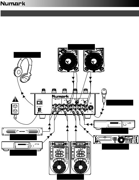
CONNECTION DIAGRAM
TURNTABLES
HEADPHONES
HOUSE AMP
CD BURNER
MICROPHONE
DVD PLAYER
MP3 PLAYER
CD PLAYERS
2
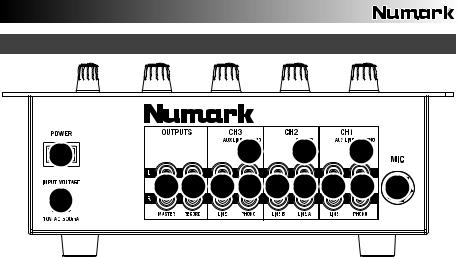
REAR PANEL FEATURES
2 |
|
|
7 |
|
8 |
|
7 |
|
|
|
|
|
|
|
|
|
|
3 |
4 |
6 |
5 |
6 |
6 |
6 |
5 |
9 |
1 |
|
|
|
|
|
|
|
|
1.AC IN – Use the included power adapter to connect the mixer to a power outlet. While the power is switched off, plug the power supply into the mixer first, then plug the power supply into a power outlet.
Note: The mixer is designed to work with the included AC power supply only. Using an incompatible power supply could result in damage to the unit.
2.POWER SWITCH – Turns the mixer on and off. Turn on the mixer after all input devices have been connected and before you turn on amplifiers. Turn off amplifiers before you turn off the mixer.
3.MASTER OUTPUT (RCA) – Use standard RCA cables to connect this output to a speaker or amplifier system. The level of this output is controlled by the MASTER knob on the top panel.
4.RECORD OUTPUT (RCA) – Use standard RCA cables to connect this output to a recording device, such as a CD recorder or tape deck. The level of this output is based upon pre-master levels.
5.LINE | PHONO INPUTS (RCA) – Connect your audio sources to these inputs. These inputs can accept both line and phono-level signals. (See #7.)
6.LINE INPUTS (RCA) – Connect line-level devices, such as CD players, samplers or audio interfaces, to these inputs.
7.AUX LINE | PHONO SWITCH – Flip this switch to the appropriate position, depending on the device connected to the PHONO INPUTS. If you are using phono-level turntables, set this switch to “PHONO” to provide the additional amplification needed for phono-level signals. If using a line-level device, such as a CD player or sampler, set this switch to “AUX LINE.”
8.GROUNDING TERMINAL – If using phono-level turntables with a grounding wire, connect the grounding wire to these terminals. If you experience a low “hum” or “buzz”, this could mean that your turntables are not grounded.
Note: Some turntables have a grounding wire built into the RCA connection and, therefore, nothing needs to be connected to the grounding terminal.
9.MIC INPUT – Connect a ¼” microphone to this input. Microphone controls are located on the top panel.
3
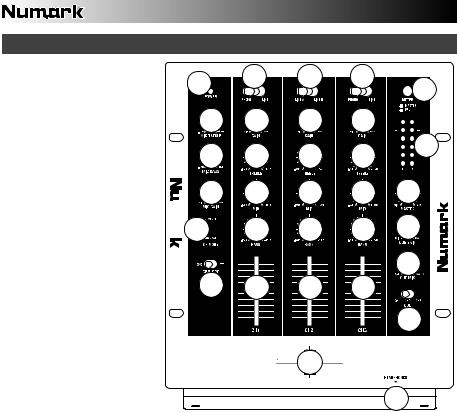
TOP PANEL FEATURES
1.POWER LED – Illuminates
when the mixer is on.
2.MIC TREBLE – Adjusts the high (treble) frequencies of the microphone channel.
Tip: If you experience feedback when using a microphone at loud levels, try turning down the high frequencies.
3.MIC BASS – Adjusts the low (bass) frequencies of the microphone channel.
4.MIC GAIN – Adjusts the audio level of the microphone signal.
5.INPUT SELECTOR – Selects the input source to be routed to the corresponding channel. Input jacks are located on the rear panel.
6.CHANNEL GAIN – Adjusts the corresponding channel’s prefader and pre-EQ gain level.
7.CHANNEL TREBLE – Adjusts the high (treble) frequencies of the corresponding channel.
8.CHANNEL MID – Adjusts the mid-range frequencies of the corresponding channel.
9.CHANNEL BASS – Adjusts the low (bass) frequencies of the corresponding channel.
10.CHANNEL FADER – Adjusts the audio level on the corresponding channel.
1 |
5 |
5 |
5 |
|
|
|
|
16 |
|
|
|
|
|
|
2 |
6 |
6 |
6 |
|
3 |
7 |
7 |
7 |
15 |
|
||||
4 |
8 |
8 |
8 |
14 |
 20
20


 9
9


 9
9


 9
9


 13
13
12
19 
 10
10


 10
10


 10
10

11


 18
18


17
11.CUE MODE SELECTOR – Selects the audio that is sent to the headphones. Switch it to “CH1”, “CH2,” or “CH3” to hear Channels 1, 2, or 3 in the Cue channel.
12.CUE BLEND – Turn to mix between Cue and Program in the headphones. When all the way to the left, only channels routed to CUE will be heard. When all the way right, only the Program mix will be heard.
13.CUE GAIN – Adjusts the level of the headphone audio.
14.MASTER – Adjusts the output volume of the Program mix.
15.STEREO LEVEL INDICATOR – Measures the audio level of the Program mix.
16.METER ASSIGN – Determines whether audio from the Program mix or the Cue channel is sent to the STEREO LEVEL INDICATOR.
17.HEADPHONES – Connect your ¼” headphones to this output for cueing and mix monitoring. Headphone output controls are located on the top panel.
18.CROSSFADER – Blends audio playing between Channels 1 and 3. Sliding this to the left plays Channel 1 and sliding to the right plays Channel 3.
Note: The crossfader is user-replaceable if it should ever wear out. Simply remove the facepanel, then remove the screws holding it in position. Replace the fader with a quality authorized replacement from your local Numark retailer only.
19.CROSSFADER (CF) SLOPE – Adjusts the slope of the crossfader curve. Flip switch to the left for a smooth fade (mixing) or to the right for a sharp cut (scratching).
20.CROSSFADER (CF) MODE – Reverses the assignment of Channels 1 and 3 on the crossfader.
4

INTRODUCCIÓN
Bienvenido al mezclador profesional M4 de 3 canales. He aquí algunas de las características del M4 que le encantarán:
2 entradas fonográficas (con interruptor de supresión “phono-defeat”) y 4 entradas de línea
Entrada de micrófono con ecualizador de 2 bandas
Suave crossfader digital con interruptor de inversión y control rotativo continuo de pendiente
Limitación adelantada en las salidas para auriculares y maestra
Ecualizador de 3 bandas con perillas rotativas de supresión y ganancia en cada canal
Esperamos que el M4 le brinde un buen servicio por muchos años.
Atentamente,
La Gente de Numark
CONTENIDO DE LA CAJA
M4
Adaptador de CA
Guía de inicio rápido
Folleto de información sobre la seguridad y la garantía
REGISTRO
Visite http://www.numark.com y registre su M4. El registro de su producto asegura que podamos mantenerle actualizado con los desarrollos de productos de último momento y brindarle apoyo técnico de categoría mundial en caso de que tenga algún problema.
REGLAS BÁSICAS
1.Asegúrese de que todos los artículos indicados en “Contenido de la caja" estén incluidos en la caja.
2.LEA EL FOLLETO DE INFORMACIÓN SOBRE LA SEGURIDAD Y LA GARANTÍA ANTES DE UTILIZAR EL PRODUCTO.
3.Estudie el diagrama de conexión incluido en esta guía.
4.Coloque el mezclador en una posición adecuada para su funcionamiento.
5.Asegúrese que todos los dispositivos estén apagados y que todos los faders y perillas de ganancia estén en posición «cero».
6.Conecte todas las fuentes de entrada estéreo como se indica en el diagrama.
7.Conecte las salidas estéreo a los amplificadores de potencia, bandejas de cinta magnética y/o otras fuentes de audio.
8.Enchufe todos los dispositivos al suministro de corriente alterna.
9.Encienda todo en el siguiente orden:
•fuentes de entrada de audio (por ejemplo, giradiscos, reproductores de CD, etc.)
•el mezclador
•por último, cualquier amplificador o dispositivo de salida
10.Al apagar, realice siempre esta operación en sentido inverso:
•apague los amplificadores
•el mezclador
•por último, cualquier dispositivo de entrada
5

DIAGRAMA DE CONEXIÓN
0.03"
GIRADISCOS
AURICULARES
MICRÓFONO
REPRODUCTORE DE DVD
AMPLIFICADOR DE AUDITORIO
REPRODUCTORE DE MP3
GRABADORA DE CD
REPRODUCTORES DE CD
6
Loading...