


C2
QUICKSTART GUIDE
ENGLISH ( 3 – 7 )
MANUAL DE INICIO RÁPIDO
ESPAÑOL ( 9 – 13 )
GUIDE D’UTILISATION RAPIDE
FRANÇAIS ( 15 – 19 )
MANUALE RAPIDO DI UTILIZZAZIONE
ITALIANO ( 21 – 25 )
KURZANLEITUNG
DEUTSCH ( 27 – 31 )


3
INTRODUCTION
Welcome to the C2 – a professional 19”, 4-channel mixer. Here are some of the features that you will come
to love about this device:
8 line, 3 phono, & 2 mic inputs
Fader-start crossfader with front panel controls
Split/blend cue options
Panning on master fader with stereo/mono switch
5-band ±6/±12dB EQ with rear panel defeat
Master balanced XLR outputs with stereo/mono controls
Cues on each channel with cue/send rear output for sampling and booth cue monitor
Channel gain control with PFL meter
Neutrik™ “Combo” connector (1/4” or XLR plug) for DJ mic
Auto-talkover mic input with bass and treble
Tape out for direct recording
Front panel BNC light connector
Zone output
We hope that the C2 serves you well for many years to come.
Sincerely,
The People of Numark
BOX CONTENTS
C2
IEC Power Cable
Quickstart Guide
Safety & Warranty Information Booklet
REGISTRATION
Please go to http://www.numark.com to register your C2. Registering your product ensures that we can keep
you up-to-date with any last-minute product developments and provide you with world-class technical
support, should you run into any problems.
GROUND RULES
1. Make sure all items listed in the BOX CONTENTS section are included in the box.
2. READ SAFETY & WARRANTY INFORMATION BOOKLET BEFORE USING THE PRODUCT.
3. Study the connection diagram in this guide.
4. Place mixer in an appropriate position for operation.
5. Make sure all devices are turned off and all faders and gain knobs are set to “zero.”
6. Connect all stereo input sources as indicated in the diagram.
7. Connect the stereo outputs to power amplifier(s), tape decks, and/or other audio sources.
8. Plug all devices into AC power.
9. Switch everything on in the following order:
• Audio input sources (i.e. turntables, CD players, etc.)
• Mixer
• Last, any amplifiers or output devices
10. When turning off, always reverse this operation by turning off:
• Amplifiers
• Mixer
• Last, any input devices
4
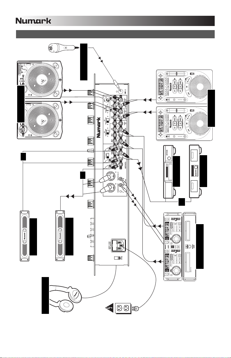
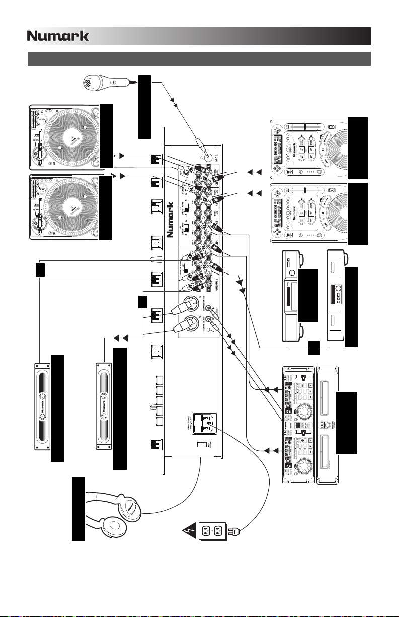
CONNECTION DIAGRAM
BOOTH AMP
HOUSE AMP
TURNTABLES
MICROPHONE
CD PLAYERS
DUAL CD PLAYER
CD BURNER
TAPE DECK
HEADPHONES
O
R
O
R
OR
5
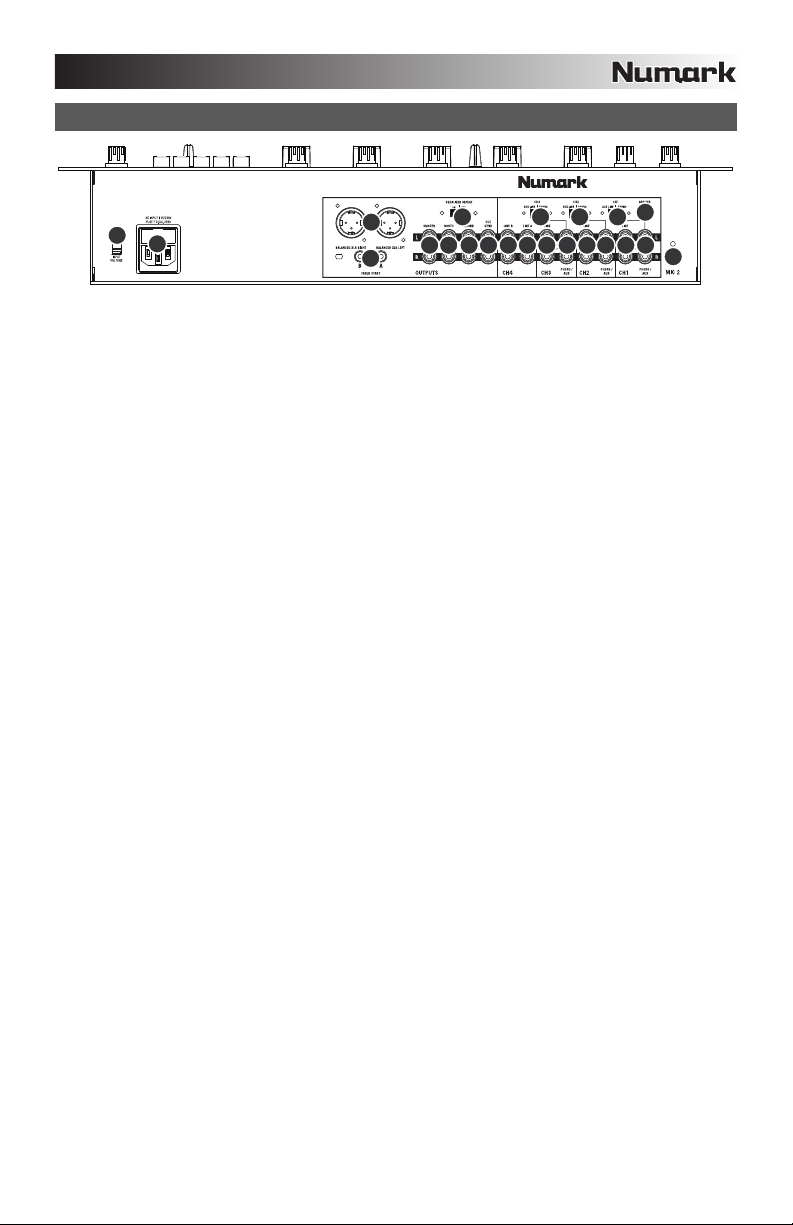
REAR PANEL FEATURES
141414446789
10
13
14
11
5
2
33312
1. LINE | PHONO INPUTS (RCA) – Connect your audio sources to these inputs. These inputs can
accept both line and phono-level signals.
2. GROUNDING TERMINAL – If using phono-level turntables with a grounding wire, be sure to connect
the grounding wire to these terminals. If you experience a low “hum” or “buzz”, this could mean that
your turntables are not grounded.
Note: Some turntables have the grounding wire built into the RCA connection and, therefore, nothing
needs to be connected to the grounding terminal.
3. LINE | PHONO SWITCH – Flip this switch to the appropriate position, depending on the device
connected to the PHONO INPUTS. If using phono-level turntables, set this switch to “PHONO” to
provide the additional amplification needed for phono-level signals. If using a line-level device, such as
a CD player or sampler, set this switch to “LINE.”
4. LINE INPUTS (RCA) – Connect line-level devices, such as CD players, samplers or audio interfaces,
to these inputs.
5. MIC 2 INPUT – If you would like to use an additional ¼” microphone, connect it to this input. Adjust the
levels for this input with the MIC GAIN CONTROLS.
6. CUE / SEND OUTPUT – Connect external monitors to this output to monitor pre-fader audio sent to the
Cue Channel (see #20 under TOP PANEL FEATURES).
7. RECORD OUTPUT (RCA) – Use standard RCA cables to connect this Record output to a recording
device, such as a CD recorder or tape deck. The level of this output is based upon pre-master levels.
8. BOOTH OUTPUT (RCA) – Connect an external monitoring device, such as powered monitors, a PA
system, or a home stereo, to this output. The controls this output are located on the front panel.
9. MASTER OUTPUT (RCA) – Use standard RCA cables to connect this Master output to a speaker or
amplifier system. The level of this output is controlled by the Master knob on the top panel.
10. MASTER OUTPUT (BALANCED) –
Connect this low-impedance XLR output to a PA system or powered
monitors.
The level of this output is controlled by the Master knob on the top panel.
11. FADER START – If you would like to use the mixer’s “fader start” to automatically start and cue music
from external devices via the CROSSFADER, connect these outputs to your fader start-compatible
device. You can use standard 1/8” stereo cables to make these connections.
12. EQUALIZER DEFEAT – Switch this to turn off the GRAPHIC EQUALIZER (see #12 under TOP
PANEL FEATURES).
13. POWER IN – Use the included power cable to connect the mixer to a power outlet. While the power is
switched off, plug the power supply into the mixer first, then plug the power supply into a power outlet.
14. VOLTAGE SELECTOR – This 2-position switch sets the AC input voltage for the speaker. U.S. users
should set this switch to “100-120V” whereas U.K. and most European users will need to set this to
“220-240V.”
6
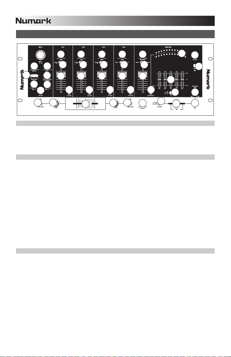
TOP PANEL FEATURES
11 11
22 22
33 33
20
20
20 20 20
14
8
4
4
5
6
77
11 11
9
9
10
12
13
15
16
17
18
19
21
22
23
25
26
24
INPUT CONTROLS
1. CHANNEL FADER – Adjusts the audio level of the corresponding channel.
2. INPUT SELECTOR – Selects the input source to be routed to the corresponding channel. Input jacks
are located on the rear panel.
3. CHANNEL GAIN – Adjusts the channel’s pre-fader and pre-EQ gain level.
MICROPHONE CONTROLS
4. MIC TREBLE & BASS – Adjusts the treble (high) and bass (low) frequencies of the audio for both mic
inputs.
Tip: If you experience feedback when using a microphone at loud levels, try turning down the high
(treble) frequencies.
5. TALKOVER SWITCH – Toggles between three “talkover” settings, allowing you to speak over the
music. (Talkover only applies to MIC 1. MIC 2’s level can only be controlled by its MIC GAIN knob.)
-12dB – Reduces the combined levels of Channels 1-4 to -12dB (an appropriate “talkover” level).
ON – Leaves Channels 1-4 at the levels you designated while the mic remains on.
AUTO – Automatically reduces the combined levels of Channels 1-4 to -12dB whenever you talk
into the DJ MIC.
6. TALKOVER SENSITIVITY – Adjusts the volume threshold at which auto-talkover activates. The higher
the sensitivity, the quieter you need to speak into the mic to activate auto-talkover.
7. MIC GAIN – Adjusts the audio level of the microphone signal. The MIC 1 knob controls the volume of
DJ mic input. The MIC 2 knob controls the volume of the MIC 2 input.
8. MIC 1 INPUT – Connect a microphone to this input with an XLR or ¼” cable.
CROSSFADER CONTROLS
9. CROSSFADER ASSIGN – Selects which input channel will be heard when the crossfader is moved
towards this knob. All channels not assigned will remain active.
10. CROSSFADER – Blends audio between the channels assigned to the left and right side of the
crossfader.
Note: The crossfader is user-replaceable if it should ever wear out. Simply remove the facepanel, then
remove the screws holding it in position. Replace the fader with a quality authorized replacement from
your local Numark retailer only.
11. FADER START – Enables or disables “fader start” on the corresponding side of the crossfader. When
fader start is enabled on one side, moving the crossfader toward that side will cause any fader start-
compatible device (connected to the FADER START output on the rear panel) to start playing.

7
EQUALIZER
12. GRAPHIC EQUALIZER (EQ) – Adjusts the high, mid-range, and low frequencies of the combined
audio output from Channels 1-4. EQ compensates for differences in source material sound quality.
The center frequencies of this 5-band graphic equalizer are 63Hz, 250Hz, 1kHz, 4kHz and 16kHz.
Faders have a center detent for an accurate "flat” response.
Tips:
Boosting (increasing) the 63Hz band will increase the deep bass tones and “kick drum” sounds,
but could cause your amplifiers to “clip” or distort if set too high.
Slightly cutting (decreasing) the 250Hz and 1kHz bands will give the sound some extra clarity.
Boosting the 16kHz band will give the audio a sharper tone.
As a general rule, the less equalization, the better.
13. EQ ADJUST – Determines how much the equalization changes when you move the EQ faders. When
this button is raised, the EQ faders will adjust each band by 12dB. When the button is pressed, the EQ
faders will adjust each band by 6dB.
OUTPUT CONTROLS
14. MASTER FADER – Adjusts the output volume of the Program mix.
15. STEREO / MONO – Adjusts the Program mix for stereo or mono operation.
16. BALANCE – Adjusts the balance of right to left audio of the Program mix.
17. BOOTH FADER– Adjusts the audio level from the Booth output level. (This can also be used to supply
line level audio to a lighting controller or to lights that are sound activated.)
18. METER MODE – Determines whether audio from the Program mix or Cue channel is sent to the
STEREO LEVEL INDICATOR.
19. STEREO LEVEL INDICATOR – Monitors the audio level of the Program mix or Cue channel,
depending on the position of the METER MODE button.
CUE CONTROLS
20. CUE / SEND – Sends the pre-fader audio Cue channel for monitoring.
21. CUE MODE – When pressed, this button sends all audio in the Cue channel to the left side of the
headphones and the Program mix to the right side of the headphones. When raised, you may control
the balance of the Cue channel and Program mix with the Cue Blend fader.
HEADPHONE CONTROLS
22. MIX – Slide this to mix the Cue channel and Program mix in the headphones. When all the way to the
left, only channels routed to the Cue channel will be heard. When all the way to the right, only the
Program mix will be heard. The CUE MODE button must be set to BLEND for this fader to work (see
#21).
23. HEADPHONE GAIN – Adjusts the volume level of the headphone output.
24. HEADPHONE OUTPUT – Connect your ¼” headphones to this output for cueing and mix monitoring.
POWER
25. 12V LIGHT CONNECTION – You can connect a 12-volt gooseneck lamp here.
26. POWER SWITCH – Turns the mixer on and off. Turn on the mixer after all input devices have been
connected and before you turn on amplifiers. Turn off amplifiers before you turn off the mixer.

9
INTRODUCCIÓN
Bienvenido al C2 —el mezclador profesional de 5 canales y 19 pulgadas. He aquí algunas de las
características de este dispositivo que seguramente le encantarán:
8 entradas de línea, 3 fonográficas y 2 de micrófono
Crossfader de Fader-start con controles en el panel frontal
Opciones de búsqueda de punto inicial (cue) de división y combinación
Paneo en el fader maestro con conmutador estéreo/mono
Ecualizador de 5 bandas de ±6/±12 dB con supresión en el panel trasero
Salidas maestras XLR balanceadas con controles estéreo/mono
Búsqueda de punto inicial (cue) en cada canal con salida trasera de cue/envío para muestreo y
monitor de cue de cabina
Control de ganancia de canal con medidor PFL
Conector Neutrik™ “Combo” (enchufe de 1/4” o XLR) para el micrófono de DJ
Entrada de micrófono de talkover (hablar superpuesto a la música) automático con graves y agudos
Salida para grabación directa en cinta
Conector BNC de luz en el panel frontal
Salida de zona
Esperamos que el C2 le brinde un buen servicio por muchos años.
Atentamente,
La Gente de Numark
CONTENIDO DE LA CAJA
C2
Cable de alimentación IEC
Guía de inicio rápido
Folleto de información sobre la seguridad y la garantía
REGISTRO
Visite http://www.numark.com y registre su C2. El registro de su producto asegura que podamos mantenerle
actualizado con los desarrollos de productos de último momento y brindarle apoyo técnico de categoría
mundial en caso de que tenga algún problema.
REGLAS BÁSICAS
1. Asegúrese de que todos los artículos indicados en “Contenido de la caja" estén incluidos en la caja.
2. LEA EL FOLLETO DE INFORMACIÓN SOBRE LA SEGURIDAD Y LA GARANTÍA ANTES DE
UTILIZAR EL PRODUCTO.
3. Estudie el diagrama de conexión incluido en esta guía.
4. Coloque el mezclador en una posición adecuada para su funcionamiento.
5. Asegúrese que todos los dispositivos estén apagados y que todos los faders y perillas de ganancia
estén en posición «cero».
6. Conecte todas las fuentes de entrada estéreo como se indica en el diagrama.
7. Conecte las salidas estéreo a los amplificadores de potencia, bandejas de cinta magnética y/o otras
fuentes de audio.
8. Enchufe todos los dispositivos al suministro de corriente alterna.
9. Encienda todo en el siguiente orden:
• fuentes de entrada de audio (por ejemplo, giradiscos, reproductores de CD, etc.)
• el mezclador
• por último, cualquier amplificador o dispositivo de salida
10. Al apagar, realice siempre esta operación en sentido inverso:
• apague los amplificadores
• el mezclador
• por último, cualquier dispositivo de entrada
10
DIAGRAMA DE CONEXIÓN
AMPLIFICADOR DE CABINA
AMPLIFICADOR DE AUDITORIO
GIRADISCOS
MICRÓFONO
REPRODUCTOR
DE CD DUAL
GRABADORA
DE CD
CINTA DE CASSETTE
AURICULARES
O
O
OR
GIRADISCOS
REPRODUCTOR
DE CD
REPRODUCTOR
DE CD

11
CARACTERÍSTICAS DEL PANEL TRASERO
141414446789
10
13
14
11
5
2
33312
1. ENTRADAS DE LÍNEA | FONOGRÁFICA (RCA) – Conecte sus fuentes de audio a estas entradas.
Estas entradas pueden aceptar señales de nivel de línea y fonográfico.
2. TERMINAL DE TIERRA – Si usa giradiscos de nivel fonográfico con cable de conexión a tierra,
asegúrese de conectar dicho cable a estos terminales. Si se experimenta un zumbido grave, puede
significar que sus giradiscos no están conectados a tierra.
Nota: Algunos giradiscos tienen el cable de conexión a tierra incorporado a la conexión RCA y, por lo
tanto, no es necesario conectar nada al terminal de tierra.
3. INTERRUPTOR DE ENTRADA DE LÍNEA | FONOGRÁFICA – Coloque este conmutador en la
posición apropiada, en función del dispositivo conectado a las entradas LINE | PHONO. Si usa
giradiscos de nivel fonográfico, coloque este conmutador en “PHONO” para proporcionar la
amplificación adicional necesaria para las señales de este nivel. Si usa un dispositivo de nivel de
línea, tal como un reproductor de CD o muestreador, coloque este conmutador en “LINE”.
4. ENTRADAS DE LÍNEA (RCA) – Estas entradas se usan para conectar dispositivos de nivel de línea,
tales como reproductores de CD, muestreadores o interfaces de audio.
5. ENTRADA DE MICRÓFONO 2 – Si desea usar un micrófono de ¼” adicional, conéctelo a esta
entrada. Ajuste los niveles de esta entrada con los controles MIC GAIN (Ganancia de micrófono).
6. SALIDA DE CUE / ENVÍO – Conecte a esta salida monitores externos a fin de monitorear el audio pre-
fader enviado al cana de cue (consulte el Nº 20 en CARACTERÍSTICAS DEL PANEL SUPERIOR)..
7. SALIDA PARA GRABACIÓN (RCA) – Use cables RCA estándar para conectar esta salida a un
dispositivo de grabación, tal como un grabador de CD o bandeja de cinta. El nivel de esta salida se
basa en los niveles pre-master.
8. SALIDA PARA CABINA (RCA) – Use cables RCA estándar para conectar esta salida a un sistema de
monitoreo de cabina. El nivel de esta salida se controla con la perilla BOOTH del panel superior.
9. SALIDA MAESTRA (RCA) – Use cables RCA estándar para conectar esta salida maestra a un
sistema de altavoces o amplificador. El nivel de esta salida se controla con la perilla MASTER del
panel superior.
10. SALIDA MAESTRA (BALANCEADA) – Esta salida XLR de baja impedancia sirve para conectar a un
sistema de megafonía o monitores alimentados. El nivel de esta salida se controla con el fader
MASTER del panel superior.
11. FADER START – Si desea usar el fader-start del mezclador para iniciar y buscar automáticamente el
punto inicial de música de dispositivos externos a través del crossfader del mismo, conecte estas
salidas a su dispositivo compatible con fader-start. Puede usar cables estéreo estándar 1/8” para
efectuar estas conexiones.
12. SUPRESIÓN DEL ECUALIZADOR – Use este control para desactivar el ECUALIZADOR GRÁFICO
(consulte el Nº 12 en CARACTERÍSTICAS DEL PANEL SUPERIOR).
13. ENTRADA DE ALIMENTACIÓN - Use el cable de alimentación incluido para conectar el mezclador a
un tomacorriente alimentado. Con la alimentación eléctrica desconectada, enchufe la fuente de
alimentación al mezclador primero, y luego al tomacorriente.
14. SELECTOR DE VOLTAJE – Este conmutador de 2 posiciones establece el voltaje de entrada de CA
del altavoz. Los usuarios de EE.UU. deben colocar este conmutador en “100-120V”, mientras que los
del Reino Unido y la mayoría de los países europeos deben colocarlo en “220-240V”.
 Loading...