

nordictrack.com
Model No. NTEX02121.2
Serial No.
Write the serial number in the space
above for reference.
Serial Number
Decal
ACTIVATE YOUR
WARRANTY
To register your product and
activate your warranty today,
go to my.nordictrack.com.
USER’S MANUAL
CUSTOMER CARE
For service at any time, go to
support.nordictrack.com.
Or call 1-800-TO-BE-FIT
(1-800-862-3348)
Mon.–Fri. 6 a.m.–6 p.m. MT
Sat. 8 a.m.–12 p.m. MT
Please do not contact the store.
CAUTION
Read all precautions and
instructions in this manual before
using this equipment. Keep this
manual for future reference.
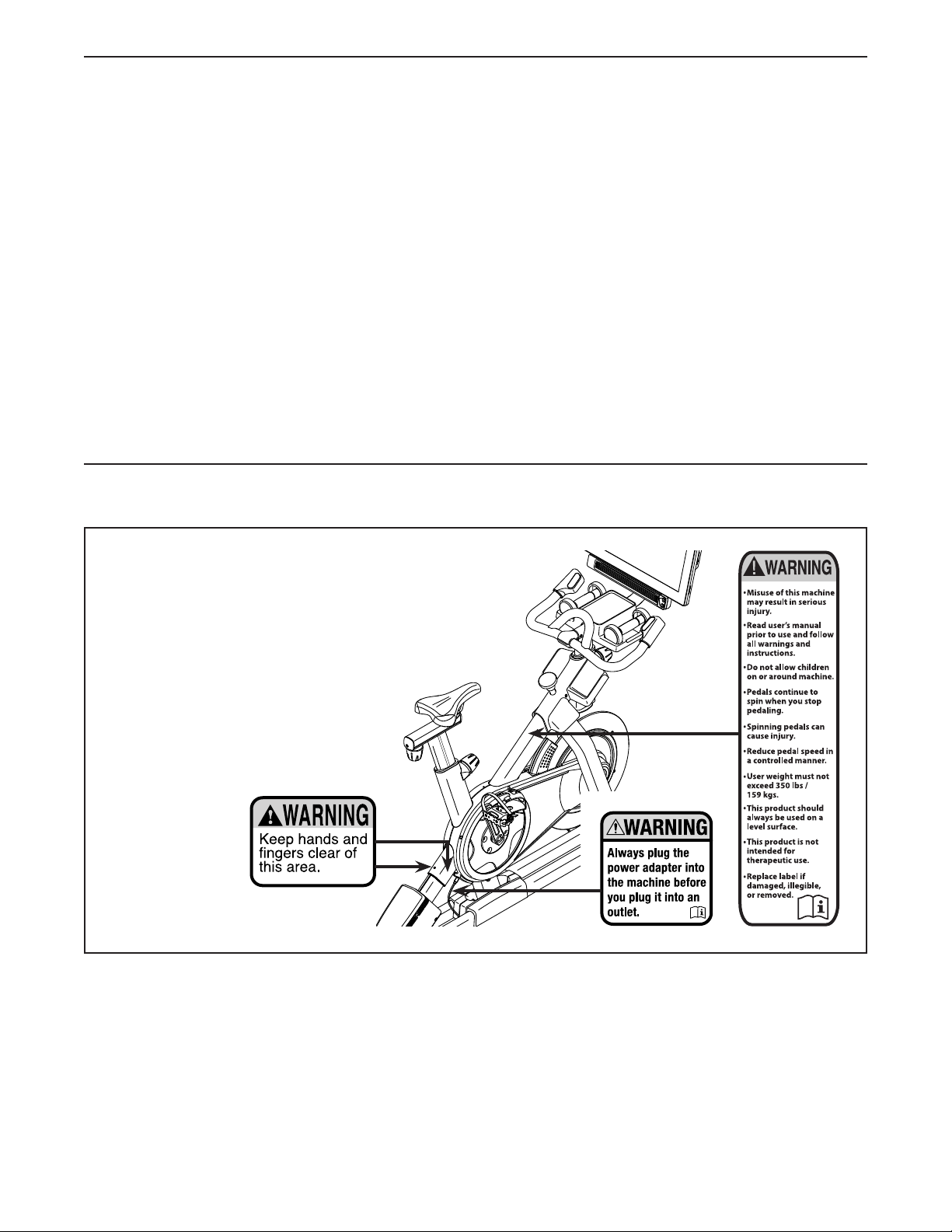
TABLE OF CONTENTS
428421
WARNING DECAL PLACEMENT . . . . . . . . . . . . . . . . . . . . . . . . . . . . . . . . . . . . . . . . . . . . . . . . . . . . . . . . . . . . . . .2
IMPORTANT PRECAUTIONS ..................................................................3
BEFORE YOU BEGIN. . . . . . . . . . . . . . . . . . . . . . . . . . . . . . . . . . . . . . . . . . . . . . . . . . . . . . . . . . . . . . . . . . . . . . . .5
PART IDENTIFICATION CHART. . . . . . . . . . . . . . . . . . . . . . . . . . . . . . . . . . . . . . . . . . . . . . . . . . . . . . . . . . . . . . . .6
ASSEMBLY . . . . . . . . . . . . . . . . . . . . . . . . . . . . . . . . . . . . . . . . . . . . . . . . . . . . . . . . . . . . . . . . . . . . . . . . . . . . . . . .7
HOW TO USE THE STUDIO CYCLE ...........................................................15
HOW TO USE THE CONSOLE. . . . . . . . . . . . . . . . . . . . . . . . . . . . . . . . . . . . . . . . . . . . . . . . . . . . . . . . . . . . . . . .17
MAINTENANCE AND TROUBLESHOOTING .....................................................28
FCC INFORMATION . . . . . . . . . . . . . . . . . . . . . . . . . . . . . . . . . . . . . . . . . . . . . . . . . . . . . . . . . . . . . . . . . . . . . . . .30
EXERCISE GUIDELINES ....................................................................31
PART LIST. . . . . . . . . . . . . . . . . . . . . . . . . . . . . . . . . . . . . . . . . . . . . . . . . . . . . . . . . . . . . . . . . . . . . . . . . . . . . . . .32
EXPLODED DRAWING. . . . . . . . . . . . . . . . . . . . . . . . . . . . . . . . . . . . . . . . . . . . . . . . . . . . . . . . . . . . . . . . . . . . . .34
ORDERING REPLACEMENT PARTS. . . . . . . . . . . . . . . . . . . . . . . . . . . . . . . . . . . . . . . . . . . . . . . . . . . Back Cover
LIMITED WARRANTY. . . . . . . . . . . . . . . . . . . . . . . . . . . . . . . . . . . . . . . . . . . . . . . . . . . . . . . . . . . . . . . Back Cover
WARNING DECAL PLACEMENT
This drawing shows the location(s) of the warning
decal(s). If a decal is missing or illegible, see
the front cover of this manual and request a
free replacement decal. Apply the decal in
the location shown. Note: The decal(s) may
not be shown at actual size.
NORDICTRACK and IFIT are registered trademarks of ICON Health & Fitness, Inc. The Bluetooth® word mark
and logos are registered trademarks of Bluetooth SIG, Inc. and are used under license. Google Maps is a
trademark of Google LLC. Wi-Fi is a registered trademark of Wi-Fi Alliance. WPA and WPA2 are trademarks of
Wi-Fi Alliance.
2

IMPORTANT PRECAUTIONS
WARNING: To reduce the risk of serious injury, read all important precautions and
instructions in this manual and all warnings on your studio cycle before using your studio cycle.
ICON assumes no responsibility for personal injury or property damage sustained by or through the
use of this product.
1. It is the responsibility of the owner to ensure
that all users of the studio cycle are adequately informed of all precautions.
2. Before beginning any exercise program,
consult your physician. This is especially
important for persons over age 35 or persons
with pre-existing health problems.
3. The studio cycle is not intended for use by
persons with reduced physical, sensory, or
mental capabilities or lack of experience and
knowledge, unless they are given supervision or instruction about the use of the
studio cycle by someone responsible for
their safety.
4. Use the studio cycle only as described in this
manual.
5. The studio cycle is intended for home use
only. Do not use the studio cycle in a commercial, rental, or institutional setting.
6. Keep the studio cycle indoors, away from
moisture and dust. Do not put the studio
cycle in a garage or covered patio, or near
water.
9. Always plug the power adapter into the
studio cycle before you plug it into an outlet.
10. Keep children under age 16 and pets away
from the studio cycle at all times.
11. The studio cycle should not be used by
persons weighing more than 350 lbs.
(159 kg).
12. Wear appropriate clothes while exercising;
do not wear loose clothes that could become
caught on the studio cycle. Always wear athletic shoes for foot protection.
13. Be careful when mounting and dismounting
the studio cycle.
14. Always keep your back straight while using
the studio cycle; do not arch your back.
15. The studio cycle does not have a freewheel;
the pedals will continue to move until the
flywheel stops. Reduce your pedaling speed
in a controlled way.
16. To stop the flywheel quickly, press the brake
knob downward.
7. Place the studio cycle on a level surface, with
a mat beneath it to protect the floor or carpet.
Make sure that there is at least 2 ft. (0.6 m) of
clearance around the studio cycle.
8. Inspect and properly tighten all parts each
time the studio cycle is used. Replace any
worn parts immediately.
17. Over exercising may result in serious injury
or death. If you feel faint, if you become short
of breath, or if you experience pain while
exercising, stop immediately and cool down.
3

STANDARD SERVICE PLANS
4
BEFORE YOU BEGIN
Congratulations for selecting the revolutionary
NORDICTRACK® COMMERCIAL S22I STUDIO
CYCLE. The COMMERCIAL S22I STUDIO CYCLE is
unlike any ordinary exercise bike.
With full adjustability, an interactive wireless touchscreen console, an incline system that simulates
real-world terrain, and an array of other features, the
COMMERCIAL S22I STUDIO CYCLE provides an
immersive in-home studio cycling experience.
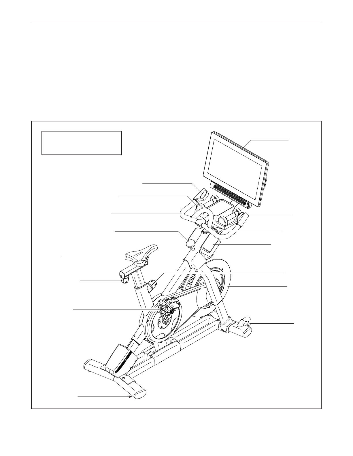
Length: 2 ft. 11 in. (89 cm)
Width: 1 ft. 10 in. (56 cm)
Incline/Decline Control
Hand Weight
Handlebar
For your benefit, read this manual carefully before
you use the studio cycle. If you have questions after
reading this manual, please see the front cover of this
manual. To help us assist you, note the product model
number and serial number before contacting us. The
model number and the location of the serial number
decal are shown on the front cover of this manual.
Before reading further, please familiarize yourself with
the parts that are labeled in the drawing below.
Console
Resistance
Control
Saddle
Carriage Knob
Pedal/Strap
Leveling Foot
Brake Knob
Post Knob
Accessory Tray
Post Knob
Flywheel
Wheel
5
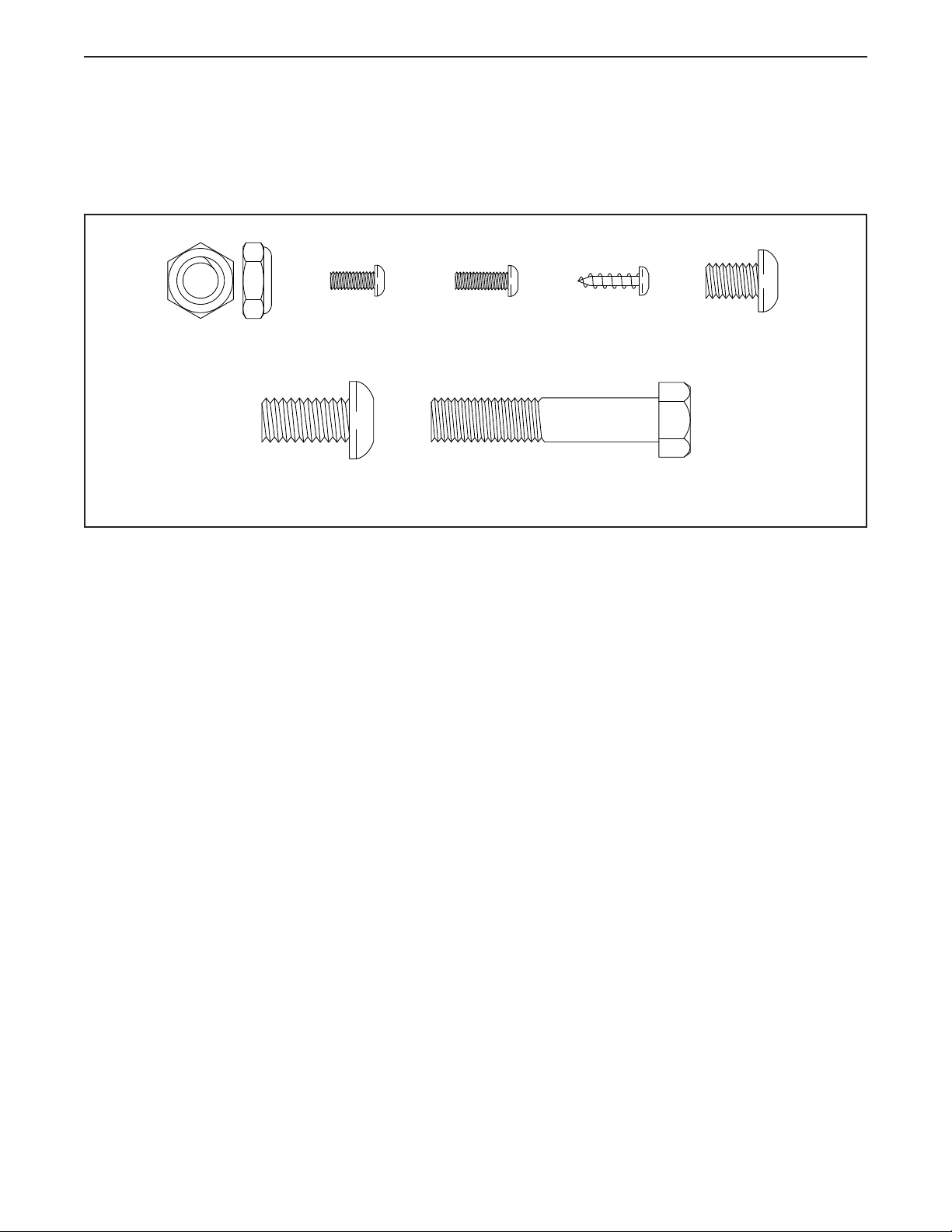
PART IDENTIFICATION CHART
Use the drawings below to identify the small parts needed for assembly. The number in parentheses below each
drawing is the key number of the part, from the PART LIST near the end of this manual. The number following the
key number is the quantity needed for assembly. Note: If a part is not in the hardware kit, check to see if it
has been preassembled. Extra parts may be included.
M10 Jam Nut
(95)–1
M4 x 10mm
Machine
Screw (12)–2
M10 x 20mm
Screw (105)–12
M4 x 12mm
Machine
Screw (102)–4
M10 x 52mm Bolt (94)–1
M4 x 14mm
Screw (17)–4
M8 x 12mm
Patch Screw
(93)–4
6
ASSEMBLY
• Assembly requires two persons.
• Place all parts in a cleared area and remove the
packing materials. Do not dispose of the packing
materials until you complete all assembly steps.
• To identify small parts, see page 6.
• To avoid damaging parts, do not use power tools.
1. Go to my.nordictrack.com on your computer
and register your product.
• documents your ownership
• activates your warranty
• ensures priority customer support if assistance
is ever needed
Note: If you do not have internet access, call
Customer Care (see the front cover of this
manual) and register your product.
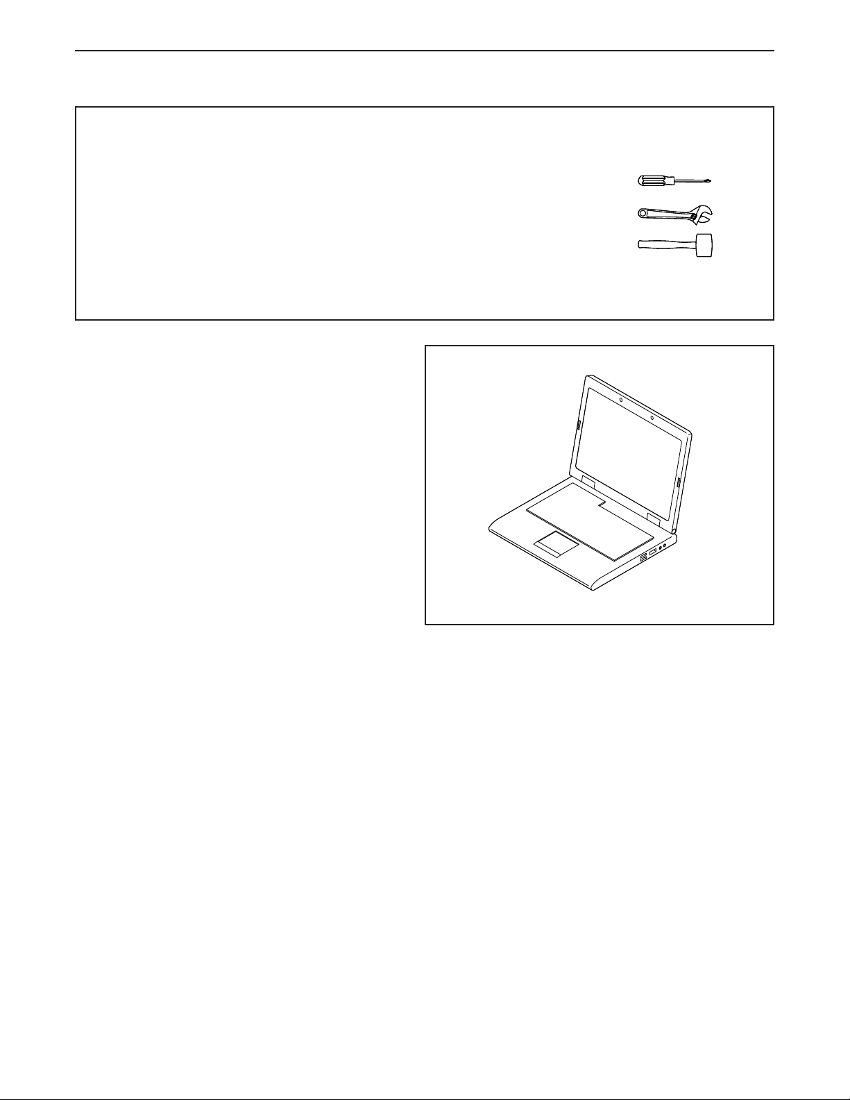
• In addition to the included tool(s), assembly
requires the following tool(s):
one Phillips screwdriver
one adjustable wrench
one rubber mallet
Assembly may be easier if you have a set of
wrenches.
1
7
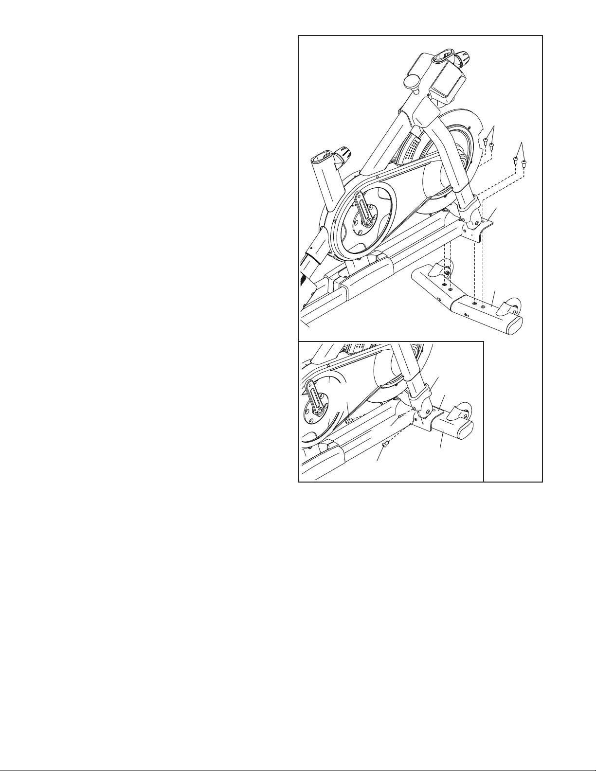
2. Attach the Front Stabilizer (3) to the Base (2)
with four M10 x 20mm Screws (105); do not
fully tighten the Screws yet.
See the inset drawing. Finish attaching
the Front Stabilizer (3) with two additional
M10 x 20mm Screws (105).
Then, fully tighten all six M10 x 20mm
Screws (105).
See the inset drawing. Press the right Leg
Cover (64) downward and attach it to the Base
(2) with an M4 x 10mm Machine Screw (12).
Then, attach the left Leg Cover (not shown)
in the same way.
2
105
105
2
3
105
64
2
12
3
105
8
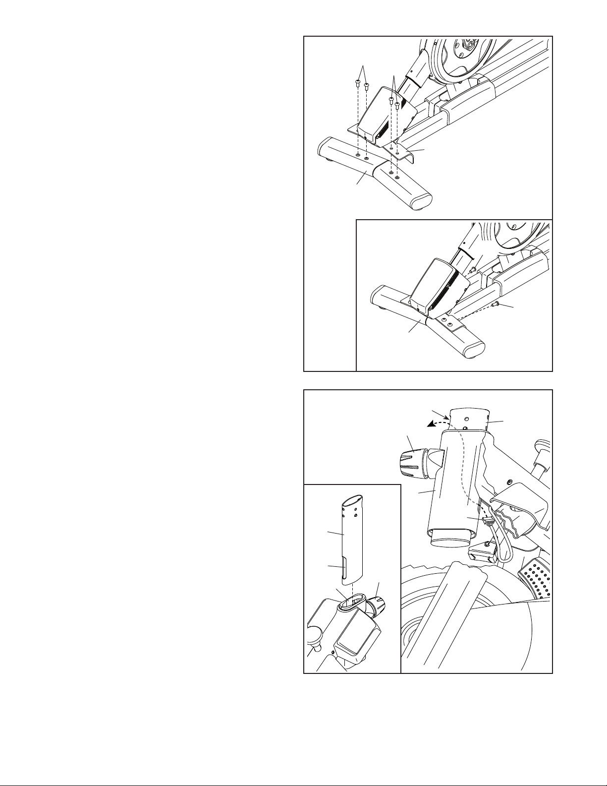
3. Attach the Rear Stabilizer (4) to the Base (2)
with four M10 x 20mm Screws (105); do not
fully tighten the Screws yet.
See the inset drawing. Finish attaching
the Rear Stabilizer (4) with two additional
M10 x 20mm Screws (105).
Then, fully tighten all six M10 x 20mm
Screws (105).
3
105
105
2
4
105
105
4. See the inset drawing. Orient the Handlebar
Post (7) so that the lower slot (A) is on the side
shown.
Next, loosen the indicated Post Knob (100) and
insert the Handlebar Post (7) into the Frame
(1) until the lower end of the Handlebar Post is
below the Frame. Then, tighten the Post Knob.
Then, insert the end of the Lower Wire (122) into
the Frame (1) and the Handlebar Post (7) and
pull it out of the upper slot (B) in the Handlebar
Post as shown by the dashed line at the right.
4
4
B
7
100
1
122
7
A
100
1
9
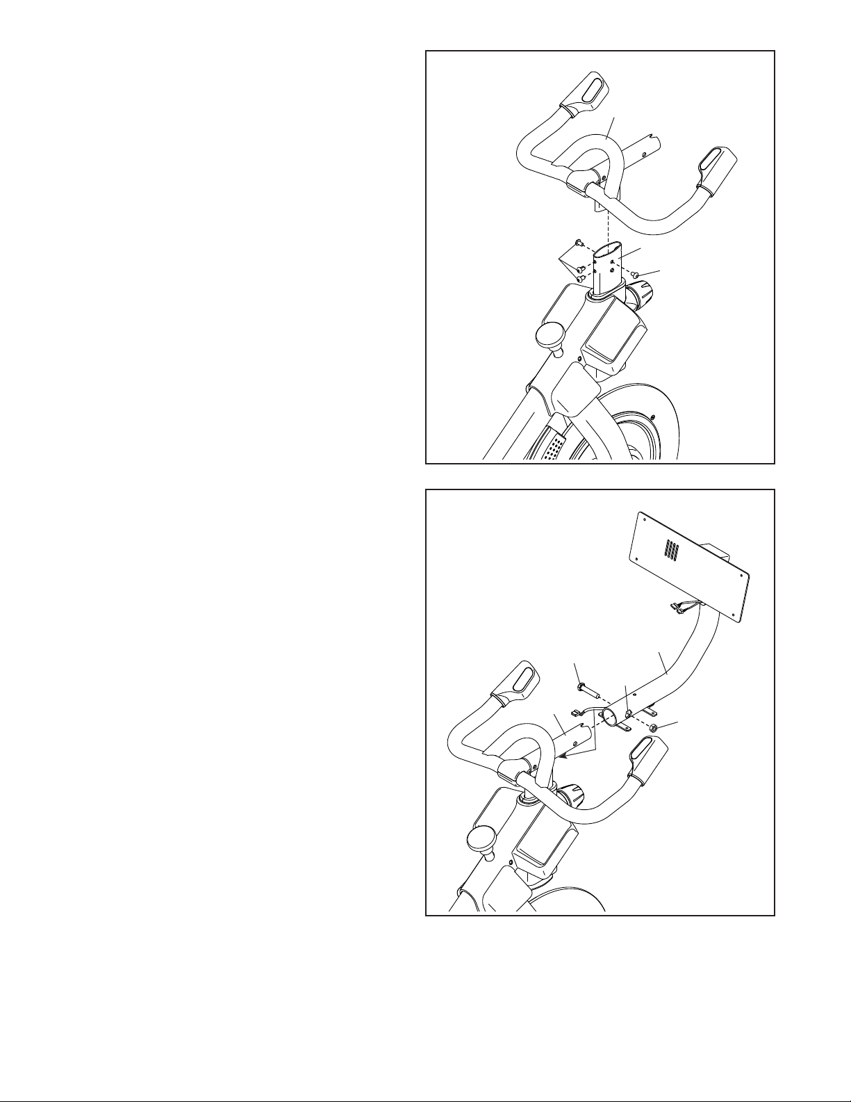
5. Insert the Handlebar (97) into the Handlebar
Post (7). Attach the Handlebar with four
M8 x 12mm Patch Screws (93); start all the
Patch Screws, and then tighten them.
5
97
6. Tip: Avoid pinching the wires (C). Slide the
Console Support (8) onto the Handlebar (97).
Attach the Console Support (8) with an
M10 x 52mm Bolt (94) and an M10 Jam Nut
(95); make sure that the Jam Nut is in the
hexagonal hole (D). Do not fully tighten the
Bolt yet.
93
6
Avoid pinching
the wires (C)
94
7
93
8
D
10
97
95
C
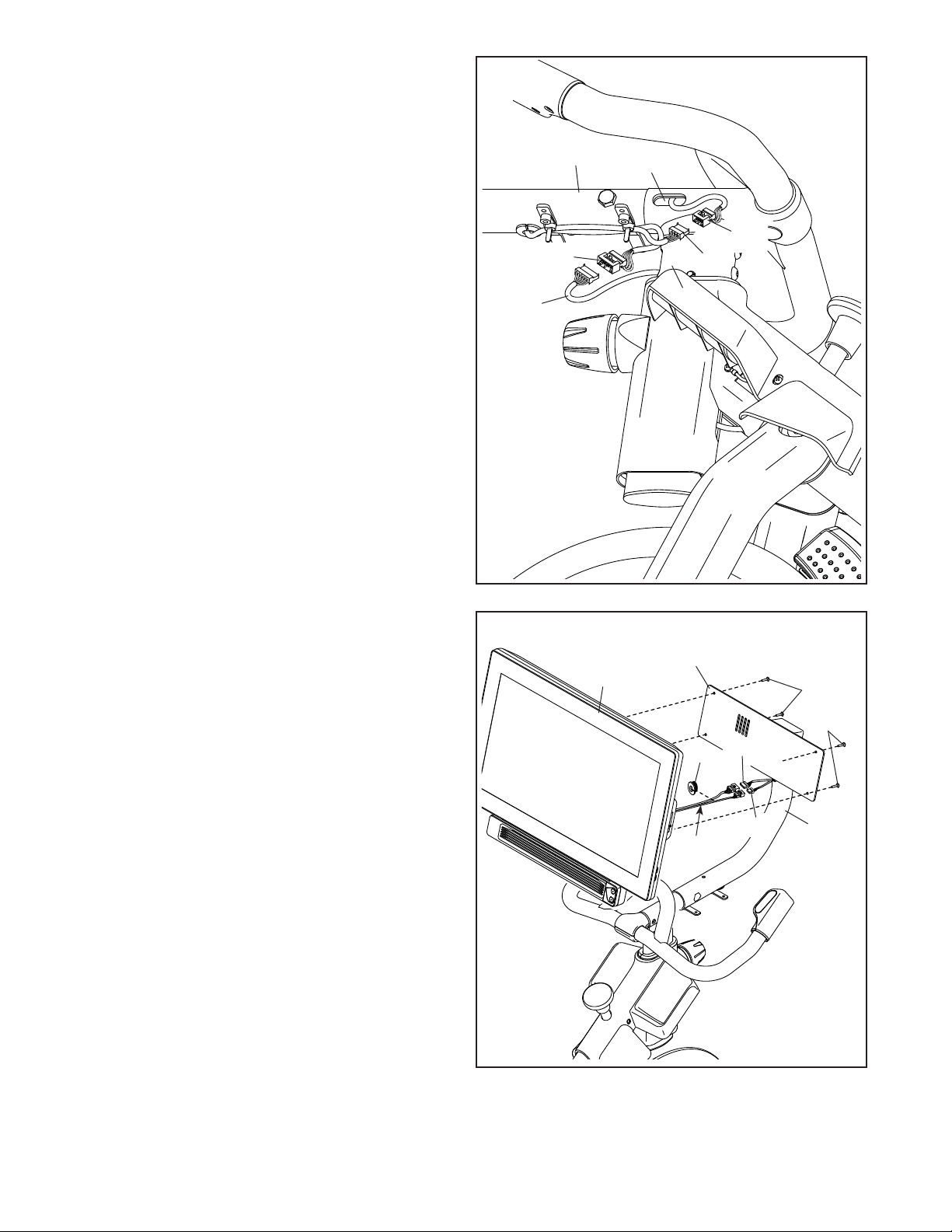
7. Look under the Console Support (8) and identify
the Upper Wire (123), which has a larger connector than the Extension Wire (124).
Connect the Upper Wire (123) to the Lower Wire
(122) extending from the Handlebar Post (7).
Then, insert the connectors on both Wires into
the Handlebar Post.
7
8
97
Next, connect the Extension Wire (124) to the
Control Wire (125) extending from the Handlebar
(97). Then, insert the connectors on both Wires
into the Handlebar.
8. Have a second person hold the Console (10)
near the Console Bracket (11). Connect the
Upper Wire (123) and the Extension (124) to the
matching wires (E) on the back of the Console.
Press the Wire Protector (110) around the wires
in the location shown.
Next, insert the connectors into the Console
Support (8), and then press the Wire Protector
(110) into the Console Support. Tip: It may
be helpful to insert the connectors into the
Console Support one at a time.
Tip: Avoid pinching the wires. If necessary,
adjust the tilt of the Console Bracket (11) to
make this step easier. Attach the Console (10)
to the Console Bracket with four M4 x 12mm
Machine Screws (102); start all the Machine
Screws, and then tighten them.
125
123
122
8
10
7
11
124
110
E
123
124
102
102
8
11
Avoid pinching
the wires
 Loading...