

Page 1

Programmes After Market Services (PAMS)
Technical Documentation
CIGARETTE LIGHTER
CHARGER LCH–2
Page 2
PAMS
NHB–3
Technical Documentation
AMENDMENT RECORD SHEET
Amendment
Number
Date Inserted By Comments
Cigarette Lighter Charger LCH–2
Original 26/97 Page 2
Page 3

PAMS
NHB–3
Technical Documentation
Cigarette Lighter Charger LCH–2
Contents
Cigarette Lighter Charger LCH–2 Page 4
General Page 4
Technical Summary Page 4
States of Charge and Charge Control Page 4
Charge Indication Page 4
Electrical Specifications Page 5
Functional Description Page 5
General Page 5
Converter Page 5
Oscillator Page 6
Pulse–Width Control Page 6
Current Limiting Page 6
Block Diagram of AL4 Page 7
Circuit Diagram of AL4 Page 8
Layout and Foil Diagrams of AL4 Page 9
Parts List of AL4 Code: 0200315 Page 10
Exploded View Page 13
Assembly Parts Page 13
Cigarette Lighter Charger LCH–2
Original 26/97 Page 3
Page 4

PAMS
NHB–3
Technical Documentation
Cigarette Lighter Charger LCH–2
Related Documentation
4A 0200044 block diagram AL4
3B 0200044 circuit diagram AL4
4F 9853826 layout and foil diagrams
6E 0200044 parts list AL4
S 0675005 exploded view
6E 0260062 assembly parts LCH–2
6E 0260094 assembly parts LCH–2U
General
The LCH–2 cigarette lighter charger is used for charging the battery of the
handportable phone from the 12 or 24 V cigarette lighter socket of a motor vehicle. The charger is provided with LED charging indication.
Technical Summary
Cigarette Lighter Charger LCH–2
States of Charge and Charge Control
The LCH–2 cigarette lighter charger is used for charging a handportable phone
from a car battery. A constant–current or constant–voltage output is provided
depending on the operating state of the phone.
Charge current is supplied through a series switch transistor located in the
phone. When the transistor is on the charger supplies a constant current to the
phone. The phone is then in the rapid charge mode.
When the transistor is off no current is supplied to the phone and the charger is
in the constant–voltage mode.
Once fully charged in the rapid charge mode, the battery is kept full by means
of pulsed charging. Current is switched on and off at a variable duty cycle and a
frequency of a few Hz.
Charge Indication
Charger states are indicated with a dual–colour LED located in the cigarette
lighter charger unit.
In addition, the phone LCD contains a three–bar battery status display, operative when power for the phone is on.
”Charging sequence active” (state A) is indicated by the bars being lit sequentially, starting from the bottom one.
”Battery full” (state B) is indicated by all three bars steadily lit.
Original 26/97 Page 4
Page 5

PAMS
NHB–3
Technical Documentation
Phone operating status LED Display
Cigarette lighter charger connected
to vechile, phone disconnected green
Phone connected to charger, charging
disabled due to battery temperature green state A
Rapid charge red state A
Battery full –> trickle charge green state B
Calling state green/ state A
*) Battery capacity is maintained during a phone call by occasional rapid charge
cycles. Consequently, the LED can be indicating either red or green.
Electrical Specifications
Operating input voltage: 9 to 32 V d.c.
Input current without phone: < 60 mA
Cigarette Lighter Charger LCH–2
*)
red
Max. input current: 1.8 A
Output voltage:
• constant voltage 12.5 ±1 V/0...400 mA
• constant current 800 ±70 mA/5.0...10 V
Functional Description
General
The charger module consists of a switched–mode converter and a bicolour indicator LED. The converter is of the step up/down type, i.e. the output voltage
can be lower or higher than the input voltage.
Converter
Converter input current is received via filter capacitor C101. The converter consists of coils L110, L112, FET switch V112, d.c. level shifting capacitor C111
and Schottky diode V113. Output energy is stored and filtered by C112, L111
and C113.
In series with converter coil L112 is resistor R116, used for measuring the output current. When operating, the converter generates a negative voltage drop
(as compared to ground level) at R116, directly proportional to output current.
Converter control is by N110, a quad comparator with open–collector output.
The 5 V reference supply is generated by regulator N100.
Original 26/97 Page 5
Page 6

PAMS
NHB–3
Technical Documentation
Oscillator
The converter operates at a fixed frequency of 300 kHz, produced by oscillator
N110A. A suitable operating voltage for the comparator positive input is set by
resistor divider R112/R114. Positive feedback from the comparator output is
supplied by R111 in parallel with C104. When the comparator output is high
C110 is charged through R110 and R113 until the voltage at the negative input
exceeds the positive input. At that instant the comparator output turns low and
C110 is discharged via R113.
Pulse–Width Control
Pulse width is controlled by comparator N110B, where the sawtooth voltage
from the oscillator is compared to a d.c. control voltage. Max. control voltage is
set by resistor divider R121/R120 to make sure that pulse width cannot reach
100 % under any conditions as this would mean short–circuiting VB to GND via
V112.
When the control voltage drops, so do the pulse width and the converter output
current. The control voltage can be pulled down by output current comparator
N110C, output voltage comparator N110D, or by the ”error” output pin of a reference regulator N100.
Cigarette Lighter Charger LCH–2
Current Limiting
Output current is measured with series resistor R116 connected between L112
and GND. When the converter operates with the output loaded it generates a
negative voltage drop (as compared to GND) over this resistor.
The voltage drop is added to the positive reference value set by R122 and
R123 and used as the current comparator positive input. The current comparator compares the level of this input to zero (ground) level. When the current
reaches the limit, voltage at the positive input falls to zero and the comparator
output goes down, limiting the duty cycle. The value of the current limit is set by
resistor divider R122, R123. A negative feedback for stabilize the comparator is
produced with R124.
Original 26/97 Page 6
Page 7

PAMS
NHB–3
Technical Documentation
Block Diagram of AL4
GND GND
Cigarette Lighter Charger LCH–2
R
Original 26/97 Page 7
Page 8

PAMS
NHB–3
Technical Documentation
Circuit Diagram of AL4
Cigarette Lighter Charger LCH–2
Original 26/97 Page 8
Page 9

PAMS
NHB–3
Technical Documentation
Layout and Foil Diagrams of AL4
Cigarette Lighter Charger LCH–2
Original 26/97 Page 9
Page 10

PAMS
NHB–3
Technical Documentation
Cigarette Lighter Charger LCH–2
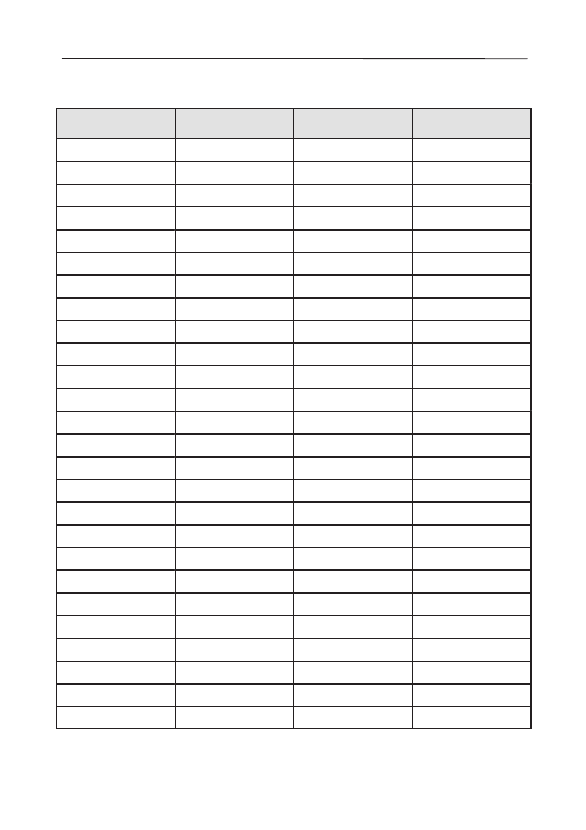
Parts List of AL4 Code: 0200315
ITEM CODE DESCRIPTION VALUE TYPE
R100 1413603 Chip resistor 47 k 5 % 0.063 W 0805
R106 1412286 Jumper 0805
R117 1413829 Chip resistor 10 5 % 0.063 W 0805
R130 1413603 Chip resistor 47 k 5 % 0.063 W 0805
R131 1412310 Chip resistor 470 5 % 0.063 W 0805
R132 1414029 Chip resistor 3.3 k 5 % 0.063 W 0805
R133 1412310 Chip resistor 470 5 % 0.063 W 0805
R134 1410419 Melf resistor 47 5 % 2 W 5.2x17.9
R135 1412430 Chip resistor 10 k 5 % 0.063 W 0805
R136 1413603 Chip resistor 47 k 5 % 0.063 W 0805
R138 1413723 Chip resistor 470 k 5 % 0.063 W 0805
R140 1413635 Chip resistor 100 k 5 % 0.063 W 0805
R141 1414533 Chip resistor 56 k 1 % 0.063 W 0805
R142 1413723 Chip resistor 470 k 5 % 0.063 W 0805
R143 1414526 Chip resistor 120 k 1 % 0.063 W 0805
R144 1414283 Chip resistor 100 k 1 % 0.063 W 0805
R145 1412609 Chip resistor 27 k 5 % 0.063 W 0805
R146 1413723 Chip resistor 470 k 5 % 0.063 W 0805
R147 1413635 Chip resistor 100 k 5 % 0.063 W 0805
R148 1413723 Chip resistor 470 k 5 % 0.063 W 0805
R149 1414029 Chip resistor 3.3 k 5 % 0.063 W 0805
R150 1414029 Chip resistor 3.3 k 5 % 0.063 W 0805
R151 1413635 Chip resistor 100 k 5 % 0.063 W 0805
R152 1413924 Chip resistor 220 5 % 0.063 W 0805
R153 1413924 Chip resistor 220 5 % 0.063 W 0805
R154 1414029 Chip resistor 3.3 k 5 % 0.063 W 0805
R155 1414029 Chip resistor 3.3 k 5 % 0.063 W 0805
R156 1414029 Chip resistor 3.3 k 5 % 0.063 W 0805
R157 1414029 Chip resistor 3.3 k 5 % 0.063 W 0805
R158 1413603 Chip resistor 47 k 5 % 0.063 W 0805
R160 1413603 Chip resistor 47 k 5 % 0.063 W 0805
R161 1412430 Chip resistor 10 k 5 % 0.063 W 0805
R162 1413924 Chip resistor 220 5 % 0.063 W 0805
R163 1414244 Chip resistor 2.2 M 5 % 0.063 W 0805
R164 1414244 Chip resistor 2.2 M 5 % 0.063 W 0805
R170 1414533 Chip resistor 56 k 1 % 0.063 W 0805
R171 1414477 Chip resistor 12.0 k 1 % 0.063 W 0805
R172 1413723 Chip resistor 470 k 5 % 0.063 W 0805
R180 1413603 Chip resistor 47 k 5 % 0.063 W 0805
R181 1414029 Chip resistor 3.3 k 5 % 0.063 W 0805
R182 1412310 Chip resistor 470 5 % 0.063 W 0805
R183 1412310 Chip resistor 470 5 % 0.063 W 0805
C102 2604209 Tantalum cap. 1.0 µ 20 % 16 V 3.2x1.6x1.8
Original 26/97 Page 10
Page 11

PAMS
NHB–3
Technical Documentation
C103 2307816 Ceramic cap. 47 n 20 % 25 V 0805
C104 2307816 Ceramic cap. 47 n 20 % 25 V 0805
C114 2310777 Ceramic cap. 22 n 20 % 50 V 0805
C140 2307816 Ceramic cap. 47 n 20 % 25 V 0805
C141 2307816 Ceramic cap. 47 n 20 % 25 V 0805
C142 2307816 Ceramic cap. 47 n 20 % 25 V 0805
C143 2307816 Ceramic cap. 47 n 20 % 25 V 0805
C150 2307816 Ceramic cap. 47 n 20 % 25 V 0805
C151 2310343 Ceramic cap. 22 p 5 % 50 V 0805
C152 2310343 Ceramic cap. 22 p 5 % 50 V 0805
C153 2604209 Tantalum cap. 1.0 µ 20 % 16 V 3.2x1.6x1.8
C154 2307816 Ceramic cap. 47 n 20 % 25 V 0805
C155 2310738 Ceramic cap. 4.7 n 20 % 50 V 0805
C160 2307816 Ceramic cap. 47 n 20 % 25 V 0805
C161 2604209 Tantalum cap. 1.0 µ 20 % 16 V 3.2x1.6x1.8
C170 2307816 Ceramic cap. 47 n 20 % 25 V 0805
B150 4500685 Crystal 4.8000 M CL30PF h=3.6 mm
V104 4108639 Diode x 2 BAS28 75 V 250 mA SOT143
V114 4100221 Schottky diode 21DQ06 60 V 1.7 A d=3.7x7 mm
V130 4210020 Transistor BCP69–25 pnp 20 V SOT223
V131 4100221 Schottky diode 21DQ06 60 V 1.7 A d=3.7x7 mm
V132 4200917 Transistor BC848B/BCW32 npn 30 V 100 mA SOT23
V134 4200226 Darl. transistor BCV27 npn 30 V 300 mA SOT23
V140 4100567 Sch. diode x 2 BAS70–04 70 V 15 mA SERSOT23
V141 4106992 Zener diode BZX84 5 % 8.2 V 0.3 W SOT23
V150 4102974 Led Green/Red 2.1 V 2x5 mm
V151 4102974 Led Green/Red 2.1 V 2x5 mm
V152 4200917 Transistor BC848B/BCW32 npn 30 V 100 mA SOT23
V153 4200917 Transistor BC848B/BCW32 npn 30 V 100 mA SOT23
V154 4200917 Transistor BC848B/BCW32 npn 30 V 100 mA SOT23
V155 4200917 Transistor BC848B/BCW32 npn 30 V 100 mA SOT23
V160 4200917 Transistor BC848B/BCW32 npn 30 V 100 mA SOT23
V162 4200917 Transistor BC848B/BCW32 npn 30 V 100 mA SOT23
V170 4100567 Sch. diode x 2 BAS70–04 70 V 15 mA SERSOT23
V180 4210020 Transistor BCP69–25 pnp 20 V SOT223
V181 4200917 Transistor BC848B/BCW32 npn 30 V 100 mA SOT23
D150 4340068 IC, ROM MCU16/8 QFP64
N100 4301062 IC, regulator LP2951AC SO8S
N140 4309576 IC, 2 x op.amp. TLC27M2I SO8
S130 5200116 Bush button switch 1–lock 1–pole
X110 9510041 Ph.conn.spring 4D21402 DCH–2
X111 9510041 Ph.conn.spring 4D21402 DCH–2
X120 9510040 Bat.conn.spring 4D21401 DCH–2
X121 9510040 Bat.conn.spring 4D21401 DCH–2
X122 9510040 Bat.conn.spring 4D21401 DCH–2
X123 9510040 Bat.conn.spring 4D21401 DCH–2
X130 5407088 DC connector d=4.5/3.8
Cigarette Lighter Charger LCH–2
Original 26/97 Page 11
Page 12

PAMS
NHB–3
Technical Documentation
9460032 Led holder 3D21400 DCH–2
9853825 PC board AD4A 70x103x1.6 d 2/pa
Cigarette Lighter Charger LCH–2
Original 26/97 Page 12
Page 13

PAMS
NHB–3
Technical Documentation
Exploded View
Cigarette Lighter Charger LCH–2
Assembly Parts
ITEM Q’TY CODE DESCRIPTION VALUE, TYPE
1 9450050 Cover 1D 21289
2 9450051 Bottom 1D 21288
3 9450052 Head–screw 3D 21287
4 9500005 Head–pin 4D 21390
5 6400056 Connector spring 4D 21391
6 3 6154430 PT–screw 25 x 8 WN–1442
7 9370095 Type label 4D 21487
8 7100408 Spiral cable 3D 21247
9 5112050 Fuse 3.15 A/250 V 6.3 x 32 mm
C1 0200044 AL4 module
Original 26/97 Page 13
Page 14

PAMS
NHB–3
Technical Documentation
Cigarette Lighter Charger LCH–2
This page intentionally left blank.
Original 26/97 Page 14
 Loading...