

Page 1

Programme’s After Market Services
NHD–4 Series Transceivers
CAR Installation
Guide
Original 11/97
Page 2

NHD–4
PAMAS
CAR Installation Guide
Technical Documentation
CONTENTS
Installation Instructions 3. . . . . . . . . . . . . . . . . . . . . . . . . . . . . . . . . . . . . . . . . . . .
Mobile Handsfree Car Kit Installation (CARK–11) 3. . . . . . . . . . . . . . . . . .
Product List 4. . . . . . . . . . . . . . . . . . . . . . . . . . . . . . . . . . . . . . . . . . . . . . .
Mobile HF Charging Holder (MCH–8) 4. . . . . . . . . . . . . . . . . . . . . . . . .
Mounting Plate and Swivel (MKE–1 and HHS–1) 4. . . . . . . . . . . . . . .
Junction Box (HFJ–3) 4. . . . . . . . . . . . . . . . . . . . . . . . . . . . . . . . . . . . . . .
Power Cable (PCH–4) 4. . . . . . . . . . . . . . . . . . . . . . . . . . . . . . . . . . . . . .
Handsfree Microphone and Speaker (HFM–4 and HFS–6) 4. . . . . . .
Car Radio Mute (XCRM) 5. . . . . . . . . . . . . . . . . . . . . . . . . . . . . . . . . . . .
Ignition Sense (IGNS) 5. . . . . . . . . . . . . . . . . . . . . . . . . . . . . . . . . . . . . . .
Handset (HSU–1) 5. . . . . . . . . . . . . . . . . . . . . . . . . . . . . . . . . . . . . . . . . .
Modular 8 Pin Extension Cable (SCE–4) 6. . . . . . . . . . . . . . . . . . . . . .
Fixed & Compact HF Holder Installation 6. . . . . . . . . . . . . . . . . . . . . . . . .
Product List 7. . . . . . . . . . . . . . . . . . . . . . . . . . . . . . . . . . . . . . . . . . . . . . .
Mounting Plate and Swivel (MKE–1 and HHS–1) 7. . . . . . . . . . . . . . .
Compact HF Holder (PHF–1) 7. . . . . . . . . . . . . . . . . . . . . . . . . . . . . . . .
Cigarette Lighter Cable (LCP–2, CARK–10 only) 7. . . . . . . . . . . . . . .
Power Cable (PCN–5, CARK–16 only) 8. . . . . . . . . . . . . . . . . . . . . . . .
Handsfree Microphone (HFM–4) 8. . . . . . . . . . . . . . . . . . . . . . . . . . . . .
Mobile Holder (MBH–6) 8. . . . . . . . . . . . . . . . . . . . . . . . . . . . . . . . . . . . .
Page 2
Original 11/97
Page 3
PAMS
NHD–4
Technical Documentation
Installation Instructions
This manual aims to give the required information for installing the
handheld telephone into a vehicle. The installer should rely on his or her
own skills and common sense when choosing the locations. The end user
should never attempt to install the telephone without professional
assistance as the install requires special tools and knowledge. The terms
of warranty demands that the telephone is installed by an experienced
installation facility.
The system cable routing isn’t usually critical; however it should not be
routed next to electronic ignition systems or ABS braking systems wires or
boxes to prevent interference to important automotive electrical
components.
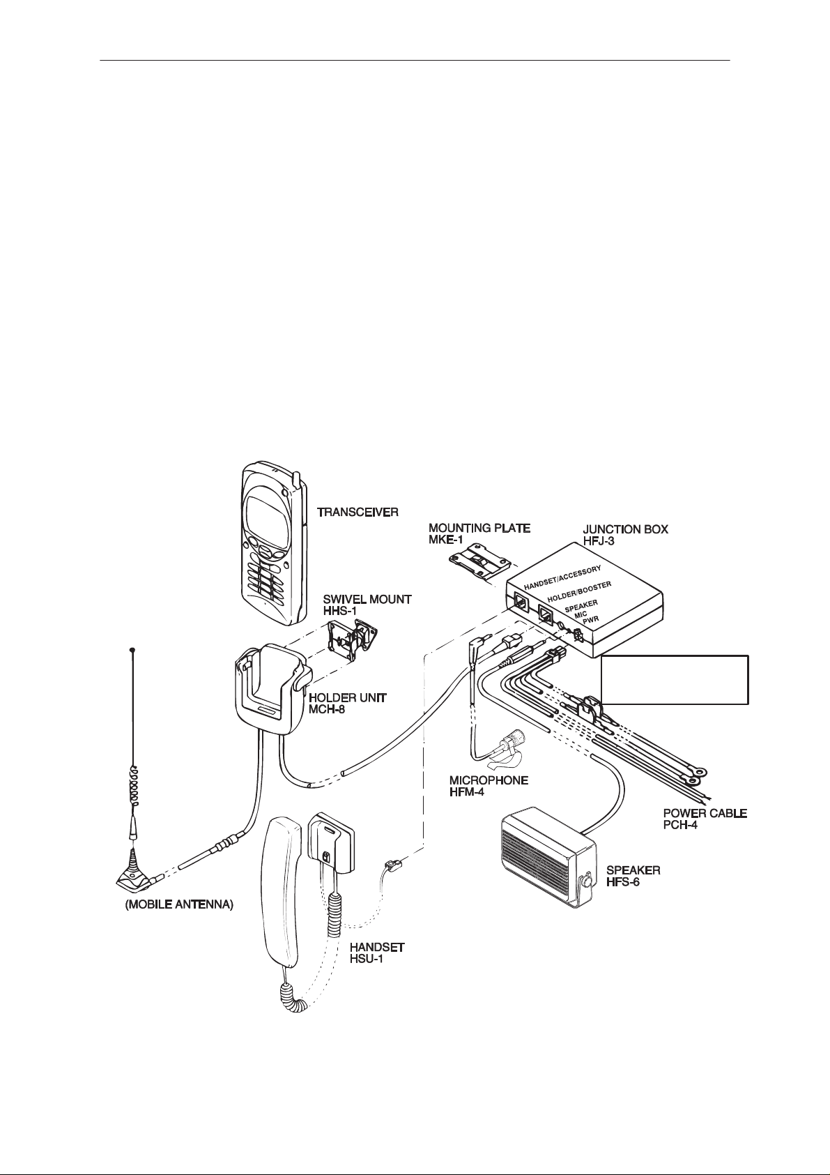
Mobile Handsfree Car Kit Installation (CARK–11)
CAR Installation Guide
Not supplied !
RED = + BATT 12 V
BLACK = – BATT GROUND
BLUE = IGNITION SENSE
YELLOW = RADIO MUTE
Original 11/97
Page 3
Page 4

NHD–4
PAMAS
CAR Installation Guide
Product List
Product: Remarks: Code:
Mobile HF charging holder MCH–8
HF junction box HFJ–3
Mounting plate (w/16 screws) MKE–1
Swivel mount (w/6 screws) HHS–1
HF microphone (w/flat mounting plate) HFM–4
HF loudspeaker (w/2 fused conn. & wire ends) PCH–4
Power cable LCP–1
Handset option (optional) HSU–1
Modular 8 pin extension cable SCE–4
Mobile HF Charging Holder (MCH–8)
The holder unit MCH–8 offers an external antenna connection, handsfree
and also firm attachment to the vehicle.
Mounting Plate and Swivel (MKE–1 and HHS–1)
Technical Documentation
The mounting plate (MKE–1) and swivel mount (HHS–1) mounting
brackets are interchangeable. Either one can be used to mount the
MCH–8 or HFJ–3. The MKE–1 mounts flat and HHS–1 swivels for
adjustable mounting angles.
Junction Box (HFJ–3)
Handsfree junction box (HFJ–3) provides and controls the supply voltages
for the accessories and charge current for the handportable. In addition, it
controls the audio paths to accessories and handsfree equipment. The
jack marked HANDSET/ACCESSORY is reserved for the optional
handset.
Power Cable (PCH–4)
The power cable connects to the junction box (HFJ–3) via the 4 pin
connector. The red (+12V) and black (GND) wires connect to the battery
via the supplied fused connectors. The yellow (XCRM) wire is for car radio
mute and the blue (IGNS) wire is for ignition sense. The XCRM line goes
down to 0 volts during a call. The maximum sink current is 250 mA, (see
”CAR RADIO MUTING”). The IGNS line is connected to a +12 V voltage
source, controlled by the car ignition key. The ignition sense can utilize
voltages up to 24 V, (see ”IGNITION SENSE”).
Handsfree Microphone and Speaker (HFM–4 and HFS–6)
The handsfree microphone can usually be installed on the drivers sunvisor
or A–pillar. The main idea is to get the microphone as close to the driver’s
mouth as possible, and to attach the microphone to a surface that is
mechanically quiet. The microphone connects to the HFJ–3 MIC jack. The
loudspeaker should be mounted at least 3 ft/1 m away from the handsfree
mic to avoid acoustic feedback. The loudspeaker connects to the HFJ–3
SPEAKER jack.
Page 4
Original 11/97
Page 5

PAMS
NHD–4
Technical Documentation
Car Radio Mute (XCRM)
The phone offers a feature that can mute the car radio automatically
during a conversation. This feature is convenient and provides for safer
handsfree operation. The car radio muting feature based on grounded
line, so it means that in standby, the yellow wire (XCRM) is not grounded
and car radio works normally, but during a call, line is grounded and car
radio is muted. The maximum load that this line can handle is 250 mA.
Note that an auxiliary relay or muting unit must be used when the car
radio doesn’t have a mute feature available.
When a relay is used, it is connected in
series with the car radio main supply.
A 200 mA fuse should be used to
protect the XCRM output
in event ofa short circuit.
Some radios have separate
supplies for amplifiers and
motors, and another for memory
backup purposes. Very often these
radios also have a secret code
system, which activates itself
if a break in the memory supply
is detected. Be careful when installing
the relay not to break the memory supply (usually markedACC or +MEM),
but to install the relay in the main supply feed.
CAR
RADIO
T o XCRM line
(PCH–4/yello
w)
87A
CAR Installation Guide
Bosch P/N
0–332–204–150
12 V, 30 A. SPDT
30
87
85
Supply for
car radio
86
Fuse 200 mA
(not
supplied)
12 V d.c.
12 V d.c.
Another possibility is to use a special muting unit (SR59), which mutes the
radio by connecting load resistors to the speaker lines of the car radio.
Four loudspeakers can be muted and the maximum permitted power is 20
watts per channel. The muting unit can also be used as a relay to cut the
main supply feed of the car radio.
Ignition Sense (IGNS)
The ignition sense feature prevents the transceiver from draining the car
battery by executing an auto power off 20 seconds after the ignition key
has been turned off. The blue wire of the power cable is used for the
ignition sense feature. The use of IGNITION SENSE is recommended to
prevent accidental draining of the car’s battery. The wire is connected via
a 200 mA fuse to a 12/24 volts potential that is controlled by the ignition
key. Do not connect it directly to the high voltage sections of the ignition
circuit.
Handset (HSU–1)
An optional handset offers more privacy during the call. The holder is
attached with mounting plate MKE–1 or swivel HHS–1.
Original 11/97
Page 5
Page 6

NHD–4
PAMAS
CAR Installation Guide
Modular 8 Pin Extension Cable (SCE–4)
This cable provides an extension between the HFJ–3 and MCH–8.
SCE–4
Fixed & Compact HF Holder Installation
Technical Documentation
Page 6
(CARK–10 only)
Not supplied !
Original 11/97
Page 7

PAMS
NHD–4
Technical Documentation
Product List
Product: Remarks: Code:
Mobile holder MBH–6
Compact HF holder (w/cradle adapter) PHF–1
Mounting plate (w/12 screws, 4 nuts, 4 wash.) MKE–1
Swivel mount (w/6 screws) HHS–1
HF microphone HFM–4
Cigarette lighter cable (CARK–10 only) LCP–2
Power cable (CARK–16 only) PCH–5
Cradle adapter MKE–4N
Cable holder CKH–1
Mounting Plate and Swivel (MKE–1 and HHS–1)
The mounting plate (MKE–1) and swivel mount (HHS–1) mounting
brackets are interchangeable. Either one can be used to mount the
PHF–1 or MBH–6.The MKE–1 mounts flat and HHS–1 swivels for
adjustable mounting angles. NOTE ! MKE–1 is not directly
interchangeable with the cradle adapter MKE–4N.
CAR Installation Guide
Compact HF Holder (PHF–1)
Compact HF holder (PHF–1) provides and controls the supply voltage and
charge current for the handportable. In addition, it controls the audio paths
to handsfree equipment, and provides external antenna connection
(mini–UHF).
Cigarette Lighter Cable (LCP–2, CARK–10 only)
The cigarette lighter cable connects to the compact HF holder (PHF–1) via
the 5.5 mm d.c. plug. The other connector in the cable is plugged to the
standard cigarette lighter jack of the vehicle. Supply voltage may vary
between 10,8 and 15.6 volts.
CAUTION !
Maximum supply voltage is 15.6 volts, minus (–) in the chassis of the
vehicle !
Overvoltage or wrong polarity may cause serious
damage to the car kit !
Original 11/97
Page 7
Page 8

NHD–4
PAMAS
CAR Installation Guide
Power Cable (PCN–5, CARK–16 only)
The power cable connects to the compact HF holder via the 5.5 mm d.c.
plug. The red (+12V) and black (GND) wires connect to the battery via the
supplied fused connectors. Supply voltage may vary between 10.8 and
15.6 volts.
CAUTION !
Maximum supply voltage is 15.6 volts, minus (–) in the chassis of the
vehicle !
Overvoltage or wrong polarity may cause serious
damage to the car kit !
Handsfree Microphone (HFM–4)
The handsfree microphone can usually be installed on the drivers sunvisor
or A–pillar. The main idea is to get the microphone as close to the driver’s
mouth as possible, and to attach the microphone to a surface that is
mechanically quiet. The microphone connects to the corresponding 2.5
mm jack in the PHF–1.
Technical Documentation
Mobile Holder (MBH–6)
The holder unit MBH–6 offers firm attachment. It is usually attached to
Compact HF Holder PHF–1 with the Cradle Adapter Kit (MKE–4N), which
includes the cradle adapter, 4 screws and 4 nuts.To attach the MBH–6 to
the PHF–1 first you have to remove the lower cover of PHF–1 by
detaching the four crossheaded screws visible underneath the PHF–1
(Figures 1, 2). Insert the four provided nuts into the corresponding slots in
the cradle adapter MKE–4N, and slide the cradle adapter into its place
underneath the MBH–6 (Figure 3). Do not use mounting plate MKE–1 in
place of cradle adapter MKE–4N. Mount MBH–6 to its slot in the front part
of PHF–1, and finally attach it by using the provided screws (Figures 4, 5).
It is also possible to use the MBH–6 as a separate mobile holder, it is then
attached to the vehicle with MKE–1 or HHS–1.
Page 8
Original 11/97
Page 9

PAMS
NHD–4
Technical Documentation
FIG 1 FIG 2
CAR Installation Guide
FIG 3 FIG 4
FIG 5
Original 11/97
Page 9
Page 10

NHD–4
PAMAS
CAR Installation Guide
Technical Documentation
[This page intentionally left blank]
Page 10
Original 11/97
 Loading...