

Page 1

After Sales Technical Documentation
NHD–4 Series Transceivers
Service Tools
Original 11/97
Page 2

NHD–4
PAMS
Service Tools
Technical Documentation
CONTENTS
Phone and Service Accessories Connections 3. . . . . . . . . . . . . . . . . . . . . . . .
MBUS Link 3. . . . . . . . . . . . . . . . . . . . . . . . . . . . . . . . . . . . . . . . . . . . . . . . . . .
Equipment Setup For Tuning A Phone With Covers 4. . . . . . . . . . . . . . . .
Equipment Setup For Tuning A Phone Without covers 5. . . . . . . . . . . . .
Service Accessories 6. . . . . . . . . . . . . . . . . . . . . . . . . . . . . . . . . . . . . . . . . . . . . .
Audio Cable ADS–1 6. . . . . . . . . . . . . . . . . . . . . . . . . . . . . . . . . . . . . . . . . . .
Power Connector PCS–1 6. . . . . . . . . . . . . . . . . . . . . . . . . . . . . . . . . . . . . . .
PC/MBUS Adapter DAU–2 7. . . . . . . . . . . . . . . . . . . . . . . . . . . . . . . . . . . . .
SW Security Device ”Dongle” PKD–1 7. . . . . . . . . . . . . . . . . . . . . . . . . . . .
Dummy Battery Pack BTS–4 8. . . . . . . . . . . . . . . . . . . . . . . . . . . . . . . . . . . .
Service Cable SCS–1 8. . . . . . . . . . . . . . . . . . . . . . . . . . . . . . . . . . . . . . . . . .
Service Cable SCS–3 9. . . . . . . . . . . . . . . . . . . . . . . . . . . . . . . . . . . . . . . . . .
RF Adapter to Top Antenna Connector 9. . . . . . . . . . . . . . . . . . . . . . . . . . .
Battery Adapter BDS–2 10. . . . . . . . . . . . . . . . . . . . . . . . . . . . . . . . . . . . . . . .
Test Frame JBS–8 10. . . . . . . . . . . . . . . . . . . . . . . . . . . . . . . . . . . . . . . . . . . . .
Service Box JBS–7 11. . . . . . . . . . . . . . . . . . . . . . . . . . . . . . . . . . . . . . . . . . . .
Flash Prommer FPS–3C 12. . . . . . . . . . . . . . . . . . . . . . . . . . . . . . . . . . . . . . .
Modular Cable XCM–1 13. . . . . . . . . . . . . . . . . . . . . . . . . . . . . . . . . . . . . . . . .
Modular T–Adapter 13. . . . . . . . . . . . . . . . . . . . . . . . . . . . . . . . . . . . . . . . . . . .
D9/D25 RS–232 Adapter 14. . . . . . . . . . . . . . . . . . . . . . . . . . . . . . . . . . . . . . .
Page 2
Original 11/97
Page 3
PAMS
NHD–4
Technical Documentation
Service Tools
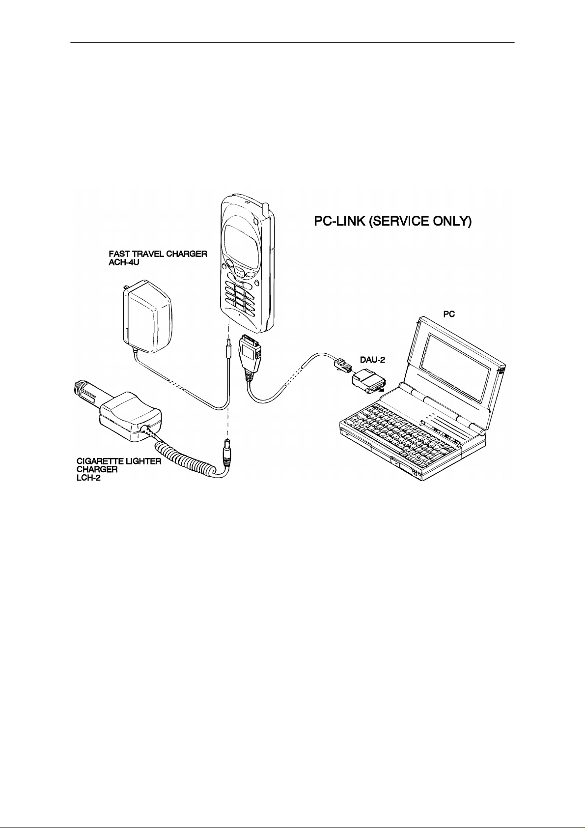
Phone and Service Accessories Connections
MBUS Link
Original 11/97
Page 3
Page 4
NHD–4
PAMS
Service Tools
Technical Documentation
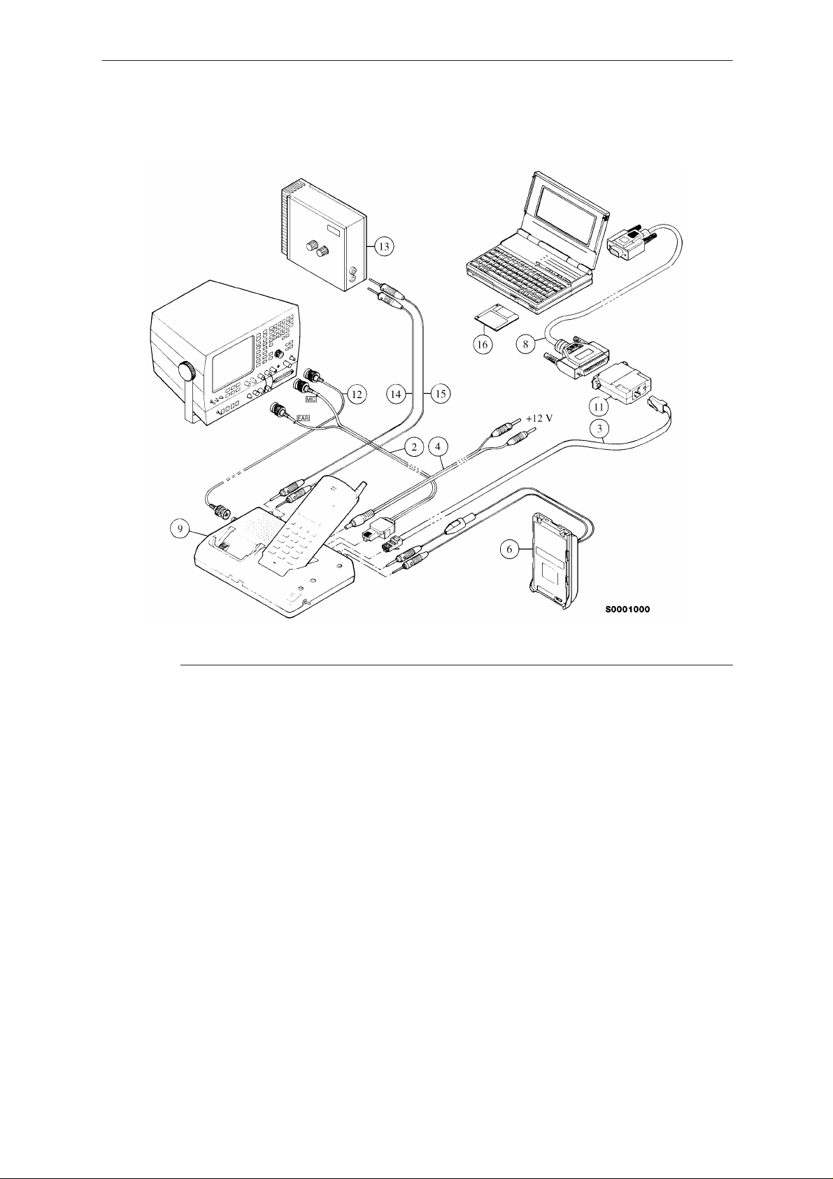
Equipment Setup For Tuning A Phone With Covers
Item: Service accessory: Product code:
2 Audio cable, ADS–1 0730011
3 Modular cable, XCM–1 4626131
4 Power Connector, PCS–1 0730012
6 Dummy battery, BTS–4 0770009
8 RS–232 adapter (9 pin to 25 pin) 4626170
9 Service box, JBS–7 0770015
11 PC/M2BUS adapter, DAU–2 0750006
12 BCN cable (not available)
13 Battery tester BT–20 4626146
14 Banana cable (not available)
15 Banana cable (not available)
16 Service Software diskette 3.5”, 0067261
– Software protection key, PKD–1 0750018
Page 4
Original 11/97
Page 5
PAMS
NHD–4
Technical Documentation
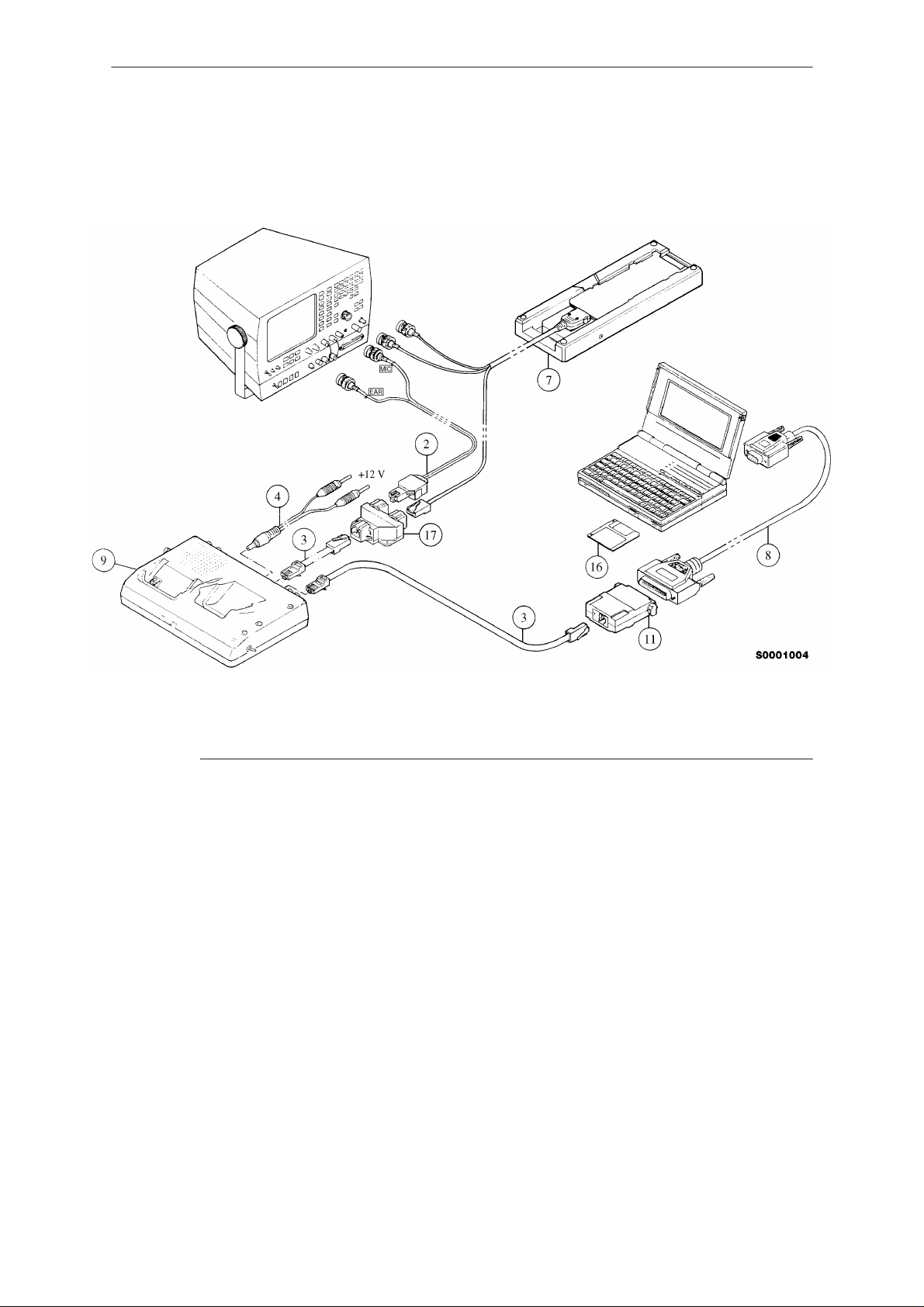
Equipment Setup For Tuning A Phone Without covers
Service Tools
Item: Service accessory: Product code:
2 Audio cable, ADS–1 0730011
3 Modular cable, XCM–1 4626131
4 Power connector, PCS–1 0730012
7 Test frame, JBS–8 0770014
8 RS–232 adapter (9 pin to 25 pin) 4626170
9 Service box, JBS–7 0770015
11 PC/M2BUS adapter, DAU–2 0750006
16 Wintesla diskette 3.5”, 0067261
17 Modular T–connector 4626134
– Software protection key PKD–1 0750018
Original 11/97
Page 5
Page 6

NHD–4
PAMS
Service Tools
Service Accessories
Audio Cable ADS–1
Product code: 0730011
Technical Documentation
Audio cable is an adapter routing AF signals (MIC/EAR) from 8 pin
modular connector to two BNC connectors.
Power Connector PCS–1
Product code: 0730012
Suitable adapter between JBS–7 and the power supply.
Page 6
Original 11/97
Page 7

PAMS
NHD–4
Technical Documentation
PC/MBUS Adapter DAU–2
Product code: 0750006
DAU–2 is connected between the phone and the serial (COM) port of the
PC. It matches the M2BUS data bus signals to the serial data bus of the
computer.
SW Security Device ”Dongle” PKD–1
Service Tools
Product code: 0750018
SW security device ”Dongle” is a piece of hardware enabling the use of
the PCLocals when connected to the parallel (LPT) port of the PC.
Whitout the dongle present it is not possible to use the service SW. Printer
or any such device can be connected to the PC through the dongle if
needed.
Caution: Make sure that you have switched off the PC and the printer
before making connections!
Caution: Do not connected the PKD–1 to the serial port. You may
damage your PKD–1!
Original 11/97
Page 7
Page 8

NHD–4
PAMS
Service Tools
Dummy Battery Pack BTS–4
Product code: 0770009
Technical Documentation
Dummy battery is convenient device when the battery reference voltage is
to be programmed. JBS–7 has a voltage setting for supplying specified
reference voltage needed for this programming. Of course the BTS can be
used to substitute the normal battery also during normal testing, and
optionally the input d.c. may be taken from some external power supply.
However, one should take care not to exceed the voltage rating of the
phone.
Service Cable SCS–1
Product code: 0770010
Page 8
Service cable SCS–1 is an adapter routing RF signal(s) from phone
bottom connector to two BNC connectors. It also contains modular
connector that can be used to service purposes.
Original 11/97
Page 9

PAMS
NHD–4
Technical Documentation
RF Adapter to Top Antenna Connector
Product code: 0770011
Service Tools
AAS–3 provides a connection from top antenna connector to the
measurement device. The accuracy of the connection is not as good as with
bottom antenna connector.
Original 11/97
Page 9
Page 10

NHD–4
PAMS
Service Tools
Battery Adapter BDS–2
Product code: 0770013
Battery adapter is used when the condition of the battery pack is to be
tested with either internal discharging feature, or with external capacity
meter. It provides a suitable mechanical interface for charging and
discharging.
Technical Documentation
Test Frame JBS–8
Product code: 0770014
Page 10
JBS–8 is used when the service work must be done without covers in the
phone.
Original 11/97
Page 11

PAMS
NHD–4
Technical Documentation
The phone’s radio module is placed into plastic frame, which provides the
needed connections to the bottom– and battery connectors of the phone.
RF connection is done by RF cable, which is as well included into the
JBS–8.
Suitable d.c. power supply regulation for JBS–8 concept is provided by
example JBS–7. Note, that the UI module (flex) is not required in this
environment. Note also, that some of the signal values give wrong results
when RF shields are removed. Hence the phone should never be tuned
without the shields.
Service Box JBS–7
Product code: 0770015
Service Tools
Service box provides convenient test environment (regulated power
supply, M2BUS, preset battery reference voltage, external RF connection,
audio test loops, HOOK switch etc.) and mechanical interface in one box.
When AUDIO switch of JBS–7 is INT position, the AF signals are routed
normally to the modular–type system connectors. When in EXT position,
the AF signals are routed from the speaker pin of the bottom connector
straight back to the external microphone pin of the phone. Thus the
speech codec of the phone is able to feed the internally generated test
signal to the loudspeaker line, and measure the same signal from the EXT
MIC line. Whenever audio signals are to be monitored or measured
outside the phone, the AUDIO switch of the JBS–7 must be in INT
position.
HOOK switch of the JBS–7 enables the audio signals to be routed to and
from the phone via the bottom connector also when the phone is in
cellular mode, for example during a test call to some cellular tester. When
HOOK switch is in OFF position and the phone in cellular mode, the
audios are always routed to earpiece and internal microphone.
Additionally JBS–7 has a spare battery slot, though which the battery may
be connected to external capacity meter.
Original 11/97
Page 11
Page 12

NHD–4
PAMS
Service Tools
Note: When tuning the NHC–1 analog mode maximum power, do not use
more than 10 volts d.c. in the power supply input of the JBS–7.
Flash Prommer FPS–3C
Product code: 0770110
Flash Programming Set: 0271330
Technical Documentation
FLASH prommer is used to update the main software of the phone, should
that some day become necessary. Updating is done by first loading the new
MCU software from PC to the FLASH prommer and then loading the new
SW from prommer to the phone. When updating more than one phone in a
row, the new MCU SW must be loaded to the prommer only in the
beginning.
Service software (called also Wintesla) is used to control the functions of
the phone with IBM PC/AT/–386/–486/–586 or compatible personal
computer during the service work.
Page 12
Original 11/97
Page 13

PAMS
NHD–4
Technical Documentation
Modular Cable XCM–1
Product code: 4626131
XCM–1 is a standard 1 meter long flat cable with male modular–8
connectors in both ends. In a complete service concept three pieces of the
XCM–1 is needed.
Service Tools
Modular T–Adapter
Product code: 4626134
Modular T–adapter is suitable branching unit to provide the needed
parallel modular connections.
Original 11/97
Page 13
Page 14

NHD–4
PAMS
Service Tools
D9/D25 RS–232 Adapter
Product code: 4626170
Suitable adapter between DAU–2 and computers having 9 pin D
connector as a serial port.
Technical Documentation
Page 14
Original 11/97
 Loading...