

Page 1

Programme’s After Market Services
Tesla For Windows
WinTesla User Guide
Page 2

WinTesla User Guide
PAMS
NHD–4
Technical Documentation
CONTENTS –
Page No
Tesla for Windows Operating System 5. . . . . . . . . . . . . . . . . . . . . . . . . . . . . . .
Installing WinTesla On Your Hard Disk 5. . . . . . . . . . . . . . . . . . . . . . . . . . . . . .
Using The Windows Interface 5. . . . . . . . . . . . . . . . . . . . . . . . . . . . . . . . . . . . . .
Common User Interface 6. . . . . . . . . . . . . . . . . . . . . . . . . . . . . . . . . . . . . . . . . . .
Equipment Required 6. . . . . . . . . . . . . . . . . . . . . . . . . . . . . . . . . . . . . . . . . . . . . .
Mechanical Connections 6. . . . . . . . . . . . . . . . . . . . . . . . . . . . . . . . . . . . . . . . . .
Using Wintesla 8. . . . . . . . . . . . . . . . . . . . . . . . . . . . . . . . . . . . . . . . . . . . . . . . . . .
Phone Independence 8. . . . . . . . . . . . . . . . . . . . . . . . . . . . . . . . . . . . . . . . . .
Login ID Setup 9. . . . . . . . . . . . . . . . . . . . . . . . . . . . . . . . . . . . . . . . . . . . . . . .
The Login Screen 10. . . . . . . . . . . . . . . . . . . . . . . . . . . . . . . . . . . . . . . . . . . . .
The WinTesla Screen 11. . . . . . . . . . . . . . . . . . . . . . . . . . . . . . . . . . . . . . . . . .
The Product Menu 11. . . . . . . . . . . . . . . . . . . . . . . . . . . . . . . . . . . . . . . . . . . . .
The Configure Menu 13. . . . . . . . . . . . . . . . . . . . . . . . . . . . . . . . . . . . . . . . . . .
1. Fault Log Application. 17. . . . . . . . . . . . . . . . . . . . . . . . . . . . . . . . . . . . . . . .
Help 21. . . . . . . . . . . . . . . . . . . . . . . . . . . . . . . . . . . . . . . . . . . . . . . . . . . . . . . . .
HD881 Module 22. . . . . . . . . . . . . . . . . . . . . . . . . . . . . . . . . . . . . . . . . . . . . . . . . . .
Installing the HD881 Service Module 22. . . . . . . . . . . . . . . . . . . . . . . . . . . . . . . .
Required Servicing Equipment 22. . . . . . . . . . . . . . . . . . . . . . . . . . . . . . . . . .
Equipment Setup 23. . . . . . . . . . . . . . . . . . . . . . . . . . . . . . . . . . . . . . . . . . . . . .
Dealer Setups 24. . . . . . . . . . . . . . . . . . . . . . . . . . . . . . . . . . . . . . . . . . . . . . . .
Main Menu 26. . . . . . . . . . . . . . . . . . . . . . . . . . . . . . . . . . . . . . . . . . . . . . . . . . .
Product 26. . . . . . . . . . . . . . . . . . . . . . . . . . . . . . . . . . . . . . . . . . . . . . . . . . . . . .
Configure 26. . . . . . . . . . . . . . . . . . . . . . . . . . . . . . . . . . . . . . . . . . . . . . . . . . . .
Tuning Steps of Radio Unit 27. . . . . . . . . . . . . . . . . . . . . . . . . . . . . . . . . . . . . . . .
Accuracy of the Equipment During Measurement 27. . . . . . . . . . . . . . . . . .
General 28. . . . . . . . . . . . . . . . . . . . . . . . . . . . . . . . . . . . . . . . . . . . . . . . . . . . . . . . .
Battery Voltage Adjustment 28. . . . . . . . . . . . . . . . . . . . . . . . . . . . . . . . . . . . .
Charge Voltage Adjustment 28. . . . . . . . . . . . . . . . . . . . . . . . . . . . . . . . . . . . .
RF Temperature Adjustment 28. . . . . . . . . . . . . . . . . . . . . . . . . . . . . . . . . . . .
AMPS Tuning 29. . . . . . . . . . . . . . . . . . . . . . . . . . . . . . . . . . . . . . . . . . . . . . . . . . . .
Analog Bias Current Tuning 29. . . . . . . . . . . . . . . . . . . . . . . . . . . . . . . . . . . .
AFC Tuning 30. . . . . . . . . . . . . . . . . . . . . . . . . . . . . . . . . . . . . . . . . . . . . . . . . .
Deaf Channel Frequency Tuning 31. . . . . . . . . . . . . . . . . . . . . . . . . . . . . . . .
TX Output Power 32. . . . . . . . . . . . . . . . . . . . . . . . . . . . . . . . . . . . . . . . . . . . . .
TX Modulation Index Calibration 33. . . . . . . . . . . . . . . . . . . . . . . . . . . . . . . . .
RSSI 34. . . . . . . . . . . . . . . . . . . . . . . . . . . . . . . . . . . . . . . . . . . . . . . . . . . . . . . .
Page 2
Original 11/97
Page 3

PAMS
WinTesla User Guide
Technical Documentation
RX Audio Gain 35. . . . . . . . . . . . . . . . . . . . . . . . . . . . . . . . . . . . . . . . . . . . . . . .
CDMA Tuning 36. . . . . . . . . . . . . . . . . . . . . . . . . . . . . . . . . . . . . . . . . . . . . . . . . . . .
RX Offset Tuning – (RX/TX) 36. . . . . . . . . . . . . . . . . . . . . . . . . . . . . . . . . . . .
RX Offset Tuning – (RX) 37. . . . . . . . . . . . . . . . . . . . . . . . . . . . . . . . . . . . . . .
Rx Slope 38. . . . . . . . . . . . . . . . . . . . . . . . . . . . . . . . . . . . . . . . . . . . . . . . . . . . .
Rx Slope Rx 39. . . . . . . . . . . . . . . . . . . . . . . . . . . . . . . . . . . . . . . . . . . . . . . . . .
Rx Gain Switch Calibration 40. . . . . . . . . . . . . . . . . . . . . . . . . . . . . . . . . . . . .
CDMA TX Bias Tuning 41. . . . . . . . . . . . . . . . . . . . . . . . . . . . . . . . . . . . . . . . .
Align TX Gain Limiting Tuning 43. . . . . . . . . . . . . . . . . . . . . . . . . . . . . . . . . . .
Aux. AGC Tuning 44. . . . . . . . . . . . . . . . . . . . . . . . . . . . . . . . . . . . . . . . . . . . . .
AGC Tuning 49. . . . . . . . . . . . . . . . . . . . . . . . . . . . . . . . . . . . . . . . . . . . . . . . . .
T esting 50. . . . . . . . . . . . . . . . . . . . . . . . . . . . . . . . . . . . . . . . . . . . . . . . . . . . . . . . . .
Self Tests 50. . . . . . . . . . . . . . . . . . . . . . . . . . . . . . . . . . . . . . . . . . . . . . . . . . . .
ADC Readings 50. . . . . . . . . . . . . . . . . . . . . . . . . . . . . . . . . . . . . . . . . . . . . . . .
Pulse Division Modulator (PDM) Control 51. . . . . . . . . . . . . . . . . . . . . . . . . .
NHD–4
AMPS / BaseBand Test Screen 52. . . . . . . . . . . . . . . . . . . . . . . . . . . . . . . . .
AMPS Testing 54. . . . . . . . . . . . . . . . . . . . . . . . . . . . . . . . . . . . . . . . . . . . . . . . . . .
AFC Tuning Functionality Test 54. . . . . . . . . . . . . . . . . . . . . . . . . . . . . . . . . .
AFC – Deaf Channel Tuning Functionality Test 54. . . . . . . . . . . . . . . . . . . .
AMPS TX Power Level Tuning Functionality Test 55. . . . . . . . . . . . . . . . . .
AMPS TX Bias Tuning Functionality Test 56. . . . . . . . . . . . . . . . . . . . . . . . .
RSSI Tuning Functionality Test 57. . . . . . . . . . . . . . . . . . . . . . . . . . . . . . . . . .
CDMA Testing 58. . . . . . . . . . . . . . . . . . . . . . . . . . . . . . . . . . . . . . . . . . . . . . . . . . .
CDMA TX Bias Tuing Functionality Test 58. . . . . . . . . . . . . . . . . . . . . . . . . .
TX Gain Limiting Tuning Functionality Test 59. . . . . . . . . . . . . . . . . . . . . . . .
Aux. AGC Tuning Functionality Test 60. . . . . . . . . . . . . . . . . . . . . . . . . . . . .
LNA Gain Calibration Functionality Test 61. . . . . . . . . . . . . . . . . . . . . . . . . .
CDMA TX Spurious Check 61. . . . . . . . . . . . . . . . . . . . . . . . . . . . . . . . . . . . .
LNA Gain Calibration 62. . . . . . . . . . . . . . . . . . . . . . . . . . . . . . . . . . . . . . . . . .
Software Menu 64. . . . . . . . . . . . . . . . . . . . . . . . . . . . . . . . . . . . . . . . . . . . . . . . . . .
Flashing 64. . . . . . . . . . . . . . . . . . . . . . . . . . . . . . . . . . . . . . . . . . . . . . . . . . . . .
Dialog Options 64. . . . . . . . . . . . . . . . . . . . . . . . . . . . . . . . . . . . . . . . . . . . . . . .
Initialize EEPROM 66. . . . . . . . . . . . . . . . . . . . . . . . . . . . . . . . . . . . . . . . . . . . .
Dealer Menu 67. . . . . . . . . . . . . . . . . . . . . . . . . . . . . . . . . . . . . . . . . . . . . . . . . . . . .
NAM Programming 67. . . . . . . . . . . . . . . . . . . . . . . . . . . . . . . . . . . . . . . . . . . .
Short Code Memory (SCM) 69. . . . . . . . . . . . . . . . . . . . . . . . . . . . . . . . . . . . .
SID Programming 70. . . . . . . . . . . . . . . . . . . . . . . . . . . . . . . . . . . . . . . . . . . . .
Calling Cards 71. . . . . . . . . . . . . . . . . . . . . . . . . . . . . . . . . . . . . . . . . . . . . . . . .
Authentication Key (A–Key) Programming 72. . . . . . . . . . . . . . . . . . . . . . . .
Original 11/97
Page 3
Page 4

WinTesla User Guide
PAMS
NHD–4
User Data Transfer 73. . . . . . . . . . . . . . . . . . . . . . . . . . . . . . . . . . . . . . . . . . . .
Set Factory Values 74. . . . . . . . . . . . . . . . . . . . . . . . . . . . . . . . . . . . . . . . . . . .
SPC code change 74. . . . . . . . . . . . . . . . . . . . . . . . . . . . . . . . . . . . . . . . . . . . .
View Menu 75. . . . . . . . . . . . . . . . . . . . . . . . . . . . . . . . . . . . . . . . . . . . . . . . . . . . . .
Phone Identity 75. . . . . . . . . . . . . . . . . . . . . . . . . . . . . . . . . . . . . . . . . . . . . . . .
RF Parameters 76. . . . . . . . . . . . . . . . . . . . . . . . . . . . . . . . . . . . . . . . . . . . . . .
Help 77. . . . . . . . . . . . . . . . . . . . . . . . . . . . . . . . . . . . . . . . . . . . . . . . . . . . . . . . . . . .
Common Problems 78. . . . . . . . . . . . . . . . . . . . . . . . . . . . . . . . . . . . . . . . . . . . . . .
Setting up the computer Hardware 78. . . . . . . . . . . . . . . . . . . . . . . . . . . . . . .
Common Errors 78. . . . . . . . . . . . . . . . . . . . . . . . . . . . . . . . . . . . . . . . . . . . . . .
Service and Support 79. . . . . . . . . . . . . . . . . . . . . . . . . . . . . . . . . . . . . . . . . . . . . .
Technical Documentation
List of Figures–
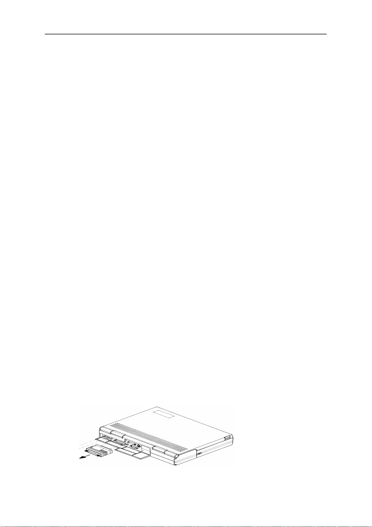
Figure 1. Dongle Insertion 6. . . . . . . . . . . . . . . . . . . . . . . . . . . . . . . . . . . . . . . .
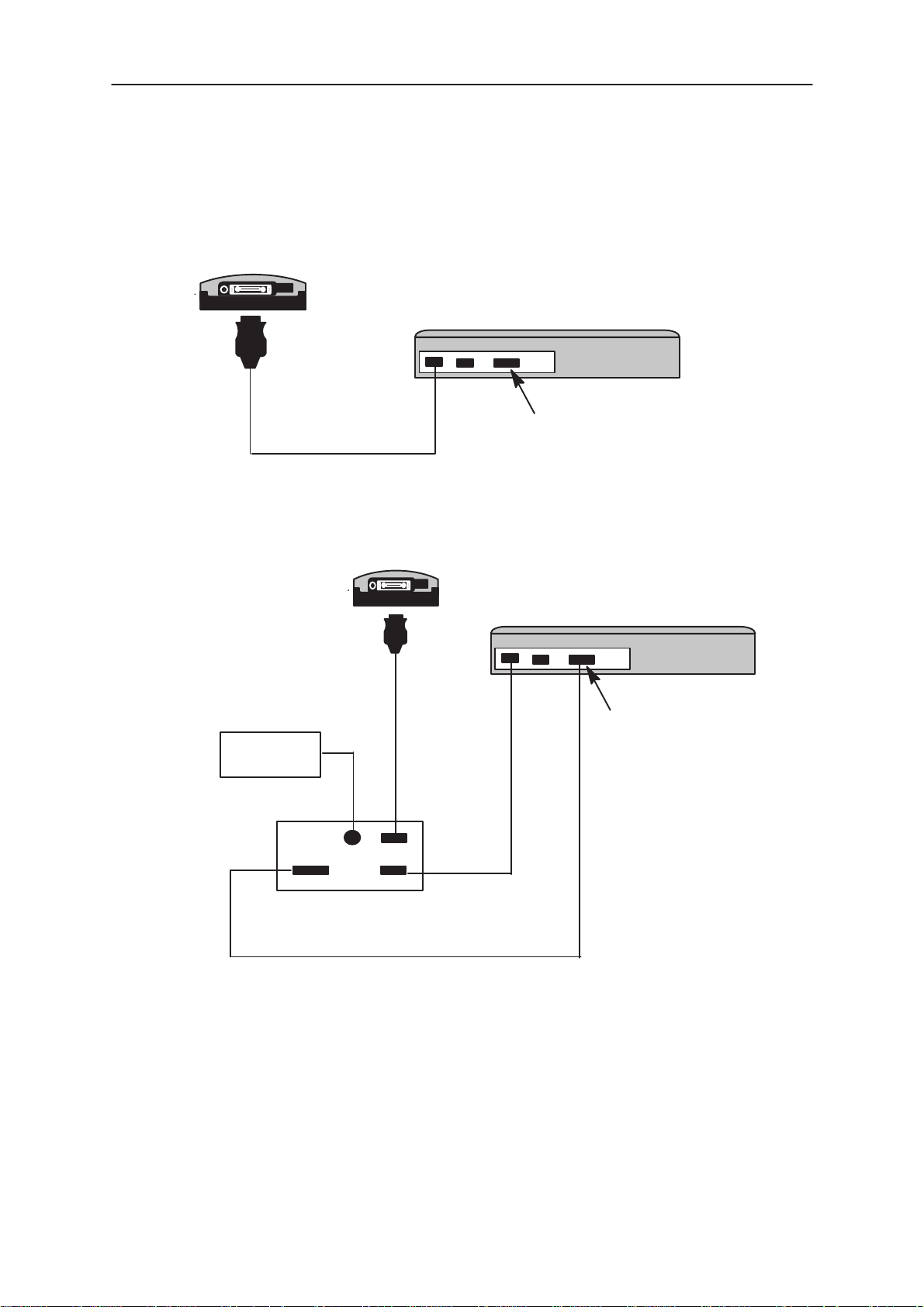
Figure 2. Servicing setup 7. . . . . . . . . . . . . . . . . . . . . . . . . . . . . . . . . . . . . . . .
Figure 3. Flash setup 7. . . . . . . . . . . . . . . . . . . . . . . . . . . . . . . . . . . . . . . . . . . .
Figure 4. WinTesla with loaded interfaces 8. . . . . . . . . . . . . . . . . . . . . . . . . .
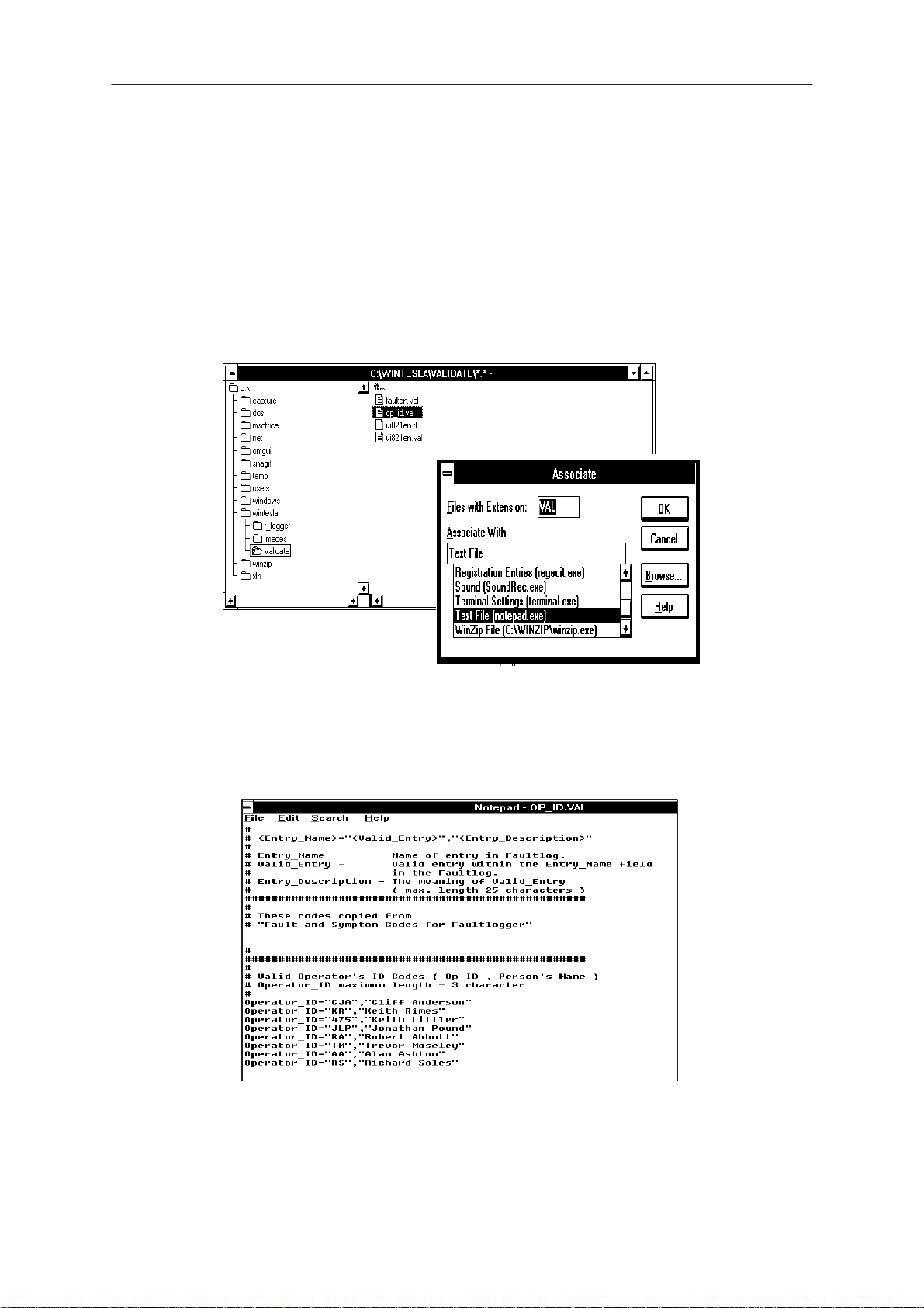
Figure 5. Accessing Op_ID. val file 9. . . . . . . . . . . . . . . . . . . . . . . . . . . . . . .
Figure 6. Editing Op_ID.val file 9. . . . . . . . . . . . . . . . . . . . . . . . . . . . . . . . . . .
Figure 7. Login Screen 10. . . . . . . . . . . . . . . . . . . . . . . . . . . . . . . . . . . . . . . . . .
Figure 8. FaultLog – configuration 16. . . . . . . . . . . . . . . . . . . . . . . . . . . . . . . . .
Figure 9. Editing fault, symptoms, modules files 19. . . . . . . . . . . . . . . . . . . . .
Figure 10. FaultLog – macro setup 21. . . . . . . . . . . . . . . . . . . . . . . . . . . . . . . .
Figure 11. Testing/Tuning with covers off 24. . . . . . . . . . . . . . . . . . . . . . . . . . .
Figure 12. Testing/Tuning with covers on 25. . . . . . . . . . . . . . . . . . . . . . . . . . .
Figure 13. CDMA TX Output power 41. . . . . . . . . . . . . . . . . . . . . . . . . . . . . . .
Figure 14. Auxiliary AGC Operation 1 45. . . . . . . . . . . . . . . . . . . . . . . . . . . . . .
Figure 15. Auxiliary AGC Operation 2 45. . . . . . . . . . . . . . . . . . . . . . . . . . . . . .
Figure 16. TX Slope 48. . . . . . . . . . . . . . . . . . . . . . . . . . . . . . . . . . . . . . . . . . . . .
Page 4
Original 11/97
Page 5

PAMS
WinTesla User Guide
Technical Documentation
Tesla for Windows Operating System
The name TESLA, when used by Nokia, is an acronym for TEst and
Service Locals Application. Tesla for WIndows (i.e. WinTesla) is a
software package designed to operate in the Microsoft Windows
environment. The software package is made of two modules, the
Wintesla core module and a service software module. The Wintesla
module is similar to an operating system for various service modules. In
this way many Nokia products can be serviced using one common
software package, running different service modules (in this case, for the
Nokia 2180).
Note: The Wintesla core module MUST be installed for ”any” service module to run.
Installing WinTesla On Your Hard Disk
The WinTesla core software is delivered on a 3.5” diskette and is
protected with a protection “key” (PKD–1), which must be attached to the
parallel port LPT 1 when the WinTesla service software is being used.
NHD–4
To install the WinTesla core software package, proceed as follows:
Note: For instructions on installing the HD881 service module (see Installing the
HD881 Service Module)
Insert the WinTesla Application diskette into drive A: of your PC.
From DOS ( NOT running windows ) type
A: INSTALL <Enter>
From Windows File Manager double click the mouse on
a:\install.exe
Follow the instructions given and use the
Repeat this procedure for the required module installation using the
upgrade
Note: For interim WinTesla releases use the upgrade option.
Your Windows desktop will now have a “Service Software” group and a
“Service Software” icon within that group.
To start the program, double click on the “Service Software” icon .
option instead of
(Windows will boot up automatically)
Or
new
option when requested.
new
.
Using The Windows Interface
If not familiar with the windows type interface, consult the
Windows User Guide
Original 11/97
for further information.
Microsoft
Page 5
Page 6
WinTesla User Guide
PAMS
NHD–4
Common User Interface
Due to the modular design of WinTesla, various generations of Nokia
products can be serviced, while sharing a similar user interface. The
common user interface is explained in the first part of this document and
is followed by the specific module information.
The software can be used to control the phone by entering commands via
the keyboard of a PC/AT – running MS Windows 3.1 or 3.11.
Note: Windows 95 and Windows NT are not supported.
This document refers to WinTesla Version 4.60 or greater.
Equipment Required
Computer : IBM 486 PC/AT or compatible with at least
one, unused serial port, COM1 or COM2 one parallel port
(LPT1), 5 Meg. hard disk space required, 16 Meg of RAM
: Any supported by MS Windows version 3.1 or 3.11
Technical Documentation
Operating System : DOS 5.0 or later running MS Windows
3.1 or 3.11
WinTesla Application Software (product code 0774046)
Software Protection Key PKD–1 (product code – 0750018)
Mechanical Connections
The software controls the phone via a separate adapter (DAU–2)
connected to the serial port of the PC and to the phone’s bottom
connector using the Nokia proprietary communication method called
M2BUS.
Attach the protection key PKD–1 to parallel port one (25–pin female
D–connector) of the PC. When connecting the PKD–1 to the parallel port
be sure that you insert the PC end of the PKD–1 to the PC (male side).
Page 6
Figure 1.Dongle Insertion
Original 11/97
Page 7
PAMS
WinTesla User Guide
Technical Documentation
The PKD–1 should not affect devices working with it. If some errors do
occur try printing without the PKD–1 connected. If printing is now OK
please contact your supplier who will endeavor to replace your PKD–1.
DAU–2
NHD–4
COM1 COM2 LPT–1
PC
PKD–1
Figure 2. Servicing setup
Power
Supply
Power
FPS–3C
COM1 COM2 LPT–1
PC
DAU–2
PKD–1 (connect to dongle)
Phone
SerialParallel
Figure 3. Flash setup
Original 11/97
Page 7
Page 8
WinTesla User Guide
PAMS
NHD–4
Using Wintesla
Phone Independence
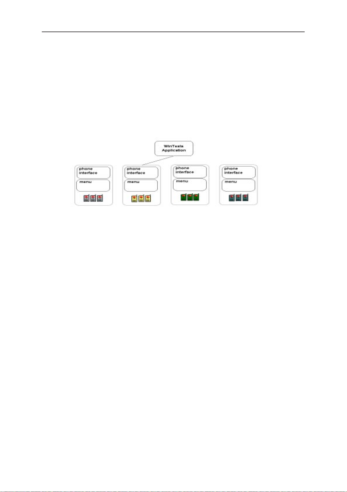
The WinTesla application, “WinTesla.exe”, is phone independent. It relies
on separate, phone specific, “modules” to provide communication, menus
and test algorithms.
Technical Documentation
Figure 4. WinTesla with loaded interfaces
For each phone type – or product family – a phone interface module and
menu module are required. The modularity of WinTesla allows support for
other languages, so one phone type may have one phone interface
module and several menu modules, all in different languages.
WinTesla allows you to select the language you wish to use (if available),
and will automatically load the correct phone interface module for the
connected phone. When a different phone type is connected, WinTesla
will load the new phone interface and associated menus.
Page 8
Original 11/97
Page 9
PAMS
WinTesla User Guide
Technical Documentation
Login ID Setup
Once the software has been installed you need to set up your own Login
ID (max. 3 characters). Start Windows file manager and locate the
validate\op_id.val
NO TAG.
Double clicking on the ‘
message, in order to avoid this use the File |Associate command in file
manager and link the file to the notebook application as shown below.
(located in the Wintesla subdir) file as shown in
Op_ID.val’
file (a text file) gives a windows error
NHD–4
Figure 5. Accessing Op_ID. val file
Now by double clicking on the ‘
Op_ID.val
’, notebook opens and your own
ID can be entered and saved accordingly. Enter or edit any operator
definitions following the existing format in this file.
Enter your id here
Figure 6. Editing Op_ID.val file
Original 11/97
Page 9
Page 10
WinTesla User Guide
PAMS
NHD–4
The Login Screen
When WinTesla first starts, the Login screen below will appear. Type in
your 3 character ID and press <Enter> or click on the OK button.
Technical Documentation
Figure 7. Login Screen
If WinTesla can not find the file,
then the OK button will be ‘greyed’.
If CANCEL is clicked then the Fault Logging feature of WinTesla will be
deactivated.
op_id.val
, which contains the Login IDs,
Page 10
Original 11/97
Page 11
PAMS
WinTesla User Guide
Technical Documentation
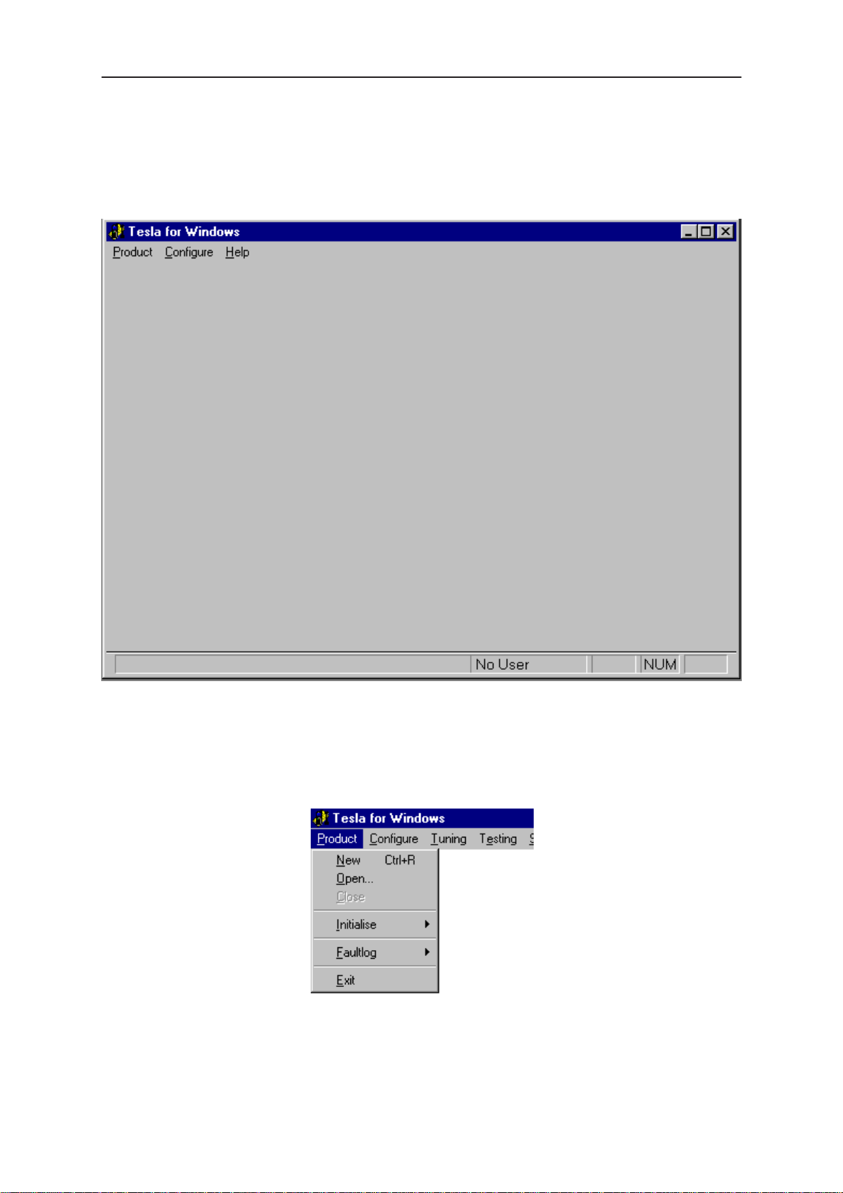
The WinTesla Screen
The main WinTesla screen – if no phone is attached – is displayed with 3
menu items at the top of the screen and a status bar at the bottom.
NHD–4
The information on the left of the status bar will be used to provide
information when WinTesla is performing tasks: such as reading data from
the phone. The status bar also includes the name of the current user.
The Product Menu
Original 11/97
Page 11
Page 12
WinTesla User Guide
PAMS
NHD–4
New (Ctrl+R)
The ‘New’ function (which can also be activated by pressing Ctrl+R ) is
used to scan for a phone when either the automatic rescan option is off or
the automatic rescan timer has not expired ( see
for automatic rescan ).
If the phone type is unrecognized or unsupported by the current WinTesla
system then a warning message will be displayed.
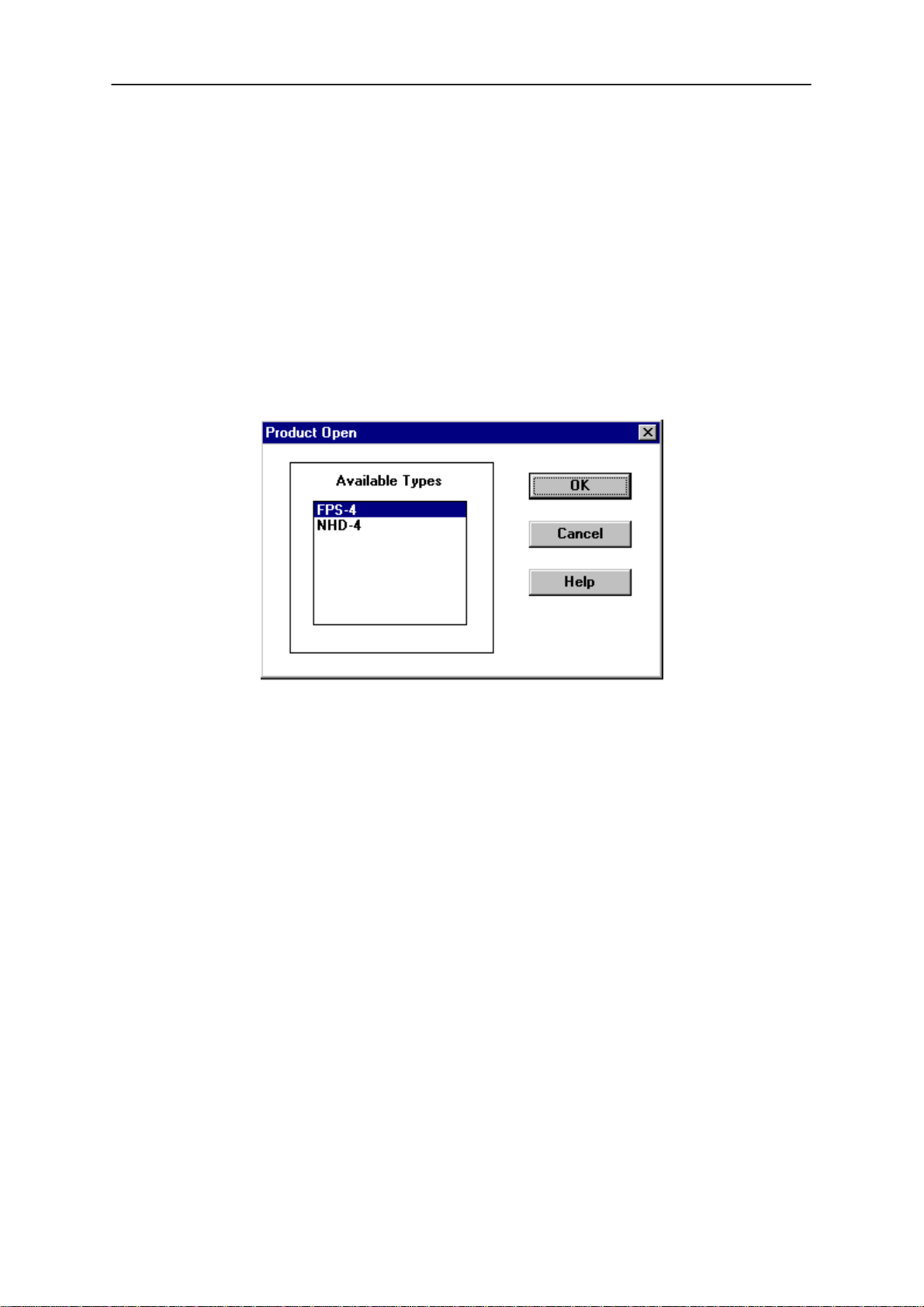
Open
The ‘Open’ function allows you to ‘force load’ a phone interface, even if
there is no phone connected to the system.
Technical Documentation
Configure|Options section
Close
A dialog box will appear and list the supported phone types (see figure
above). To select a particular phone type to load; highlight the phone type
name and click on OK.
Clicking on CANCEL will stop the request and no new phone type will be
loaded.
Loading a phone interface will disable the automatic rescan function ( see
Configure|Options section for automatic rescan).
This function will close the currently loaded phone type interface that had
been loaded using the
Product|Open function. You can not ‘Close’ a loaded
phone type interface if it was loaded by a rescan.
Page 12
Original 11/97
Page 13
PAMS
WinTesla User Guide
Technical Documentation
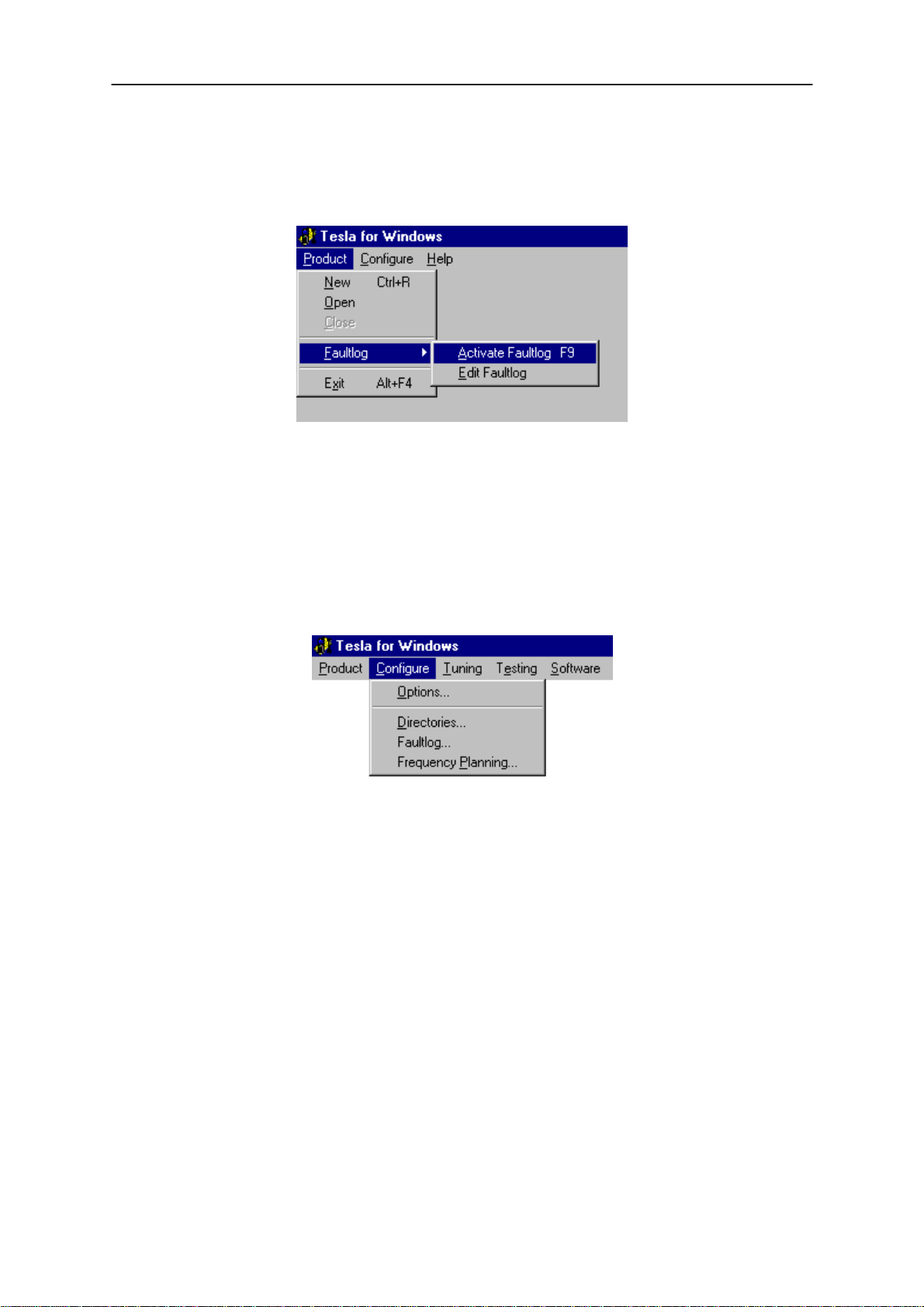
FaultLog
The ‘FaultLog’ option has a sub–menu (below). These functions are
described in the ‘FaultLog Application’ section.
If the FaultLog function has been disabled – either because the Login ID
was not correct or disabled through the
these menus will be ‘greyed’ and made un–selectable.
Exit (Alt+F4)
NHD–4
Configure|FaultLog function – then
Selecting this option will shut–down the WinTesla program.
The Configure Menu
The configuration menu allows you to setup such things as directory
paths, user interface language and FaultLog options.
Original 11/97
Page 13
Page 14
WinTesla User Guide
PAMS
NHD–4
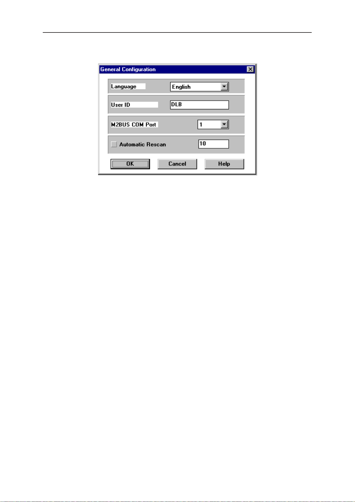
Options
Language
Technical Documentation
This option allows you to change the language used in the WinTesla
application.
Current Password / New Password / Retype Password
Currently not available
User ID
Allows the user ID to be entered if the users name is setup in the
opt_id.val (validation) file.
M2BUS COM Port
This option allows you to select which communications port the phone is
to be connected. The change will take place immediately after pressing
OK.
Automatic Rescan
Automatic rescan is a mechanism to automatically check for a new phone;
the time between re–scans is user configurable. When a phone is
scanned and recognized, the corresponding phone interface and menu
are loaded, extending the main menu at the top of the screen and
displaying the phone type and description at the bottom of the screen.
Product|New (or Ctrl+R ) function can be used to rescan the phone
The
in–between automatic rescans or when automatic rescan has been
disabled. The automatic re–scan mechanism is disabled when the
Product|Open function is used to load a phone interface.
Page 14
A tick in the check–box indicates that the automatic rescan option has
been enabled. Clicking on the check–box (making the check–box blank)
will disable the automatic re–scan option. The time between re–scans (in
seconds) is entered into the edit box.
Pressing the OK button will save any changes made. Pressing CANCEL
will discard any changes you may have made.
Original 11/97
Page 15
PAMS
WinTesla User Guide
Technical Documentation
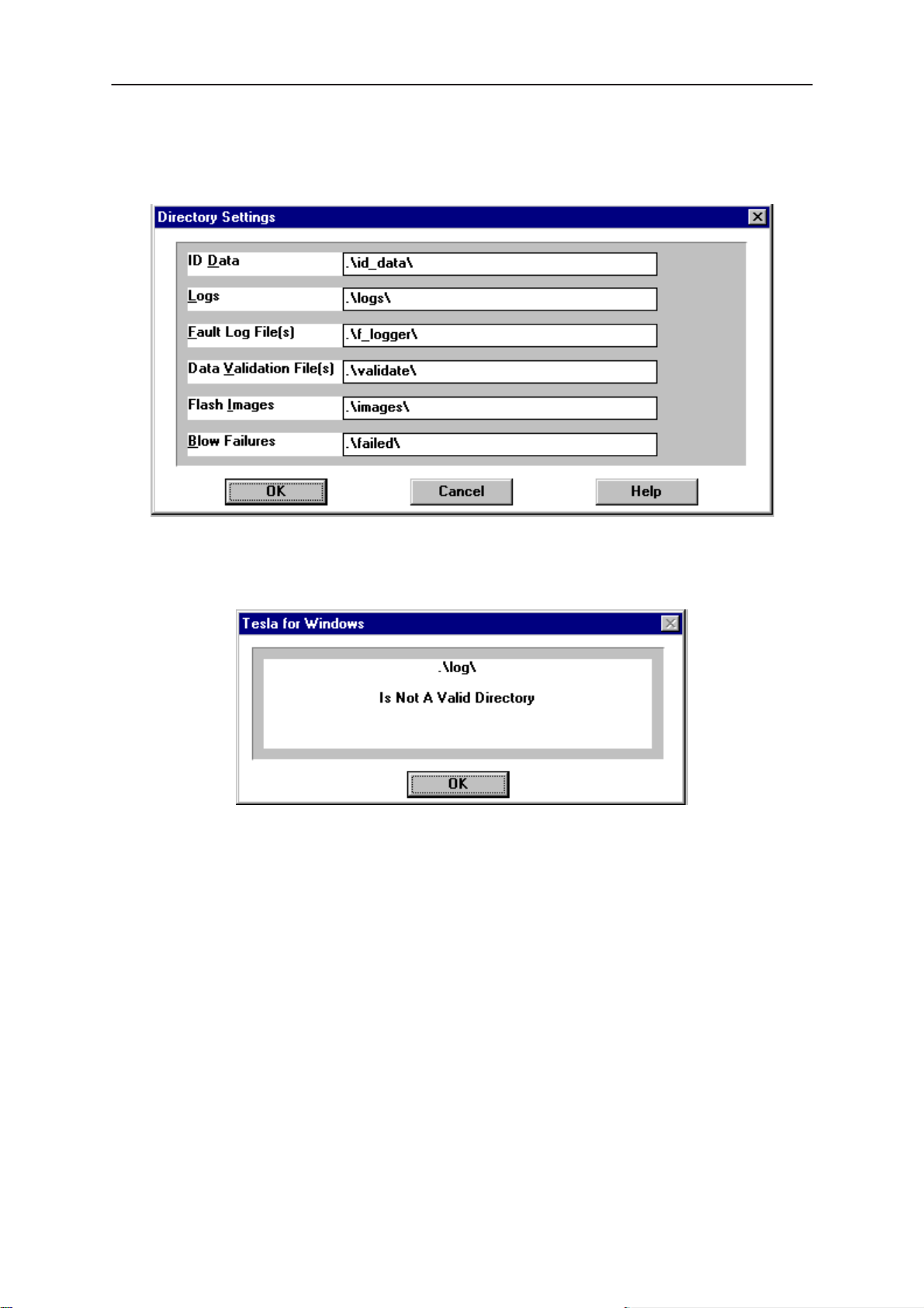
Directories
This function allows you to organize your data into different directories.
The directories must already exist. If an invalid directory is entered then
an error message will be displayed (below).
NHD–4
The use of a backslash (‘\’) at the end of the directory name is optional.
Clicking on the OK button will save your changes.
Original 11/97
Page 15
Page 16
WinTesla User Guide
PAMS
NHD–4
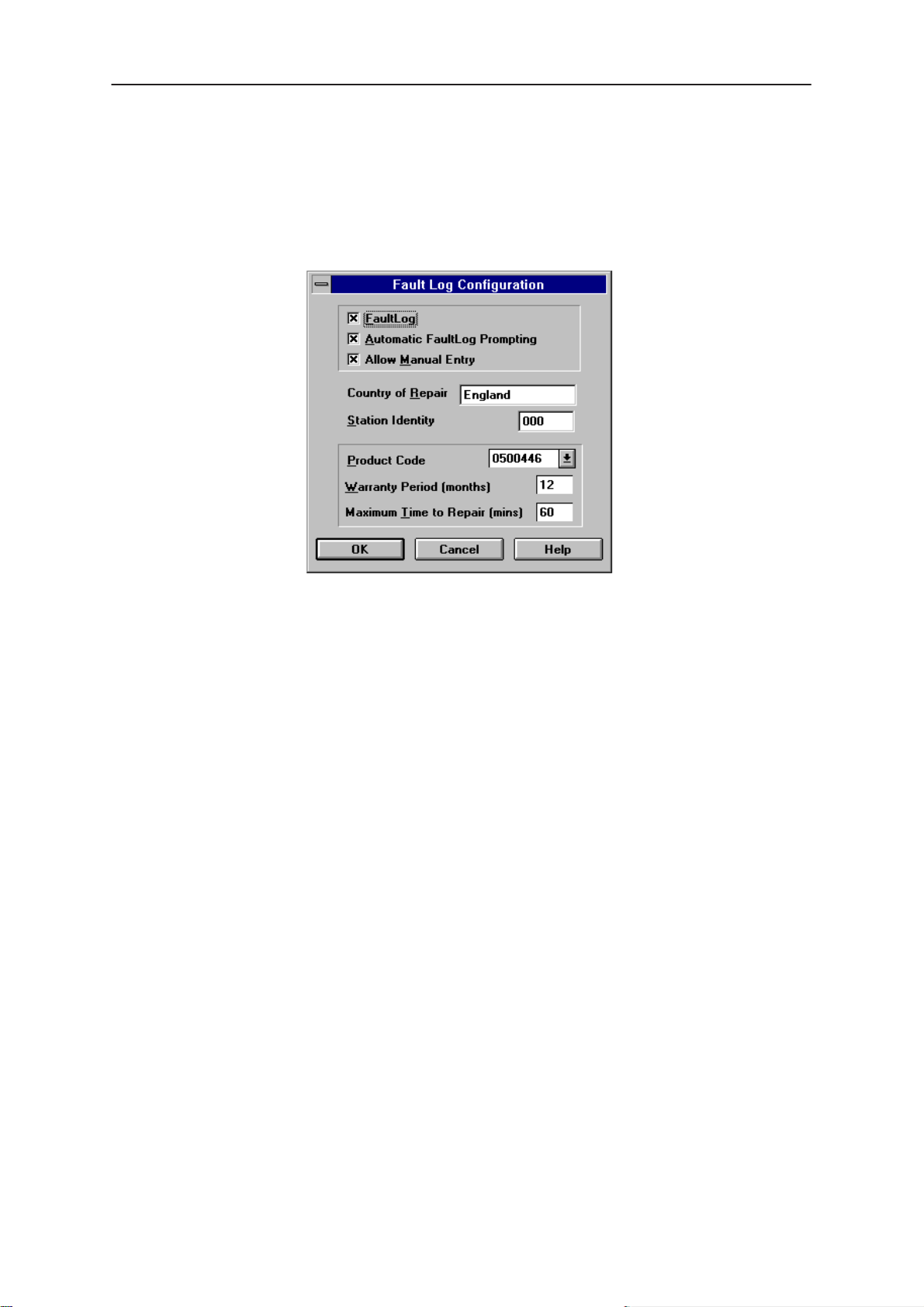
Fault Log Configuration
Fault Log is a feature that allows the PC to create a record of each phone
that is serviced for historical tracking. This function allows you to configure
the FaultLog mechanism. Clicking OK after making selections, saves all
changes made.
Technical Documentation
Figure 8. FaultLog – configuration
Fault Log
This option allows you to enable or disable the FaultLog mechanism.
Choosing to disable the FaultLog mechanism results in the
|FaultLog options being ‘greyed’ and the F9 button being disabled.
Allow Manual Entry
This option allows you to disable manual entry of data that was
unavailable from the phone.
Automatic Fault Log Prompting
Enabling this option results in a prompt being displayed if the phone has
changed.
Station Identity
Enter the unique identity of your ‘workstation’; this ID is used to write
FaultLog files.
Country Of Repair
Enter the country of repair.
Product
Warranty Period ( months )
Each product code has an associated warranty period. This option allows
you to change those warranty periods. If no phone is connected then all
product codes supported will be displayed. However, if a phone is
connected then only the product codes associated with that phone type
are displayed.
Page 16
Original 11/97
Page 17

PAMS
WinTesla User Guide
Technical Documentation
Note: Changing the Warranty Period in the Fault Log data file has no affect on the
products warranty terms as stated from the manufacturer.
Maximum Time To Repair ( minutes )
Enter the maximum time allowed to repair a phone.
1. Fault Log Application.
The aim of the Fault Log application is to provide NMP After Sales
Companies worldwide a standard method for the collection of Fault and
Repair Data from their service process’s. This information can also be
used by NMP R&D and Manufacturing organizations as well.
The Fault Log application can be regarded as a data entry sub–routine
run from the WinTesla Service Software package at the end of a repair.
This allows for quick and uniform recording of the service performed on
the product.
Each product repaired, will generate one unique record in a FaultLog file
consisting of up to 37 data fields containing information about the product
and how it was repaired. This information is read automatically where
possible, from the products own internal EEPROM and then entered
manually by the Service Technician to form a complete service record.
NHD–4
For more advanced implementations, the repair records are copied and
collected by the electronic mail system installed in the Service Center and
are sent electronically to a Central Service Database located in Finland.
Completing a FaultLog Record
Once WinTesla has been configured correctly it operates in the following
manner:–
Wintesla automatically reads the product details from the
products EEPROM and writes them as a record to a
pre–determined file.
Proceed with the repair task, utilising a combination of
software driven tuning and hardware modifications.
On completion of the repair task you have a choice:
A.)With the product still connected to the PC, manually display
the repair data entry screen by selecting Function Button F9.
B.) Alternatively, the product can be disconnected and the next
product for repair connected in its place.
So long as Automatic Prompting is enabled then the previous products
repair data entry screen will be displayed.
– Enter the repair work performed on the product in the repair
data screen.
Original 11/97
– Check the automatic data for this product, read earlier, to
ensure its accuracy.
– When satisfied with the data, save the entry. This process
adds a complete record containing the product details and
the repair details to the FaultLog output file.
Page 17
Page 18

WinTesla User Guide
PAMS
NHD–4
Technical Documentation
The output file can then be manipulated by a number of different systems,
as required, as a detailed record of the product fault.
To attempt to record all of this information 37 data fields are defined for
each FaultLog record. These can be split as follows:–
– Product definition information fields
– Repair / fault information fields.
Most products have their information stored in EEPROM, WinTesla
automatically reads this information from the EEPROM and writes it to the
FaultLog record. This part of the record is shown below.
Operator
Phone
Fault
Fields that are ‘greyed out’ etc. are data that has been automatically
retrieved from the phone’s EEPROM. All other fields are entered
manually; fields are summarized below.
Automatic: Station, Country
Manual :
Automatic: Product code, Production SN, Order No., Hardware
ID, Software version, Mfr. SN/ESN/IMEI, Mfr. Date,
Manual:
Automatic: none
Manual
The current FaultLog application allows for the entering of three priority
levels of fault / repair information seen as
faults.
Time to repair, Job ID, Operator ID
Issue date
Warranty
Module, Fault, Symptom, Circuit ref., Part Number
Primary, Secondary
and
Tertiary
Page 18
Original 11/97
Page 19
PAMS
WinTesla User Guide
Technical Documentation
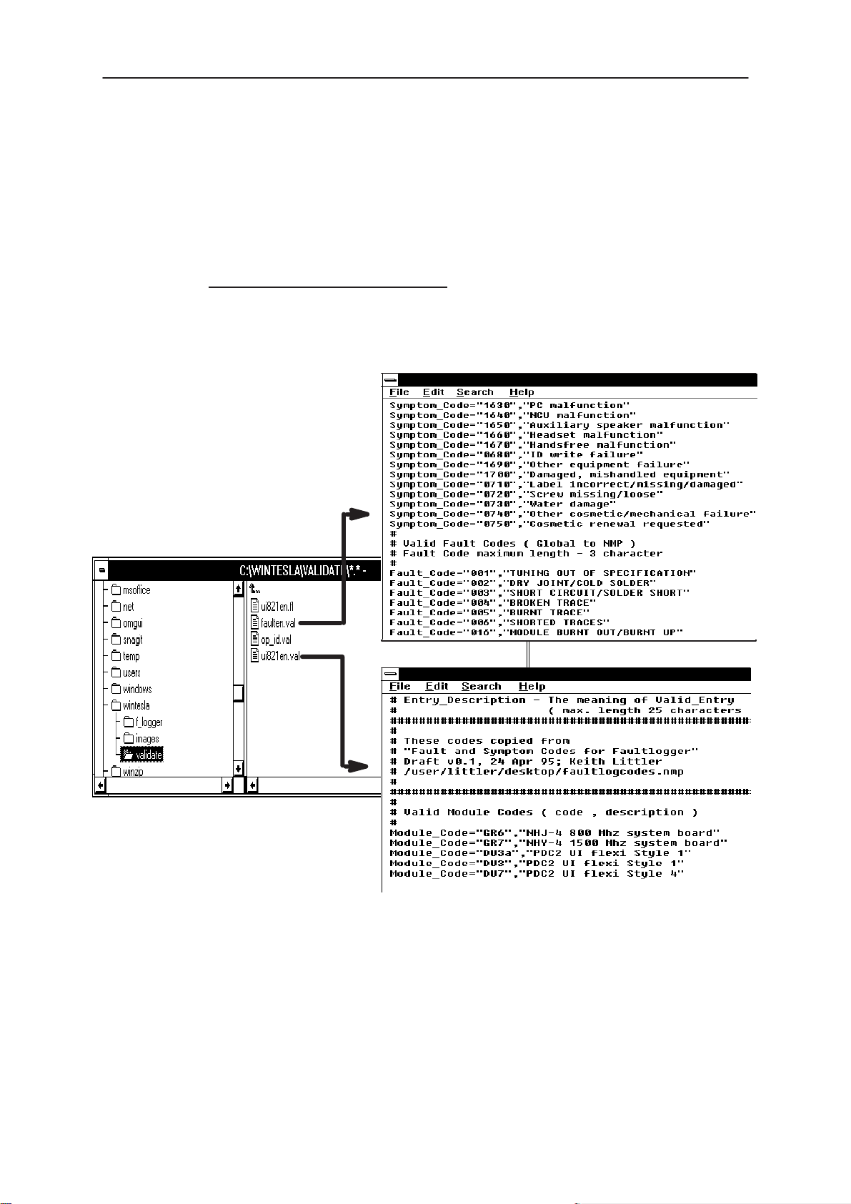
Module, Fault
The
arrows alongside each respective field.
A comprehensive list of faults and symptoms as well as all current
modules are already listed within the software. These three fields can be
updated by accessing and editing the following files ias described in each
file.
Field DOS File
–
–
and
Symptom
Modules
nhd4en.val–
Faults, Symptoms
NHD–4
fields have variables selected by the
faulten.val
Notepad – FAULTEN.VAL
Other Parts Replaced
Automatic none
Manual all fields
Enter other parts that have been replaced i.e. for wear and tear purposes
etc..
Notepad – UI821EN.VAL
Figure 9. Editing fault, symptoms, modules files
Original 11/97
Page 19
Page 20

WinTesla User Guide
PAMS
NHD–4
This Entry
Automatic ; Entry Indicator, Date, Time
Manual ;
Cost
Automatic ; Total
Manual ;
This facility is for the use of third party repairers only
FaultLog Macros
The Macro sub–menu can be accessed by selecting the
the FaultLog main screen.
Macro’s in FaultLog are a set of standard repair actions defined and
stored in order to represent frequently repeated repairs. These Macro’s
are related to the Product Code of the product, so whatever product is
connected, FaultLog will display the Macro list for that particular Product
Code.
Technical Documentation
Comment
Parts, Labour
macros button on
A Macro’s standard repair information can also be pasted into the
FaultLog record for that product.
Macro’s are saved initially under a name you can define yourself from the
main FaultLog screen. All the information contained in the manually
entered fields i.e. Module, Fault, Symptom, Circuit Ref and Part Number is
recorded and saved under this name.
Page 20
Original 11/97
Page 21
PAMS
WinTesla User Guide
Technical Documentation
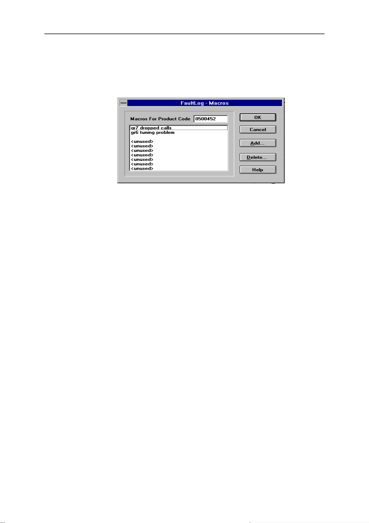
Setting up a macro
1. After completing a manual entry as normal but before saving the
record, select the
definition screen.
2. Place the cursor over the next available Macro entry then select
Add
NHD–4
Macros button. This will bring you into the Macro
Figure 10. FaultLog – macro setup
Help
3. Give the Macro record a meaningful name and press OK. You
have now saved the repair data into a Macro for future use.
4. Use the
Delete function to remove unwanted macros
Now, when a similar problem is seen with another unit you can recall this
saved repair information into the units FaultLog record. If needed, the
FaultLog record can be edited after being recalled to customize the repair
before saving the FaultLog record.
There are a maximum of 10 Macro’s definable for each Product Code. If
an eleventh is required, it will be necessary to overwrite one of the
previous Macro’s.
The Macro definition file is called
macro.fl
and will be found in the path
specified for the data validation files. If this path is a networked path all
operators connected to the network will be permitted to share a common
Macro list helping with reporting uniformity.
An extensive help facility is available by clicking any screen or toolbar help
button and features convenient hypertext linking for easy navigation.
Original 11/97
Page 21
Page 22

WinTesla User Guide
PAMS
NHD–4
HD881 Module
Information in this section is specific to the HD881 module and assumes
that the setup procedures in the common interface section have been
carried out.
Installing the HD881 Service Module
The HD881 Service module software is delivered on a 3.5” diskette and
must be run under the Wintesla core software package.
To install the HD881 Service Module software, proceed as follows:
Insert the HD881 Service Module diskette into drive A: of your PC.
From Windows File Manager select the file a:\install.exe and
press OK.
Follow the on screen instructions and select the
prompted to do so.
Caution: The service module requires the Wintesla core software
application to be installed first for this module to function.
Technical Documentation
new
install option when
Note: Be sure to install the Service Module in the same directory as the Wintesla
core software application.
Required Servicing Equipment
The following is a list of equipment that is needed in order to service the
HD881 family of products along with their respective product codes.
HD881 Software Service Module (0774062)
Dongle ‘blackbox’ adapter DBA–1 (0630044)
M2BUS adapter DAU–2 (0750006)
RS–232 adapter, 9–to–25 pins (4626170)
RS–232 cable (0730090)
Centronics cable (0730029)
Service cable SCS –1 (0770010)
Service cable SCS–10 (0775059)
Audio cable ADS–1 (0730011)
Modular cable XCM–1 (4626131)
Flash Programmer Set FPS–3C (0271330)
Page 22
Power connector PCS–1 (0730012)
Modular T Connector cable (4626134)
Dummy Battery BTS–4 (0770009)
Covers off Jig JBS–8 (0770014)
Service box JBS–7 (0770015)
Original 11/97
Page 23

PAMS
WinTesla User Guide
Technical Documentation
Equipment Setup
Caution: Make sure that you have switched off the PC and the printer
before making connections !
Caution: Do not connect the PKD–1 key to the serial port. You may
damage your PKD–1 !
Attach the protection key PKD–1 to parallel port one (25–pin female
D–connector) of the PC. When connecting the PKD–1 to the parallel port
be sure that you insert the PC end of the PKD–1 to the PC (male side). If
you use a printer on parallel port one, place the PKD–1 between the PC
and your printer cable.
Next connect the M2BUS adapter to the serial port (RS–232) of the
computer. In case you are using a 9–pin serial port (normal with an AT
set) use the mating adapter supplied with the M2BUS adapter.
Attach one end of the XCM–1 modular cable to the DAU–2 PC/M2BUS
adapter and the other end to the JBS–7 service box. Use suitable adapter,
SCS–1 service cable when the covers of the phone are in place, JBS–8
test frame with the phone covers off, and attach it to the phone. Then
connect it to the service box.
NHD–4
Original 11/97
Page 23
Page 24
WinTesla User Guide
PAMS
NHD–4
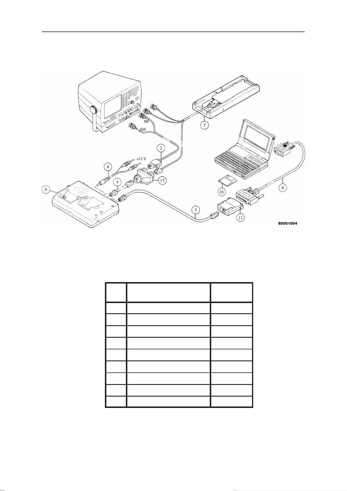
Dealer Setups
Technical Documentation
Figure 11. Testing/Tuning with covers off
Item Description Product
Code
2 ADS–1 0730011
3 XCM–1 4626170
4 PCS–1 0730012
7 JBS–8 0770014
8 RS232 Adapter 4626170
9 JBS–7 0770015
11 DAU–2 0750006
16 Software diskette 0774062
17 Modular T connector 4626134
Page 24
Original 11/97
Page 25

PAMS
WinTesla User Guide
Technical Documentation
NHD–4
Figure 12. Testing/Tuning with covers on
Item Description Product
Code
2 ADS–1 0730011
3 XCM–1 4626170
4 PCS–1 0730012
5 SCS–1 0770010
6 BTS–4 0770009
8 RS232 Adapter 4626170
9 JBS–7 0770015
11 DAU–2 0750006
16 SWSA881 0774062
17 Modular T connector 4626134
Original 11/97
Page 25
Page 26

WinTesla User Guide
PAMS
NHD–4
Main Menu
The main menu bar below appears when HD881 initializes, adding the
following new categories,
Product
Product
The following items are added to this menu when HD881 is recognized:
Initialize
Allows the phone to be set up in either
Normal Mode
and
Configure
Technical Documentation
Tuning,Testing, Software, Dealer
have also changed.
Normal, Local or Minimum
and
Help.
mode.
When selecting
base station and a message displays this. This is ”normal” operation
mode of the phone.
Local Mode
When
operation and set to a special mode allowing Tuning and Testing to be
done.
Minimum Mode
When
MCU will communicate with the PC using the Service Software. This
mode is used for Flash software changes.
Local
Minimum
Configure
Channel Settings
This configures the channel number, for a product type, to be
High
in order to allow losses to be configured for manual testing.
Norma
mode is selected the phone is suspended from normal
mode is selected the phone is deactivated and only the
l mode, the phone tries to synchronize into the
Low, Mid,
Page 26
Original 11/97
Page 27

PAMS
WinTesla User Guide
Technical Documentation
Tuning Steps of Radio Unit
The Service software program places the phone into the Locals mode, in
which the phone can be outwardly controlled via the M2BUS interface.
The tuning values of the phone reside on the EEPROM. Before tuning,
these values are read by the Service software and the user can change
these values with tuning functions.
Note: During tuning, keep the following in mind:
– Take care not to damage sensitive measuring instruments with exces-
sive RF power.
– Carry out all tuning steps in the shortest possible time to avoid exces-
sive heating of RF units.
– Perform all tuning steps in the order presented.
– Never try to mask a fault by tuning it out!
NHD–4
Accuracy of the Equipment During Measurement
– Power supply 1; nominal voltage 12 ±0.5 V current cap. min. 1.5 A for
service box (JBS–7).
– Power supply 2 ;nominal voltage 6.0 ±0.1 V, current cap. min. 1.5 A.
– Modulation analyzer power level resolution 0.1 dB, accuracy ±0.5 dB.
Frequency counter accuracy 0.1 ppm 〈±80 Hz).
– RF generator; frequency res. 10 Hz amplitude res. 0.1 dB frequency
stab. ±0.25 ppm.
– Spectrum analyzer; dynamic range 70 dB, accuracy ±1 dB (For power
level measurement accuracy ±0.5 dB).
Original 11/97
Page 27
Page 28

WinTesla User Guide
PAMS
NHD–4
General
Caution: The phone can not be Tuned properly if connected to the
FPS–3C Flash Programming Box. Please use only one of the setup
configurations listed in the “Dealer Setups” section of the NHD–4NX
Service Manual.
Battery Voltage Adjustment
A reference value for the battery is calibrated by using an accurate 6.0 V
supply.
Calibration of the A/D converter channels:
– Using the JBS–7 service jig, replace the standard battery of the phone
with the dummy battery BTS–4.
– Apply +6.0 V to dummy battery.
– Select ” Tuning – Battery voltage”.
– The Program reads the 6 Volts applied and displays the corresponding
A/D reading fed to the phone via the VBATT line.
Technical Documentation
– Store this new value to the phone by pressing ”Tune”. Then Exit
Charge Voltage Adjustment
A reference value for charge voltage is set by using an accurate 6.0 V
supply.
Calibration of the charge voltage:
– Using the JBS–7 service jig, replace the standard battery of the phone
with the dummy battery BTS–4.
– Apply +6 V to VCHARGE line.
– Select ”Tuning – Charge voltage ”.
– The Program reads 6 V, A/D reading fed to phone VCHARGE line.
– Store this new value to the phone by pressing ”Tune”. Then Exit
RF Temperature Adjustment
This adjustment should be made with the phone at room temperature. It
is important that all RF transmitter tunings be done as quickly as possible.
This is to ensure that this reference temperature adjustment is within limits
required for temperature compensation.
Page 28
Calibration of the RF Temperature:
– Using the JBS–7 service jig, replace the standard battery of the phone
with the dummy battery BTS–4.
– Apply +6 V to VCHARGE line.
– Select ”Tuning – RF Temperature ”.
– Press ”Tune”. The Program reads the internal thermistor value and
stores this value to the phone.
Original 11/97
Page 29

PAMS
WinTesla User Guide
Technical Documentation
AMPS Tuning
Analog Bias Current Tuning
The purpose of this tuning is to optimize transmitter‘s efficiency.
Bias tuning is needed if:
– PLL circuit (N500) is replaced
– Any of the power amplifiers V110, V111, V112, V113 or the duplex filter
is replaced
– Any of power amplifier resistors are replaced
This affects only power consumption and thus gain and linearity of power
amplifier.
Description of Tuning
This tuning sets the bias current to the CLY–10 (V113) final PA gain stage
for AMPS mode operation at output power level 7. The TXB PDM is used
to set this bias. The bias is set to provide 100 mA of current to the
CLY–10 in this state. This 100 mA current is the amount of current draw
above the quiescent state of the phone in AMPS mode, as described in
the AMPS Mode Quiescent Current section 3.1. Note that the CLY–10 will
draw additional current at higher output AMPS power levels. This is due
to self biasing by the drive signal.
NHD–4
Analog bias current tuning steps & equipment:
– Using the JBS–7 service jig, replace the standard battery of the phone
with the dummy battery BTS–4.
– Apply +6.0 V to dummy battery.
– Start the service software and go to ”Main” menu.
– Select ” Tuning – Analog Bias Tuning ”
– Measure step1 current consumption from power supply current display
and input it to Service software prompt. Then press OK.
– Adjust first analog mode bias current to the target value displayed in
tuning dialog by using Arrow keys or PgUp/PgDn keys.
Original 11/97
Page 29
Page 30

WinTesla User Guide
PAMS
NHD–4
AFC Tuning
This tuning is done to calibrate the VCTCXO oscillator frequency.
This tuning is needed if the VCTCXO (G300), any component of AFC–line
or the CDRFI (N700) is changed.
Description of Tuning
This procedure tunes the VCTCXO to 15.36 MHz. The unmodulated
AMPS transmitter carrier on channel 384 is used to perform this test. The
output carrier is monitored with a spectrum analyzer with a 10 kHz span.
The VCTCXO is tuned by adjusting the AFC PDM until the carrier is on
frequency at 836.52 MHz within 200 Hz. For standard AFC operation the
RX_SLOPE PDM is high, at approximately 3.15 V.
AFC calibration steps & equipment:
– Using the JBS–7 service jig, replace the standard battery of the phone
with the dummy battery BTS–4.
Technical Documentation
– Apply +6.0 V to dummy battery.
– Select ” Tuning – AFC ”
– Connect the modulation (or spectrum) analyzer to antenna connector
and measure transmitter frequency. Adjust frequency to 836.52 MHz +
– 200Hz with arrow or PgUp/PgDn –keys.
– Press <save & exit> to store value to EEPROM or <cancel> to exit
without saving.
Page 30
Original 11/97
Page 31

PAMS
WinTesla User Guide
Technical Documentation
Deaf Channel Frequency Tuning
This tuning is done to calibrate the VCTCXO oscillator frequency to adjust
for “deaf” or “blocked” AMPS channels.
This tuning is needed if the VCTCXO (G300), any component of AFC–line
or the CDRFI (N700) is changed.
Description of Tuning
This is a secondary tuning done on the VCTCXO for a special case
involving AMPS channels 184, 440 and 696, known as the Deaf channels.
This tuning is performed exactly as it was in the AFC Tuning above, but
now channel 440 is used rather than channel 384. In this case the
RX_SLOPE PDM is low at approximately 0.0 V. Again the AFC PDM is
adjusted to tune the transmit carrier to within 200 Hz of the center
frequency, this time 838.20 MHz. Consult the HD881 Synthesizer
Functional Description for more information on the Deaf Channel
functionality of the synthesizer.
NHD–4
AFC calibration steps & equipment:
– Using the JBS–7 service jig, replace the standard battery of the phone
with the dummy battery BTS–4.
– Apply +6.0 V to dummy battery.
– Select ” Tuning – Deaf Channel Frequency”
– Connect the modulation (or spectrum) analyzer to antenna connector
and measure transmitter frequency. Adjust frequency to 838.20 MHz +
– 200Hz with arrow or PgUp/PgDn –keys.
– Press <save & exit> to store value to EEPROM or <Close> to exit
without saving.
Original 11/97
Page 31
Page 32

WinTesla User Guide
PAMS
NHD–4
TX Output Power
This adjustment loads the power levels of the phone transmitter into
EEPROM. When doing this, a power meter must be used.
This tuning is needed if CDRFI (N700), duplex filter, power RF transistors
or power control parts are replaced
Description of Tuning
This tuning sets the AMPS transmitter power levels 2–7 to the required
power output. To perform this tuning the phone is placed in AMPS Mode
and the carrier is turned on. AMPS TX power control on the 2180 is done
by adjusting the TXI_REF PDM.
Power levels programming:
– Using the JBS–7 service jig, replace the standard battery of the phone
with the dummy battery BTS–4.
– Apply +6.0 V to dummy battery.
Technical Documentation
– Select ” Tuning – TX power level”
– Connect power meter to antenna via the phone’s bottom connector.
– Adjust the tuning value with the arrow keys (fine tuning) or with PgUp
and PgDn–keys (coarse tuning) until the desired output power is
reached. Tuning starts from the highest power level.
Note: There is a little cable loss between the antenna connector and the RF power
meter. The total attenuation of 1 meter long RG–58 cable and the service box is about
0.7 dB. Please take this into account.
Power
level
Target Power level
values (milliWatts)
Example value
A/D converter
2 26.8 dB (479 mW) 143
3 22.8 dB (239.9 mW) 0
4 18.8 dB (95.5 mW) –40
5 14.8 dB (38.0 mW) –89
6 10.8 dB (15.1 mW) –129
7 6.8 dB (6.03 mW) –161
– Use the <TAB> key to move to tune the next power level.
Page 32
– Press <Save & exit> to store calculated values to the phone and exit
or <Close> to exit without storing.
Original 11/97
Page 33

PAMS
WinTesla User Guide
Technical Documentation
TX Modulation Index Calibration
This tuning is done to adjust the FM Modulators and the gain of TX–audio
path.
This tuning is needed if Codec (N600), or components D1, N500 or D704
is changed.
Description of Tuning
This tuning adjusts the level of FM modulation on the AMPS transmitter.
To do this, the Signaling Tone (ST) is turned on and the modulation level
on the transmit signal is monitored. The TX_MOD level in the DSP is
adjusted in software. This value controls the level of the audio frequency
tone leaving the CDRFI pin 25 on route to the VHF synthesizer for
modulation. At the CDRFI, pin 25 this line is called DAFOUT. Into the
VHF synthesizer it named ANATX. For the ST tone the TX_MOD level is
adjusted until the FM modulation is 8 kHz +/– 0.2 kHz
FM Modulation adjustment:
NHD–4
– Using the JBS–7 service jig, replace the standard battery of the phone
with the dummy battery BTS–4.
– Apply +6.0 V to dummy battery.
– Select ” Tuning – TX Modulation Index”
– Connect modulation analyzer to antenna connector. Use 20 kHz low
pass filter.
– Use PgUp/PgDn keys to adjust to 8.0 kHz +/– 100 Hz. (ST signal is
switched ON)
– Press <Save & Exit> to store values to the phone and exit or <Cancel>
to exit without saving.
Original 11/97
Page 33
Page 34

WinTesla User Guide
PAMS
NHD–4
RSSI
This step consist of tuning the analog mode reference value for the
receiver signal strength meter.
This tuning is needed if FM detector (D1); any parts of RX–chain; duplex
filter or saw filter has been changed
Note: Take into account any cable loss.
Description of Tuning
This tuning records the RSSI values for low and high power received
signals. This is done by feeding a –95 dBm signal into the AMPS receiver
at channel 384 with modulation of 8 kHz FM, 1 kHz audio. The RSSI
voltage generated by the AMPS receiver IC (D1) routes to the MCU, pin
58. The MCU reads the RSSI value resulting from its onboard A/D
converter. For the –65 dBm input signal this digital value is stored in
EEPROM as RSSI_HI. This process is repeated for a –65 dBm
modulated input signal, and the stored value is termed RSSI_LO. The
RSSI values read by the MCU are 10 bit numbers.
Technical Documentation
Analog RSSI level tuning steps:
– Using the JBS–7 service jig, replace the standard battery of the phone
with the dummy battery BTS–4.
– Apply +6.0 V to dummy battery.
– Connect signal generator to antenna connector at 881.52 MHz (chan-
nel 384) using modulating frequency 1.0 kHz with a deviation of 8.0
kHz and level of –95 dBm.
– Select ” Tuning – RSSI”.
– The program reads the reference value stored on phone together with
the reference value read from A/D converter.
– A/D converter value should be between 0 – 255.
– Press <Tune> to store values to the phone and exit or <Cancel> to exit
without storing.
– Connect signal generator to antenna connector at 881.52 MHz (chan-
nel 384) using modulating frequency 1.0 kHz with a deviation of 8.0
kHz and level of –65 dBm.
– A/D converter value should be between 0 – 255.
Page 34
– Press <Tune> to store values to the phone and exit or <Cancel> to exit
without storing.
Original 11/97
Page 35

PAMS
WinTesla User Guide
Technical Documentation
RX Audio Gain
The purpose of this tuning operation is to calibrate the gain of audio path.
This tuning is needed if FM detector (D1) including surrounding
components of FM detector or Audio Codec (N600) is changed
Description of Tuning
This tuning adjusts ratio of output audio gain vs. the level of received FM
frequency deviation. A –80 dBm signal with 2.9 kHz FM, 1 kHz audio is
fed into the phone on channel 384 (881.52 MHz). The received,
demodulated output audio level is read from the ear piece at the output of
the bottom connector. The rxgaina value sets the amount of audio gain.
This value is tuned until the output audio level at the ear piece is 78 mVac
, +/– 2 mV.
Demodulation adjustment:
– Using the JBS–7 service jig, replace the standard battery of the phone
with the dummy battery BTS–4.
NHD–4
– Apply +6.0 V to dummy battery.
– Select ” Tuning – RX Audio Gain”
– Apply modulated test signal (ch. 384, RX frequency 881.52 MHz, mod-
ulation 1 kHz with 2.9 kHz deviation and RF level –80 dBm) to antenna
connector.
– Adjust tuning value with arrow keys (fine tuning) or with PgUp and
PgDn–keys (coarse tuning) until measured EAR level is 79 mVrms +/–
1mV.
– Press <Save & Exit> to store values to the phone and exit or <Cancel>
to exit without storing.
Original 11/97
Page 35
Page 36

WinTesla User Guide
PAMS
NHD–4
CDMA Tuning
RX Offset Tuning – (RX/TX)
The purpose of this tuning operation is to calibrate the mid point of the
CDMA Receiver’s dynamic range.
This tuning is needed if the duplexor, CDGACR (N1) or BBFIL (N2) is
changed.
Definition of Tuning
The purpose of this tuning is to center the dynamic range of the RxDac to
correspond to the midpoint of the dynamic range of the CDMA receiver. A
–65 dBm 881.62 MHz signal is fed into the phone. –65 dBm is the
midpoint of the –25 to –105 dynamic range of the CDMA receiver. The
RX_OFFSET PDM is adjusted until the RxDac is at its midpoint of
approximately 200H. The RX/TX designation on the name of this tuning
implies that both the receiver and transmitter are functioning when this
tuning occurs. A separate tuning must occur when the transmitter is not
on, hence the reason for the RX_OFFSET (RX) tuning.
Technical Documentation
TX Offset calibration steps & equipment:
– Using the JBS–7 service jig, replace the standard battery of the phone
with the dummy battery BTS–4.
– Apply +6.0 V to dummy battery.
– Connect the modulation (or spectrum) analyzer to antenna connector.
– Select ” Tuning – Rx Gain Offset”
– Adjust the Rx Offset Value with arrow or PgUp/PgDn –keys until the
current RxDAC register value is with the target limits.
– Press <save & exit> to store value to EEPROM or <cancel> to exit
without saving.
Page 36
Original 11/97
Page 37

PAMS
WinTesla User Guide
Technical Documentation
RX Offset Tuning – (RX)
The purpose of this tuning operation is to calibrate the center the dynamic
range of the RxDAC to correspond to the midpoint of the dynamic range of
the CDMA receiver.
This tuning is needed if the duplexor, CDGACR (N1) or BBFIL (N2) is
changed.
Definition of Tuning
The purpose of this tuning is to center the dynamic range of the RxDAC to
correspond to the midpoint of the dynamic range of the CDMA receiver. A
–65 dBm 881.62 MHz signal is fed into the phone. –65 dBm is the
midpoint of the –25 to –105 dynamic range of the CDMA receiver. The
RX_OFFSET PDM is adjusted until the RxDAC is at its midpoint of
approximately 200H. The RX designation on the name of this tuning
implies that the CDMA receiver is functioning when this tuning occurs, but
not the transmitter. A separate tuning must occur when the transmitter is
on as well, hence the reason for the RX_OFFSET (RX/TX) tuning found
above.
NHD–4
TX Offset calibration steps & equipment:
– Using the JBS–7 service jig, replace the standard battery of the phone
with the dummy battery BTS–4.
– Apply +6.0 V to dummy battery.
– Connect the modulation (or spectrum) analyzer to antenna connector.
– Select ” Tuning – Rx Gain Offset Rx”
– Adjust the Rx Offset Rx Value with arrow or PgUp/PgDn –keys until the
current RxDAC register value is with the target limits.
– Press <save & exit> to store value to EEPROM or <cancel> to exit
without saving.
Original 11/97
Page 37
Page 38

WinTesla User Guide
PAMS
NHD–4
Rx Slope
The purpose of this tuning operation is to calibrate the linear relationship,
or slope, between a change in the received power by the CDMA receiver.
This tuning is needed if the duplexor, CDGACR (N1), CDSB (D704),
CDRFI (N700) or BBFIL (N2) is changed.
Definition of Tuning
This tuning determines the linear relationship, or slope, between a change
in the received power by the CDMA receiver. To do this a CW signal is fed
into the CDMA receiver. The initial CW signal power is stored as BPOW1.
Next, the CW signal power is incremented until the RxCtr changes by 256
steps. The CW signal power required to do this is recorded as BPOW2.
The difference between BPOW1 and BPOW2 should be approximately 32
dB. From this data the RX Slope is determined. It is then manipulated
mathematically so that the RX Slope equals “1”. When it does, a one bit
change in the RxCtr will result in a 1/8 dB change in receiver gain. The
RX/TX designator on the name of this tuning implies that the transmitter is
on when this tuning is performed. A separate tuning must occur when the
transmitter is not on, hence the reason for the RX_Slope (RX) tuning.
Technical Documentation
Rx Slope calibration steps & equipment:
– Using the JBS–7 service jig, replace the standard battery of the phone
with the dummy battery BTS–4.
– Apply +6.0 V to dummy battery.
– Select ” Tuning – Rx Slope”
– Set up the signal generator as requested and press the step 1 key.
– Change signal generator set up as requested and press the step 2
key.
– Press <save & exit> to store value to EEPROM or <cancel> to exit
without saving.
Page 38
Original 11/97
Page 39

PAMS
WinTesla User Guide
Technical Documentation
Rx Slope Rx
The purpose of this tuning operation is to calibrate the linear relationship,
or slope, between a change in the received power by the CDMA receiver.
This tuning is needed if the duplexor, CDGACR (N1), CDSB (D704),
CDRFI (N700) or BBFIL (N2) is changed.
Definition of Tuning
This tuning determines the linear relationship, or slope, between a change
in the received power by the CDMA receiver and a change in the RxCtr
register value in the CDSB ASIC. To do this a CW signal is fed into the
CDMA receiver. The initial CW signal power is stored as BPOW1. Next,
the CW signal power is incremented until the RxCtr changes by 256 steps.
The CW signal power required to do this is recorded as BPOW2. The
difference between BPOW1 and BPOW2 should be approximately 32 dB.
From this data the RX Slope is determined. It is then manipulated
mathematically so that the RX Slope equals “1”. When it does, a one bit
change in the RxCtr will result in a 1/8 dB change in receiver gain. The
RX/TX designator on the name of this tuning implies that the transmitter is
on when this tuning is performed.
NHD–4
Rx Slope Rx calibration steps & equipment:
– Using the JBS–7 service jig, replace the standard battery of the phone
with the dummy battery BTS–4.
– Apply +6.0 V to dummy battery.
– Select ” Tuning – Rx Slope Rx”
– Set up the signal generator as requested and press the step 1 key.
– Change signal generator set up as requested and press the step 2
key.
– Press <save & exit> to store value to EEPROM or <cancel> to exit
without saving.
Original 11/97
Page 39
Page 40

WinTesla User Guide
PAMS
NHD–4
Rx Gain Switch Calibration
The purpose of this tuning operation is to calibrate the gain differential of
the receiver system with the LNA on and off.
This tuning is needed if the LNA (V12), N701 or N702 is changed
Definition of Tuning
This operation determines the gain differential of the receiver system with
the LNA on and off. The CDMA receiver system is then calibrated
accordingly. To do this a constant level CW tone is fed into the CDMA
receiver. The LNA is turned on and the received signal strength to the
CDSB ASIC (D704) is read and stored. This is the also known as the
RxCtr value. With the same input signal the LNA is then turned off and
the RxCtr is read again. The dB power difference between the two RxCtr
values is equivalent to the gain that the LNA provides.
Rx Gain Switch calibration steps & equipment:
– Using the JBS–7 service jig, replace the standard battery of the phone
with the dummy battery BTS–4.
Technical Documentation
– Apply +6.0 V to dummy battery.
– Select ” Tuning – Rx Gain Switch Calibration”
– Set the signal generator as requested and press the tune Key.
– Press <save & exit> to store value to EEPROM or <close> to exit with-
out saving.
Page 40
Original 11/97
Page 41

PAMS
WinTesla User Guide
Technical Documentation
CDMA TX Bias Tuning
The purpose of this tuning operation is to calibrate the Power Amplifiers
bias current limit.
This tuning is needed if the Power Amplifier (V113) or any transistor in the
TX chain (V110 – V112) is changed.
Definition of Tuning
This tuning sets the bias current limits on the CLY–10 (V113) final PA gain
stage. Bias current on the CLY–10 is dynamic in CDMA operation. The
TXB PDM is used to set this bias. Low power is defined as less than or
equal to +10 dBm of output CDMA TX bandpower. For the low power
case the bias is set to provide 100 mA of current to the CLY–10. Max
Power is defined as greater than or equal to +23 dBm of output CDMA TX
bandpower. For the Max Power case the bias is set to provide 250 mA of
current to the CLY–10. Between Low and Max Power the bias current
ramps up linearly from 100 to 250 mA. These currents described are the
amount of current draw above the quiescent state of the phone in CDMA
mode. The figure below better describes the TXB Slope.
NHD–4
CLY–10 Bias Current vs. CDMA TX Output Power
250mA
CLY–10 Bias
Current
TXB Slope
100 mA
+10 dBm 23 dBm
Figure 13. CDMA TX Output power
Note: This Tuning may need to be repeated several times to ensure proper
calibration. It is recommended that each step be reverified since this tuning step will
affect battery performance.
Original 11/97
Page 41
Page 42

WinTesla User Guide
PAMS
NHD–4
Technical Documentation
TX Offset calibration steps & equipment:
– Using the JBS–7 service jig, replace the standard battery of the phone
with the dummy battery BTS–4.
– Apply +6.0 V to dummy battery.
– Connect the Current meter in line with the power supply to the phone.
– Connect the modulation (or spectrum) analyzer to antenna connector
and measure transmitter power.
– Select ” Tuning – Digital Bias”
– Enter the current draw measured from the current meter into the dia-
log prompt and press <OK>.
– Use the Up, Dn Keys to adjust the “Present Bias Value” until the Cur-
rent draw is within 5 mA of the “Target Bias Current”.
– Enter the actual current measurement into the “Actual Current” box.
– Press TAB to highlight the “Present Output Power” box.
– Use the Up, Dn Keys to adjust the “Present Output Power” value until
a the measured Transmitter output is within the “Target Output Power”
range.
– Enter the actual power measured into the “Actual Power” box.
– Press <save> to store value to EEPROM or <close> to exit without
saving.
– Repeat the above process for Step 2 using the associated Target val-
ues.
Page 42
Original 11/97
Page 43

PAMS
WinTesla User Guide
Technical Documentation
Align TX Gain Limiting Tuning
The purpose of this tuning operation is to calibrate the Maximum Power
output in CDMA mode.
This tuning is needed if the Power Amplifier (V113) or surrounding
components of is changed .
Definition of Tuning
This tuning sets the upper limit on the output power of the CDMA TX. To
do so, the CDMA TX is initially railed high, providing the maximum output
power that the phone’s software will allow it to produce. This output
power is then reduced until it is approximately 24.5 dBm. This is
accomplished by decreasing the value of the TXI_REF PDM. The value
of TXI_REF PDM determines the TX limit by comparing itself to the TXI
voltage generated by the detector. It is important to keep in mind that this
24 dBm value refers to power within the 1.23 MHz CDMA channel band.
Thus it is a bandpower measurement, not a peak power measurement.
NHD–4
TX Offset calibration steps & equipment:
– Using the JBS–7 service jig, replace the standard battery of the phone
with the dummy battery BTS–4.
– Apply +6.0 V to dummy battery.
– Connect the modulation (or spectrum) analyzer to antenna connector
and measure transmitter frequency. Adjust frequency to 838.20 MHz +
– 200Hz with arrow or PgUp/PgDn –keys.
– Select ” Tuning – TX Maximum Gain”
– Adjust tuning value with arrow keys (fine tuning) or with PgUp and
PgDn–keys (coarse tuning) until measured Power level is within the
Target value.
– Press <save & exit> to store value to EEPROM or <cancel> to exit
without saving.
Original 11/97
Page 43
Page 44

WinTesla User Guide
PAMS
NHD–4
Aux. AGC Tuning
The purpose of this tuning operation is to calibrate the Automatic Gain
Control circuit in CDMA mode.
This tuning is needed if CDCONT (N201), N1, N2, N100 or N700 is
changed.
Aux. AGC is an auxiliary transmitter gain control feature implemented to
improve the signal to noise ratio of the CDMA TX output. The figures
below will assist in the explanation of the Aux. AGC functionality.
The gain of the CDMA transmitter is controlled by two devices, the
CDAGCT IC (N100) and the AT–109 variable attenuator (V106). CDMA
TX output power is controlled by the CDAGCT IC across the dynamic
range of –50 dBm to 15 dBm. The 15 dBm output point is referred to as
the Switch Point. Above the Switch Point (15 dBm), the AT–109 variable
attenuator controls the output power level. This secondary gain control
mechanism is referred to as Auxiliary AGC (Aux. AGC). A more thorough
description of Auxiliary AGC is found in the Transmitter Troubleshooting
Manual and Functional Description.
Technical Documentation
Below the Switch Point (less than 15 dBm CDMA TX power) the
attenuation of the AT–109 is set to its maximum level of tuned attenuation.
Above the Switch Point this attenuation is decreased, thus increasing the
overall gain of the CDMA TX chain. The Aux. AGC circuit is tuned to
provide a 10 dB dynamic range of attenuation. Without this 10 dB of
attenuation in place the output power increases 10 dB above the switch
point to approximately 25 dBm. In practice the 25 dBm may not be
reached due to the TX Gain Limiting feature. Figure 5.4.1 below depicts
this functionality.
The amount of attenuation provided by the AT–109 (V106) is controlled by
the voltage VC. VC is a function of the AGC_REF PDM. For minimum
attenuation the AUX. AGC PDM voltage is typically 0.75 V, resulting in
3.25 V for VC. For maximum attenuation the AUX. AGC PDM voltage is
typically 10.0 mV, resulting in 1.50 V for VC. The Auxiliary AGC can be
manually adjusted using the AGC_REF PDM controls found in the Service
Software.
Page 44
Original 11/97
Page 45

PAMS
WinTesla User Guide
Technical Documentation
Auxiliary AGC Operation
AT–109 Attenuation vs. Output Power
Aux. AGC Slope
Aux. AGC Offset
10 kB Dynamic Range
15 dBm
25 dBm
Output Power
NHD–4
Figure 14. Auxiliary AGC Operation 1
There are three steps in the Aux. AGC tuning to determine the 10 dB
dynamic range of attenuation used on the AT–109, as well as the
maximum and minimum attenuation points. The Figure below will assist in
the description of these three tuning steps.
Auxiliary AGC Operation
AT–109 Attenuation vs. Output Power
Aux. AGC Slope
Aux. AGC Offset
10 kB Dynamic Range
Original 11/97
15 dBm
Output Power
Figure 15. Auxiliary AGC Operation 2
25 dBm
Page 45
Page 46

WinTesla User Guide
PAMS
NHD–4
Band Power 1 Tuning (BPOW1)
Description of Tuning
For this step the AT–109 is set to minimum attenuation and the
TX_OFFSET PDM is adjusted until the CDMA TX output bandpower is 16
dBm +/– 1.0 dB. This bandpower level is position BPOW1 on Figure 2.2
above.
TX Offset calibration steps & equipment:
– Using the JBS–7 service jig, replace the standard battery of the phone
with the dummy battery BTS–4.
– Apply +6.0 V to dummy battery.
– Connect the modulation (or spectrum) analyzer to antenna connector.
– Select ” Tuning – Auxiliary AGC”
– Use the Up, Dn, PgUp or PgDn keys to adjust the BPOW1 power level
to the target range.
Technical Documentation
– Enter the actual measured TX Power into the dialog box and press
<Enter>.
Band Power 1 – 2 Tuning (BPOW1 – BPOW2)
Description of Tuning
For this step the AGC_REF PDM is adjusted to provide 5 dB of
attenuation from the AT–109. The CDMA TX output bandpower will then
be approximately 11 dBm, 5 dB off from the initial 16 dBm set in the
BPOW1 step. This bandpower position is referred to as BPOW2. This 5
dB is necessary to move the AT–109 dynamic range off the curved portion
of the attenuation response as seen between points BPOW1 and BPOW2.
– Use the Up, Dn, PgUp or PgDn keys to adjust the BPOW2 power level
to the target range.
– Enter the actual measured TX Power into the dialog box and press
<Enter>.
Page 46
Original 11/97
Page 47

PAMS
WinTesla User Guide
Technical Documentation
Band Power 2 –3 Tuning (BPOW2 – BPOW3)
Description of Tuning
For this step the AGC_REF PDM is adjusted to provide an additional 10
dB of attenuation from the AT–109. The CDMA TX output bandpower will
then be approximately 1.0 dBm, 10 dB off from the 11 dBm set in the
previous tuning step. This bandpower position is referred to as BPOW3.
This 10 dB attenuation is the dynamic range that the AT–109 will operate
from.
– Use the Up, Dn, PgUp or PgDn keys to adjust the BPOW3 power level
to the target range.
– Enter the actual measured TX Power into the dialog box and press
<Enter>.
– Press <continue> for the next screen or <cancel> to exit without sav-
ing.
Band Power 3 Tuning (BPOW3)
NHD–4
Description of Tuning
This tuning step simply reports the BPOW3 bandpower position tuned in
during the previous step. This is the level of attenuation that the AT–109
will maintain when the phone transmitting below the Switch Point (15
dBm) while in CDMA operation power
– Use the Up, Dn, PgUp or PgDn keys to adjust a reference power level
into the target range and press <continue>.
TX Offset Tuning
Definition of Tuning
This tuning adjusts the mid–point of the TxDac register to correspond to
–8 dBm of TX output power, the mid–point of the TX output dynamic
range.
– Use the Up, Dn, PgUp or PgDn keys to adjust BPOW1 power level into
the target range and press <Enter>.
Original 11/97
Page 47
Page 48

WinTesla User Guide
PAMS
NHD–4
TX Slope Tuning
Definition of Tuning
This tuning determines the linear relationship, or slope, between a change
in the output bandpower of the CDMA TX and a change in the TxDac. To
do this the CDMA transmitter is turned on and set to an output bandpower
corresponding to a TxDac value referred to as TxDac1. The resultant
bandpower is read and stored as BPOW1. Next, the TxDac is
decremented by a fixed amount that should result in approximately 32 dB
less output bandpower than the initial state. This TxDac value is called
TxDac2. Again the output bandpower is read, and stored as BPOW2.
From this data the TX Slope is determined. It is then manipulated
mathematically so that the TX slope equals “1”. When it does, a one bit
change in the TxDac will result in a 1/8 dB change in output power. The
following graph should help describe the TX Slope concept.
Technical Documentation
T X Slope
TxDac1
TX Slope
TxDac2
BPOW2
TX Output Power (dBm)
Figure 16. TX Slope
– Manually enter the new TX Power measurement into the BPOW2 loca-
tion. This value will be approximately minus 32 dB (–32 dB).
32 dB
~
BPOW1
Page 48
– Press <save & exit> to store value to EEPROM or <cancel> to exit
without saving.
Original 11/97
Page 49

PAMS
WinTesla User Guide
Technical Documentation
AGC Tuning
The purpose of this tuning operation is to determines the difference
between the received CDMA signal power and the transmit CDMA signal
power of the phone when it is in the Open–Loop AGC mode.
This tuning is needed if any component in the receiver or transmitter chain
is replaced.
Description of Tuning
This tuning determines the difference between the received CDMA signal
power and the transmit CDMA signal power of the phone when it is in the
Open–Loop AGC mode. This delta value is better known as CloopRef.
To do this a –73 dBm CW tone is fed into the CDMA receiver and the
CloopRef value is adjusted in software until the CDMA transmitter output
bandpower measures 0.0 dBm.
AGC calibration steps & equipment:
– Using the JBS–7 service jig, replace the standard battery of the phone
with the dummy battery BTS–4.
NHD–4
– Apply +6.0 V to dummy battery.
– Select ” Tuning – AGC”
– This tuning is done in duplex mode. Therefore the need to inject a Re-
ceive signal, while measuring a transmitt signal is required.
– Inject a signal at the antenna port as described by the tuning screen.
– Adjust the output power to obtain the specified target level.
– Press <save & exit> to store value to EEPROM or <cancel> to exit
without saving.
Original 11/97
Page 49
Page 50

WinTesla User Guide
PAMS
NHD–4
Testing
Self Tests
This option runs the phone’s self test sequences and reports any
processor visible faults. The self tests provide an effective initial test for a
faulty phone.
ADC Readings
Technical Documentation
This option allows the phone’s ADC readings to be displayed. The
readings are updated every few seconds. There may be some delay
before the mouse or keyboard responds while running this test.
Page 50
Original 11/97
Page 51

PAMS
WinTesla User Guide
Technical Documentation
Pulse Division Modulator (PDM) Control
This test screen is to allow control of each PDM separately. The tests in
this section will use the PDM controls from this screen during their
execution.
PDM Register Control
NHD–4
KEYS:
– <Set Default> – Sets all PDMs to there default values.
– <Set Maximum> – Sets all PDMs to there Maximum values.
– <Set Minimum> – Sets all PDMs to there Minimum values.
Original 11/97
Page 51
Page 52

WinTesla User Guide
PAMS
NHD–4
AMPS / BaseBand Test Screen
This screen is used when testing and troubleshooting the phone in AMPS
mode. Below is an example screen.
Technical Documentation
Keys:
High – Sets the AMPS channel to the Highest Frequency according to the
Frequency planning set in the “configure” menu.
Mid – Sets the AMPS channel to the Middle Frequency according to the
Frequency planning set in the “configure” menu.
Low – Sets the AMPS channel to the Lowest Frequency according to the
Frequency planning set in the “configure” menu.
Up – Increments the channel selection by one.
Dn – Decrements the channel selection by one.
PDM Ctrl – Opens the PDM Control Screen.
ADC Reading – Opens the ADC reading screen.
Quick RX Test – Opens the Quick Receiver test screen.
Mbus Test – Tests the communication between the phone and the
computer.
Close – Exits the current screen.
Page 52
Original 11/97
Page 53

PAMS
WinTesla User Guide
Technical Documentation
RF Controls:
Power Level – Turns the transmitter on/off and sets power levels.
Channel – Changes the AMPS channel of the phone.
RF Modulation Off – Turns on/off RF modulation to the antenna port.
Compander On– Turns on/off the Compressor and Expander.
Views:
TX Freq. – Displays the current Transmit Frequency.
RX Freq. – Displays the current Receiver Frequency.
Audio Paths:
TX Path: – Allows the user to control the TX Audio path (options: Mute,
Ear, External Ear).
RX Path: – Allows the user to control the Rx Audio path (options: Mute,
Ear, External Ear).
NHD–4
Volume Controls:
Allows the user to control the volume level of the phone.
Tone Controls:
Allows computer control of DTMF tones, Supervisory Audio Tone (SAT),
Signaling Tone (ST), Wide Band Data (WBD), and Buzzer functions.
Miscellaneous Controls:
Allows control of LCD patterns, Call LED and back light.
Original 11/97
Page 53
Page 54

WinTesla User Guide
PAMS
NHD–4
AMPS Testing
AFC Tuning Functionality Test
Manual Test
To manually verify this functionality of the phone, complete the AFC tuning
procedure found in the Service Software, or perform the following steps:
1. Place the phone in AMPS Troubleshooting Mode
2. Monitor the TX signal with a spectrum analyzer set to the following
parameters:
Frequency 836.52 MHz
Span 10 kHz (smaller if feasible)
Amplitude 20 dBm
Peak Search ON
Technical Documentation
(Signal Track)
3. Adjust the AFC PDM until the signal is within 200 Hz of 836.52 MHz.
Troubleshooting
If this tuning fails there is most likely either a transmitter or synthesizer
failure. Consult both the Synthesizer and Transmitter Troubleshooting
sections of the Service Manual and Functional Descriptions for
information and tests that can be performed to determine the cause of the
fault.
AFC – Deaf Channel Tuning Functionality Test
Manual Test
To manually verify this functionality of the phone, complete the AFC –
Deaf Channel tuning procedure found in the Service Software, or perform
the following steps:
1. Place the phone in AMPS/Baseband test screen.
2. Turn on the AMPS TX to power level 7.
Page 54
3. Set the channel to 440.
Original 11/97
Page 55

PAMS
WinTesla User Guide
Technical Documentation
4.Monitor the TX signal with a spectrum analyzer set to the
following parameters:
Frequency 838.20 MHz
Span 10 kHz (smaller if feasible)
Amplitude 20 dBm
Peak Search ON
(Signal Track)
5. Adjust the AFC PDM until the signal is within 200 Hz of 838.20 MHz.
Troubleshooting
If this tuning fails there is most likely either a transmitter or synthesizer
failure. Consult both the Synthesizer and Transmitter Troubleshooting
Manual and Functional Descriptions for information and tests that can be
performed to determine the cause of the fault. If this tuning fails, and yet
the standard AFC Tuning has passed, then it is likely that there is a fault
with RX_SLOPE PDM.
NHD–4
AMPS TX Power Level Tuning Functionality Test
Manual Test
To manually verify this functionality of the phone, perform the AMPS TX
Power Level tuning procedure found in the Service Software, or perform
the following steps:
1. Place the phone in AMPS Troubleshooting Mode
2. Monitor the TX signal with a spectrum analyzer set to the following
parameters:
Frequency 836.52 MHz
Span 1 MHz (smaller if feasible)
Amplitude 30 dBm
3. Adjust the TXI_REF PDM value until the signal falls into the appropriate
range of output power for the corresponding power level. The table below
details the tuning range for each power level.
AMPS Power Level Output Power Tuning Range
(dBm)
Original 11/97
0–2 24 – 30
3 20 – 26
4 16 – 22
5 12 – 18
6 8 – 14
7 4 – 10
Page 55
Page 56

WinTesla User Guide
PAMS
NHD–4
Troubleshooting
In the event of a failure, naturally the transmitter might be suspect. It
would be advisable to consult the 2180 Transmitter Troubleshooting
Manual and Functional Description for suggestions on tests that would
verify the functionality of the TX module. Verify the synthesizer
functionality as well.
AMPS TX Bias Tuning Functionality Test
Manual Test
To verify this tuning manually, perform the AMPS TX Bias tuning
procedure in the Service Software, or perform the following steps:
1. Initiate the AMPS Troubleshooting Mode from the Service Software
2. Set the TXB PDM to 128. This will provide minimum bias to the
CLY–10 (V113).
3. Set the TXI_REF PDM to 128 decimal. This provides minimum gain to
the TX chain.
Technical Documentation
4. Record the total current draw of the phone. The phone should draw
approximately 250 mA. This is the AMPS Mode Quiescent current
5. Set the AMPS TX power level to 7
6. Increase the TXB PDM until the total current draw from the phone is
100 mA above the quiescent level recorded in step 4.
Troubleshooting
Any faulty IC or component that would cause excess current to be drawn
from the power supply could cause a failure of this test. If in fact there is a
faulty device or component of significantly wrong value, it will cause
failures in additional tests. It is recommended that more tests and tunings
be performed to assist in locating the exact problem. An inability to bring
either the TXB or TXI_REF PDM voltages to the appropriate levels could
also cause a failure.
Page 56
Original 11/97
Page 57

PAMS
WinTesla User Guide
Technical Documentation
RSSI Tuning Functionality Test
Manual Test
To manually verify this functionality of the phone perform the RSSI tuning
from the Service Software. Another option is to perform the following
steps:
1. Input a signal with the following characteristics for either the Hi or Lo
received power scenario.
Amplitude Hi – 65 dBm (at the Test Point)
Amplitude Lo – 95 dBm (at the Test Point)
FM deviation 8.0 kHz
Audio frequency 1.0 kHz
2. Initiate AMPS Troubleshooting Mode
3. Perform the AMPS RX Quick Test from The AMPS test menu, or read
the RSSI value from the ADC reader.
NHD–4
4. The RSSI values read should fall into the ranges stated below:
Troubleshooting
For this tuning to occur the AMPS receiver must be functioning properly.
The MCU must operate as well. The RSSI line from the AMPS receiver IC
to the MCU pin 58 must be in tact, thus R759, C13 and C747 should be
verified. Consult the 2180 Receiver Troubleshooting Manual for further
information and suggestions on troubleshooting AMPS RX faults.
RX Power
Condition
Lo 320 – 520
Hi 520 – 800
RSSI Range
Original 11/97
Page 57
Page 58
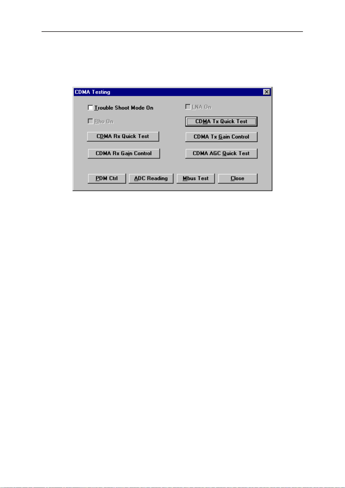
WinTesla User Guide
PAMS
NHD–4
CDMA Testing
This screen is used when testing and troubleshooting the phone in CDMA
mode. Below is an example screen.
Keys:
Technical Documentation
PDM Ctrl – Opens the PDM Control Screen.
ADC Reading – Opens the ADC reading screen.
Quick RX Test – Opens the Quick Receiver test screen.
Mbus Test – Tests the communication between the phone and the
computer.
Close – Exits the current screen.
RHO on:
RHO on – turns the CDMA transmitter on/off.
LNA on:
LNA on – turns the CDMA receiver’s Low Noise Amplifier on/off.
Troubleshooting mode on:
Troubleshooting Mode on – will set the phone into CDMA mode for
technical troubleshooting. This mode is the Local mode for CDMA.
CDMA TX Bias Tuing Functionality Test
Manual Test
To verify this functionality manually, complete the CDMA TX Bias tuning in
the Service Software, or perform the following steps:
1. Initiate the CDMA TX Manual Gain controls from the CDMA Test menu
located in the Service Software.
2. Set the CDMA TX Gain to minimum. There should be less than –30
dBm of CDMA output band power.
Page 58
Original 11/97
Page 59

PAMS
WinTesla User Guide
Technical Documentation
3. Set the TXB PDM to 128 decimal. This will provide minimum bias to the
CLY–10 (V113).
4. Read the total current draw of the phone. The phone should draw
between 380 and 480 mA, generally about 430 mA. Record this current
value as the CDMA Mode Quiescent Current.
5. Initiate the CDMA Troubleshooting Mode from the Test menu of the
Service Software.
6. Using the PDM controls Adjust the TX_OFFSET PDM until the output
bandpower is –8 dBm.
7. Again use the CDMA TX Manual Gain controls located in the CDMA
tests selection of the Test menu.
8. Use this control to achieve approximately 10 dBm of CDMA TX output
bandpower.
9. From the PDM controls, adjust the TXB PDM until the total current draw
of the phone is 100 mA greater than the CDMA Mode Quiescent Current,
determined in step 4. Accomplishing this, verifies Low CDMA TX Power
Bias.
NHD–4
10. Repeat steps 3 – 5, but for 23 dBm of CDMA TX output bandpower,
and 250 mA of current over the CDMA Mode Quiescent Current,
determined in step 4. Accomplishing this verifies Max CDMA TX Power
Bias.
Troubleshooting
A failure of this test could be attributed to a number of things. Foremost,
both the transmitter and the synthesizer have to be functional. The TXB
PDM is adjusted throughout this tuning, as is the TX Offset PDM. Ensure
their operation. The negative voltage generator N200 and the VTXS
supply should also be inspected for proper operation. If these tunings is
unable to achieve the minimum amount of bias currents there may be a
faulty, misplaced or wrong value component in the bias circuitry
supporting the CLY–10.
TX Gain Limiting Tuning Functionality Test
Manual Test
The CDMA TX Gain Limiting functionality can be verified by performing
the TX Gain Limiting tuning procedure found in the tuning menu of the
Service Software. Another option is to perform the steps below:
1. Initiate the CDMA TX Manual Gain controls from the CDMA Test menu
located in the Service Software.
2. Set the CDMA TX Gain to maximum.
3. From the PDM controls, adjust the TXI_REF PDM to 127 decimal. The
phone should achieve approximately 27 dBm of CDMA output bandpower.
Original 11/97
Page 59
Page 60

WinTesla User Guide
PAMS
NHD–4
4. Adjust the TXI_REF PDM until the CDMA TX output bandpower is
approximately 24.5 dBm. If this can be accomplished, the TX Gain
Limiting functionality has been verified.
Troubleshooting
A failure of this test might result from a faulty transmitter, or problems
within the CDMA TX gain control circuitry. The operation of the CDCONT
should be checked, as should the TXI_REF PDM, and the TXI voltage. If
the transmitter has lost any gain, this test will most likely fail.
Aux. AGC Tuning Functionality Test
Manual Test
Auxiliary AGC functionality can be verified by performing the Aux. AGC
tuning from the Service Software. Another method would be to perform
the manual verification steps described below.
1. Maximize the CDMA TX output bandpower by initiating the CDMA
Troubleshooting Mode.
Technical Documentation
2. From the PDM controls, adjust the AGC_REF PDM to 0. This sets the
AT–109 to minimum attenuation.
3. Next adjust the TX_OFFSET PDM until the CDMA TX output
bandpower is approximately 16 dBm. This verifies the BPOW1 step
4. Adjust the AGC_REF PDM to provide the 5 dB of attenuation, bring the
output bandpower to approximately 11.0 dBm. This verifies the next step
BPOW1 – BPOW2.
5. Adjust the AGC_REF PDM to provide an additional 10 dB of
attenuation, bring the output bandpower to approximately 1.0 dBm. If the
additional 10 dB of attenuation is achieved, the third step BPOW2 –
BPOW3 is verified. The final 1.0 dBm bandpower is BPOW3.
Troubleshooting
For this step to occur the CDMA transmitter must be functioning, at least
enough to achieve 16 dBm of output. The TX_OFFSET and AGC_REF
PDMs must work, as well as the AT–109 attenuator. Consult the Service
Manual
for further information and tests.
Transmitter Troubleshooting section and Functional Description
Page 60
Original 11/97
Page 61

PAMS
WinTesla User Guide
Technical Documentation
LNA Gain Calibration Functionality Test
Manual Test
The LNA Gain Calibration process can be verified by performing the
associated procedure found in the tuning menu of the Service Software. It
can also be verified manually by performing the following steps:
1. Initiate the CDMA RX Quick Test from the test menu of the Service
Software
2. Into the CDMA RX feed a –65 dBm CW signal at 881.62 MHz
3.Turn the LNA on from this window
4. Read the received power to the CDSB ASIC, the RxCtr, by hitting the
“Test” button. Record this value.
5. Turn the LNA off
NHD–4
6. Again read the received power to the CDSB ASIC, the RxCtr, by hitting
the “Test” button. Record this value.
7. If the LNA is operating correctly the difference between the two
recorded values will fall between 120 and 160.
Troubleshooting
Fault with this calibration obviously points suspicion to the LNA
functionality. The CDMA RX may also be at fault. Also inspect the RF
switches N701 and N702 as well as the resistive attenuator located
between them. The Service Manual Receiver Troubleshooting section
and Functional Description will provide further information and test
suggestions to troubleshoot this fault.
CDMA TX Spurious Check
Definition of Test
This test reads spurious emissions levels of the CDMA Transmitter +/–
900 kHz from the center of the channel. For this test the phone is
transmitting at its maximum level in CDMA mode. This test can be
performed manually with a spectrum analyzer. To do this feed the 2180
RF output into the spectrum analyzer and set the CDMA TX output to
maximum. Service Software rails the CDMA TX to maximum for the
CDMA TX Quick Test. I recommend using it to put the phone into the
proper mode. Use the averaging functionality of the spectrum analyzer to
get readings of better precision. Set a marker + 30 kHz off the center
frequency of the transmit signal. Set another marker + 900 kHz off the
center frequency. The delta between them should be at least 26 dB. This
should also be done for – 30 and –900 kHz off center.
Original 11/97
Page 61
Page 62

WinTesla User Guide
PAMS
NHD–4
Manual Verification
Spurious emissions of the CDMA transmitter can be read manual using a
spectrum analyzer. To do so perform the following steps:
1. Feed the RF output of the phone into the spectrum analyzer.
2. Set the CDMA TX output power to maximum using the manual TX gain
controls. The Service Software also rails the CDMA TX to maximum for
the CDMA TX Quick Test.
3. Set the Resolution Bandwidth of the spectrum analyzer to 30 kHz. Use
the averaging functionality of the spectrum analyzer to get readings of
better precision.
4. Set a marker + 30 kHz off the center frequency of the transmit signal.
5. Set another marker + 900 kHz off the center frequency.
6. The delta between the two markers should be at least 26 dB.
7. Repeat this test with markers –30 kHz and –900 kHz off the center
frequency.
Technical Documentation
The resultant value reported from the automated tester is the power
difference (delta) in dB between the 30 kHz and 900 kHz frequency offset
positions, as described above
Troubleshooting
The CDMA transmitter must be functioning properly to correctly perform
this test. The maximum power level of the CDMA TX must be correct,
approximately 24 dBm. The operation of the CDAGCT IC (N100) and the
AT–I09 attenuator IC (V106) greatly influence the results of this test.
Should this test fail, it is suggested that their health and functionality be
inspected. The Service Manual Transmitter Troubleshooting section and
Functional Description will provide information and tests for the transmitter
chain.
LNA Gain Calibration
Definition of Test
This operation determines the gain differential of the receiver system with
the LNA on and off. The CDMA receiver system is then calibrated
accordingly. To do this a constant level CW tone is fed into the CDMA
receiver. The LNA is turned on and the received signal strength to the
CDSB ASIC (D704) is read and stored. This is the also known as the
RxCtr value. With the same input signal the LNA is then turned off and
the RxCtr is read again. The dB power difference between the two RxCtr
values is equivalent to the gain that the LNA provides.
Page 62
Original 11/97
Page 63

PAMS
WinTesla User Guide
Technical Documentation
Troubleshooting
Fault with this calibration obviously points suspicion to the LNA
functionality. The CDMA RX may also be at fault. The Service Manual
Receiver Troubleshooting section and Functional Description will provide
further information and test suggestions to troubleshoot this fault.
NHD–4
Original 11/97
Page 63
Page 64

WinTesla User Guide
PAMS
NHD–4
Software Menu
The Software menu provides the following options:
Flashing
Technical Documentation
This option allows you Reflash a phone with a new version of flash
software, enabling new features to be added and bugs to be removed.
This Reflash option relies on the phone being in full working order and
containing the correct HWID and Product Code.
Note: To successfully update the flash code, the Nokia FPS–3C MUST be
connected to the PC that is running the WinTesla software. (see mechanical
connections in the service manual for details)
Caution: The computer that is connected to the FPS–3C Flash box
MUST have it’s parallel port configuration set to standard AT
type. Otherwise downloading the flash image to the “black box”
will fail.
Reflashing summary:
– Ensure the computers parallel port is configured properly.
– Select ”Software – Flash”
– Select the correct flash file to be flashed to the phone.
– Set Flash options in dialog box.
– Press the <Flash> key.
Dialog Options
Each of the options available are described below. It is suggested that
only experienced operators change these settings from there default
values.
Page 64
Original 11/97
Page 65

PAMS
WinTesla User Guide
Technical Documentation
File size selection
Changes the size parameters for the flash file. Default value is 8 Meg bits.
Check box – set phone to minimum mode
Automatically sets the phone to minimum mode. If not set, the operator
must “force” the phone to this mode using hardware.
Check box – Keep RF parameters
This option will save the RF parameters before flashing the phone. Once
flash updating is complete, these parameters will be stored back to the
phone.
Check box – Keep User Data
This option will save user data before flashing the phone. Once flash
updating is complete, the user data will be saved back into the phone.
USER DATA SAVED:
NHD–4
– Short Code Memory
– NAM programming information
– Calling Card Numbers
– SID Lists
– System Feature codes
– UI Settings
– Warranty Information
Check box – Initialize EEPROM after Flash
This option will prompt for initialization of the EEPROM after flash
updating is complete. It is recommended that the EEPROM be
“Initialized“ after flash updating the phone. (
more details on this function
Check box – Skip download to Flash box
The flash update is done using a two step process. the flash image is
downloaded to the flash box in the first step. This takes about 30 to 45
seconds. Then the image is updated on the phone during the second
step.
)
see Initialize EEPROM for
This option is useful if you are updating several phones with the same
flash image. After completing the first phone update, checking this option
will skip the first step of downloading the flash image to the box again. It
is not necessary to download the image again because the box will
contain the last image loaded unless a loss of power occurs.
Original 11/97
Page 65
Page 66

WinTesla User Guide
PAMS
NHD–4
Initialize EEPROM
This option will re–initialize the phone’s EEPROM settings.
CAUTION: All the phone’s calibrated (tuned) data will be erased by this option and the
phone MUST now be recalibrated.
Technical Documentation
Product Data
This option will reset the Product data.
UI Data
This option will reset the user interface data.
SCM Data
This option will reset the short code memory data.
SMS Data
This option will reset the short messaging services data.
All of the above
This option will reset all of the above.
View RF Parameters
Opens the RF parameters dialog for viewing this data.
Page 66
Original 11/97
Page 67

PAMS
WinTesla User Guide
Technical Documentation
Dealer Menu
NAM Programming
NHD–4
This option allows you to program the NAM information, wake up
message, Emergency numbers, Lock code and security code of the
phone.
Keys:
NAM Selection
Selects NAM contents to be displayed.
Load File
Prompts user to select a file containing NAM information.
Save File
Allows user to save screen contents to a file.
Read Phone
Reads phone contents to screen.
Write Phone
Writes contents of screen to phone.
Original 11/97
Page 67
Page 68

WinTesla User Guide
PAMS
NHD–4
Technical Documentation
Default NAM Parameter Settings
These settings apply to both NAM 1 and NAM 2 unless stated otherwise. Values are shown in
decimal format.
Parameter Default Setting Valid Values
Own Number (Phone No. associated
with NAM, more specifically known as
the MIN)
Home SID List SID 1 = Home System ID;
Access Overload Class last number of MIN 0 – 15
NAM Status NAM 1: Enabled;
Group ID 10 0 – 15
Access Method 1 0,1
Local Use Mark 1 0,1
Country Code 0 0 – 999
Network Code 0 0 – 99
Directory Number (Phone No. associat-
ed with NAM, more specifically known
as the MDN)
AMPS Paging Channel If the HOME SYSTEM ID set-
000 000 XXXX (where XXXX
is the last 4 digits of ESN)
All other SIDs are empty.
NAM 2: Disabled
000 000 XXXX (where XXXX
is the last 4 digits of ESN)
ting is odd, the A type channel default is used. If it is
even, the B type paging channel default is used.
10 digits;
1 – 32767 for each SID.
Up to 4 unique SIDs
Enabled/Disabled
10 digits;
0 – 2047
A type channel: 333
B type channel: 334
Primary CDMA Channel A 283 1 – 311
Secondary CDMA Channel A 691 689 – 694
Primary CDMA channel B 384 356 – 644
Secondary CDMA channel B 777 739 – 777
Emergency Numbers 911, *911, empty .
Lock Code 1234
Security Code 12345
Page 68
Original 11/97
Page 69

PAMS
WinTesla User Guide
Technical Documentation
Short Code Memory (SCM)
NHD–4
This option allows the user to change the phone directory numbers (also
known as short code memory).
Keys:
Close
Closes Short Code memory screen.
Load File
Prompts user to select a file containing Short Code Memory information.
Save File
Allows user to save screen contents to a file.
Read Phone
Reads phone contents to screen.
Write Phone
Writes contents of screen to phone.
Edit
Edits the highlighted entry.
Delete
Deletes the highlighted entry.
Original 11/97
Page 69
Page 70

WinTesla User Guide
PAMS
NHD–4
SID Programming
This option allows you to edit the SID list. Highlight an entry using the
<TAB> key and press enter to edit.
Technical Documentation
Keys:
Load File
Prompts user to select a file containing SID information.
Save File
Allows user to save screen contents to a file.
Read Phone
Reads phone contents to screen.
Write Phone
Writes contents of screen to phone.
Page 70
Original 11/97
Page 71

PAMS
WinTesla User Guide
Technical Documentation
Calling Cards
NHD–4
This option allows the user to program the calling card information into the
phone.
Card Name
Allows user to change the name of the calling card display in the phones
menu.
Access Method
Allows user to select the appropriate method for connecting with the
service providers network according to the calling card requirements.
Please contact your service provider for details or the calling card
instructions. Changing this setting causes the phone to execute the
sequence of events according to option choosen.
– Access/Phone/Card – sends the service providers Access
number, then the Phone number being dialed by user, then
Calling Card number.
– Access/Card/Phone – sends the service providers Access
number, then Calling Card number, then the Phone number
being dialed by user.
Access Number
The number used to access the service provders network. Typically a toll
free number.
Original 11/97
– Prefix/Phone/Card – sends the service providers Prefix
number (typically a zero), then the Phone number being
dialed by user, then Calling Card number
Page 71
Page 72

WinTesla User Guide
PAMS
NHD–4
Card Number
Also known as “card ID”, this number is the actual calling card number
issued by the service provider.
Prefix
This number is sent to gain system access. Typically a zero.
International Prefix
Currently not used.
National Prefix
Currently not used.
Authentication Key (A–Key) Programming
Technical Documentation
This option allows you to program the Authentication key of the phone.
The A–key can
phone over writing the previous value.
To program the A–key a valid A–key plus a valid checksum must be
entered as one complete number.
Example:
Keys:
Write Selected
Writes the highlighted selection to the selected NAM in the phone if A–Key
is valid. Otherwise an error message is displayed.
Write All
Writes both A–Key numbers to the corresponding NAM of the phone if the
A–Key is valid. Otherwise an error message is displayed.
never
– Valid A–Key number= 6 to 20 digits (e.g. XXXXXXXXXX)
– Valid checksum = 6 digits (e.g. YYYYYY)
– A–Key Entry would be XXXXXXXXXXYYYYYY
be read from the phone, only programmed to the
Page 72
Original 11/97
Page 73
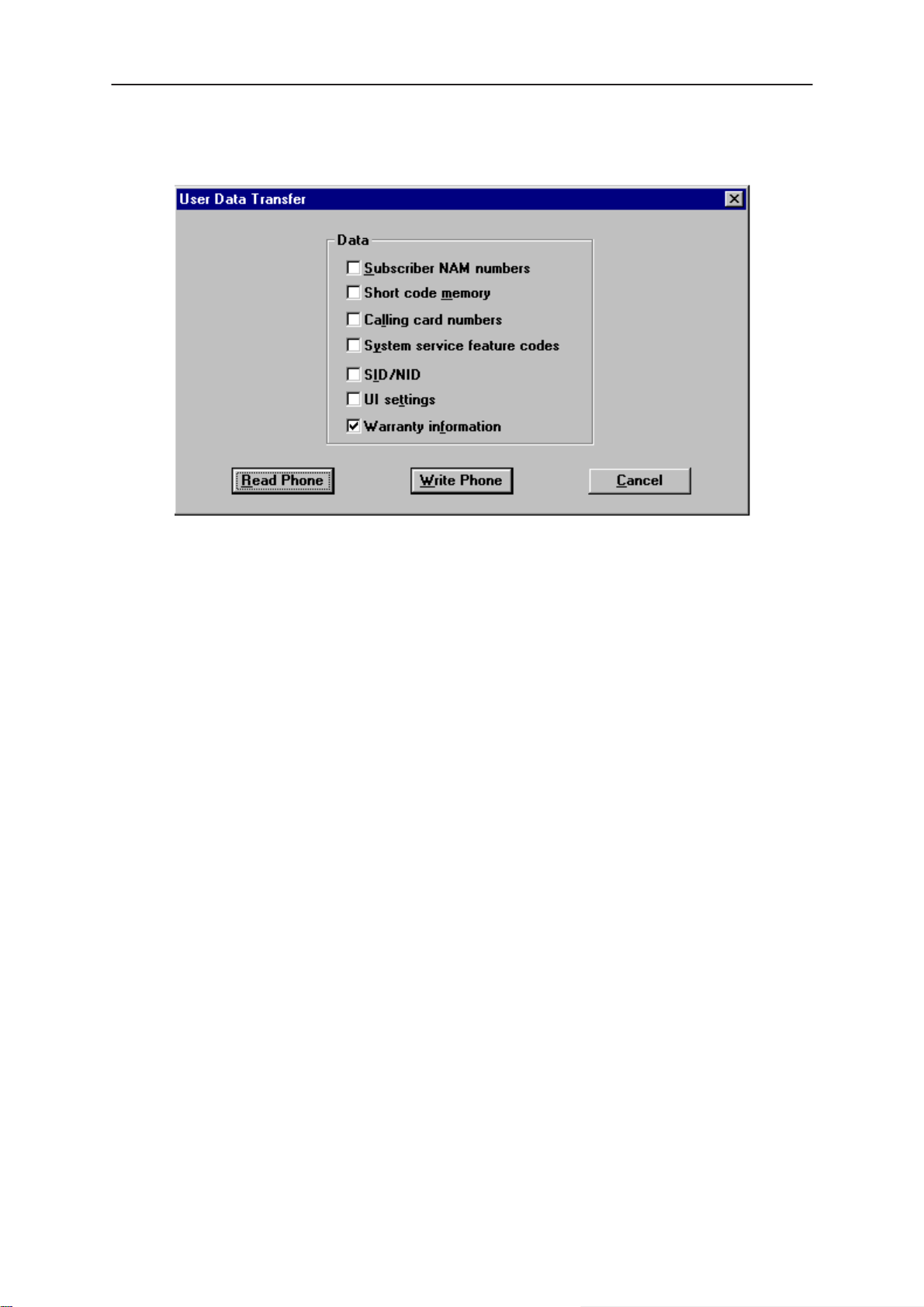
PAMS
WinTesla User Guide
Technical Documentation
User Data Transfer
This option allows you to transfer the selected user data from one phone
to another.
NHD–4
Note: The Warranty Information can not be unchecked and will always be
transferred. The information can on;y be transferred to a phone once. After that an error
dialog is displayed.
If a phone should need to be replaced at the point of return, this option will
read the selected information from the defective phone, allow the user to
change to a new (replacement) phone, and write the users data into the
replacement unit.
Steps involved
– With phone powered on, Connect defective unit and press
<Read Phone>.
– Disconnect defective unit.
– Connect replacements unit and power on.
– Press <Write Phone>.
Original 11/97
Page 73
Page 74
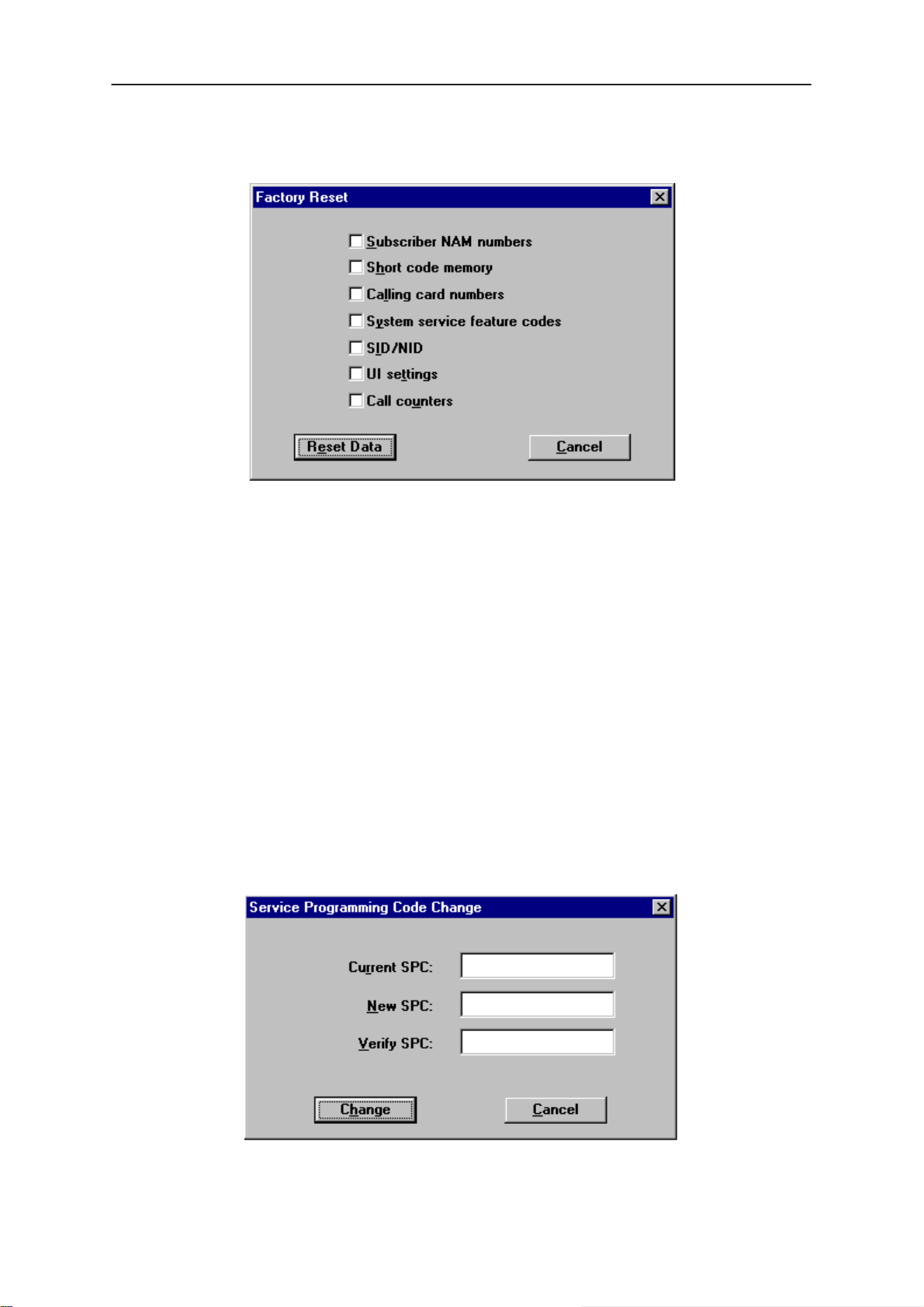
WinTesla User Guide
PAMS
NHD–4
Set Factory Values
This option allows you to reset a phone’s settings to their initial (factory)
default values. The phone is also re–product profiled based on the
product code.
Technical Documentation
The following list is a subset of data which can be reset to factory defaults:
– NAM information
– Clear Short Code Memory
– Calling Card information
– System Feature Codes
– System ID lists
– User Menu Settings
– Call Counters (except Life time counter)
Note: This option will NOT erase any calibrated values within the phone.
SPC code change
Page 74
This option allows you to change the Subscriber Programming Code
(SPC) if the original code is known.
Original 11/97
Page 75
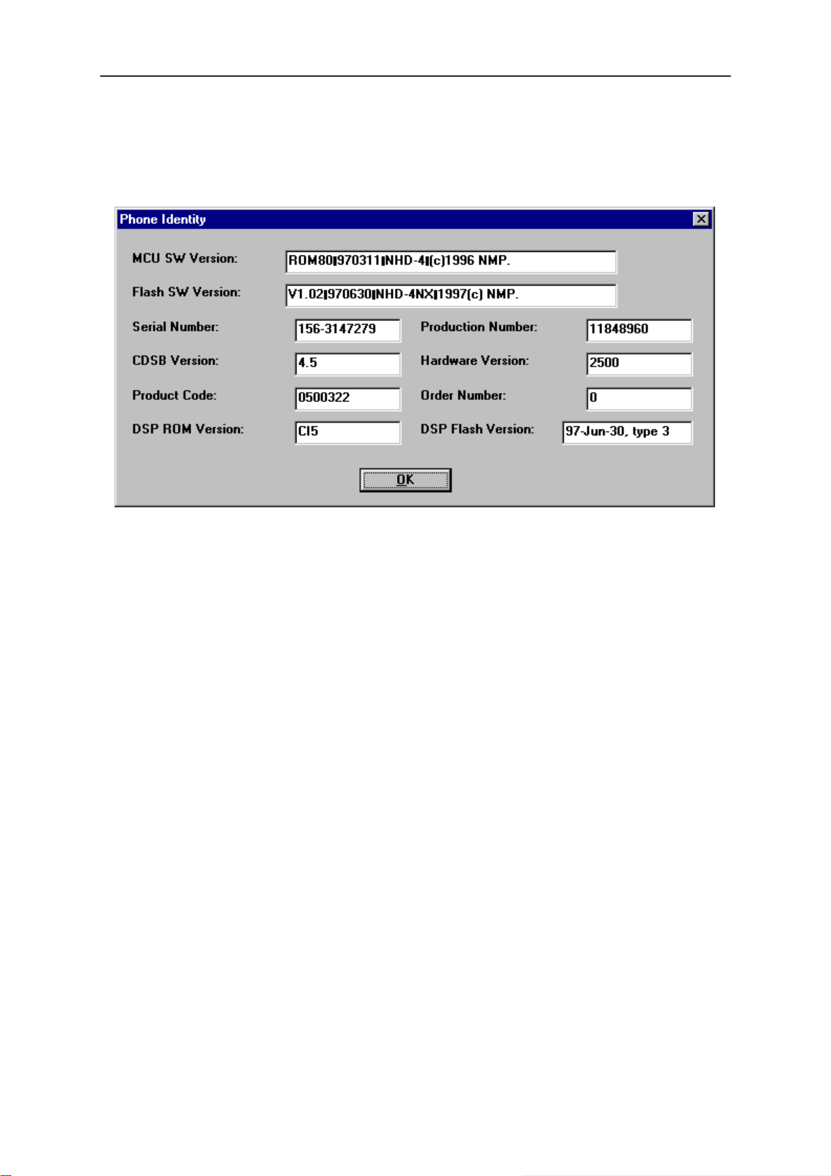
PAMS
WinTesla User Guide
Technical Documentation
View Menu
Phone Identity
NHD–4
This option displays the following phone identity fields:
– ROM version
– Flash version
– Production Serial Number (PSN),
– Order Number,
– Product Code,
– Hardware ID.
Original 11/97
Page 75
Page 76

WinTesla User Guide
PAMS
NHD–4
RF Parameters
Technical Documentation
This dialog shows the RF parameters of the phone. Looking at these
parameters can help the technician in making decisions about the status
of the phone.
Page 76
Original 11/97
Page 77
PAMS
WinTesla User Guide
Technical Documentation
Help
Index
A comprehensive list of all WinTesla features, hypertext linked.
General Help (F1)
This option contains two options:
– Help on using WinTesla
– Help on using Help
Using Help
This option provides you with information on using the online help
function.
About WinTesla
Displays information on the the version that is running.
NHD–4
Original 11/97
Page 77
Page 78

WinTesla User Guide
PAMS
NHD–4
Common Problems
This section is a reference of known commo problems that may be
encountered when working with the Wintesla software package.
Setting up the computer Hardware
In order to avoid some common hardware problem, please ensure the
computer hardware is set up as follows.
COM Port Set up
COM port address (COM1 or COM2) should be set as the default values
for these ports. Special port address or IRQ settings may encounter
problems. to test this case set up a COM port as the default values and
try running the Wintesla application again.
Printer port set up
The printer port is used to attach the PKD–1 software Protection Key.
This device should work properly with most printer port settings. However,
if a problem is encountered, change the computer printer port (LPT–1)
setting to “Standard AT type”. This is NOT a Bi–directional setting.
Technical Documentation
NOTE: When using an FPS–3C flash programming set, the printer port MUST be set
as “Standard AT Type”. The Flash box (FPS–3C) must have power connected.
Common Errors
Error – Functionality DLL not found
This error will be encountered if a phone is connected to WIntesla and it is
not recognized.
Solution
Install the Service Module for the phone type connected to Wintesla.
Contact your local Nokia vendor for information on how to obtain this
Service Module.
Error – PKD–1 not found
PKD–1 is the software Protection Key Device that is required for the
Wintesla application to run. This error will be encountered if the PKD–1
device is not installed on your printer port (LPT–1).
Solution
Page 78
Attach the PKD–1 to the printer port (LPT–1) of the PC running Wintesla.
Original 11/97
Page 79

PAMS
WinTesla User Guide
Technical Documentation
Error – System hangs or Locks up
Wintesla may hang or Lock up if it is being run on Windows 95 or NT.
Solution
Run the Wintesla application on Windows 3.1 or 3.11. The Wintesla
application is NOT designed to run under Windows 95 or NT. If you are
using Windows 3.1 or 3.11 and are still experiencing problems please call
your local Authorized Service & Support location.
Error – Reset FPS–3 box
This error only occurs when reflashing a phone with new software.
Solution
Remove power from the FPS–3C box for approximately 5 seconds. Then
reconnect power.
NHD–4
Error – Phone will not Tune properly
The phone can not be properly Tuned while connected to the FPS–3C
flash box. The voltage coming from the box will cause errors in the tuning
parameters.
Solution
Disconnect the FPS–3C box from the phone while Tuning. Only use one
of the set up configurations listed in the Dealer Setups section of the
NHD–4NX Service Manual.
Service and Support
Please contact your local Service location for more information and
support .
Or try our web site (http://www.Nokia.com)
Original 11/97
Page 79
Page 80

WinTesla User Guide
PAMS
NHD–4
Technical Documentation
[This page intentionally left blank]
Page 80
Original 11/97
 Loading...