

Page 1

Programmes After Market Services
WinTesla Users Guide
NHP–4
Issue 1 04/99
Page 2

WinTesla Users Guide
PAMS
NHP–4
Technical Documentation
Contents
Tesla for Windows Operating System 5. . . . . . . . . . . . . . . . . . . . . . . . . . . . . . .
Installing WinTesla On Your Hard Disk 5. . . . . . . . . . . . . . . . . . . . . . . . . . . . . .
Using The Windows Interface 5. . . . . . . . . . . . . . . . . . . . . . . . . . . . . . . . . . . . . .
Common User Interface 5. . . . . . . . . . . . . . . . . . . . . . . . . . . . . . . . . . . . . . . . . . .
Equipment Required 6. . . . . . . . . . . . . . . . . . . . . . . . . . . . . . . . . . . . . . . . . . . . . .
Mechanical Connections 6. . . . . . . . . . . . . . . . . . . . . . . . . . . . . . . . . . . . . . . . . .
Using Wintesla 7. . . . . . . . . . . . . . . . . . . . . . . . . . . . . . . . . . . . . . . . . . . . . . . . . . .
Phone Independence 7. . . . . . . . . . . . . . . . . . . . . . . . . . . . . . . . . . . . . . . . . .
Login ID Setup 8. . . . . . . . . . . . . . . . . . . . . . . . . . . . . . . . . . . . . . . . . . . . . . . .
The Login Screen 9. . . . . . . . . . . . . . . . . . . . . . . . . . . . . . . . . . . . . . . . . . . . .
The WinTesla Screen 10. . . . . . . . . . . . . . . . . . . . . . . . . . . . . . . . . . . . . . . . . .
The Product Menu 11. . . . . . . . . . . . . . . . . . . . . . . . . . . . . . . . . . . . . . . . . . . . .
Page No
The Configure Menu 12. . . . . . . . . . . . . . . . . . . . . . . . . . . . . . . . . . . . . . . . . . .
Fault Log Application. 16. . . . . . . . . . . . . . . . . . . . . . . . . . . . . . . . . . . . . . . . . .
Help 20. . . . . . . . . . . . . . . . . . . . . . . . . . . . . . . . . . . . . . . . . . . . . . . . . . . . . . . . .
HD891 Module 20. . . . . . . . . . . . . . . . . . . . . . . . . . . . . . . . . . . . . . . . . . . . . . . . . . .
Installing the HD891 Service Module 20. . . . . . . . . . . . . . . . . . . . . . . . . . . . . . . .
Required Servicing Equipment 21. . . . . . . . . . . . . . . . . . . . . . . . . . . . . . . . . .
Equipment Setup 22. . . . . . . . . . . . . . . . . . . . . . . . . . . . . . . . . . . . . . . . . . . . . .
Dealer Setups 23. . . . . . . . . . . . . . . . . . . . . . . . . . . . . . . . . . . . . . . . . . . . . . . .
Main Menu 25. . . . . . . . . . . . . . . . . . . . . . . . . . . . . . . . . . . . . . . . . . . . . . . . . . .
Product 25. . . . . . . . . . . . . . . . . . . . . . . . . . . . . . . . . . . . . . . . . . . . . . . . . . . . . .
Configure 25. . . . . . . . . . . . . . . . . . . . . . . . . . . . . . . . . . . . . . . . . . . . . . . . . . . .
Tuning Steps of Radio Unit 26. . . . . . . . . . . . . . . . . . . . . . . . . . . . . . . . . . . . . . . .
Accuracy of the Equipment During Measurement 26. . . . . . . . . . . . . . . . . .
Baseband Alignment and Flash Station Tests 26. . . . . . . . . . . . . . . . . . . . . . . .
Flash Programming 26. . . . . . . . . . . . . . . . . . . . . . . . . . . . . . . . . . . . . . . . . . . .
Factory Value Set 27. . . . . . . . . . . . . . . . . . . . . . . . . . . . . . . . . . . . . . . . . . . . .
Battery Voltage Tuning 27. . . . . . . . . . . . . . . . . . . . . . . . . . . . . . . . . . . . . . . . .
Charger Voltage Tuning 28. . . . . . . . . . . . . . . . . . . . . . . . . . . . . . . . . . . . . . . .
RF Temperature Tuning 28. . . . . . . . . . . . . . . . . . . . . . . . . . . . . . . . . . . . . . . .
RF Tuning and Testing 29. . . . . . . . . . . . . . . . . . . . . . . . . . . . . . . . . . . . . . . . . . . .
CDMA Bias Quiescent Current Test 29. . . . . . . . . . . . . . . . . . . . . . . . . . . . . .
AFC Tuning 29. . . . . . . . . . . . . . . . . . . . . . . . . . . . . . . . . . . . . . . . . . . . . . . . . .
RX AGC Tuning and Dynamic Range Check 30. . . . . . . . . . . . . . . . . . . . . .
TX Gain Check 31. . . . . . . . . . . . . . . . . . . . . . . . . . . . . . . . . . . . . . . . . . . . . . .
TX IF AGC Tuning and Dynamic Range Check 31. . . . . . . . . . . . . . . . . . . .
Page 2
Issue 1 04/99
Page 3

PAMS
WinTesla Users Guide
Technical Documentation
TX Limiting, TX Emissions, and Frequency Compensation 32. . . . . . . . . .
Open–Loop AGC Alignment 33. . . . . . . . . . . . . . . . . . . . . . . . . . . . . . . . . . . .
Testing 34. . . . . . . . . . . . . . . . . . . . . . . . . . . . . . . . . . . . . . . . . . . . . . . . . . . . . . . . . .
Self Tests 34. . . . . . . . . . . . . . . . . . . . . . . . . . . . . . . . . . . . . . . . . . . . . . . . . . . .
ADC Readings 34. . . . . . . . . . . . . . . . . . . . . . . . . . . . . . . . . . . . . . . . . . . . . . . .
Pulse Division Modulator (PDM) Control 35. . . . . . . . . . . . . . . . . . . . . . . . . .
CDMA Testing 36. . . . . . . . . . . . . . . . . . . . . . . . . . . . . . . . . . . . . . . . . . . . . . . . . . .
CDMA RX Quick Test 36. . . . . . . . . . . . . . . . . . . . . . . . . . . . . . . . . . . . . . . . . .
CDMA RX Gain Control 37. . . . . . . . . . . . . . . . . . . . . . . . . . . . . . . . . . . . . . . .
Reset Phone 37. . . . . . . . . . . . . . . . . . . . . . . . . . . . . . . . . . . . . . . . . . . . . . . . .
TX Limiting 37. . . . . . . . . . . . . . . . . . . . . . . . . . . . . . . . . . . . . . . . . . . . . . . . . . .
CDMA TX Gain Control 37. . . . . . . . . . . . . . . . . . . . . . . . . . . . . . . . . . . . . . . .
CDMA AGC Quick Test 37. . . . . . . . . . . . . . . . . . . . . . . . . . . . . . . . . . . . . . . .
Software Menu 38. . . . . . . . . . . . . . . . . . . . . . . . . . . . . . . . . . . . . . . . . . . . . . . . . . .
Flashing 38. . . . . . . . . . . . . . . . . . . . . . . . . . . . . . . . . . . . . . . . . . . . . . . . . . . . .
NHP–4
Dialog Options 38. . . . . . . . . . . . . . . . . . . . . . . . . . . . . . . . . . . . . . . . . . . . . . . .
Initialize EEPROM 40. . . . . . . . . . . . . . . . . . . . . . . . . . . . . . . . . . . . . . . . . . . . .
Dealer Menu 41. . . . . . . . . . . . . . . . . . . . . . . . . . . . . . . . . . . . . . . . . . . . . . . . . . . . .
NAM Programming 41. . . . . . . . . . . . . . . . . . . . . . . . . . . . . . . . . . . . . . . . . . . .
Short Code Memory (SCM) 43. . . . . . . . . . . . . . . . . . . . . . . . . . . . . . . . . . . . .
SID Programming 44. . . . . . . . . . . . . . . . . . . . . . . . . . . . . . . . . . . . . . . . . . . . .
Calling Cards 45. . . . . . . . . . . . . . . . . . . . . . . . . . . . . . . . . . . . . . . . . . . . . . . . .
Authentication Key (A–Key) Programming 46. . . . . . . . . . . . . . . . . . . . . . . .
User Data Transfer 47. . . . . . . . . . . . . . . . . . . . . . . . . . . . . . . . . . . . . . . . . . . .
Set Factory Values 48. . . . . . . . . . . . . . . . . . . . . . . . . . . . . . . . . . . . . . . . . . . .
SPC code change 48. . . . . . . . . . . . . . . . . . . . . . . . . . . . . . . . . . . . . . . . . . . . .
View Menu 49. . . . . . . . . . . . . . . . . . . . . . . . . . . . . . . . . . . . . . . . . . . . . . . . . . . . . .
Phone Identity 49. . . . . . . . . . . . . . . . . . . . . . . . . . . . . . . . . . . . . . . . . . . . . . . .
RF Parameters 50. . . . . . . . . . . . . . . . . . . . . . . . . . . . . . . . . . . . . . . . . . . . . . .
Help 51. . . . . . . . . . . . . . . . . . . . . . . . . . . . . . . . . . . . . . . . . . . . . . . . . . . . . . . . . . . .
Common Problems 52. . . . . . . . . . . . . . . . . . . . . . . . . . . . . . . . . . . . . . . . . . . . . . .
Setting up the computer Hardware 52. . . . . . . . . . . . . . . . . . . . . . . . . . . . . . .
Common Errors 52. . . . . . . . . . . . . . . . . . . . . . . . . . . . . . . . . . . . . . . . . . . . . . .
Service and Support 53. . . . . . . . . . . . . . . . . . . . . . . . . . . . . . . . . . . . . . . . . . . . . .
Issue 1 04/99
Page 3
Page 4

WinTesla Users Guide
PAMS
NHP–4
Technical Documentation
List of Figures
Figure 1. Dongle Insertion 6. . . . . . . . . . . . . . . . . . . . . . . . . . . . . . . . . . . . . . . .
Figure 2. Servicing setup 7. . . . . . . . . . . . . . . . . . . . . . . . . . . . . . . . . . . . . . . .
Figure 3. Flash setup 7. . . . . . . . . . . . . . . . . . . . . . . . . . . . . . . . . . . . . . . . . . . .
Figure 4. WinTesla with loaded interfaces 8. . . . . . . . . . . . . . . . . . . . . . . . . .
Figure 5. Accessing Op_ID. val file 8. . . . . . . . . . . . . . . . . . . . . . . . . . . . . . .
Figure 6. Editing Op_ID.val file 9. . . . . . . . . . . . . . . . . . . . . . . . . . . . . . . . . . .
Figure 7. Login Screen 9. . . . . . . . . . . . . . . . . . . . . . . . . . . . . . . . . . . . . . . . . .
Figure 8. FaultLog – configuration 15. . . . . . . . . . . . . . . . . . . . . . . . . . . . . . . . .
Figure 9. Editing fault, symptoms, modules files 18. . . . . . . . . . . . . . . . . . . . .
Figure 10. FaultLog – macro setup 19. . . . . . . . . . . . . . . . . . . . . . . . . . . . . . . .
Figure 11. Testing/Tuning with covers off 23. . . . . . . . . . . . . . . . . . . . . . . . . . .
Figure 12. Testing/Tuning with covers on 24. . . . . . . . . . . . . . . . . . . . . . . . . . .
Page No
Page 4
Issue 1 04/99
Page 5

PAMS
WinTesla Users Guide
Technical Documentation
Tesla for Windows Operating System
The name TESLA, when used by Nokia, is an acronym for TEst and
Service Locals Application. Tesla for WIndows (i.e. WinTesla) is a
software package designed to operate in the Microsoft Windows
environment. The software package is made of two modules, the
Wintesla core module and a service software module. The Wintesla
module is similar to an operating system for various service modules. In
this way many Nokia products can be serviced using one common
software package, running different service modules (in this case, for the
Nokia 2170).
Note: The Wintesla core module MUST be installed for ”any” service module to run.
Installing WinTesla On Your Hard Disk
The WinTesla core software is delivered on a 3.5” diskette and is
protected with a protection key (PKD–1, commonly referred as the
”dongle”) which must be attached to the parallel port LPT 1 when the
WinTesla service software is being used.
NHP–4
To install the WinTesla core software package, proceed as follows:
NOTE: For instructions on installing the HD891 service module (see Installing the
HD891 Service Module)
Insert the WinTesla Application diskette into drive A: of your PC.
From DOS ( NOT running windows ) type
A: INSTALL <Enter>
From Windows File Manager double click the mouse on
a:\install.exe
Follow the instructions given and use the
Repeat this procedure for the required module installation using the
upgrade
NOTE: For interim WinTesla releases use the upgrade option.
Your Windows desktop will now have a “Service Software” group and a
“Service Software” icon within that group.
To start the program, double click on the “Service Software” icon .
option instead of
(Windows will boot up automatically)
Or
new
.
Using The Windows Interface
new
option when requested.
If not familiar with the windows type interface, consult the
Windows User Guide
for further information.
Common User Interface
Due to the modular design of WinTesla, various generations of Nokia
products can be serviced, while sharing a similar user interface. The
common user interface is explained in the first part of this document and
is followed by the specific module information.
The software can be used to control the phone by entering commands via
the keyboard of a PC/AT – running MS Windows 3.1 or 3.11.
Issue 1 04/99
Microsoft
Page 5
Page 6
WinTesla Users Guide
PAMS
NHP–4
NOTE:
This document refers to WinTesla Version 4.60 or greater.
Windows 95 and Windows NT are not supported.
Equipment Required
Computer : IBM 486 PC/AT or compatible with at least
one, unused serial port, COM1 or COM2 one parallel port
(LPT1), 5 Meg. hard disk space required.
: Any supported by MS Windows version 3.1 or 3.11
Operating System : DOS 5.0 or later running MS Windows
3.1 or 3.11
WinTesla Application Software (product code
0774046)
Software Protection Key PKD–1 (product code –
0750018)
Technical Documentation
Mechanical Connections
The software controls the phone via a separate adapter (DAU–2)
connected to the serial port of the PC and to the phone’s bottom
connector using the Nokia proprietary communication method called
M2BUS.
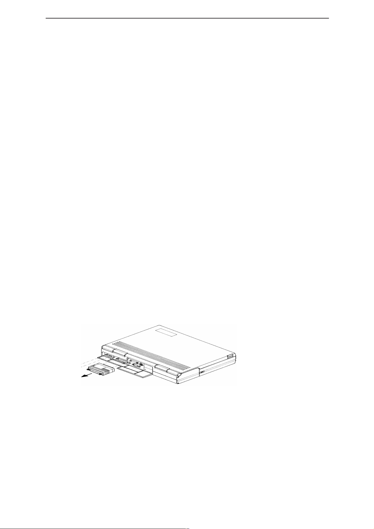
Attach the protection key PKD–1 (dongle) to parallel port one (25–pin
female D–connector) of the PC. When connecting the PKD–1 to the
parallel port be sure that you insert the PC end of the PKD–1 to the PC
(male side).
Figure 1. Dongle Insertion
The PKD–1 should not affect devices working with it. If some errors do
occur try printing without the PKD–1 connected. If printing is now OK
please contact your supplier who will endeavor to replace your PKD–1.
Page 6
Issue 1 04/99
Page 7
PAMS
WinTesla Users Guide
Technical Documentation
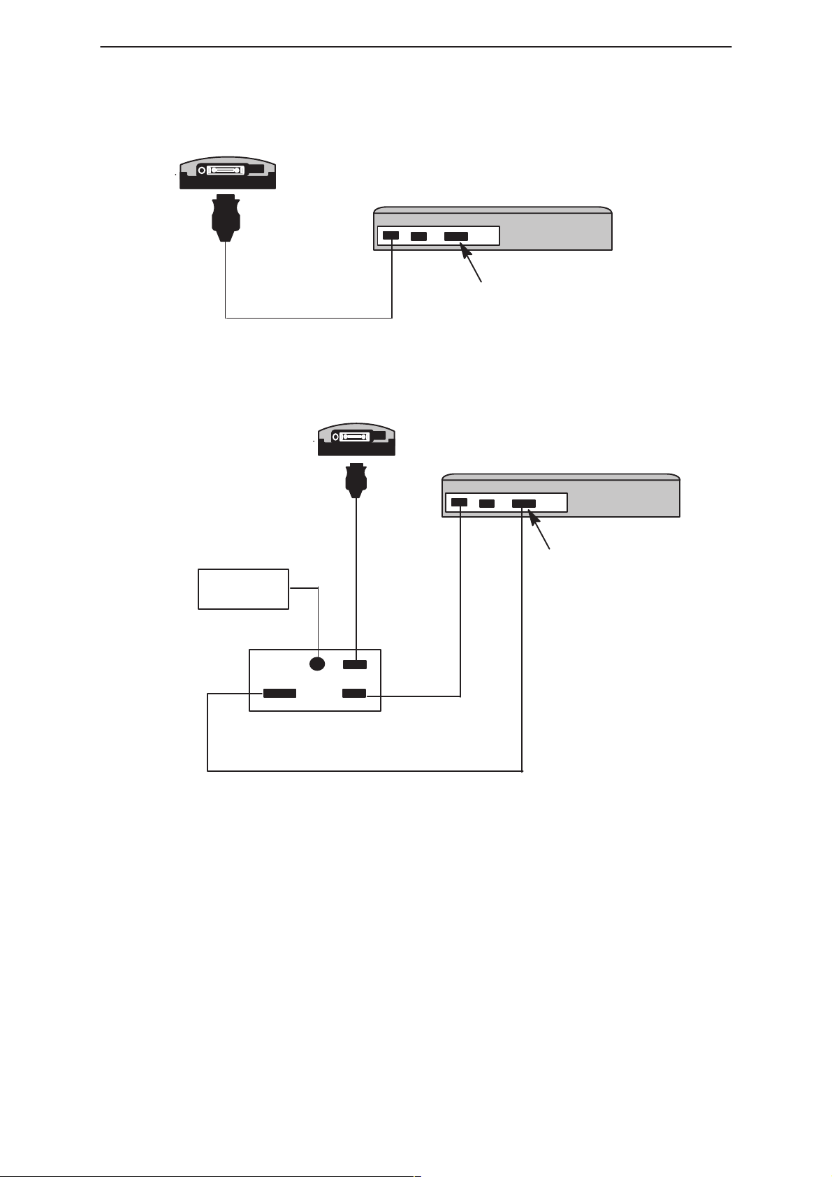
DAU–2
NHP–4
COM1 COM2 LPT–1
PC
PKD–1
Figure 2. Servicing setup
Power
Supply
Power
FPS–3C
Using Wintesla
Phone Independence
COM1 COM2 LPT–1
PC
DAU–2
PKD–1 (connect to dongle)
Phone
SerialParallel
Figure 3. Flash setup
The WinTesla application, “WinTesla.exe”, is phone independent. It relies
on separate, phone specific, “modules” to provide communication, menus
and test algorithms.
Issue 1 04/99
Page 7
Page 8
WinTesla Users Guide
PAMS
NHP–4
Technical Documentation
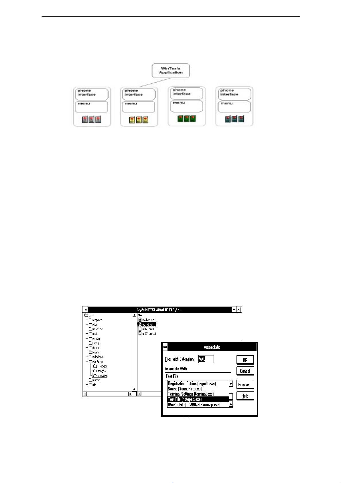
Figure 4. WinTesla with loaded interfaces
For each phone type – or product family – a phone interface module and
menu module are required. The modularity of WinTesla allows support
for other languages, so one phone type may have one phone interface
module and several menu modules, all in different languages.
WinTesla allows you to select the language you wish to use (if available),
and will automatically load the correct phone interface module for the
connected phone. When a different phone type is connected, WinTesla
will load the new phone interface and associated menus.
Login ID Setup
Once the software has been installed you need to set up your own Login
ID (max. 3 characters). Start Windows file manager and locate the
validate\op_id.val
Figure 5.
Double clicking on the ‘
message, in order to avoid this use the
manager and link the file to the Notepad application as shown below.
(located in the Wintesla subdir) file as shown in
Op_ID.val’
file (a text file) gives a windows error
File |Associate command in file
Page 8
Figure 5. Accessing Op_ID. val file
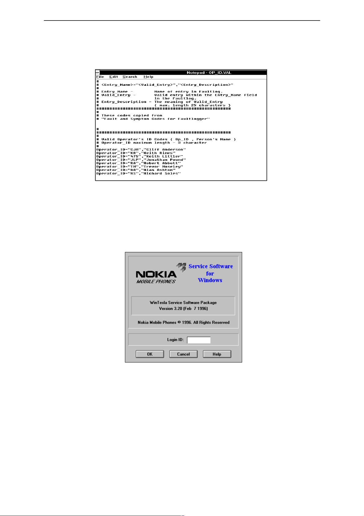
Now by double clicking on the ‘
Op_ID.val
’, Notepad opens and your own
Issue 1 04/99
Page 9
PAMS
WinTesla Users Guide
Technical Documentation
ID can be entered and saved accordingly. Enter or edit any operator
definitions following the existing format in this file.
Enter your id here
NHP–4
Figure 6. Editing Op_ID.val file
The Login Screen
When WinTesla first starts, the Login screen below will appear. Type in
your 3 character ID and press <Enter> or click on the ”OK” button.
If WinTesla can not find the file,
then the ”OK” button will be ‘greyed’.
Figure 7. Login Screen
op_id.val
, which contains the Login IDs,
If ”Cancel” is clicked then the Fault Logging feature of WinTesla will be
deactivated.
Issue 1 04/99
Page 9
Page 10
WinTesla Users Guide
PAMS
NHP–4
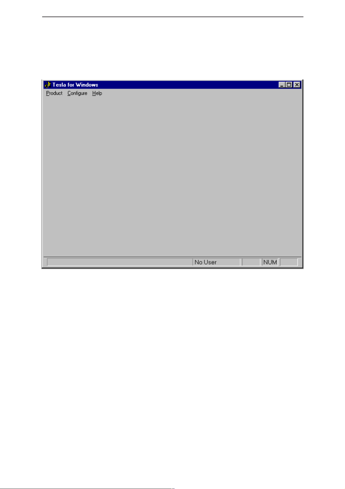
The WinTesla Screen
The main WinTesla screen – if no phone is attached – is displayed with 3
menu items at the top of the screen and a status bar at the bottom.
Technical Documentation
The information on the left of the status bar will be used to provide
information when WinTesla is performing tasks: such as reading data
from the phone. The status bar also includes the name of the current
user.
Page 10
Issue 1 04/99
Page 11
PAMS
WinTesla Users Guide
Technical Documentation
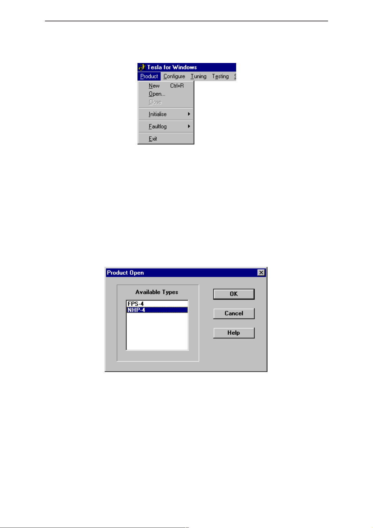
The Product Menu
New (Ctrl+R)
The ”New” function (which can also be activated by pressing <Ctrl+R>)
is used to scan for a phone when either the automatic rescan option is off
or the automatic rescan timer has not expired ( see
section for automatic rescan ).
NHP–4
Configure|Options
Open
If the phone type is unrecognized or unsupported by the current WinTesla
system then a warning message will be displayed.
The ”Open” function allows you to ”force load” a phone interface, even if
there is no phone connected to the system.
A dialog box will appear and list the supported phone types (see figure
above). To select a particular phone type to load; highlight the phone
type name and click on ”OK”.
Clicking on ”Cancel” will stop the request and no new phone type will
be loaded.
Loading a phone interface will disable the automatic rescan function (see
Configure|Options section for automatic rescan).
Close
This function will close the currently loaded phone type interface that had
been loaded using the
phone type interface if it was loaded by a rescan.
Issue 1 04/99
Product|Open function. You can not close a loaded
Page 11
Page 12
WinTesla Users Guide
PAMS
NHP–4
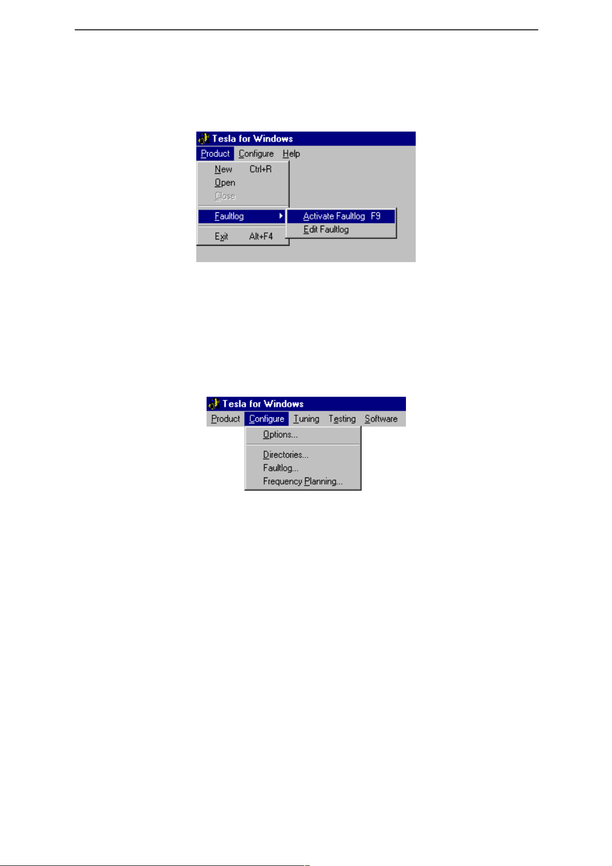
FaultLog
The FaultLog option has a sub–menu (below). These functions are
described in the ”FaultLog Application” section.
If the FaultLog function has been disabled – either because the Login ID
was not correct or disabled through the Configure|FaultLog function – then
these menus will be ”greyed” and made un–selectable.
Exit (Alt+F4)
Technical Documentation
Selecting this option will shut–down the WinTesla program.
The Configure Menu
The configuration menu allows you to setup such things as directory
paths, user interface language and FaultLog options.
Page 12
Issue 1 04/99
Page 13
PAMS
WinTesla Users Guide
Technical Documentation
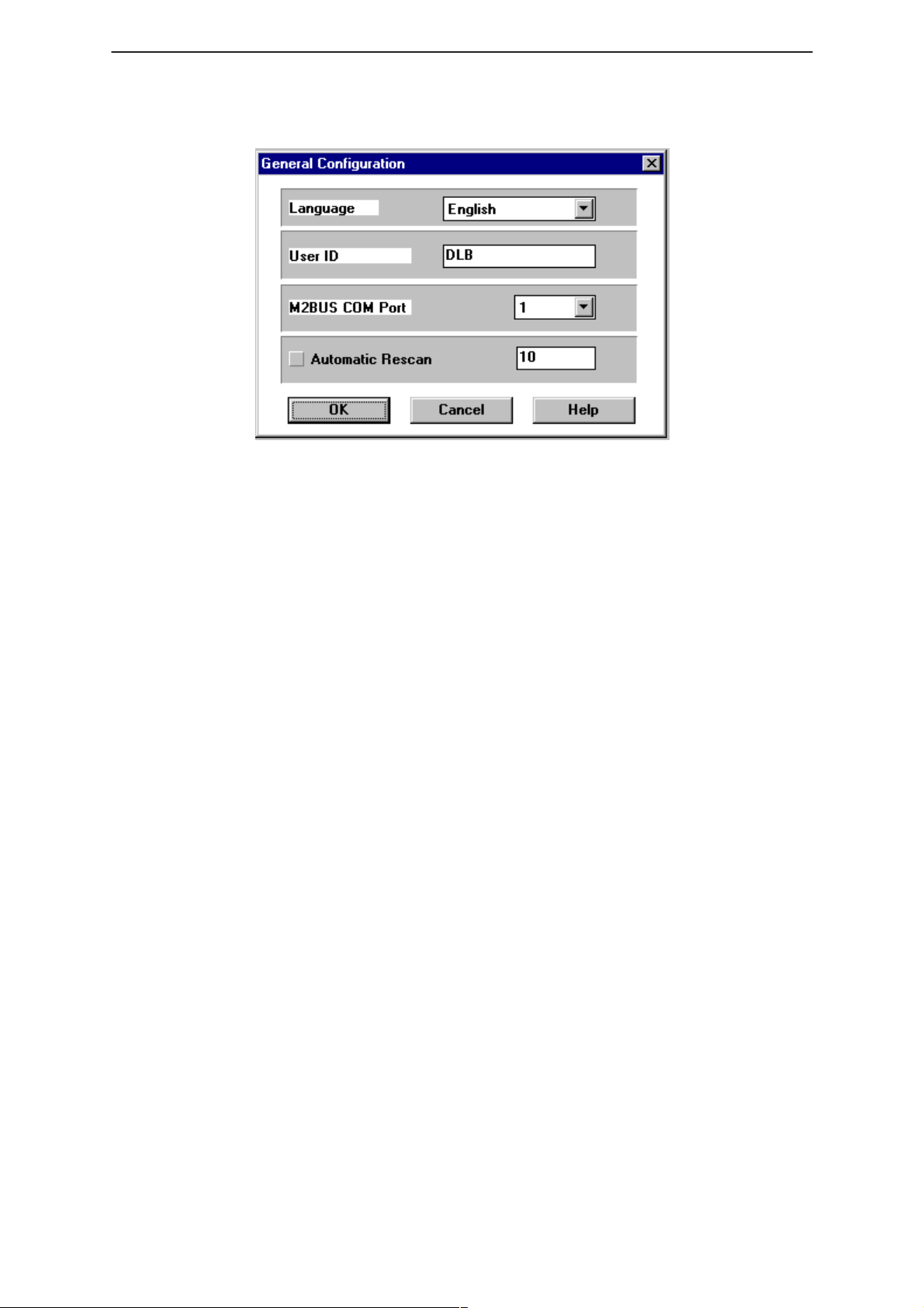
Options
Language
This option allows you to change the language used in the WinTesla
application.
NHP–4
Current Password / New Password / Retype Password
Currently not available
User ID
Allows the user ID to be entered if the users name is setup in the
opt_id.val (validation) file.
M2BUS COM Port
This option allows you to select which communications port the phone is
to be connected. The change will take place immediately after clicking
”OK”.
Automatic Rescan
Automatic rescan is a mechanism to automatically check for a new
phone; the time between rescans is user configurable. When a phone is
scanned and recognized, the corresponding phone interface and menu
are loaded, extending the main menu at the top of the screen and
displaying the phone type and description at the bottom of the screen.
Product|New (or Ctrl+R ) function can be used to rescan the phone
The
in–between automatic rescans or when automatic rescan has been
disabled. The automatic rescan mechanism is disabled when the
Product|Open function is used to load a phone interface.
A tick in the check–box indicates that the automatic rescan option has
been enabled. Clicking on the check–box (making the check–box blank)
will disable the automatic rescan option. The time between rescans (in
seconds) is entered into the edit box.
Clicking the ”OK” button will save any changes made. Clicking
”Cancel” will discard any changes you may have made.
Issue 1 04/99
Page 13
Page 14
WinTesla Users Guide
PAMS
NHP–4
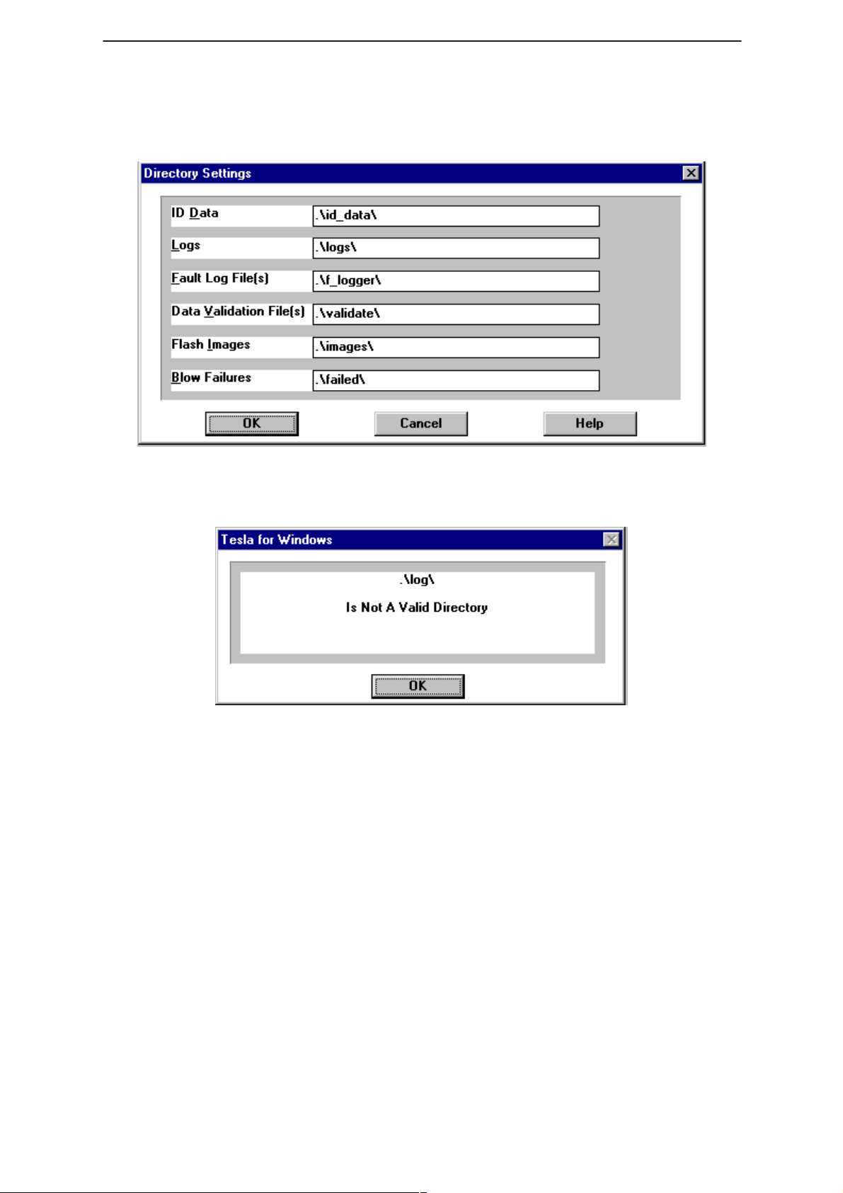
Directories
Technical Documentation
This function allows you to organize your data into different directories.
The directories must already exist. If an invalid directory is entered then
an error message will be displayed (below).
The use of a backslash (”\”) at the end of the directory name is optional.
Clicking on the ”OK” button will save your changes.
Page 14
Issue 1 04/99
Page 15
PAMS
WinTesla Users Guide
Technical Documentation
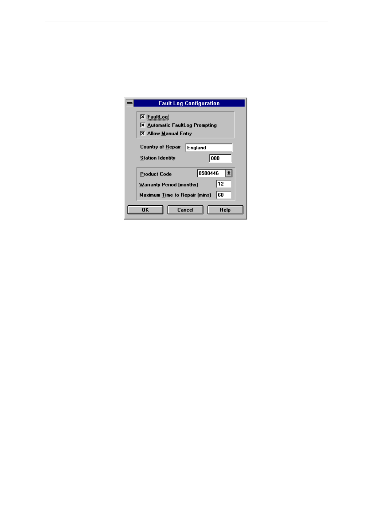
Fault Log Configuration
Fault Log is a feature that allows the PC to create a record of each phone
that is serviced for historical tracking. This function allows you to
configure the FaultLog mechanism. Clicking ”OK” after making
selections, saves all changes made.
NHP–4
Figure 8. FaultLog – configuration
Fault Log
This option allows you to enable or disable the FaultLog mechanism.
Choosing to disable the FaultLog mechanism results in the
|FaultLog options being ”greyed” and the F9 button being disabled.
Product
Allow Manual Entry
This option allows you to disable manual entry of data that was
unavailable from the phone.
Automatic Fault Log Prompting
Enabling this option results in a prompt being displayed if the phone has
changed.
Station Identity
Enter the unique identity of your ”workstation”; this ID is used to write
FaultLog files.
Country Of Repair
Enter the country of repair.
Warranty Period ( months )
Each product code has an associated warranty period. This option allows
you to change those warranty periods. If no phone is connected then all
product codes supported will be displayed. However, if a phone is
connected then only the product codes associated with that phone type
are displayed.
Note: Changing the Warranty Period in the Fault Log data file has no affect on the
products warranty terms as stated from the manufacturer.
Maximum Time To Repair ( minutes )
Enter the maximum time allowed to repair a phone.
Issue 1 04/99
Page 15
Page 16

WinTesla Users Guide
PAMS
NHP–4
Fault Log Application.
The aim of the Fault Log application is to provide NMP After Sales
Companies worldwide a standard method for the collection of Fault and
Repair Data from their service process’s. This information can also be
used by NMP R&D and Manufacturing organizations as well.
The Fault Log application can be regarded as a data entry sub–routine
run from the WinTesla Service Software package at the end of a repair.
This allows for quick and uniform recording of the service performed on
the product.
Each product repaired, will generate one unique record in a FaultLog file
consisting of up to 37 data fields containing information about the product
and how it was repaired. This information is read automatically where
possible, from the products own internal EEPROM and then entered
manually by the Service Technician to form a complete service record.
For more advanced implementations, the repair records are copied and
collected by the electronic mail system installed in the Service Center and
are sent electronically to a Central Service Database located in
Finland.Completing a FaultLog Record
Technical Documentation
Once WinTesla has been configured correctly it operates in the following
manner:–
Wintesla automatically reads the product details from the
products EEPROM and writes them as a record to a
pre–determined file.
Proceed with the repair task, utilising a combination of
software driven tuning and hardware modifications.
On completion of the repair task you have a choice:
A.)With the product still connected to the PC, manually display
the repair data entry screen by selecting Function Button F9.
Page 16
Issue 1 04/99
Page 17
PAMS
WinTesla Users Guide
Technical Documentation
B.) Alternatively, the product can be disconnected and the next
product for repair connected in its place.
So long as Automatic Prompting is enabled then the previous products
repair data entry screen will be displayed.
– Enter the repair work performed on the product in the repair
– Check the automatic data for this product, read earlier, to
– When satisfied with the data, save the entry. This process
The output file can then be manipulated by a number of different systems,
as required, as a detailed record of the product fault.
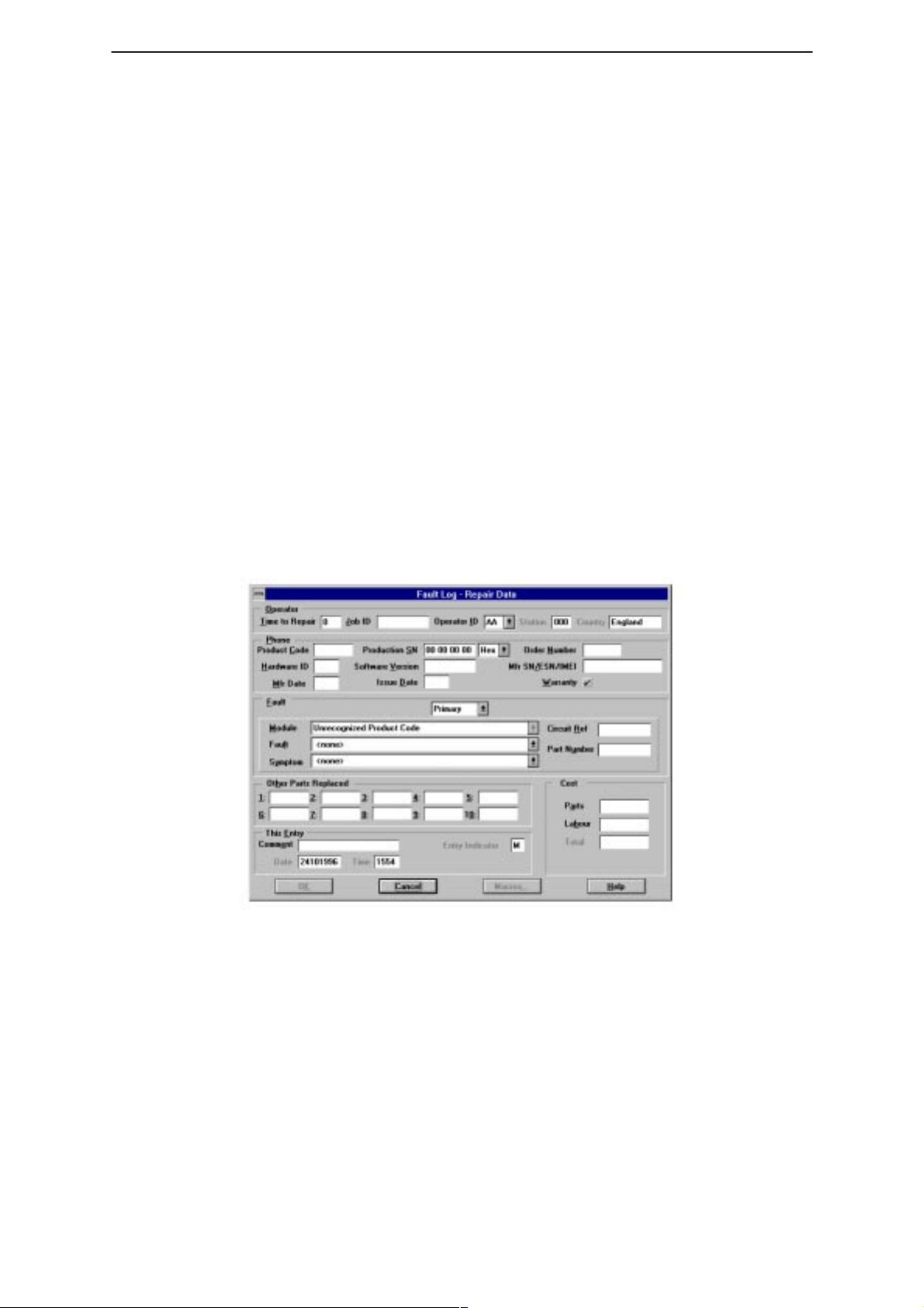
To attempt to record all of this information 37 data fields are defined for
each FaultLog record. These can be split as follows:–
– Product definition information fields
Most products have their information stored in EEPROM, WinTesla
automatically reads this information from the EEPROM and writes it to the
FaultLog record. This part of the record is shown below.
NHP–4
data screen.
ensure its accuracy.
adds a complete record containing the product details and
the repair details to the FaultLog output file.
Fields that are ”greyed out” etc. are data that has been automatically
retrieved from the phone’s EEPROM. All other fields are entered
manually; fields are summarized below.
Operator
Automatic: Station, Country
Manual :
Phone
Automatic: Product code, Production SN, Order No., Hardware
ID, Software version, Mfr. SN/ESN/IMEI, Mfr. Date,
Manual:
Issue 1 04/99
Time to repair, Job ID, Operator ID
Issue date
Warranty
Page 17
Page 18

WinTesla Users Guide
PAMS
NHP–4
Technical Documentation
Fault
Automatic: none
Manual
Module, Fault, Symptom, Circuit ref., Part Number
The current FaultLog application allows for the entering of three priority
levels of fault / repair information seen as
Tertiary
The
faults.
Module, Fault
and
Symptom
fields have variables selected by the
Primary, Secondary
and
arrows alongside each respective field.
A comprehensive list of faults and symptoms as well as all current
modules are already listed within the software. These three fields can be
updated by accessing and editing the following files in a similar manner
as described on page 8
Field DOS File
–
Modules
–
Faults, Symptoms
nhd4en.val–
faulten.val
Notepad – FAULTEN.VAL
Notepad – UI821EN.VAL
Page 18
Figure 9. Editing fault, symptoms, modules files
Issue 1 04/99
Page 19
PAMS
WinTesla Users Guide
Technical Documentation
Other Parts Replaced
Automatic none
Manual all fields
Enter other parts that have been replaced i.e. for wear and tear purposes
etc..
This Entry
Automatic ; Entry Indicator, Date, Time
Manual ;
Cost
Automatic ; Total
Manual ;
This facility is for the use of third party repairers only
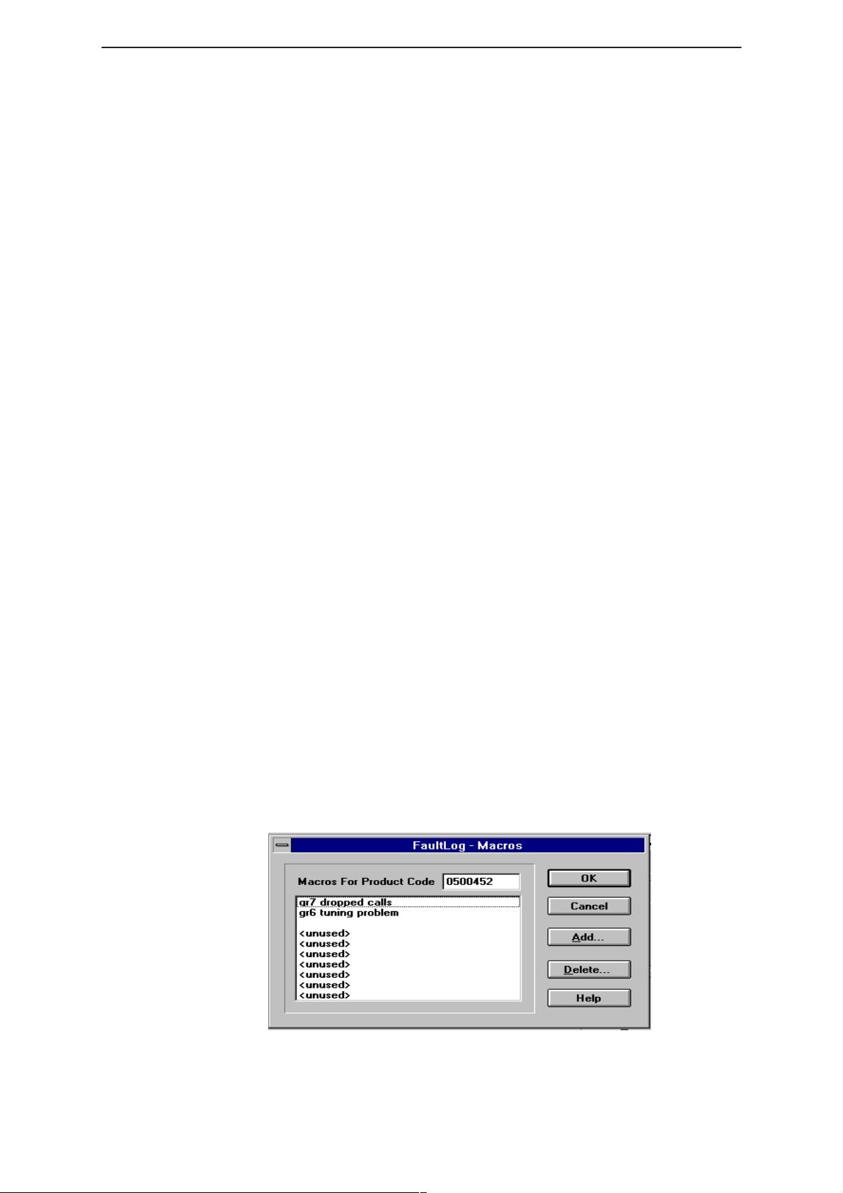
FaultLog Macros
The Macro sub–menu can be accessed by selecting the ”Macros”
button on the FaultLog main screen.
NHP–4
Comment
Parts, Labour
Macros in FaultLog are a set of standard repair actions defined and
stored in order to represent frequently repeated repairs. These Macro’s
are related to the Product Code of the product, so whatever product is
connected, FaultLog will display the Macro list for that particular Product
Code.
A Macro’s standard repair information can also be pasted into the
FaultLog record for that product.
Macro’s are saved initially under a name you can define yourself from the
main FaultLog screen. All the information contained in the manually
entered fields i.e. Module, Fault, Symptom, Circuit Ref and Part Number
is recorded and saved under this name.
Setting up a macro
After completing a manual entry as normal but before saving the
record, select the ”Macros” button. This will bring you into the
Macro definition screen.
Issue 1 04/99
Figure 10. FaultLog – macro setup
Page 19
Page 20

WinTesla Users Guide
PAMS
NHP–4
Technical Documentation
Place the cursor over the next available Macro entry then select
”Add”.
Give the Macro record a meaningful name and click on ”OK”. You
have now saved the repair data into a Macro for future use.
Use the ”Delete” function to remove unwanted macros.
Now, when a similar problem is seen with another unit you can recall this
saved repair information into the units FaultLog record. If needed, the
FaultLog record can be edited after being recalled to customize the repair
before saving the FaultLog record.
There are a maximum of 10 Macro’s definable for each Product Code. If
an eleventh is required, it will be necessary to overwrite one of the
previous Macro’s.
The Macro definition file is called
specified for the data validation files. If this path is a networked path all
operators connected to the network will be permitted to share a common
Macro list helping with reporting uniformity.
macro.fl
and will be found in the path
Help
An extensive help facility is available by clicking any screen or toolbar
help button and features convenient hypertext linking for easy navigation.
HD891 Module
Information in this section is specific to the HD891 module and assumes
that the setup procedures in the common interface section have been
carried out.
Installing the HD891 Service Module
The HD891 Service module software is delivered on a 3.5” diskette and
must be run under the Wintesla core software package.
To install the HD891 Service Module software, proceed as follows:
Insert the HD891 Service Module diskette into drive A: of your PC.
From Windows File Manager select the file a:\install.exe and click
”OK”.
Page 20
new
Follow the on screen instructions and select the
prompted to do so.
WARNING: The service module requires the Wintesla core software application to be
installed first for this module to function.
NOTE: Be sure to install the Service Module in the same directory as the Wintesla
core software application.
install option when
Issue 1 04/99
Page 21

PAMS
WinTesla Users Guide
Technical Documentation
Required Servicing Equipment
The following is a list of equipment that is needed in order to service the
HD891 family of products.
HD891 Software Service Module (product code: 0774062)
Dongle ‘blackbox’ adapter DBA–1 (product code: 0630044)
M2BUS adapter DAU–2 (product code: 0750006)
RS–232 adapter, 9–to–25 pins (product code: 4626170)
RS–232 cable (product code: 0730090)
Centronics cable (product code: 0730029)
Service cable SCS –1 (product code: 0770010)
Service cable SCS–10 (product code: 0775059)
Audio cable ADS–1 (product code: 0730011)
Modular cable XCM–1 (product code: 4626131)
Flash Programmer Set FPS–3C (product code: 0770110)
NHP–4
Power connector PCS–1 (product code: 0730012)
Modular T Connector cable (product code: 4626134)
Dummy Battery BTS–4 (product code: 0770009)
Covers off Jig JBS–16 (product code: 0775039)
Service box JBS–7 (product code: 0770015)
Issue 1 04/99
Page 21
Page 22

WinTesla Users Guide
PAMS
NHP–4
Equipment Setup
Caution: Make sure that you have switched off the PC and the printer before making
connections !
Caution: Do not connect the PKD–1 key to the serial port. Y ou may damage your
PKD–1 !
Attach the protection key PKD–1 to parallel port one (25–pin female
D–connector) of the PC. When connecting the PKD–1 to the parallel port
be sure that you insert the PC end of the PKD–1 to the PC (male side). If
you use a printer on parallel port one, place the PKD–1 between the PC
and your printer cable.
Next connect the M2BUS adapter to the serial port (RS–232) of the
computer. In case you are using a 9–pin serial port (normal with an AT
set) use the mating adapter supplied with the M2BUS adapter.
Attach one end of the XCM–1 modular cable to the DAU–2 PC/M2BUS
adapter and the other end to the JBS–7 service box. Use suitable
adapter, SCS–1 service cable when the covers of the phone are in place,
JBS–8 test frame with the phone covers off, and attach it to the phone.
Then connect it to the service box.
Technical Documentation
Page 22
Issue 1 04/99
Page 23
PAMS
WinTesla Users Guide
Technical Documentation
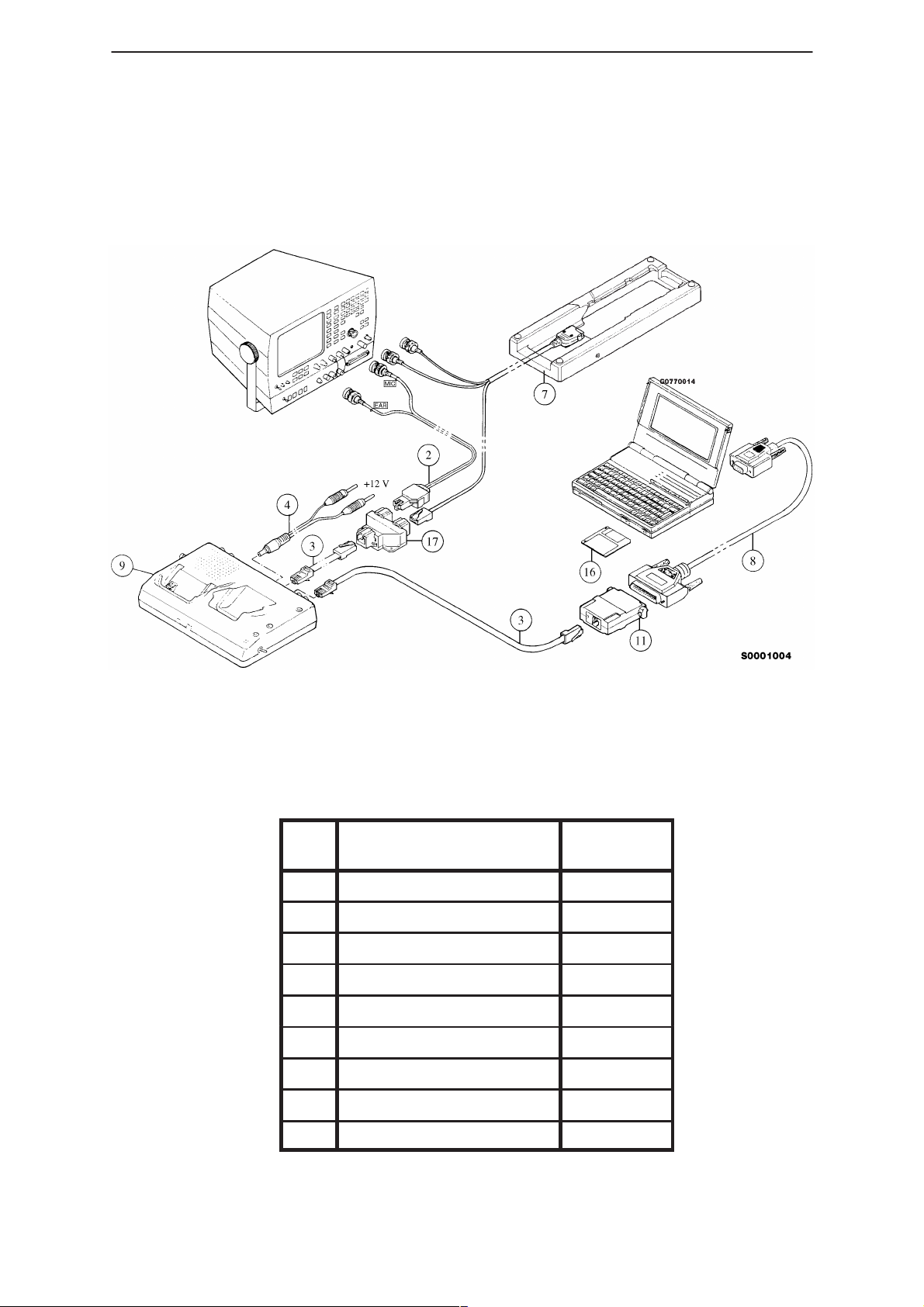
Dealer Setups
NHP–4
Figure 11. Testing/Tuning with covers off
Item Description Product
Code
2 ADS–1 0730011
3 XCM–1 4626170
4 PCS–1 0730012
7 JBS–16 0775039
8 RS232 Adapter 4626170
9 JBS–7 0770015
11 DAU–2 0750006
16 Software diskette 0774062
17 Modular T connector 4626134
Issue 1 04/99
Page 23
Page 24
WinTesla Users Guide
PAMS
NHP–4
Technical Documentation
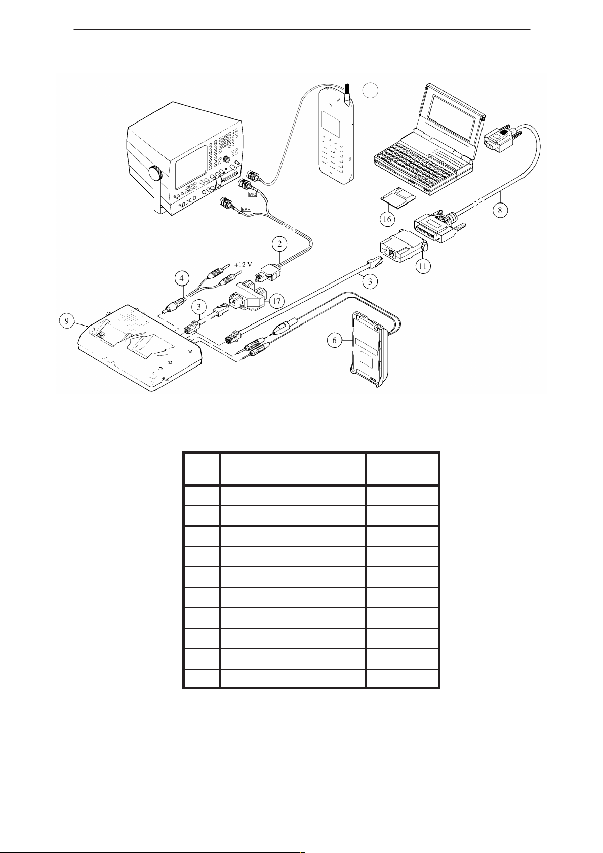
5
Figure 12. Testing/Tuning with covers on
Item Description Product
Code
2 ADS–1 0730011
3 XCM–1 4626170
4 PCS–1 0730012
5 TDA–1 0750086
6 BTS–4 0770009
8 RS232 Adapter 4626170
9 JBS–7 0770015
11 DAU–2 0750006
16 Software Diskette 0774062
17 Modular T connector 4626134
Page 24
Issue 1 04/99
Page 25

PAMS
WinTesla Users Guide
Technical Documentation
Main Menu
The main menu bar below appears when HD891 initializes, adding the
following new categories,
and
Product
Configure
Product
The following items are added to this menu when HD891 is recognized:
Initialise
Allows the phone to be set up in either
Normal Mode
When selecting
station and a displays this message. This is ”normal” operation mode of
the phone.
Norma
NHP–4
Tuning,Testing, Software, Dealer
have also changed.
Normal, Local or Minimum
l mode, the phone tries to synchronize to the base
and
Help.
mode.
Minimum Mode
When
MCU will communicate with the PC using the Service Software. This
mode is used for Flash software changes.
Local Mode
When
operation and set to a special mode allowing Tuning and Testing to be
done.
Minimum
Local
Configure
Frequency Planning
This configures the channel number, for a product type, to be
High
in order to allow losses to be configured for manual testing.
mode is selected, the phone is deactivated and only the
mode is selected, the phone is suspended from normal
Low, Mid,
Issue 1 04/99
Page 25
Page 26

WinTesla Users Guide
PAMS
NHP–4
Tuning Steps of Radio Unit
The Service software program places the phone in the Local mode,
during which the phone can be externally controlled via the M2BUS
interface.
The tuning values of the phone reside in the EEPROM. Before tuning
these values are read by the Service software and the user can change
these values with tuning functions.
During tuning, keep the following in mind:
– Take care not to damage sensitive measuring instruments with
excessive RF power.
– Carry out all tuning steps in the shortest possible time to avoid
excessive heating of RF units.
– Perform all tuning steps in the order presented.
– Limit the power supply to a maximum current of 1.3 amps to prevent
excessive damage to the phone in the event of shorted components.
Technical Documentation
– Never try to mask a fault by ”tuning it out.”
Accuracy of the Equipment During Measurement
– Power supply 1; nominal voltage 12 ±0.5 V current cap. min. 1.5 A for
service box (JBS–7).
– Power supply 2 ;nominal voltage 6.0 ±0.1 V, current cap. min. 1.5 A.
– Modulation analyzer power level resolution 0.1 dB, accuracy ±0.5 dB.
Frequency counter accuracy 0.1 ppm 〈±80 Hz).
– RF generator; frequency res. 10 Hz amplitude res. 0.1 dB frequency
stab. ±0.25 ppm.
– Spectrum analyzer; dynamic range 70 dB, accuracy ±1 dB (For power
level measurement accuracy ±0.5 dB).
Baseband Alignment and Flash Station Tests
Flash Programming
This procedure programs the phone software into the flash memory.
Page 26
Flash Programming procedure:
– Connect the phone to the FPS–3C Flash Programming Box.
– Select ”Software –> Flash”.
– Select the flash file for the desired software version.
– Click ”OK”.
– Check the following boxes: ”Set the Phone to Minimum Mode”
and ”Initialize EEPROM after Flash”.
Issue 1 04/99
Page 27

PAMS
WinTesla Users Guide
Technical Documentation
– If the phone had been successfully aligned before and the RF tuning
parameters are to be retained, check the ”Keep RF Parameters”
box.
– If the user data (i.e., phone number, service settings, etc.) are to be
retained, check the ”Keep User Data” box.
– If the selected software had been previously downloaded to the flash
box, click the ”Skip Download to Flash Box” box. This feature
is particularly useful when doing multiple flash downloads with the
same software.
– Click on ”OK” to download the new software.
Flash Download Verification procedure:
– From the main menu of the Service Software, select ”View –>
Phone Identity”.
– If the window that pops up displays the software version that had been
selected for download, then the phone was successfully flashed.
Factory Value Set
NHP–4
This procedure initializes the EEPROM with default values.
Factory Value Set procedure:
– Using the JBS–7 service jig, replace the standard battery of the phone
with the dummy battery BTS–4.
– Apply +6.0 V to dummy battery.
– Select ”Software –> Initialize EEPROM”.
– Select the phone type that the phone is to be set as, i.e., Sprint or
Nokia.
– Click on the box(es) for the EEPROM parameters that are to be
initialized.
– Note that there is a ”View RF Param” button. This feature enables
the user to view the RF tuning parameters stored in the EEPROM.
The user may wish to use this feature to verify that the stored RF
parameters are no longer needed as initializing the EEPROM will
erase all previous values.
– Click ”OK” to initialize the EEPROM.
Battery Voltage Tuning
This procedure reads the analog–to–digital conversion value of the
BATT_ADC voltage when set to +6.0 V for a reference parameter. The
readings are performed ten times and an average result is calculated
which is then stored into the EEPROM.
Battery Voltage Tuning procedure:
– Using the JBS–7 service jig, replace the standard battery of the phone
Issue 1 04/99
with the dummy battery BTS–4.
Page 27
Page 28

WinTesla Users Guide
PAMS
NHP–4
– Apply +6.0 V to dummy battery.
– Select ”Tuning –> Battery Voltage”.
– Store the new values to the phone by clicking on ”Tune”.
Charger Voltage Tuning
Similar to Battery Voltage Tuning, this procedure reads the
analog–to–digital conversion value of the CHAR_ADC voltage when set
to +6.0 V for a reference parameter. The readings are performed ten
times and an average result is calculated which is then stored into the
EEPROM.
Charger Voltage Tuning procedure:
– Using the JBS–7 service jig, replace the standard battery of the phone
with the dummy battery BTS–4.
– Apply +6.0 V to dummy battery.
– Select ”Tuning –> Battery Voltage”.
Technical Documentation
– Store the new values to the phone by clicking on ”Tune”.
RF Temperature Tuning
This procedure reads the analog–to–digital conversion value of the
ambient temperature and stores it as two values, RFTEMP1 and
RFTEMP2, as a temperature reference for the phone. This adjustment
should be made with the phone at room temperature, +25C. It is
important that all RF transmitter tunings be done as quickly as possible.
This is to ensure that this reference temperature adjustment is within
limits required for temperature compensation.
RF Temperature tuning:
– Using the JBS–7 service jig, replace the standard battery of the phone
with the dummy battery BTS–4.
– Apply +6.0 V to dummy battery.
– Select ”Tuning –> RF Temp”.
– The Program reads the ADC values of the ambient temperature for
the EEPROM parameters, RFTEMP1 and RFTEMP2.
– Store the new values to the phone by clicking on ”Tune”.
Page 28
Issue 1 04/99
Page 29

PAMS
WinTesla Users Guide
Technical Documentation
RF Tuning and Testing
WARNING: The phone can not be Tuned properly if connected to the FPS–3C Flash
Programming Box. Please use only one of the setup configurations listed in the “Dealer
Setups” section of the NHD–4NX Service Manual.
CDMA Bias Quiescent Current Test
CAUTION: During procedures that require the phone to transmit high power, ensure that
the power supply limits the current to a maximim of 1.3 amps. This is to prevent further
damage to the phone in the event there are any shorted components within the transmit
circuitry.
This test checks if there is excessive current drain while transmitting.
This procedure reads the current consumption of the phone while
transmitting with minimum gain.
CDMA Bias Quiescent Current test procedure:
– Using the JBS–7 service jig, replace the standard battery of the phone
with the dummy battery BTS–4.
– Apply +6.0 V to dummy battery.
NHP–4
– Connect a spectrum analyzer to the antenna connector.
– Select ”Testing –> CDMA Tests”.
– Check the ”Troubleshooting Mode On” box and allow the phone
– Check the ”Rho On” box to turn on the transmitter.
– Select ”CDMA TX Gain Control”.
– A warning message window will appear reminding the user to limit the
– A TX Gain Control slider with a range from 0 to 1023 will appear. The
– Check that the phone current is within specified limits.
– Click on ”Close” when done.
AFC Tuning
This procedure tunes the VCTCXO frequency to 15.36 MHz. An
unmodulated transmitter carrier on channel 650 is used to perform this
test. The VCTCXO is tuned by adjusting the AFC PDM until the carrier is
on frequency at 1882.50 MHz within +/–100 Hz and then storing the PDM
value into the EEPROM.
to enter Suspend CDMA mode.
power supply to 1.3 amps. Click ”OK” to continue.
slider represents the TX IF AGC DAC value with the value of 0 being
maximum gain and 1023 being minimum gain. Set the TX Gain
Control to minimum gain.
AFC Tuning procedure:
– Using the JBS–7 service jig, replace the standard battery of the phone
– Apply +6.0 V to dummy battery.
– Connect a spectrum analyzer to the antenna connector.
Issue 1 04/99
with the dummy battery BTS–4.
Page 29
Page 30

WinTesla Users Guide
PAMS
NHP–4
– Select ”Tuning –> AFC”.
– Follow the set–up instructions displayed and click on ”Continue”.
– Adjust the carrier frequency to 1882.50 MHz +/– 100 Hz with the
PgUp/PgDn keys for coase adjustments and the Up/Dn arrow keys for
fine adjustments.
– Click on ”Save & Exit” to store the PDM value to the EEPROM.
RX AGC Tuning and Dynamic Range Check
This procedure aligns the RX AGC circuitry. The RX AGC is aligned by
injecting a carrier signal at an offset of 540 kHz from the assigned
channel frequency (i.e., Ch 650 = 1962.5 MHz, injected signal = 1963.04
MHz.) The gain of the RX AGC circuitry (IF AGC IC, N9) is then adjusted
to obtain a fixed output level for the receiver I and Q output signals. The
amount of adjustment to obtain this fixed level corresponds to the RX
CTR value. By using the RX CTR value, an AGC tuning value is then
derived. The entire procedure is performed ten times corresponding to
ten different power levels of the injected carrier signal, ranging from –105
dBm to –25 dBm.
Technical Documentation
RX AGC Tuning and Dynamic Range Check procedure:
– Using the JBS–7 service jig, replace the standard battery of the phone
with the dummy battery BTS–4.
– Apply +6.0 V to dummy battery.
– Connect a signal generator to the antenna connector.
– Select ”Tuning –> RX AGC/Dynamic Range”.
– Follow the set–up instructions displayed.
– Click on ”Next” to read the AGC tuning value for the first RX signal
level.
– Repeat the procedures and continue until all ten power levels have
been measured.
– Click on ”Save & Exit” to store the AGC tuning values to the
EEPROM.
Page 30
Issue 1 04/99
Page 31

PAMS
WinTesla Users Guide
Technical Documentation
TX Gain Check
CAUTION: During procedures that require the phone to transmit high power, ensure that
the power supply limits the current to a maximim of 1.3 amps. This is to prevent further
damage to the phone in the event there are any shorted components within the transmit
circuitry.
This test checks the dynamic range of the TX attenuator to ensure that
there is enough gain in the TX chain. During normal operation the TX RF
ATT (N300) control signal is fixed and not adjusted. However, during this
procedure the phone will transmit with maximum gain from the TX IF AGC
IC (N308) and with maximum attenuation from the TX RF ATT (N300) at
channel 1175 to duplicate a worst case scenario for TX power output.
TX Gain Check procedure:
– Using the JBS–7 service jig, replace the standard battery of the phone
with the dummy battery BTS–4.
– Apply +6.0 V to dummy battery.
– Connect a spectrum analyzer, power meter, or CDMA Test Box to the
antenna connector.
NHP–4
– Select ”Tuning –> TX Gain Check”.
– Follow the set–up instructions displayed.
– Enter the measured power into the TX Power window.
– Click on ”Exit”.
TX IF AGC Tuning and Dynamic Range Check
CAUTION: During procedures that require the phone to transmit high power, ensure that
the power supply limits the current to a maximim of 1.3 amps. This is to prevent further
damage to the phone in the event there are any shorted components within the transmit
circuitry.
Since the gain of the TX PA (N304) and the amount of attenuation at TX
RF ATT (N300) are fixed, only the TX AGC circuitry needs to be
calibrated. For every TX CTR value used, a certain amount of TX gain is
expected form the TX AGC circuitry. This procedure transmits the phone
according to a predetermined TX CTR value and compares the measured
result to a typical expected value. The difference is then used to
calculate the tuning value. The procedure is done seventeen times for
different TX CTR values that correspond to a transmit range of from
approximately –69 dBm to +28 dBm to ensure linearity across the
dynamic range of the TX AGC circuitry.
TX AGC Tuning and Dynamic Range Check procedure:
– Using the JBS–7 service jig, replace the standard battery of the phone
– Apply +6.0 V to dummy battery.
– Connect a spectrum analyzer, power meter, or CDMA Test Box to the
Issue 1 04/99
with the dummy battery BTS–4.
antenna connector.
Page 31
Page 32

WinTesla Users Guide
PAMS
NHP–4
Technical Documentation
– Select ”Tuning –> TX IF AGC Tuning/Dynamic Range Check”.
– A warning message window will appear reminding the user to limit the
power supply to 1.3 amps. Click ”OK” to continue.
– Follow the set–up instructions displayed.
– Measure the transmit power for the first TX Counter value and enter it
in the corresponding window.
– Click on ”Next” to continue to the next TX Counter value.
– Repeat the measurement steps and continue until the transmit power
for all TX Counter values have been measured and entered.
– Click on ”Save & Exit” to store the tuning values to the EEPROM.
TX Limiting, TX Emissions, and Frequency Compensation
CAUTION: During procedures that require the phone to transmit power, ensure that the
power supply limits the current to a maximim of 1.3 amps. This is to prevent further
damage to the phone in the event there are any shorted components within the transmit
circuitry.
This procedure sets the limit for maximum TX output power. The TX limit
is set to ensure that the phone does not transmit excessive power which
may interfere with the CDMA network. Also, the TX limit ensures that the
phone meets SAR requirements and prevents excessive current
consumption thereby prolonging battery life. During this procedure the
TX limiting PDM (TXI REFC) is adjusted while the phone is transmitting to
obtain an output level of approximately 22.8 dBm. The current is also
measured to check that it is within specified limits.
After the TX limiting PDM value is determined, a TX emissions test is
done by measuring the difference (dBc) between the carrier and the ACP
(adjacent channel power), +/–1.265 MHz offset from the carrier.
Finally, the phone transmits on five other channels using the TX limiting
value just obtained. At each channel the output power is measured and
an algorithm determines the frequency compensation PDM values for a
flat frequency response across the TX bandwidth for TX limiting.
TX Limiting, TX Emissions, and Frequency Compensation procedure:
– Using the JBS–7 service jig, replace the standard battery of the phone
with the dummy battery BTS–4.
– Apply +6.0 V to dummy battery.
– Connect a spectrum analyzer and/or a CDMA Test Box (with a built–in
spectrum analyzer if used alone) to the antenna connector.
– Select ”Tuning –> TX Limiting Level”.
– Follow the set–up instructions displayed.
– Adjust the TX limit until approximately 22.8 dBm is obtained by using
the PgUp/PgDn keys for coarse adjustments and the Up/Dn arrow
keys for fine adjustments.
– Enter the measured TX power in the TX Output window.
– Enter the measured current consumption in the Phone current window.
Page 32
Issue 1 04/99
Page 33

PAMS
WinTesla Users Guide
Technical Documentation
– Click on ”Next” and follow the set–up instructions for TX Emissions
measurement.
– Measure the dBc of the ACP. Enter the absolute value of the dBc in
the TX Emissions window (i.e., enter 32 if the measure value was
–32dBc).
– Then enter the measured TX power in the window corresponding to
the first channel (1851.25 MHZ).
– Click on ”Next” and enter the measured transmit power for the next
frequency.
– Repeat the above step and continue until all other frequencies have
been measured.
– Click on ”Save & Exit” to store the TX limiting PDM and frequency
compensation values into the EEPROM.
Open–Loop AGC Alignment
This procedure ensures that the phone satisfies the CDMA system
requirement for open loop gain. The requirement is such that the power
level of the forward link plus the reverse link power must equal to –76
dBm. In other words, RX power + TX power = –76 dBm.
NHP–4
For example: If RX signal level = –90 dBm
Then TX signal level = +14 dBm
–90 dBm + 14 dBm = –76 dBm
A parameter called CLoopRef is used to offset the received signal so that
the TX output power level meets the open loop gain requirement. During
this procedure a RX signal at – 65 dBm is injected into phone and the
phone’s transmitted power is measured to determine the CLoopRef value.
This process is performed over seven different channels to ensure a flat
frequency response.
CLoopRef Alignment procedure:
– Using the JBS–7 service jig, replace the standard battery of the phone
with the dummy battery BTS–4.
– Apply +6.0 V to dummy battery.
– Connect a signal generator and a spectrum analyzer/power meter or a
CDMA Test Box to the antenna connector.
– Select ”Tuning –> Open–Loop AGC”.
– Follow the set–up instructions displayed.
– Measure the TX power for the first channel and enter it in the TX
– Click on ”Next” to measure the next channel.
– Repeat the measurement step above and continue until all channels
– Click on ”Save & Exit” to store the CLoopRef value to the
Issue 1 04/99
power window.
have been measured.
EEPROM.
Page 33
Page 34
WinTesla Users Guide
PAMS
NHP–4
Testing
Self Tests
This option runs the phone’s self test sequences and reports any
processor visible faults. The self tests provide an effective initial test for a
faulty phone.
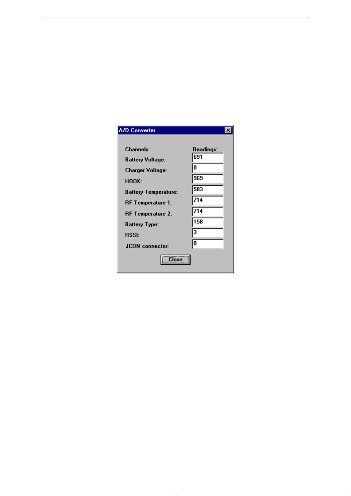
ADC Readings
Technical Documentation
This option allows the phone’s ADC readings to be displayed. The
readings are updated every few seconds. There may be some delay
before the mouse or keyboard responds while running this test.
Page 34
Issue 1 04/99
Page 35
PAMS
WinTesla Users Guide
Technical Documentation
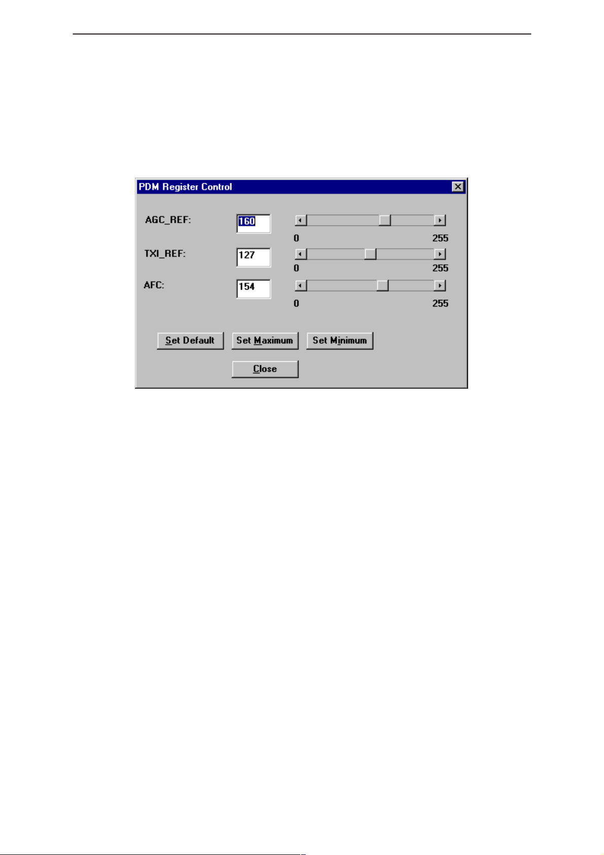
Pulse Division Modulator (PDM) Control
This test screen is to allow control of each PDM separately. The tests in
this section will use the PDM controls from this screen during their
execution.
PDM Register Control
NHP–4
KEYS:
– <Set Default> – Sets all PDMs to there default values.
– <Set Maximum> – Sets all PDMs to there Maximum values.
– <Set Minimum> – Sets all PDMs to there Minimum values.
Issue 1 04/99
Page 35
Page 36
WinTesla Users Guide
PAMS
NHP–4
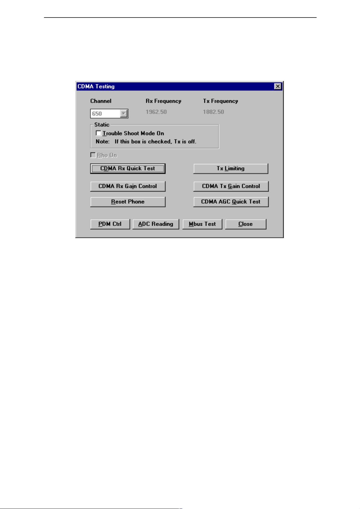
CDMA Testing
This screen is used when testing and troubleshooting the phone in CDMA
mode. Below is an example screen.
Technical Documentation
Keys:
PDM Ctrl – Opens the PDM Control Screen.
ADC Reading – Opens the ADC reading screen.
Quick RX Test – Opens the Quick Receiver test screen.
Mbus Test – Tests the communication between the phone and the
computer.
Close – Exits the current screen.
RHO on:
RHO on – turns the CDMA transmitter on/off.
Troubleshooting mode on:
Troubleshooting Mode on – will set the phone into CDMA mode for
technical troubleshooting. This mode is the Local mode for CDMA.
CDMA RX Quick Test
This function provides a simple, yet effective method of verifying the
receiver operation. This test sets the phone to channel 650. The user is
then directed to input an RX signal at –65 dBm into the phone and
measure the RX counter value. The test then guides the user to vary the
RX input signal to –85 dBm and –105 dBm and measure the respective
RX counter values. By observing the difference in measured RX counter
values vs the input signals, the functionality of the receiver can be
observed.
Page 36
Issue 1 04/99
Page 37

PAMS
WinTesla Users Guide
Technical Documentation
CDMA RX Gain Control
This function enables the user to manually control the amount of gain in
the receiver. Upon selecting this function, the user is presented with a
slider control with a range from 0 to 1023. The value of the slider
represents the RX DAC value used to control the gain of the RX IF AGC
IC (N9) with the value of 0 being maximum gain and 1023 being minimum
gain.
Reset Phone
This function simply resets the phone to normal operating mode.
TX Limiting
This function allows the user to manually control the TX limiting PDM (TXI
REFC) resulting in changing the set point of the TX limit for the phone.
By controlling the PDM, the user can test the TX lImiting operation and
the related TX circuitry. This function also enables the user to test the
frequency compensation performance of the phone by presenting a
frequency sweep from channel 25 to 1175 at the TX limit. The user
selects the step gain of the frequency sweep, i.e., step up every 50
channels, and the amount of time (in miliseconds) the phone will transmit
at each channel.
NHP–4
CDMA TX Gain Control
This function enables the user to manually control the amount of gain in
the transmitter. Upon selecting this function, the user is presented with a
slider control with a range from 0 to 1023. The value of the slider
represents the TX DAC value used to control the gain of the TX IF AGC
IC (N308) with the value of 0 being maximum gain and 1023 being
minimum gain.
CDMA AGC Quick Test
This function allows the user to test both the RX and TX AGC
performance of the phone. The test sets the phone to channel 650 and
the phone transmits it output power in accordance with the receive signal
strength. The user is first directed to input an RX signal at –65 dBm
where the test records the RX and TX counter values for that signal level.
The user is then directed to change the RX siganl level to –85 dBm which
should change the RX and TX counter values accordanly. By measuring
the difference between the counter values for each receive signal level,
the user can quickly determine if the AGC circuitries are functional.
Issue 1 04/99
Page 37
Page 38
WinTesla Users Guide
PAMS
NHP–4
Software Menu
The Software menu provides the following options:
Flashing
Technical Documentation
This option allows you Reflash a phone with a new version of flash
software, enabling new features to be added and bugs to be removed.
This Reflash option relies on the phone being in full working order and
containing the correct HWID and Product Code.
NOTE: To successfully update the flash code, the Nokia FPS–3C MUST be
WARNING:The computer that is connected to the FPS–3C Flash box MUST have it’s
Reflashing summary:
– Ensure the computers parallel port is configured properly.
– Select ”Software –> Flash”.
– Select the correct flash file to be flashed to the phone.
– Set Flash options in dialog box.
– Click on the ”Flash” button.
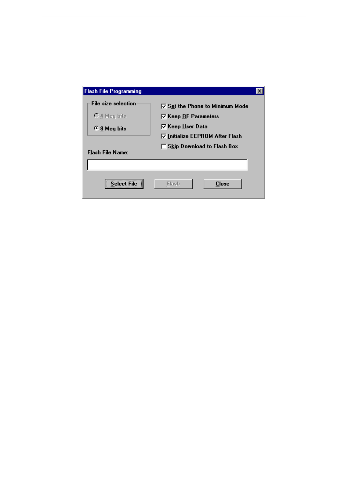
Dialog Options
Each of the options available are described below. It is suggested that
only experienced operators change these settings from there default
values.
connected to the PC that is running the WinTesla software. (see mechanical
connections in the service manual for details)
parallel port configuration set to standard AT type. Otherwise downloading
the flash image to the “black box” will fail.
Page 38
File size selection
Changes the size parameters for the flash file. Default value is 8 Meg bits.
Check box – set phone to minimum mode
Automatically sets the phone to minimum mode. If not set, the operator
must “force” the phone to this mode using hardware.
Issue 1 04/99
Page 39

PAMS
WinTesla Users Guide
Technical Documentation
Check box – Keep RF parameters
This option will save the RF parameters before flashing the phone. Once
flash updating is complete, these parameters will be stored back to the
phone.
Check box – Keep User Data
This option will save user data before flashing the phone. Once flash
updating is complete, the user data will be saved back into the phone.
USER DATA SAVED:
– Short Code Memory
– NAM programming information
– Calling Card Numbers
– SID Lists
– System Feature codes
– UI Settings
NHP–4
– Warranty Information
Check box – Initialize EEPROM after Flash
This option will prompt for initialization of the EEPROM after flash
updating is complete. It is recommended that the EEPROM be
“Initialized“ after flash updating the phone. (
more details on this function
Check box – Skip download to Flash box
The flash update is done using a two step process. the flash image is
downloaded to the flash box in the first step. This takes about 30 to 45
seconds. Then the image is updated on the phone during the second
step.
This option is useful if you are updating several phones with the same
flash image. After completing the first phone update, checking this option
will skip the first step of downloading the flash image to the box again. It
is not necessary to download the image again because the box will
contain the last image loaded unless a loss of power occurs.
)
see Initialize EEPROM for
Issue 1 04/99
Page 39
Page 40
WinTesla Users Guide
PAMS
NHP–4
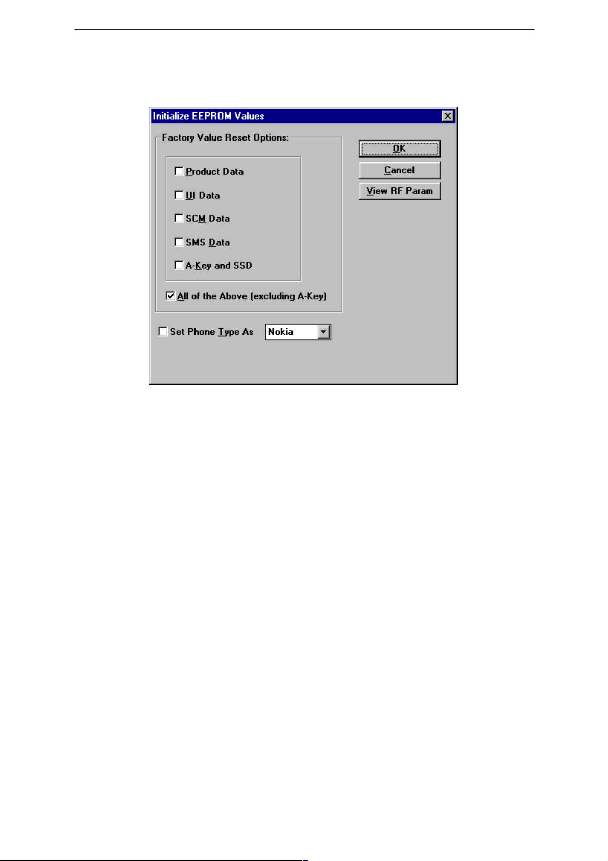
Initialize EEPROM
Technical Documentation
This option will re–initialize the phone’s EEPROM settings.
CAUTION: All the phone’s calibrated (tuned) data will be erased by this option and the
phone MUST now be recalibrated.
Product Data
This option will reset the Product data.
UI Data
This option will reset the user interface data.
SCM Data
This option will reset the short code memory data.
SMS Data
This option will reset the short messaging services data.
All of the above
This option will reset all of the above.
View RF Parameters
Opens the RF parameters dialog for viewing this data.
Page 40
Issue 1 04/99
Page 41

PAMS
WinTesla Users Guide
Technical Documentation
Dealer Menu
NAM Programming
NHP–4
This option allows you to program the NAM information, wake up
message, Emergency numbers, Lock code and security code of the
phone.
Keys:
NAM Selection
Selects NAM contents to be displayed.
Load File
Prompts user to select a file containing NAM information.
Save File
Allows user to save screen contents to a file.
Read Phone
Reads phone contents to screen.
Write Phone
Writes contents of screen to phone.
Issue 1 04/99
Page 41
Page 42

WinTesla Users Guide
PAMS
NHP–4
Technical Documentation
Default NAM Parameter Settings
These settings apply to both NAM 1 and NAM 2 unless stated otherwise. Values are shown in
decimal format.
Parameter Default Setting Valid Values
Own Number (Phone No. associated
with NAM, more specifically known as
the MIN)
Home SID List 1 – 32767 for each SID.
Access Overload Class last number of MIN 0 – 15
NAM Status Enabled/Disabled
Group ID 10 0 – 15
Access Method 1 0,1
Local Use Mark 1 0,1
Country Code 0 0 – 999
Network Code 0 0 – 99
000 000 XXXX (where XXXX
is the last 4 digits of ESN)
10 digits;
Up to 4 unique SIDs
Directory Number (Phone No. associated with NAM, more specifically known
as the MDN)
Emergency Numbers 911, *911, empty.
Lock Code 1234
Security Code 12345
000 000 XXXX (where XXXX
is the last 4 digits of ESN)
10 digits;
Page 42
Issue 1 04/99
Page 43

PAMS
WinTesla Users Guide
Technical Documentation
Short Code Memory (SCM)
NHP–4
This option allows the user to change the phone directory numbers (also
known as short code memory).
Keys:
Close
Closes Short Code memory screen.
Load File
Prompts user to select a file containing Short Code Memory information.
Save File
Allows user to save screen contents to a file.
Read Phone
Reads phone contents to screen.
Write Phone
Writes contents of screen to phone.
Edit
Edits the highlighted entry.
Delete
Deletes the highlighted entry.
Issue 1 04/99
Page 43
Page 44

WinTesla Users Guide
PAMS
NHP–4
SID Programming
This option allows you to edit the SID list. Highlight an entry using the
<TAB> key and press enter to edit.
Technical Documentation
Keys:
Load File
Prompts user to select a file containing SID information.
Save File
Allows user to save screen contents to a file.
Read Phone
Reads phone contents to screen.
Write Phone
Writes contents of screen to phone.
Page 44
Issue 1 04/99
Page 45

PAMS
WinTesla Users Guide
Technical Documentation
Calling Cards
NHP–4
This option allows the user to program the calling card information into
the phone.
Card Name
Allows user to change the name of the calling card display in the phones
menu.
Access Method
Allows user to select the appropriate method for connecting with the
service providers network according to the calling card requirements.
Please contact your service provider for details or the calling card
instructions. Changing this setting causes the phone to execute the
sequence of events according to option choosen.
– Access/Phone/Card – sends the service providers Access
number, then the Phone number being dialed by user, then
Calling Card
– Access/Card/Phone – sends the service providers Access
number, then Calling Card number, then the Phone number
being dialed by user.
– Prefix/Phone/Card – sends the service providers Prefix
number (typically a zero), then the Phone number being
dialed by user, then Calling Card
number.
number
Access Number
The number used to access the service provders network. Typically a toll
free number.
Card Number
Also known as “card ID”, this number is the actual calling card number
issued by the service provider.
Issue 1 04/99
Page 45
Page 46

WinTesla Users Guide
PAMS
NHP–4
Prefix
This number is sent to gain system access. Typically a zero.
International Prefix
Currently not used.
National Prefix
Currently not used.
Authentication Key (A–Key) Programming
Technical Documentation
This option allows you to program the Authentication key of the phone.
The A–key can
phone over writing the previous value.
To program the A–key a valid A–key plus a valid checksum must be
entered as one complete number.
Example:
Keys:
Write Selected
Writes the highlighted selection to the selected NAM in the phone if
A–Key is valid. Otherwise an error message is displayed.
Write All
Writes both A–Key numbers to the corresponding NAM of the phone if the
A–Key is valid. Otherwise an error message is displayed.
never
– Valid A–Key number= 6 to 20 digits (e.g. XXXXXXXXXX)
– Valid checksum = 6 digits (e.g. YYYYYY)
– A–Key Entry would be XXXXXXXXXXYYYYYY
be read from the phone, only programmed to the
Page 46
Issue 1 04/99
Page 47

PAMS
WinTesla Users Guide
Technical Documentation
User Data Transfer
This option allows you to transfer the selected user data from one phone
to another.
NHP–4
NOTE: The Warranty Information can not be unchecked and will always be
transferred. The information can on;y be transferred to a phone once. After that an error
dialog is displayed.
If a phone should need to be replaced at the point of return, this option
will read the selected information from the defective phone, allow the user
to change to a new (replacement) phone, and write the users data into
the replacement unit.
Steps involved
– With phone powered on, Connect defective unit and click on
”Read Phone”.
– Disconnect defective unit.
– Connect replacements unit and power on.
– Click on ”Write Phone”.
Issue 1 04/99
Page 47
Page 48

WinTesla Users Guide
PAMS
NHP–4
Set Factory Values
This option allows you to reset a phone’s settings to their initial (factory)
default values. The phone is also re–product profiled based on the
product code.
Technical Documentation
The following list is a subset of data which can be reset to factory
defaults:
– NAM information
– Clear Short Code Memory
– Calling Card information
– System Feature Codes
– System ID lists
– User Menu Settings
– Call Counters (except Life time counter)
NOTE: This option will NOT erase any calibrated values within the phone.
SPC code change
Page 48
This option allows you to change the Subscriber Programming Code
(SPC) if the original code is known.
Issue 1 04/99
Page 49
PAMS
WinTesla Users Guide
Technical Documentation
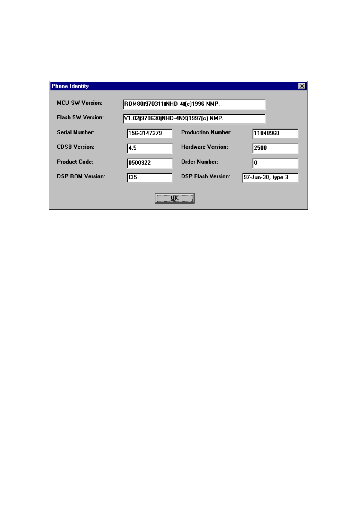
View Menu
Phone Identity
NHP–4
This option displays the following phone identity fields:
– ROM version
– Flash version
– Production Serial Number (PSN),
– Order Number,
– Product Code,
– Hardware ID.
Issue 1 04/99
Page 49
Page 50
WinTesla Users Guide
PAMS
NHP–4
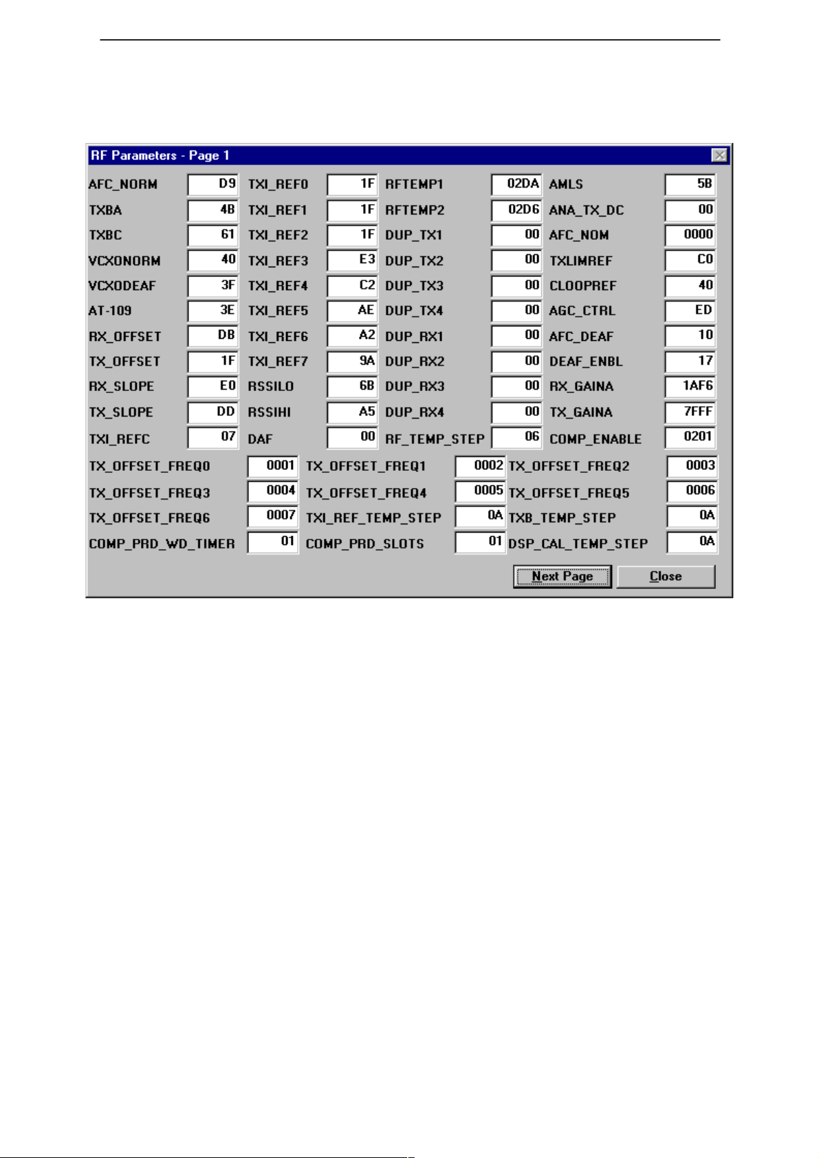
RF Parameters
Technical Documentation
This dialog shows the RF parameters of the phone. Looking at these
parameters can help the technician in making decisions about the status
of the phone.
Page 50
Issue 1 04/99
Page 51
PAMS
WinTesla Users Guide
Technical Documentation
Help
Index
A comprehensive list of all WinTesla features, hypertext linked.
General Help (F1)
This option contains two options:
– Help on using WinTesla
– Help on using Help
Using Help
This option provides you with information on using the online help
function.
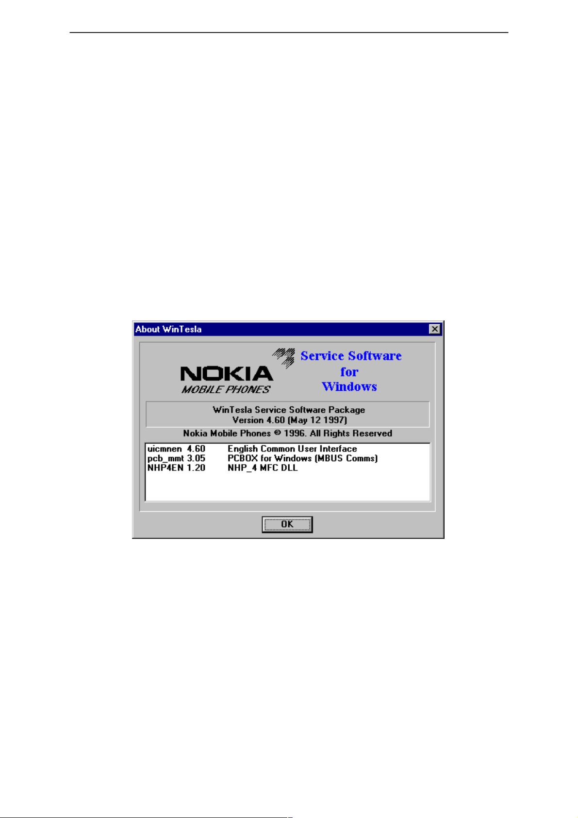
About WinTesla
Displays information on the the version that is running.
NHP–4
Issue 1 04/99
Page 51
Page 52

WinTesla Users Guide
PAMS
NHP–4
Common Problems
This section is a reference of known commo problems that may be
encountered when working with the Wintesla software package.
Setting up the computer Hardware
In order to avoid some common hardware problem, please ensure the
computer hardware is set up as follows.
COM Port Set up
COM port address (COM1 or COM2) should be set as the default values
for these ports. Special port address or IRQ settings may encounter
problems. to test this case set up a COM port as the default values and
try running the Wintesla application again.
Printer port set up
The printer port is used to attach the PKD–1 software Protection Key.
This device should work properly with most printer port settings.
However, if a problem is encountered, change the computer printer port
(LPT–1) setting to “Standard AT type”. This is NOT a Bi–directional
setting.
Technical Documentation
NOTE: When using an FPS–3C flash programming set, the printer port MUST be set
as “Standard AT Type”. The Flash box (FPS–3C) must have power connected.
Common Errors
Error – Functionality DLL not found
This error will be encountered if a phone is connected to WIntesla and it
is not recognized.
Solution
Install the Service Module for the phone type connected to Wintesla.
Contact your local Nokia vendor for information on how to obtain this
Service Module.
Error – PKD–1 not found
PKD–1 is the software Protection Key Device that is required for the
Wintesla application to run. This error will be encountered if the PKD–1
device is not installed on your printer port (LPT–1).
Solution
Attach the PKD–1 to the printer port (LPT–1) of the PC running Wintesla.
Page 52
Error – System hangs or Locks up
Wintesla may hang or Lock up if it is being run on Windows 95 or NT.
Solution
Run the Wintesla application on Windows 3.1 or 3.11. The Wintesla
application is NOT designed to run under Windows 95 or NT. If you are
using Windows 3.1 or 3.11 and are still experiencing problems please call
your local Authorized Service & Support location.
Issue 1 04/99
Page 53

PAMS
WinTesla Users Guide
Technical Documentation
Error – Reset FPS–3 box
This error only occurs when reflashing a phone with new software.
Solution
Remove power from the FPS–3C box for approximately 5 seconds. Then
reconnect power.
Error – Phone will not Tune properly
The phone can not be properly Tuned while connected to the FPS–3C
flash box. The voltage coming from the box will cause errors in the tuning
parameters.
Solution
Disconnect the FPS–3C box from the phone while Tuning. Only use one
of the set up configurations listed in the Dealer Setups section of the
NHD–4NX Service Manual.
Service and Support
NHP–4
Please contact your local Service location for more information and
support .
Or try our web site (http://www.Nokia.com)
Issue 1 04/99
Page 53
Page 54

WinTesla Users Guide
PAMS
NHP–4
Technical Documentation
[This page intentionally left blank]
Page 54
Issue 1 04/99
 Loading...