

Page 1

TUNING INSTRUCTIONS
NHC–4
Contents
Tuning Instructions 6–3–2
General 6–3–2
Required Equipment 6–3–3
Accuracy of the Equipment During Measurement 6–3–3
Equipment Setup 6–3–4
Equipment Setup for Tuning a Phone without Removing Covers 6–3–5
Equipment Setup for Tuning a Phone Removing Covers 6–3–6
Equipment Setup For Tuning A Booster 6–3–7
Starting The Program 6–3–8
Starting options for service software 6–3–8
Tuning Steps of Radio Unit 6–3–9
1. Bias Current Tuning 6–3–9
2. TX Output Power 6–3–10
3. FM Modulator Tuning 6–3–11
4. AFC tuning 6–3–12
5. RFI TX–IQ D.C. Offset Tuning 6–3–13
6. AMPS Demodulation Tuning 6–3–14
7. Analog mode RSSI 6–3–15
8. Digital mode AGC 6–3–16
9. Battery Voltage Adjustment 6–3–17
10. Charge Voltage Adjustment 6–3–17
11. SINAD Level Checking 6–3–18
Tuning Steps of Booster 6–3–19
1. Output Power Tuning 6–3–19
2. Transmitter Frequency Tuning 6–3–20
3. Output Power Check 6–3–21
4. Receiver Calibration 6–3–22
5. Voltage Calibration 6–3–22
9618ARo
Technical Documentation
6–3–1
Copyright Nokia Mobile Phones
Page 2

TUNING INSTRUCTIONS
NHC–4
9618ARo
Technical Documentation
Tuning Instructions
General
In contrast to earlier second–generation analog cellular phones tuning operations of the NHC–4 are carried out using the Service software. The Service program turns the phone into the Locals mode, in which the phone can be outwardly controlled via the M2BUS interface.
The tuning values of the phone reside on the EEPROM. Before tuning these
values are read to the Service software and the user can change these values
with tuning functions.
N.B. During tuning, proceed as follows:
– Take care not to damage sensitive measuring instruments with excessive
RF power.
– Carry out all tuning steps in the shortest possible time to avoid excessive
heating of RF units.
6–3–2
Copyright Nokia Mobile Phones
– Perform all tuning steps in the order presented.
– Never try to mask a fault by tuning it out!
Page 3

TUNING INSTRUCTIONS
NHC–4
Required Equipment
– PC/AT computer with the Service software; see Sect. 5 for intructions on
installation and use.
– M2BUS adapter DAU–2 and other service accessories; see equipment set-
up pictures.
– Audio analyzer
– Spectrum analyzer
– RF power meter, power measurement sensitivity –10 dBm.
– Modulation analyzer with precise frequency measurement.
– RF generator
– Device to provide specified testmodulation to modulate RF generator.
– DMR tester
– Multimeter or DVM.
9618ARo
Technical Documentation
6–3–3
Copyright Nokia Mobile Phones
– Attenuator and branching unit.
– Power supply 1, nom. voltage 12 V.
– Power supply 2, nom. voltage 6 V. This is needed only in that case, if you
want to connect the dummy battery direct to the to power supply.
Accuracy of the Equipment During Measurement
– Power supply 1; nominal voltage 12 ±0.5 V current cap. min. 1.5 A for ser-
vice box (JBS–7). If you test or tune also the RF booster BSH–4, you need
power supply, which has 5 A output capacity.
– Power supply 2 ;nominal voltage 6.0 ±0.1 V, current cap. min. 1.5 A.
– Mod. analyzer power level resolution 0.1 dB, accuracy ±0.5 dB. Frequency
counter accuracy 0.1 ppm 〈±80 Hz).
– RF generator; frequency res. 10 Hz amplitude res. 0.1 dB frequency stab.
±0.25 ppm.
– Spectrum analyzer; dynamic range 70 dB, accuracy ±1 dB (For power level
measurement accuracy ±0.5 dB).
Page 4

TUNING INSTRUCTIONS
NHC–4
Equipment Setup
Caution: Make sure that you have switched off the PC and the printer before
making connections !
Caution: Do not connect the PKD–1 key to the serial port. You may damage
your PKD–1 !
Attach the protection key PKD–1 to parallel port one (25–pin female D–connector) of the PC. When connecting the PKD–1 to the parallel port be sure that you
insert the PC end of the PKD–1 to the PC (male side). If you use a printer on
parallel port one, place the PKD–1 between the PC and your printer cable.
Next connect the M2BUS adapter to the serial port (RS–232) of the computer.
In case you are using a 9–pin serial port (normal with an AT set) use the mating
adapter supplied with the M2BUS adapter.
Attach one end of the XCM–1 modular cable to the DAU–2 PC/M2BUS adapter
and the other end to the JBS–7 service box. Use suitable adapter, SCS–1 service cable when the covers of the phone are in place, JBS–8 test frame with the
phone covers off, and attach it to the phone. Then connect it to the service box.
9618ARo
Technical Documentation
6–3–4
Copyright Nokia Mobile Phones
Page 5
TUNING INSTRUCTIONS
NHC–4
9618ARo
Technical Documentation
Copyright Nokia Mobile Phones
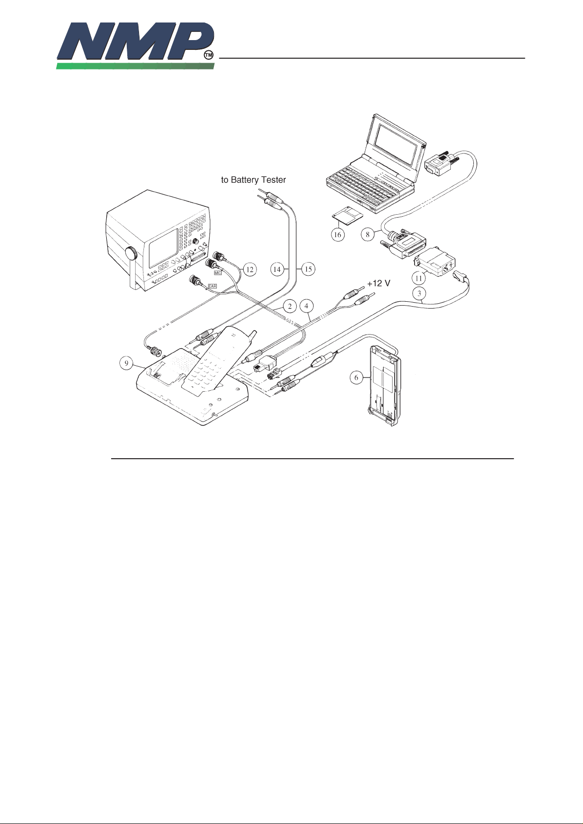
Equipment Setup for Tuning a Phone without Removing Covers
6–3–5
Item: Service accessory: Product code:
2 Audio cable, ADS–1 0730011
3 Modular cable, XCM–1 4626131
4 Power connector, PCS–1 0730012
6 Dummy battery, BTS–4 0770009
8 RS–232 adapter (9 pin to 25 pin) 4626170
9 Service box, JBS–7 0770015
11 PC/M2BUS adapter, DAU–2 0750006
12 BCN cable (not available)
14 Banana cable (not available)
15 Banana cable (not available)
16 Service software diskette 3.5” 0774003
16 Service software diskette 5.25” 0774004
– Software protection key PKD–1 ”dongle” 0750018
Page 6
TUNING INSTRUCTIONS
NHC–4
9618ARo
Technical Documentation
Copyright Nokia Mobile Phones
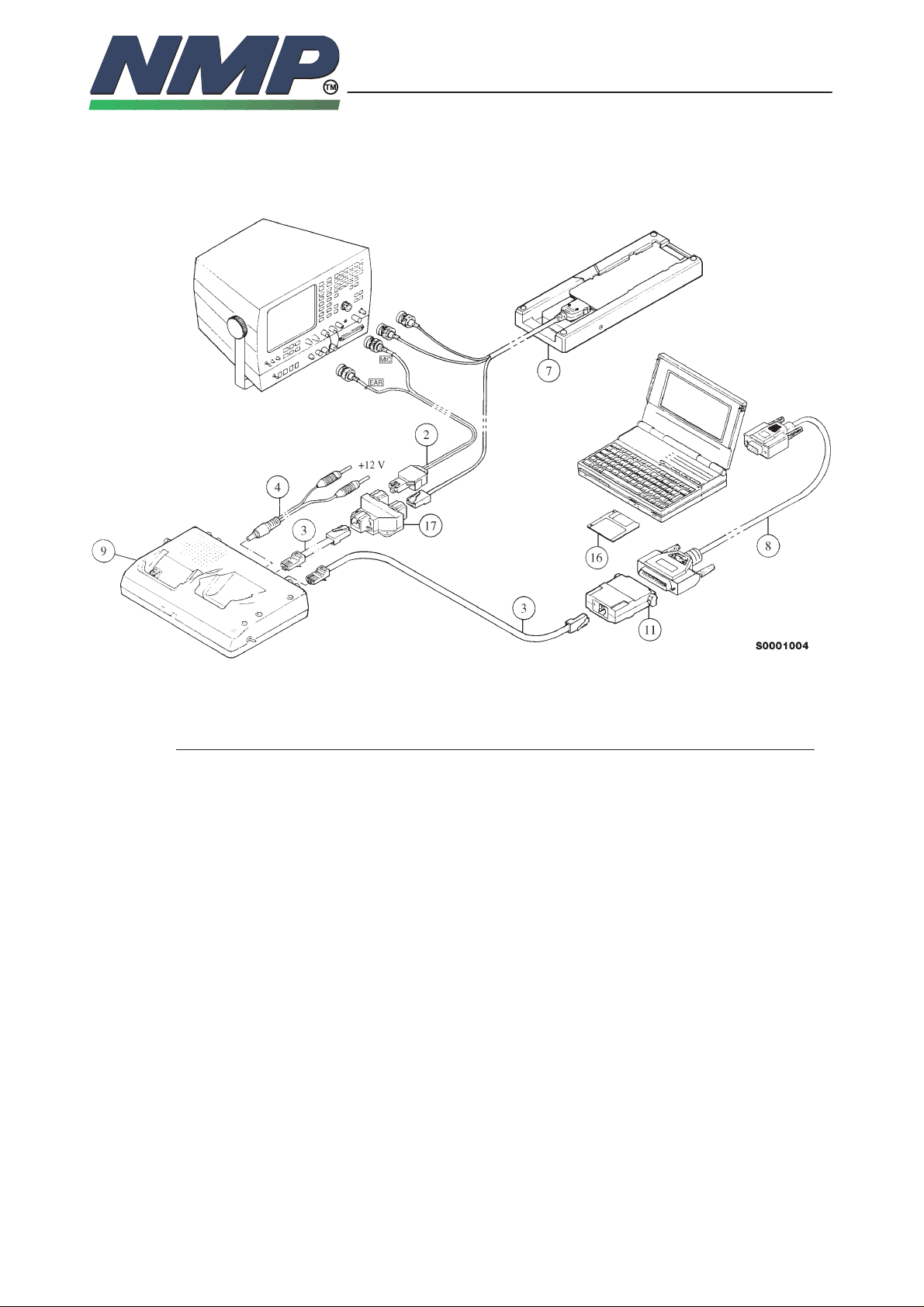
Equipment Setup for Tuning a Phone Removing Covers
6–3–6
Item: Service accessory: Product code:
2 Audio cable, ADS–1 0730011
3 Modular cable, XCM–1 4626131
4 Power connector, PCS–1 0730012
7 Test frame, JBS–8 0770014
8 RS–232 adapter (9 pin to 25 pin) 4626170
9 Service box, JBS–7 0770015
11 PC/M2BUS adapter, DAU–2 0750006
16 Service software diskette 3.5” 0774003
16 Service software diskette 5.25” 0774004
17 Modular T–connector 4626134
– Software protection key PKD–1 ”dongle” 0750018
Page 7
TUNING INSTRUCTIONS
NHC–4
9618ARo
Technical Documentation
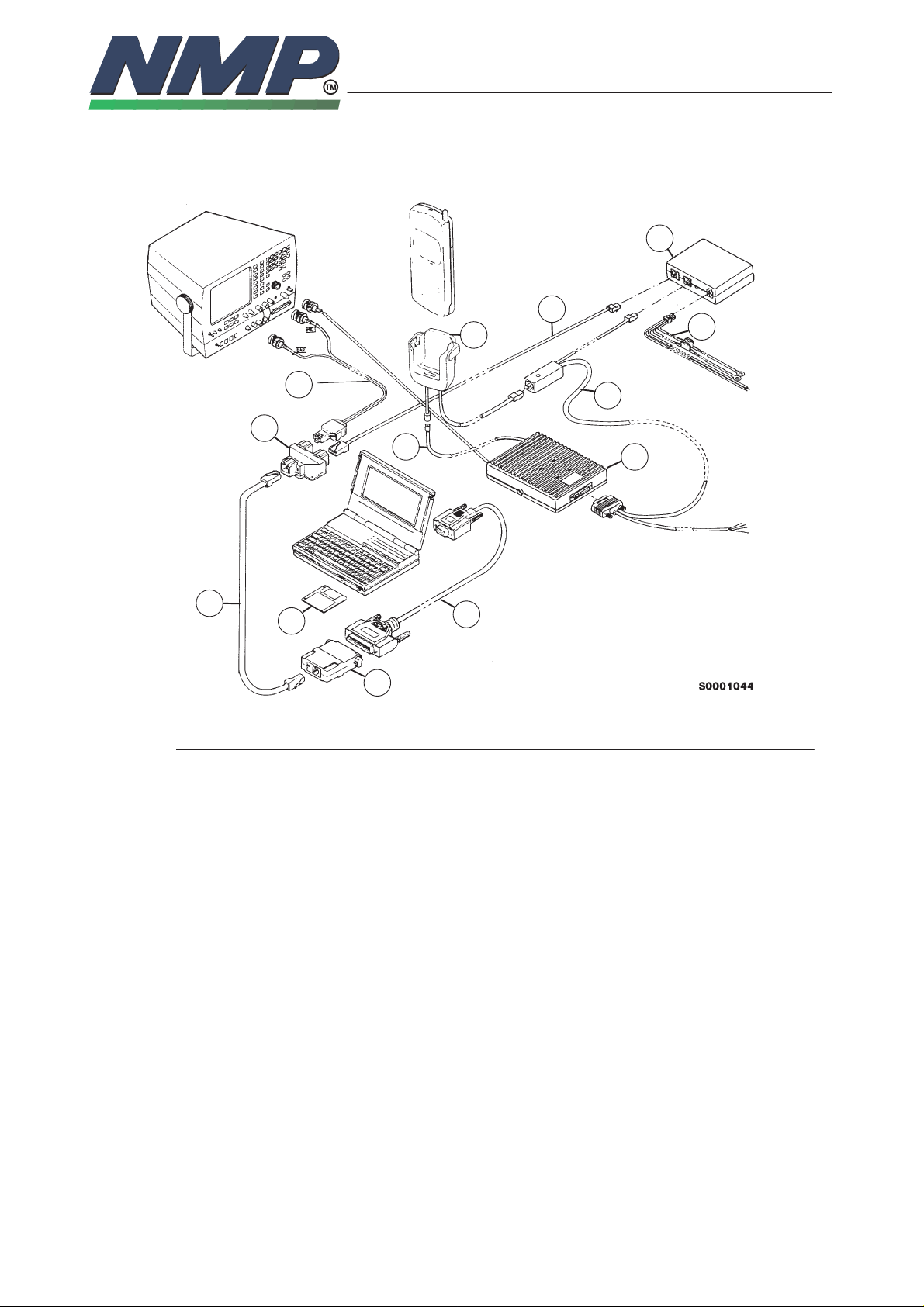
Equipment Setup For Tuning A Booster
20
2
17
5
6–3–7
Copyright Nokia Mobile Phones
21
3
22
19
18
3
16
11
8
Item: Service accessory: Product code:
2 Audio cable, ADS–1 0730011
3 Modular cable, XCM–1 4626131
5 RF extension cable, XRH–1 0730017
8 RS–232 adapter (9 pin to 25 pin) 4626170
11 PC/M2BUS adapter, DAU–2 0750006
16 Service software diskette 3.5” 0774003
16 Service software diskette 5.25” 0774004
17 Modular T–connector 4626134
18 Booster, BSH–4 0500188
19 Front mount cable, SCE–8 9780091
20 Mobile holder, MCH–8 0620010
21 HF junction box, HFJ–3 0694009
22 Power cable, PCH–4 0730009
– Software protection key PKD–1 ”dongle” 0750018
Page 8

TUNING INSTRUCTIONS
NHC–4
9618ARo
Technical Documentation
Starting The Program
The program is delivered on a diskette and is copy protected with a dongle.
The program can also be installed on the hard disk, which is recommendable to
obtain a maximum data access rate. In case you want to store the program to
the hard disk, proceed according to instructions given in the Service software
installation manual.
The program is started with the command:
NHC4SERV <Enter> (or PCLSTART <Enter>)
The program can be set up work with different serial ports or display types.
Starting options for service software
The program is started by entering the following command:
NHC4SERV
For more information about how to operate the Service software, refer to section 5: Service software.
6–3–8
Copyright Nokia Mobile Phones
Page 9

TUNING INSTRUCTIONS
NHC–4
9618ARo
Technical Documentation
Tuning Steps of Radio Unit
1. Bias Current Tuning
The purpose of this tunig is to optimize transmitter‘s efficiency.
Bias tuning is needed if:
– PLL circuit (N501) is replaced
– any of power amplifiers (CLY5, CCY15) duplex filter is replaced
– any of power amplifiers resistors is replaced
This affects only power consumption and thus gain and linearity of power amplifier.
Analog bias current tuning:
– Start the service software and go to ”Main” menu.
– Select ”Service – Tunings – Bias current tunings”
– Measure step1 current consumption from power supply current display and
input it to Service software prompt.
6–3–9
Copyright Nokia Mobile Phones
– Adjust first analog mode bias current to the target value displayed in tuning
dialog by using arrow– or PgUp/PgDwn –keys.
Digital bias current tuning:
– Change to digital mode bias tuning with <Tab> and proceed as in analog
mode tuning.
After this digital bias tuning the TX linearity can be checked: the highest peak
+ 24.3 kHz peak should be 29.5 dB below the highest peak. Adjust spectrum
analyzer: center frequency; 848.7 MHz, Span; 100 kHz, Res BW; 1 kHz
– Press <Enter> to store the value to the phone and exit or <Esc> to exit with-
out storing.
Page 10

TUNING INSTRUCTIONS
NHC–4
2. TX Output Power
This adjustment loads the power levels of the phone transmitter into EEPROM.
When doing this, a power meter must be used. The phone is in analog mode in
this tuning for making the power measurement easier than in digital mode.
This tuning is needed if RFI, CRFRT, duplex filter, power RF transistors or power control parts are replaced
Power levels programming:
– Set power supply voltage to 6.0 V.
– Select ”Service – Tunings – TX output power tuning band 1”
– Connect power meter to antenna connector.
– Adjust tuning value with arrow keys (fine tuning) or with PgUp and PgDn–
keys (coarse tuning) until the desired output power is reached. Tuning starts
from the lowest power level.
– Note: There is a little cable loss between the antenna connector and the RF
power meter. The total attenuation of 1 meter long RG–58 cable and the
service box is about 0.7 dB.
9618ARo
Technical Documentation
6–3–10
Copyright Nokia Mobile Phones
Power
level
Power level of
band 1
Example value
D/A converter
10 –4.2 (0.38 mW) –170
9 –0.2 (0.95 mW) –125
8 3.8 (2.40 mW) –61
7 7.8 (6.03 mW) –161
6 11.8 (15.1 mW) –129
5 15.8 (38.0 mW) –89
4 19.8 (95.5 mW) –40
3 23.8 (239.9 mW) 0
2 26.8 (479 mW) 143
– Press <Tab> key twice to change the power level 8.
– Adjust power levels 10,8,6 and 2 from band 1. (The levels in brackets on the
display are not needed to tune)
– Press <Enter> to store values to the phone and exit or <Esc> to exit without
storing.
– Select ”Service – Tunings – TX output power tuning band 2” and tune power
level 2 and 8 only. Press <Enter> to store values to the phone and exit.
– Repeat procedure on bands 3 and 4.
– Select ”Service – Tunings – Calculate power tables ”
Page 11

TUNING INSTRUCTIONS
NHC–4
– Program calculates all other tuning levels. After all tables are calculated you
must check that actual power level on bands 2–4 are correct.
– Press <Enter> to store calculated values to the phone and exit or <Esc> to
exit without storing.
3. FM Modulator Tuning
This tuning is done to adjust the FM Modulators 0dB level and the gain of TX–
audio path.
This tuning is needed if Codec N150, or components V550, N540 and V570 is
changed. VHF has no effect on this
FM Modulation adjustment:
– Select ”Service – Tunings – FM Modulation”
– Connect modulation analyzer to antenna connector. Use 15 kHz lowpass
filter.
9618ARo
Technical Documentation
6–3–11
Copyright Nokia Mobile Phones
– Measure +/– peak per 2 deviation (filter 300 Hz wide) and adjust it with ar-
row– or PgUp/PgDwn keys to 8.2 kHz +/– 200 Hz. (ST signal is switched
ON)
– Continue to next field with <Tab>
– Adjust the gain value so that FM peak deviation is 3.1 kHz +/– 100 Hz. (In-
ternal 1 kHz test tone is switched ON)
– Press <Enter> to store values to the phone and exit or <Esc> to exit without
storing.
Page 12

TUNING INSTRUCTIONS
NHC–4
4. AFC tuning
This tuning is done to calibrate the VCTCXO oscillator frequency.
This tuning is needed if VCTCXO, any component of AFC–line (R457, R458,
V451) or RFI is changed.
AFC calibration:
– Select ”Service – Tunings – AFC Tuning”
– Connect the modulation (or spectrum) analyzer to antenna connector and
measure transmitter frequency. Adjust frequency to 831.0 MHz +– 80Hz with
arrow or PgUp/PgDwn –keys.
– Press <enter> to store value to EEPROM or <esc> to exit without saving.
9618ARo
Technical Documentation
6–3–12
Copyright Nokia Mobile Phones
Page 13

TUNING INSTRUCTIONS
NHC–4
9618ARo
Technical Documentation
5. RFI TX–IQ D.C. Offset Tuning
The purpose of this tunig operation is to adjust the I/Q modulator d.c. offsets
and the I/Q modulator amplitude balance and phase shift.
This tuning is needed if CRFRT or RFI circuit is changed.
I/Q modulator d.c. offsets:
– Connect spectrum analyzer (with attenuator if needed) to phone antenna
connector.
– Select ”Service – Tunings – TX IQ tuning”
– Adjust spectrum analyzer center frequency to 831 MHz, Span 50 kHz,
Res BW 300 Hz, Video BW 100 Hz and Sweep time AUTO. Do not do this
tuning without proper analyzer.
6–3–13
Copyright Nokia Mobile Phones
– Select option ”I offset” and adjust the level of center frequency to minimum
by arrow keys.
– Select option ”Q offset” and adjust the level of centre frequency to minimum
by arrow keys.
– After these two compensations center frequency attenuation must be at
least 32 dB otherwise repeat tuning.
– Press <Enter> to store values to the phone and exit or <Esc> to exit without
storing.
Page 14

TUNING INSTRUCTIONS
NHC–4
9618ARo
Technical Documentation
6. AMPS Demodulation Tuning
The purpose of this tuning operation is to calibrate the gain of audio path.
This tuning is needed if FM detector (N702) including surrounding components
of FM detector or Audio Codec (N150) is changed
Demodulation adjustment:
– Select ”Service – Tunings – AMPS demodulation”
– Apply modulated test signal (ch 200, RX frequency 876.000 MHz, modula-
tion 1 kHz with 5.8 kHz deviation and RF level –80 dBm) to antenna connec-
tor.
– Adjust tuning value with arrow keys (fine tuning) or with PgUp and PgDn–
keys (coarse tuning) until measured EAR level is 310 mVrms +/– 5mV.
– Press <Enter> to store values to the phone and exit or <Esc> to exit without
storing.
6–3–14
Copyright Nokia Mobile Phones
Page 15

TUNING INSTRUCTIONS
NHC–4
7. Analog mode RSSI
This step consist of tuning the analog mode reference value for the receiver
signal strenght meter.
This tuning is needed if FM detector; any parts of RX–chain; duplex filter, saw
filter or chrystal filter has been changed
Note: Take account the cable losses.
Analog RSSI level tuning:
– Connect signal generator to antenna connector at 882 MHz (channel 400)
using modulating frequency 1.0 kHz with a deviation of 8.0 kHz and level of
–90 dBm.
– Select ”Service – Tunings – Analog Mode RSSI”.
– The program reads the reference value stored on phone together with the
reference value read from A/D converter.
– A/D converter value should be 240 – 340.
9618ARo
Technical Documentation
6–3–15
Copyright Nokia Mobile Phones
– Press <Enter> to store values to the phone and exit or <Esc> to exit without
storing.
Page 16

TUNING INSTRUCTIONS
NHC–4
8. Digital mode AGC
This step consist of tuning the receivers gain in digital mode as a function of
AGC. AGC values are tuned at four different RF levels: –100 dBm, –90 dBm,
–70 dBm and –65 dBm.
This tuning is neded if CRFRT, RFI, common parts of RX–chain or duplex filter
is changed
AGC tuning:
– Select ”Service – Tunings – Digital mode AGC”
– Connect signal generator to antenna connector at 883.353 MHz (channel
445 + 3.0 kHz) with no modulation and level of –100 dBm.
– Change the tuning value with arrow– or PgUp/PgDwn –keys until the value
in ”Coarse error” field is as close to zero as possible. +–3 is acceptable if
zero cannot be reached. ”Coarse error” and ”Fine error” fields are updated
after each change in tuning value.
9618ARo
Technical Documentation
6–3–16
Copyright Nokia Mobile Phones
– Fine tune value by continuing adjusting until value in ”Fine error” –field is as
close to zero as possible. This value may not allways get closer than +–100.
– Change RF –level to –90 dBm.
– Continue to the next fields with <Tab> and tune the –90 dBm,–70 dBm and
–65 dBm levels in the same way as previous step.
– Press <Enter> to store values to the phone and exit or <Esc> to exit without
storing.
Note: The cable losses are needed to take into account.
Page 17

TUNING INSTRUCTIONS
NHC–4
9618ARo
Technical Documentation
9. Battery Voltage Adjustment
A reference value for battery are calibrated by using an accurate 6.0 V supply.
Calibration of the A/D converter channels:
– In case the phone covers are not removed replace the standard battery
of the phone with the dummy battery BTS–4.
– Apply +6 V to dummy battery.
– Select ”Service – Tunings – Battery voltage tuning”.
– Program rads 6 V, A/D reading fed to phone VBATT line.
– Store correct value to phone EEPROM by pressing <Enter>
10. Charge Voltage Adjustment
A reference value for charge voltage is set by using an accurate 6.0 V supply.
Calibration of the charge voltage:
6–3–17
Copyright Nokia Mobile Phones
– In case the phone covers are not removed replace the standard battery of
the phone with the dummy battery BTS–4.
– Apply +6 V to VCHARG line.
– Select ”Service – Tunings – Charge voltage tuning”.
– Program rads 6 V, A/D reading fed to phone VCHARG line.
– Store charge voltage value to phone EEPROM by pressing <Enter>
Page 18

TUNING INSTRUCTIONS
NHC–4
11. SINAD Level Checking
You should only check the sinad value! Sinad is only checked, not tuned!
If the sinad is poor, you must repair the phone, see section testing and trouble-
shooting.
SINAD level tuning:
– Connect signal generator to antenna connector at 876.000 MHz (channel
200) using modulating frequency 1.0 kHz with a deviation of 8.0 kHz and
level of –116 dBm.
– Note: Take into account the losses of the cables
– Select ”Service – Tunings – AMPS Demodulation”
– Do not use the settings for RF generator which are on the display
– Set TX ON
– Connect SINAD meter to XEAR line
9618ARo
Technical Documentation
6–3–18
Copyright Nokia Mobile Phones
– Psophometrically weighted SINAD values should be more than 12 dB.
Page 19

TUNING INSTRUCTIONS
NHC–4
9618ARo
Technical Documentation
Tuning Steps of Booster
1. Output Power Tuning
In output power calibration we have to find the D/A converter values for given
output power. Values are then saved to the EEPROM.
In booster EEPROM there is a table for 31 power levels. The power levels are
from 4.8 to 34.8 dBm in1 dB steps.
The purpose of the calibration is to adjust the D/A value so that the power meter shows the correct dBm value and then save the D/A value to EEPROM.
Output power can be tuned by following these steps:
– Connect the phone and the accessories as shown in picture Equipment Se-
tap For Tuning A Booster. Connect the RF power meter to the antenna con-
nector of the Booster.
– Booster is initialized when the ”Output power tuning” is selected from
”Booster tuning” menu.
6–3–19
Copyright Nokia Mobile Phones
– When the booster is connected to the full handsfree car kit, the transmitter
of the phone is at powerlevel 5, so the input signal to the booster is about 13
dBm at all powerlevels.
– Adjust the output power by using arrow keys or by clicking corresponding
buttons. Try to get the output power value to nearest 0.2 dB.
– After the output power is correct, proceed to the next power level by select-
ing ”Next level” and tune the power to new target value.
– When all the levels are tuned, you can save the values to booster EEPROM
by pressing <Enter>. If you press <Esc> changes are not saved to booster
EEPROM.
Page 20

TUNING INSTRUCTIONS
NHC–4
9618ARo
Technical Documentation
2. Transmitter Frequency Tuning
After the output power levels have been calibrated in the middle channel
(836MHz) the amplification must also be calibrated in different frequencies.
Frequency calibration is made in 5 different frequencies: 824 MHz, 830 MHz,
836 MHz, 842 MHz and 848 MHz.
There is a table in booster EEPROM where the differences between middle
channel output and output on given channel is stored.
Here is how to calibrate booster on different frequencies:
– Connect the booster and the cables as in the output power tuning.
– Select Transmitter frequency tuning from booster menu. Booster is initialized
when the tuning dialog appears.
– The phone is operated as preamplifier generating the inout signal to the
booster. Channel and frequency is displayed in the help window of tuning
dialog.
6–3–20
Copyright Nokia Mobile Phones
– Read the output power from RF meter and press ”Input value” button. An
input dialog appears where you can input the measured power level.
– Accept the inputted value with <Enter> or cancel it with <Esc>.
– When the value is inputted, the frequency in help window changes to the
next tuning frequency.
– When power levels are inputted on all the frequencies, you can store the
values to booster by pressing <Enter> or cancel tuning by pressing <Esc>.
Page 21

TUNING INSTRUCTIONS
NHC–4
3. Output Power Check
After the transmitter calibration you must check that the output power is correct
in all input levels and input voltages. Error of –1 dB to +1 dB is acceptable. Also
the surge protection of the PA module must be checked. It should operate
when the input voltage goes over 16 V.
Output power check:
– Connect the booster and the cables as in the output power tuning.
– Use 10.5 V as booster input voltage.
– Select ”Output power check” from booster menu. Booster is initialized when
the testing dialog appears.
– Measure the output power. Power should be within the limits displayed in
the help window of testing dialog. Difference of –1 dB, +1 dB is acceptable.
– Select next power level by pressing ”Next” button, and continue as ex-
plained in previous step.
9618ARo
Technical Documentation
6–3–21
Copyright Nokia Mobile Phones
– When all the power levels are checked repeat the steps using voltage of
15 V. The output level must not be over +1 dB of the nominal.
– Check that the output power drops to zero when the input voltage is set over
16 V.
Page 22

TUNING INSTRUCTIONS
NHC–4
4. Receiver Calibration
Receiver operates in frequencies 869 to 894 MHz. Receiving part is always on
if the booster has the power connected.
The receiver has net gain of about +7 dB and it must be measured with ±1 dB
accuracy.
Calibration procedure is following:
– Inject the RF power to output of the booster and measure the amplification
from the input.
– Set the output power of the RF generator to –50dBm.
– Set RF generator frequency to 869.0 MHz.
– Read the output power from RF meter and press ”Input value” button. An
input dialog appears where you can input the measured power level.
– Accept the inputted value with <Enter> or cancel it with <Esc>.
– When the value is inputted, the frequency in help window changes to the
next tuning frequency. Tune RF generator to that frequency and proceed as
in previous step.
9618ARo
Technical Documentation
6–3–22
Copyright Nokia Mobile Phones
– When power levels are inputted on all the frequencies, you can store the
values to booster by pressing <Enter> or cancel tuning by pressing <Esc>.
5. Voltage Calibration
For temperature measurements the booster has internal NTC.
Temperature reading is used for compensations, shutdowns and alarms. For
accurate readings the NTC must be calibrated in one point by writing the calibration value to EEPROM.
Note: Before calibrating temperature, let the booster cool down long enough so
that the temperature measured from the surface of the booster is about the
same as the temperature inside the booster.
Calibration procedure is following.
– Select ”Temperature calibration” from booster tuning menu.
– Measure the booster temperature and input the measured value to the input
dialog.
– Accept the value by pressing <Enter> or cancel tuning by pressing <Esc>.
 Loading...