

Page 1

Nokia Customer Care
2115i/2116/2116i (RH-66)
Mobile Terminals
Antenna Description and
Troubleshooting
Issue 1 03/2005 Company Confidential ©2005 Nokia Corporation
Page 2

2115i/2116/2116i (RH-66)
Antenna Description and Troubleshooting
Contents Page
Introduction ..................................................................................................................................................... 3
Visual Quality Requirements ....................................................................................................................3
Failures and Corrective Measures.............................................................................................................. 4
PIFA Antenna ................................................................................................................................................4
Damaged RF Feed or Ground Pins........................................................................................................ 5
Damaged IHF Speaker Pogo Pins.......................................................................................................... 5
Wrong Internal Antenna Installed ....................................................................................................... 5
Obstructed IHF Speaker, RF Feed, and Ground Pads............................................................................. 7
Grounding of Display Frame .....................................................................................................................8
RF Connector Failure .................................................................................................................................. 8
RUIM Card Flap Grounding .......................................................................................................................9
Testing the CDMA Antenna ...................................................................................................................... 10
Calibration Factors ....................................................................................................................................10
Calibration Factor for PCS1900 Frequency ........................................................................................10
Measurement Procedure .........................................................................................................................10
Testing the GPS Antenna (2115i/2116i) ............................................................................................... 11
Calibration Factor for GPS ......................................................................................................................11
Measurement Procedure .........................................................................................................................11
Page 2 ©2005 Nokia Corporation Company Confidential Issue 1 03/2005
Page 3

2115i/2116/2116i (RH-66)
Nokia Customer Care Antenna Description and Troubleshooting
Introduction
The mobile terminal incorporates an internal antenna. This antenna arrangement is used
for AMPS/Cell and PCS frequency bands. The internal antenna assembly consists of a
Planar Inverted-F Antenna (PIFA) used for the cellular engine and an Inverted-F antenna
(IFA) used for the GPS engine, which is placed on the side of internal antenna body.
Visual Quality Requirements
Following are the minimum acceptable visual quality requirements of the internal
antenna assembly:
• Gloves must be used when handling antennas. Do not touch the antenna radiator
with bare hands.
• No visual cracks or mechanical defects.
• No oil, dirt, or particles are present on the parts.
• Radiator must be aligned with the plastic housing.
• GPS antenna contacts must be inside the plastic housing.
• Radiator must be flat with no warping.
• All pins must be at the same level.
Issue 1 03/2005 ©2005 Nokia Corporation Company Confidential Page 3
Page 4
2115i/2116/2116i (RH-66)
Antenna Description and Troubleshooting
Failures and Corrective Measures
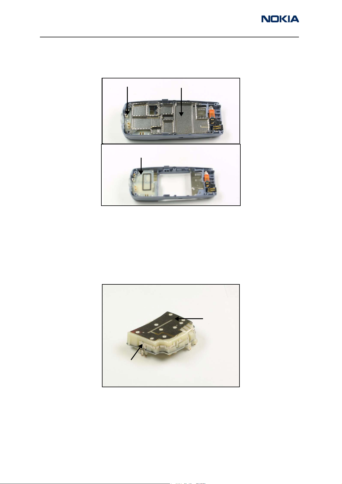
The internal antenna is assembled into the D-cover as shown in Figure 1. If no internal
antenna is installed, the antenna gain is degraded by more than 25 dB.
Internal antenna
Internal antenna
PWB shield
• If the internal antenna is missing, install one.
• If the radiator looks obviously damaged, replace the internal antenna.
PIFA Antenna
The internal antenna includes a planar-inverted F antenna (PIFA) radiator and an
inverted F antenna (IFA) radiator (GPS antenna radiator) attached to a plastic carrier. An
integrated hands-free (IHF) mini speaker is integrated inside the plastic.
Figure 1: D-cover assembly
Main antenna
radiator (PIFA)
GPS antenna
radiator (IFA)
Figure 2: Internal antenna
Note: The GPS antenna is only functional on the 6115i and 6116i models.
Page 4 ©2005 Nokia Corporation Company Confidential Issue 1 03/2005
Page 5

2115i/2116/2116i (RH-66)
Nokia Customer Care Antenna Description and Troubleshooting
Damaged RF Feed or Ground Pins
The main antenna and the GPS antenna have pins (spring clips) that must properly touch
the PWB.
• If the main antenna’s RF feed pin does not touch the PWB, the antenna gain
degrades by more than 25 dB and the GPS antenna is detuned.
• If the ground pin of the main antenna does not touch the PWB, the antenna gain
degrades from 5 to 10 dB and the GPS antenna is detuned.
• If the GPS antenna’s RF feed pin does not touch the PWB, then the GPS antenna
gain degrades by more than 20 dB.
• If the ground pin of the GPS antenna does not touch the PWB, the GPS antenna
gain may degrade by more than 5 dB.
Main antenna
RF feed pin
GPS antenna
ground pin
Main antenna
ground pin
Figure 3: Back view of the internal antenna
• If either the RF feed pin or ground pin are broken or bent such that either pin
does not touch the PWB, replace the internal antenna.
• If either the RF pin or ground pin springs appear damaged, replace the internal
antenna.
Damaged IHF Speaker Pogo Pins
In Figure 3, the two pogo pins on the back of the internal antenna must properly touch
the PWB. If not, the PCS gain of the internal antenna can degrade by 2 dB and no audio
will emit from the speaker.
Wrong Internal Antenna Installed
The internal antenna is mechanically similar to the one used in the 2112 mobile terminal.
Following are important differences between these antennas:
GPS antenna
RF feed pin
IHF mini speaker pogo pins
• The slot pattern is different.
• The feed/ground leg locations are different.
Issue 1 03/2005 ©2005 Nokia Corporation Company Confidential Page 5
Page 6

2115i/2116/2116i (RH-66)
Antenna Description and Troubleshooting
• The 2115i/2116/2116i includes a GPS antenna. The 2112 does not.
Note: GPS is functional only in the 2115i and 2116i.
• The main radiators for the 2115i/2116/2116i include markings that begin with an
“F”. The 2112 markings begin with a “C”.
2115i/2116/2116i
GPS antenna
Figure 4: Top view of the 2115i/2116/2116i (left) and 2112 (right) internal antennas
Installing the 2112 antenna in the 2115i/2116/2116i is not compliant with Nokia’s FCC
submission because the 2112:
2112
• Uses a single-band (no PCS)
• Does not have a GPS antenna
• Is not tuned correctly for the 2115i/2116/2116i mechanics
• Does not make contact with the feed/ground pads on the PWB
Use the following to troubleshoot the internal antenna:
• If the wrong antenna is installed, install the correct one.
• If the slot in the radiator has a significantly different shape, install the correct
internal antenna. Be aware that the shape of the slot can vary slightly. The length
of the horizontal slot and the opening of the vertical slot can vary by a few
millimeters because the antennas are tuned for each batch of plastic frames.
• If there are other obvious damages to the radiator (e.g., dents and corrosion),
replace the antenna.
• If the pin is stuck or has excessive friction with the plastic tube/guiding feature,
the spring will not work properly. Replace the antenna.
Page 6 ©2005 Nokia Corporation Company Confidential Issue 1 03/2005
Page 7

2115i/2116/2116i (RH-66)
Nokia Customer Care Antenna Description and Troubleshooting
Obstructed IHF Speaker, RF Feed, and Ground Pads
RF feed pad for GPS antenna
IHF speaker
pads
Ground pad
for main
antenna
RF feed pad
for main
antenna
Figure 5: PWB layout of IHF speaker, RF feed, and ground pads
Ground pad for GPS antenna
If any of the RF feed or ground pins are obstructed, removed, or covered, the RF pin does
not touch the PWB and the antenna performance degrades. If any of the IHF speaker
pads are obstructed, removed, or covered, the speaker’s pogo pin does not touch the PWB
and the PCS antenna performance could degrade. See the "Damaged IHF Speaker Pogo
Pins" section for antenna performance degradation if any pogo pin does not touch the
PWB.
• If corrosion is present or the pad is missing, replace the mobile terminal.
• If a pad is obstructed or covered, clear and/or clean the pad.
Issue 1 03/2005 ©2005 Nokia Corporation Company Confidential Page 7
Page 8

2115i/2116/2116i (RH-66)
Antenna Description and Troubleshooting
Grounding of Display Frame
The display frame is grounded to the PWB through two ground panels. The display frame
grounding impacts the radiation performance of the mobile terminal.
Display frame
grounding
through screws
Display frame
grounding tabs
• If the clips do not touch the PWB, are corroded, or are obstructed, replace the
display frame.
RF Connector Failure
The RF connector fails when it does not properly connect the RF input to the RF output.
If this happens the antenna gain degrades by 25 dB. Check this by testing for DC
conductivity between the RF input and RF output of the RF connector.
Note: Perform the DC conductivity test without a cable attached to the RF
connector. Because the RF connector is also a switch, the RF output is disconnected
from the RF input when a cable is inserted into the RF connector.
• RF input - Connector to the duplexer
Figure 6: Display assembly ground points
• RF output - Connects to the antenna pad through vias
• RF connector - Connects to a coaxial cable
If the RF input is not connected properly to the RF output, replace the RF connector.
Page 8 ©2005 Nokia Corporation Company Confidential Issue 1 03/2005
Page 9

2115i/2116/2116i (RH-66)
Nokia Customer Care Antenna Description and Troubleshooting
RUIM Card Flap Grounding
The RUIM card flap must be grounded to the RF shield with a conductive sticker.
Disassembling the RF shield from the chassis damages the sticker. You must remove the
sticker to change the antenna module or the RUIM card flap. If the sticker is damaged or
missing, then the radiated sensitivity at maximum power could be reduced by 1-2 dB.
• If the conductive sticker is missing or ripped, replace it.
• If the RF shield is replaced, install new labels (type labels) and a new conductive
sticker. If the conductive sticker is located underneath other labels, then it may
be necessary to replace all other labels as well.
Conductive
RF shield
sticker
RUIM card flap
Figure 7: Conductive sticker grounding the RUIM card flap to the RF shield
Issue 1 03/2005 ©2005 Nokia Corporation Company Confidential Page 9
Page 10

2115i/2116/2116i (RH-66)
Antenna Description and Troubleshooting
Testing the CDMA Antenna
Calibration Factors
Use the MJF-28 Docking Station Adapter to define the CPL-8 Antenna Coupler
calibration numbers. Obtain the calibration numbers by utilizing a mobile terminal with
known RF and antenna performance. Each test adapter should only require a single
calibration on PCS1900 and GPS bands at used test frequencies. Additional calibrations
should only be needed if the test adapter is substantially modified (reassembled, changed
parts, dropped, etc.).
Calibration Factor for PCS1900 Frequency
Use a call box to turn on the mobile terminal’s transmitter with a known output power
and antenna performance at the maximum output power (all bits up). Measure the
transmitted power on the RF connector and through a coupler at CDMA PCS channel
1175. Use the difference between the transmitted and received powers as the calibration
number (path loss on Cell band including coupler, cable, and attenuator path losses) for
the coupler on Cell band.
The nominal value for power measured at the RF connector is 23 dBm. The coupler path
loss is normally from 17 to 18 dB at the PCS band. If you use a 10 dB attenuator and a
cable with ~1 dB loss, the total path loss is from 28 to 29 dB and the measured power
should be from -5 to -6 dBm [23 dBm - (28…29 dB)]. However, you must measure path
loss separately for every coupler because path losses vary depending on the setup, cables,
and attenuator.
Measurement Procedure
Use the following measurement procedures for 800/1900 mobile terminals:
1. Place the mobile terminal in the MJF-28 Docking Station Adapter with the
display facing upward and its whip retracted.
2. Turn on the mobile terminal's transmitter at the PCS band on CDMA mode
channel 1175 at maximum output power (nominal 23 dBm at RF connector).
3. Measure the RF power with a CPL-8 Antenna Coupler. This represents the internal
antenna to RF coupler measurement.
4. Turn the mobile terminal's transmitter off.
The CDMA antenna test fails if the measured power is outside the test limits.
Table 1: CDMA Measurement Test Limits
Min Measured Power + Coupler,
Cable and Attenuator Path Loss
20,0 dBm 23 dBm 26,0 dBm
Page 10 ©2005 Nokia Corporation Company Confidential Issue 1 03/2005
Nominal
Max Measured Power + Coupler,
Cable and Attenuator Path Loss
Page 11

2115i/2116/2116i (RH-66)
Nokia Customer Care Antenna Description and Troubleshooting
Testing the GPS Antenna (2115i/2116i)
Calibration Factor for GPS
In GPS test mode 3, the GPS receiver is fed with a CW signal. The GPS receiver should
report C/No ratio of 35 dBHz with a -110 dBm signal level on the RF connector
(-110 dBm + cable loss) at signal generator output. The reported C/No figure is recorded
with the signal fed to the RF connector. The C/No value is read with a coupler engaged.
Increase the GPS signal level until the same C/No value is recorded. Use the difference
between the CW signal levels at the generator as the calibration number (path loss on
GPS band including coupler, cable, and attenuator losses).
The nominal coupler path loss at GPS band is 14 to 17 dB. If you use a 10 dB attenuator
and cable with 1 dB loss, the total path loss is 25 to 28 dB. The signal level at generator
output must be -85 to -82 dBm [-110 dBm -(-25 dB to -28 dB)]. However, the path loss
has to be measured separately for every coupler because the path losses vary depending
on the setup, cables, and attenuator.
Measurement Procedure
Use the following steps as a measurement procedure for the GPS Antenna:
1. Place the mobile terminal in the MJF-28 Docking Station Adapter with the
display facing up and the whip retracted.
2. Turn on the CW signal generator (with power -110 dBm + coupler, cable, and
attenuator path loss at GPS band) fed to the RF coupler.
3. Read the reported C/No figure with the test mode 3 three to four times to see if
it is stable.
The GPS antenna test fails if the C/No value is outside the test limits.
Table 2: GPS Antenna Measurement Test Limits
Min Nominal Max
31,0 dBHz 35,0 dBHz 38,5 dBHz
Issue 1 03/2005 ©2005 Nokia Corporation Company Confidential Page 11
Page 12

2115i/2116/2116i (RH-66)
Antenna Description and Troubleshooting Nokia Customer Care
This page intentionally left blank.
Page 12 ©2005 Nokia Corporation Company Confidential Issue 1 03/2005
 Loading...