

Page 1
Life Scope® SVM-7200 Series
Vital Signs Monitor
Clinical Reference Guide
Version 1
© 2019 All Rights Reserved
Page 2

Table of Contents
Introduction 1
Life Scope SVM-7200 Series Vital Signs Monitor 2
Front View 2
Le View 3
Right View 4
Top View (With Wireless LAN Module) 4
Rear View 5
Admitting a New Patient and Inputting Patient Information 6
Inputting the Patient ID 7
Inputting the Patient Name 8
Inputting the Date of Birth 9
Inputting the Height and Weight 10
Managing Patient Information 11
Discharging a Patient 12
In Continuous Mode 12
Saving and Sending Patient Information 14
Basic Operation 15
Modified Early Warning Score 16
Monitoring Parameters 17
NIBP Monitoring 17
Starting and Stopping NIBP 17
Changing NIBP Settings 17
NIBP Interval Settings 18
Venous Puncture Mode 18
Cu Size 19
Cu Positioning 19
us.nihonkohden.com
Page 3

Patient Type 19
Measuring Mode 20
SpO₂ Monitoring 21
Starting SpO₂ Measurement 21
Changing SpO₂ Settings 22
Temperature Monitoring 23
Exergen Temporal Scanner 23
Covidien Sensor 24
Applying Probe Covers 24
Setting the Modes of Temperature Measurement 25
Setting Temperature Alarm Limits 26
Alarm Types and Levels 27
Alarm Message Display and Icons 28
Guide Menu 28
Silencing and Suspending Alarms 29
Silencing Alarms 29
Suspending Alarms 29
Alarm O Keys on the Menu Window 30
Changing Parameter Alarm Limits 31
Review Windows 33
Display Review Windows 33
Spot Table Window 34
Trend Table Window (incontinuous mode only) 35
Trend Graph Window (in continuous mode only) 36
Alarm History Window 36
Cleaning and Disinfecting 37
Screen Messages and Troubleshooting 38
us.nihonkohden.com
Page 4

Monitoring 42
Network 43
Recording 44
NIBP 45
SpO₂ 46
Temperature 47
us.nihonkohden.com
Page 5

Introduction
4
Whenever you see this icon in this guide, a one touch
“shortcut” is available for the particular function. That
. 7/25/2019 10:50 AM
Comment [4]: In title, spelled
Lifescope. Which correct?
This Clinical Reference Guide is designed to assist you to learn the
monitor’s basic operations during the pre-implementation training class
or as a self-study tool as you use the system on your clinical unit. It is also
designed as a reference tool when you need a refresher for infrequently
performed procedures.
1
The procedures in this guide regard the Life Scope
®
SVM-7200 series
Vital Signs Monitor. The Vital Signs Monitor can be used in an adult or
pediatric environment.
The Clinical Reference Guide is an adjunct to the Operator’s Manual and
does not replace it. Please refer to that manual for critical technical and
other specic information, and for additional information as directed in
this guide.
Whenever you see this icon in this guide, a one touch
“shortcut” is available for the particular function. That shortcut is
described next to the icon.
For additional assistance, please contact your hospital biomedical
services representative. For technical or clinical product assistance, a
toll-free customer support service is provided at 1-800-325-0283.
us.nihonkohden.com
Page 6

Life Scope® SVM-7200 Series Vital Signs Monitor
5
. 7/25/2019 10:50 AM
Comment [5]: Check spelling
consistency.
Front View
8 Handle 7 Alarm indicator
6 SILENCE ALARM key
9 TOUCH screen
5 NIBP START/STOP key
1 POWER key
4 AC power lamp
2
2 Power lamp
Item Description
1
POWER key
2
Power lamp Lights when the monitor power is turned on.
3 Battery lamp
4
AC power lamp
5 NIBP START/STOP key
6 SILENCE ALARM key
7 Alarm indicator
8 Handle
9 Touch screen
us.nihonkohden.com
Press and hold for more than 1 second to turn the monitor power on
or o.
Indicates the status of the battery pack. Refer to Section 2 for details
of the battery pack.
Lights when the power cord is connected between the AC SOURCE
socket and AC outlet.
To start or stop NIBP measurement.
To silence the alarm sound and indications.
Red or yellow lamp blinks, or yellow or cyan lamp lights according
to the alarm settings. Green lamp blinks in synchronization with the
patient’s pulse.
For carrying the monitor.
Displays monitoring data. Touch a key or button on the screen to
change the displayed screen and setting.
3 Battery lamp
Page 7
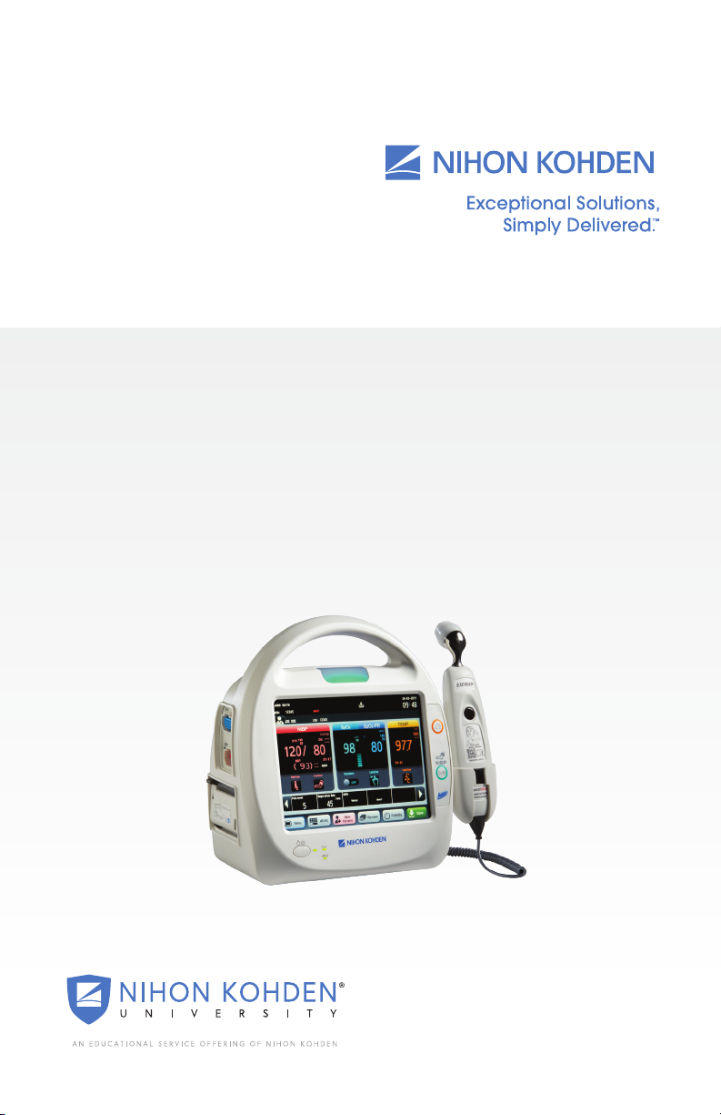
Left View
6
1 SpO2 socket
. 7/25/2019 11:40 AM
Comment [6]: Note for Diagram
label SP02 socket – the 2 is written
inconsistently throughout this
document. In the table below as SpO2
3
1 SpO Socket
2 Debrillation-proof part symbol
3 NIBP socket
4 Recorder holder
Item Description
1
SpO2 socket Connects to specied SpO connection cord.
5 Caution label
Defibrilliation-proof
2
part symbol
3 NIBP socket
4
Recorder holder
5
Caution label
Refer to Operator Manual for details.
Part symbol.
Connects to the air hose.
For mounting a recorder.
us.nihonkohden.com
Page 8
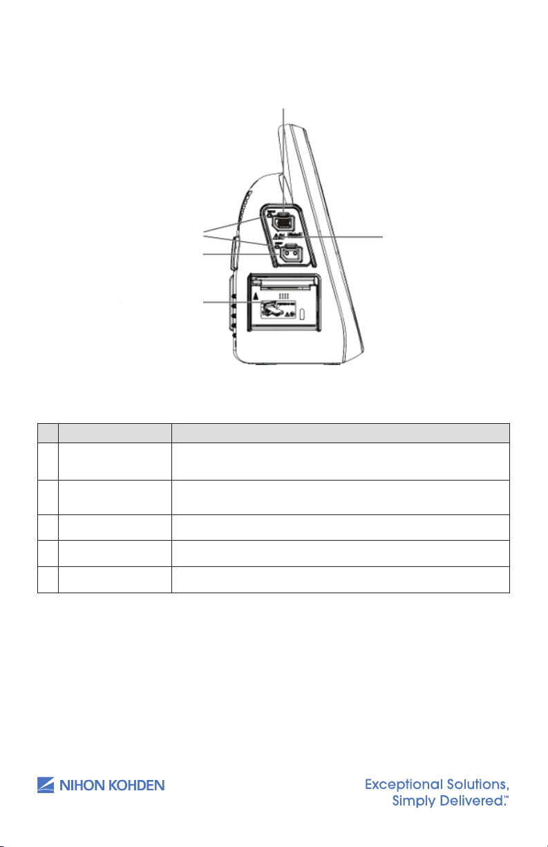
Right View
7
7
Description
For mounting a battery pack.
4
1 Battery pack holder
Item Description
1 Battery pack holder
For mounting a battery pack.
Top View (With Wireless LAN Module)
1 WLAN power lamp
3 WLAN lamp
2 WLAN LINK lamp
Item Description
1 WLAN Power lamp
2 WLAN LINK lamp
3 WLAN lamp
us.nihonkohden.com
Lights when the WLAN power is turned on.
Lights when the WLAN power is ready.
Lights when WLAN is connected.
Page 9
8
Item
Description
Press and hold for more than 5 seconds to restore to the
default setting. Press and hold for 1 second and less to
reset WLAN.
For mounting a temperature probe.
For serial communication.
Connects to monitor network system by a network
cable.
For USB memory or barcode reader or keyboard.
For the AC power cord.
For a potential equalization terminal conductor.
. 7/25/2019 10:56 AM
Comment [8]: Not capitalized in
diagram. Deliberate?
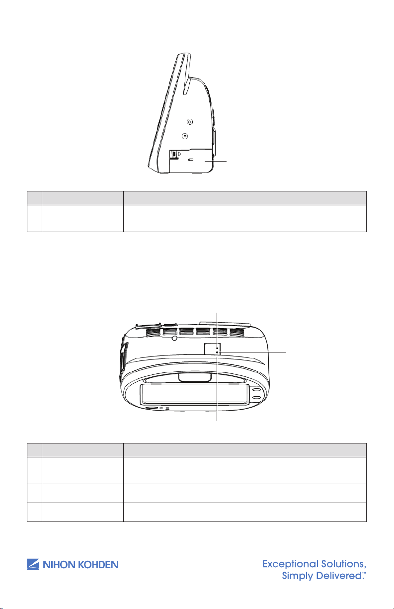
Rear View
1 WLAN setup button
2 Temperature socket
1 WLAN setup button
3 Serial socket
4 Network socket
Item Description
5
7 Potential equalization terminal
6 AC power source socket
5 USB sockets
Press and hold for more than 5 seconds to restore to the default
setting. Press and hold for 1 second and less to reset WLAN.
2 Temperature socket
3
Serial socket For serial communication.
4
Network socket Connects to monitor network system by a network cable.
5
USB sockets For USB memory or barcode reader or keyboard.
AC power source
6
socket
Potential
7
equalization terminal
us.nihonkohden.com
For mounting a temperature probe.
For the AC power cord.
For a potential equalization terminal conductor.
Page 10
Admitting a New Patient and Inputting
9
•
Use a barcode reader and scan the barcode of the patient;
•
Press the [New Patient] key on the main screen when it is customized
to the screen;
•
Press the [Menu] key on the main screen to open the Menu window.
Press the [Patient List] key from the Menu window and then press the
[New Patient] key to admit a new patient.
. 7/25/2019 11:47 AM
Comment [9]: I haven’t heard this
expression before and I’m not entirely
sure what you mean. Do you mean
when the key is highlighted or
something similar?
. 7/25/2019 11:07 AM
Comment [10]: Comma not
standardly used in this kind of
structure.
Patient Information
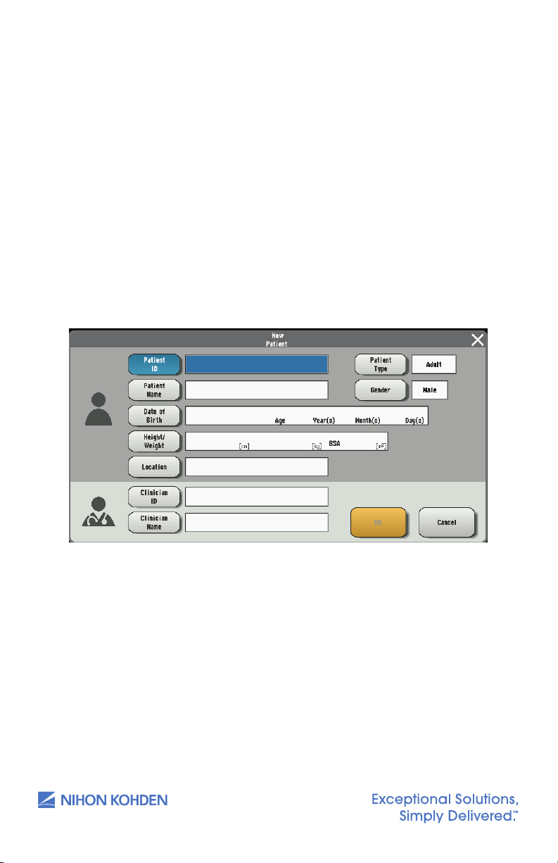
Open the NEW PATIENT window to add a new patient. There are three
methods to open the NEW PATIENT window:
• Use a barcode reader and scan the barcode of the patient;
• Press the NEW PATIENT key on the main screen when it is customized
to the screen;
• Press the MENU key on the main screen to open the MENU window.
Press the PATIENT LIST key from the MENU window and then press
the NEW PATIENT key to admit a new patient.
6
us.nihonkohden.com
Page 11

Inputting the PATIENT ID
10
Touch the [Patient ID] key on the New Patient window and then
enter the patient ID by using the touch keys.
Or, on the Home screen, scan the patient ID by using the bar code
scanner, the Patient ID will be entered automatically.
Up to 16 characters can be entered.
1. Touch the PATIENT ID key on the NEW PATIENT window and then
enter the patient ID by using the touch keys.
Or, on the Home screen, scan the patient ID by using the bar code
scanner, the Patient ID will be entered automatically.
Up to 16 characters can be entered.
2. Touch the ENT key to conrm the input and then return to the NEW
PATIENT window.
7
us.nihonkohden.com
Page 12
Inputting the PATIENT NAME
11
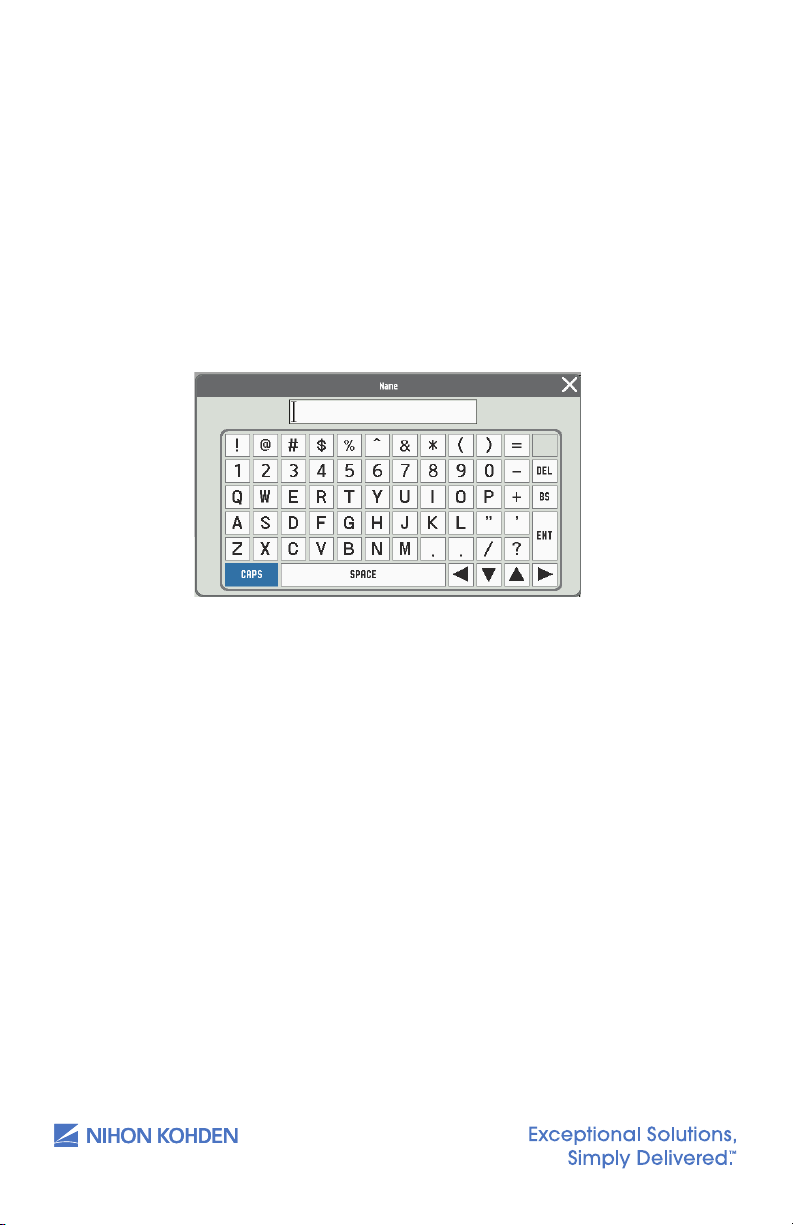
1. Touch the PATIENT NAME key on the NEW PATIENT window and then
enter the patient name in the pop-up window.
OR, on the Home screen, scan the patient name by using the bar
code scanner; the patient name will be input automatically (if
connected to network ADT server).
Up to 15 characters can be entered.
8
2. Touch the ENT key to conrm the input and then return to the NEW
PATIENT window.
us.nihonkohden.com
Page 13

Inputting the Date of Birth
11
1. Touch the DATE OF BIRTH key on the NEW PATIENT window and then
input the date of birth.
2. Touch the SET key to save your input and return to the NEW PATIENT
window or PATIENT INFO window by touching the key.
NOTE: If you close the BIRTH DATE/AGE window without touching
the ENT key, the date of birth will not be changed.
9
us.nihonkohden.com
Page 14
Inputting the Height and Weight
12
12
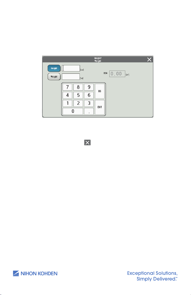
1. Touch the HEIGHT or WEIGHT key on the NEW PATIENT window and
then input the height and weight separately.
10
2. Touch the ENT key to save your input and return to the PATIENT INFO
window by touching the
NOTE: If you close the HEIGHT/WEIGHT window without touching
the ENT key, the entered height and weight cannot be saved.
ke y.
us.nihonkohden.com
Page 15
Managing Patient Information
13
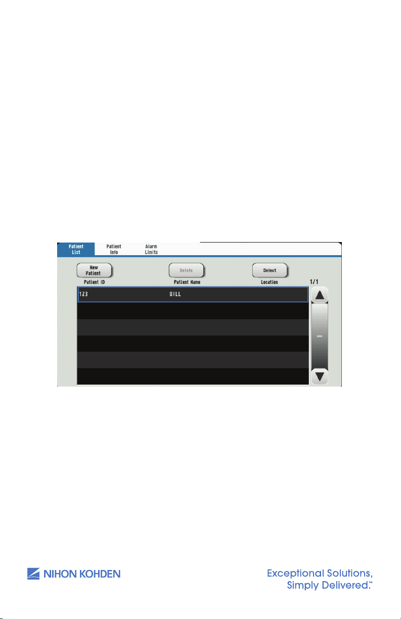
1. Use the keys on the PATIENT WINDOW to add, delete, and change
the patient information.
2. Touch the PATIENT LIST key on the MENU window to display the
PATIENT LISTwindow.
3. To delete a patient’s information, select the patient information
and touch the DELETE key.
NOTE: A currently admitted patient cannot be deleted.
4. To change a patient’s information, select the patient information
and touch the SELECT key to open the NEW PATIENT window.
11
us.nihonkohden.com
Page 16
Discharging a Patient
14
. 7/25/2019 11:23 AM
Comment [11]: ‘in default’ means
to be guilty of not repaying a loan.
14
. 7/25/2019 11:23 AM
Comment [11]: ‘in default’ means
to be guilty of not repaying a loan.
In Spot Mode
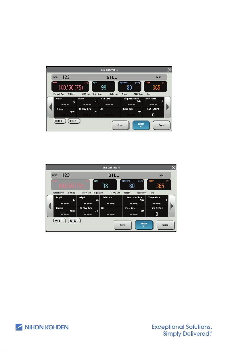
1. Touch the SAVE key on the Home screen. Open the SAVE window.
All the parameters are selected as default.
2. Touch the items to unselect parameters. The unselected item
turns gray.
12
3. Touch the SAVE* or SAVE & SEND* key to send the selected
parameter to EMR and save to le. Aer the data is sent
successfully, the patient will be discharged automatically, and the
monitor is available for the next patient.
In spot mode, a patient will be discharged automatically aer his
or her data is saved. To readmit the patient, touch the PATIENT LIST
key to select the patient.
us.nihonkohden.com
Page 17

In Continuous Mode
15
Touch the [Menu] key � [Patient Info] key.
15
Touch the [Menu] key � [Patient Info] key.
Touch the [Quit Patient] key on the bottom right of the window. The Quit
Patient window appears.
13
1. Touch the MENU key
2. Touch the QUIT PATIENT key on the bottom right of the window. The
QUIT PATIENT window appears.
W
PATIENT INFO key.
3. Touch the YES key to quit monitoring. The data is cleared from the
Home screen.
Or, touch the QUIT PATIENT key on the Home screen when it is
customized to the Home screen.
us.nihonkohden.com
Page 18

Saving and Sending Patient Information
16
Spotcheck mode: Black background
Continuous mode: Blue background
. 7/25/2019 11:27 AM
Comment [13]: I’m not entirely
sure what you mean by this. Perhaps
you mean ‘locally’?
In Spot Mode
1. Touch the SAVE key aer admitting a patient. Open SAVE window.
2. All the parameters are selected as default. Touch to unselect
parameters.
3. Touch the SAVE key to save the selected data locally.
Or, touch the SAVE & SEND key to save the selected data in local
and send to the external system.
When the SAVE & SEND key is touched, if the data is sent to the
external system, a corresponding visual and auditory message will
appear, and the record of the data will be saved in the SPOT TABLE
in dim gray.
Alternatively, a corresponding visual and auditory message indicating
failure will appear, and a conrmation window will be displayed.
Touch the SAVE & SEND key in the conrmation window to resend. If
the data fails to be sent again, a timeout message will appear, and
the record of the data will be saved in the SPOT TABLE in black.
14
NOTE: When the memory becomes full, the oldest le is deleted to create
a new le.
In Continuous Mode
Touch the SAVE key to save the data. The data will be saved in the ID of
the patient currently logged in. If there is no patient logged in, the data
will be saved in an unused ID assigned by the system.
Display
NOTE: The background color indicates the current mode.
Spot mode: Black background Continuous mode: Blue background
us.nihonkohden.com
Page 19
Basic Operation
17
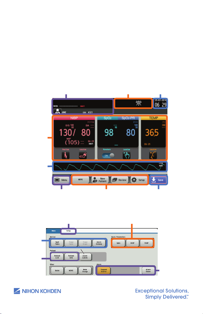
Indication area
Clock
17
Menu
Customized keys
[Save] key. Touch this key
to save the measurement
data.
Indication area
Clock
Alarm limits
Setup window
Parameters window
The monitor can be operated by touch keys on the screen. Touch one
of the operation keys or function keys on the screen to perform an
operation, change a setting, or open/close a window. When a key is
touched, there is a beep sound.
There are two monitoring modes within the monitor: spot mode and
continuous mode. Change the mode by touching the MODE CHANGE
key on the MENU window.
Clinician and Patient Information Indication area Clock
Measuring
data
Measuring
data display
area
15
MENU Key. Touch this to
open the menu screen.
Menu
Access
to review
screens
PATIENT
window
us.nihonkohden.com
Customized keys
SETUP window PARAMETERS window
SAVE Key. Touch
this key to save the
measurement data.
ALARM
window
Page 20

Modified Early Warning Score
18
. 7/25/2019 11:48 AM
Comment [14]: Here also, I’m not
sure what you mean exactly.
The modied early warning score (MEWS) is a tool to quickly determine
the degree of illness of a patient. It is based on vital signs such as SpO,
NIBP, temperature, respiratory rate, etc. and can be customized to your
facility’s standards or protocols by your system administrator.
To Get a Modified Early Warning Score (MEWS)
1. Display the MENU window.
2. Touch the MEWS key on the MENU window to display the MEWS
window.
Or, touch the MEWS key on the Home screen when it is customized
to the Home screen.
3. Touch the MEWS key to close the MEWS window and return to the
Home screen.
16
us.nihonkohden.com
Page 21

Monitoring Parameters
19
1
Make any necessary changes to the NIBP settings by touching the NIBP
parameter, or touch [Menu] � [NIBP].
2
Touch the NIBP Start/Stop key on the right of the monitor to start
measuring.
3
To stop the measurement, touch the NIBP Start/Stop key again. The cuff
will deflate.
NIBP Monitoring
Cu selection should be based on the size of the patient’s arm. The
American Heart Association recommends that the cu width be 40% of
the circumference of the upper arm. Inappropriate cu sizes can result in
inaccurate NIBP results.
Starting and Stopping NIBP Measurement
1. Make any necessary changes to the NIBP settings by touching the
NIBP parameter, or touch MENU
2. Touch the NIBP START/STOP key on the right of the monitor to start
measuring.
3. To stop the measurement, touch the NIBP START/STOP key again.
The cu will deate.
Changing NIBP Settings
W NIBP.
17
Change the settings on the NIBP window.
The following settings can be changed by touching the appropriate data
eld for monitoring NIBP.
• NIBP alarm limits
• MEASUREMENT INTERVAL (only available in continuous mode)
• INITIAL CUFF PRESSURE TYPE
• INITIAL CUFF PRESSURE
• INFLATE MODE (CAN ONLY BE USED WITH NIHON KOHDEN
SPECIFIED CUFFS)
us.nihonkohden.com
Page 22

NIBP Interval Settings
20
. 7/25/2019 4:38 PM
Comment [15]: I’m not sure why
this is written in all caps? Not
consistent with other headings of
same level.
. 7/25/2019 11:55 AM
Comment [16]: Have changed for
consistency with above.
. 7/25/2019 11:55 AM
Comment [17]: Changed for
consistency
Manual Measurement – No interval will be set. NIBP measurement is
obtained by touching the NIBP START/STOP key on the right side of the
monitor.
STAT Measurement – Must be in continuous mode to operate.
Measurements are performed continuously according to the
measurement program set by your administrator. The program is divided
into two stages of interval settings and is limited to 1-minute intervals
during the rst stage.
SIM Mode – Must be in continuous mode to operate. Measurements are
performed continuously according to the measurement program set
by your administrator. The program is divided into two stages of interval
settings and is limited to 2.5-minute intervals during the rst stage.
Interval mode (Must be in continuous mode) – An automatic interval can
be selected to measure NIBP. To change intervals, touch MEASUREMENT
INTERVAL key and select desired NIBP intervals.
Venous Puncture Mode
18
NOTE: Venous puncture mode must be set to ON by your administrator to
use this function and CANNOT be used if an NIBP interval is set.
For aid in inserting a venous line, you can use venous puncture mode to
inate the cu to a target pressure in order to prevent venous backow.
Venous backow causes swelling of the veins and makes it dicult to
insert a venous line.
In venous puncture mode, the cu automatically deates 2 minutes aer
ination in Adult/Child mode or 70 seconds aer ination in Neonate mode.
us.nihonkohden.com
Page 23

Cuff Size
21
Ensure that the correct cu size is used for each patient. Larger cus will
result in lower readings and smaller cus will result in higher readings.
Each cu covers a range of limb sizes.
Select a cu size that is balanced for the limb. When applying the cu,
look at the range marks. Use a cu size that is centered on the range
mark. For example, if the limb is 10.5 cm, using a 6 to 11 cm cu will not
provide the best readings. Instead, use an 8 to 14 cm cu.
• If readings are higher than expected, try a larger cu, and if
readings are lower than expected, try a smaller cu.
• Manual NIBP can be used to check the accuracy of the NIBP
measurement.
19
Cuff Positioning
NIBP cus use an air bladder to occlude the artery during measurement.
To obtain accurate readings, the cu must be correctly positioned over
the artery.
• Each cu should have a mark indicating the position of the artery
in relation to the cu. The mark is usually close to the air hose.
Ensure that the mark is positioned directly over the artery.
Patient Type
Patient type is automatically recognized when the cu is connected
to the monitor. The patient type setting on Nihon Kohden monitors is
controlled by the type of NIBP hose used. Both Adult/Child and Neonatal
hoses are available.
us.nihonkohden.com
Page 24

Measuring Mode
22
22
There are two measuring modes for the monitor: deflation mode and
inflation mode. The factory setting is deflation mode, and inflation
mode is set to OFF.
NOTE: Inflation mode will only work with Nihon Kohden approved cus.
Deflation Mode
When the pressure deates slowly,
the change of artery pulse wave
is regarded as the change of cu
pressure, and blood pressure is
calculated by the amplitude pattern.
Inflation Mode
20
When inating the cu gradually,
the change of artery pulse wave
is regarded as the change of cu
pressure, and blood pressure is
calculated by the amplitude pattern.
In this mode, cu ination is lower
than in deation mode and can be
measured in a short time.
us.nihonkohden.com
Page 25

SpO2 Monitoring
The Nihon Kohden Vital Signs Monitor uses an SpO cable, which accepts
reusable or disposable probes. The monitor comes with three options for
pulse oximetry: Nihon Kohden, Nellcor, and Masimo technology. Refer to
the Operator’s Manual for specic technology dierences.
Connect the appropriate SpO probe to the monitor cable, attach the
probe to the patient, and begin monitoring.
Starting SpO2 Measurement
When the preparation is done properly, the SpO value and pulse
waveform appear on the screen.
NOTE: Settings may be dierent depending on the SpO technology
utilized on your Nihon Kohden monitor.
21
us.nihonkohden.com
Page 26

Changing SpO2 Settings
23
Change the settings on the SpO window.
The following settings can be changed for SpO monitoring:
• SpO and pulse rate alarm limits
• Pulse waveform sensitivity
• Sync pitch
• Response mode
22
• Sensitivity mode
• Average Time (Masimo Only)
• Fast Sat (Masimo Only)
The SpO pulse waveform sweep speed is the speed set for <Sweep
Speed> on the DISPLAY/SOUND window.
us.nihonkohden.com
Page 27

Temperature Monitoring
24
1
Slide across forehead.
Place probe flush on center of forehead and
depress button. Keeping button depressed,
slowly slide probe mid-line across forehead to
hair line.
2
Slide behind ear. (Skip this step if the patient
is an infant.)
Press and hold button, lift probe from
forehead, touch behind ear halfway down
mastoid process and slide down to soft
depression behind earlobe.
3
Release button and review results.
. 7/25/2019 12:08 PM
Comment [20]: If you wish to use a
‘note-writing’ mode where the article
‘the’ is omitted, it must be done
consistently.
Taking a Temperature
The SVM-7200 Vital Signs Monitor comes with an Exergen Temporal
Scanner or a Covidien Sensor in a blue or red casing for temperature
monitoring. Please review the Operator’s Manual for further instructions.
1. Ensure the appropriate probe casing is attached if using the
Covidien Sensor (blue for oral/axillary and red for rectal).
2. When the temperature scanner/sensor is withdrawn, the
thermometer turns on automatically.
3. Proceed to take the patient’s temperature as explained below.
Exergen Temporal Scanner
1. Slide across forehead.
Place probe ush on center of forehead and
depress button. Keeping button depressed, slowly
slide probe mid-line across forehead to hair line.
2. Slide behind ear. (Skip this step if the patient is
an infant.)
Press and hold button, li probe from forehead,
touch behind ear halfway down mastoid process
and slide down to so depression behind earlobe.
23
3. Release button and review results.
us.nihonkohden.com
Page 28

Covidien Sensor
25
. 7/25/2019 1:17 PM
Comment [21]: Would ‘lid’ work
here? The repetition of cover is a little
confusing to read.
25
Peel off probe cover box cover in the direction of the arrow on the
box.
Insert a box of probe covers into the top of the temperature sensor
casing.
NOTE: A blue casing is indicative of oral and axillary use, and a red
casing is indicative of rectal use. Insert the appropriate colored
casing before each use. Please see the Operator’s Manual for casing
removal.
Withdraw the probe from the probe well. The thermometer is
automatically open.
. 7/25/2019 1:17 PM
Comment [21]: Would ‘lid’ work
here? The repetition of cover is a little
confusing to read.
Use only Filac 3000 AD/ADA Electronic Thermometer probe covers
with this device. Use of any other probe cover will result in erroneous
temperature readings.
Applying Probe Covers
1. Peel o probe cover box cover in the direction of the arrow on
the box.
2. Insert a box of probe covers into the top of the temperature
sensor casing.
NOTE: A blue casing is indicative of oral and axillary use, and a red
casing is indicative of rectal use. Insert the appropriate colored
casing before each use. Please see the Operator’s Manual for
casing removal.
3. Withdraw the probe from the probe well. The thermometer is
automatically open.
NOTE: The icon
screen, reminding the user to apply or
remove a probe cover.
4. Insert the probe end into a cover in the box. Push the handle rmly
until you feel the cover “snap” into place.
5. Take appropriate temperature measurement (oral, axillary, or rectal).
NOTE:
• Aer measurement, push the top button to eject the used
cover into a bio-waste container.
• Probe covers are consumables. Remove, discard, and replace
boxes when empty.
is ashing on the display
24
us.nihonkohden.com
Page 29

Setting the Modes of Temperature Measurement
Open the TEMP window and touch MEAS MODE to change the
temperature measurement mode to Quick, Standard, or Direct
Four temperature measurement modes are available: Standard mode,
Direct mode, Quick mode, and Cold mode.
Standard Mode
1. The thermometer normally operates in Predictive mode for
accurate temperature measurement. In certain cases, such as with
a hypothermic patient, the thermometer will automatically shi to
Direct (slow) mode and will then act as a temperature monitor.
Direct Mode (Oral & Axillary & Rectal)
1. The thermometer can be set to operate exclusively in Direct mode
(disable Predictive mode).
2. In Direct mode the device may require up to 60 seconds to reach
equilibrium and display patient temperature.
25
Quick Mode (Oral Only)
1. Quick mode is provided for more rapid, time consistent, oral
temperature predictions. This mode is indicated by a rabbit icon on
the display. In this mode, a temperature measurement prediction is
provided in approximately 3.5–4 seconds.
2. Quick mode is not available with Axillary or Rectal Body Sites, with
Cold mode, or when in Direct mode.
us.nihonkohden.com
Page 30
Cold Mode
27
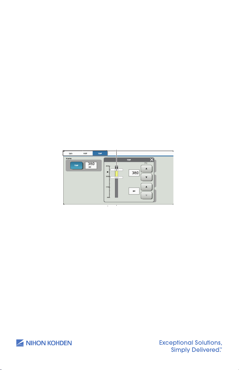
Upper limit slider
Upper limit
out of surgery.
2
Cold mode is not available with Quick mode or when in Direct mode.
Setting Temperature Alarm Limits
Touch the [TEMP] key on the Menu screen to open the temperature window
and then set the upper and lower alarm limits.
Touch the desired tab to change the
Setting bar
Lower limit
Lower limit slider
Selected
1. Cold mode is provided for use in applications where body
temperatures may be lower than normal, such as in patients
recently out of surgery.
2. Cold mode is not available with Quick mode or when in
Direct mode.
Setting Temperature Alarm Limits
Touch the TEMP key on the MENU window to open the TEMPERATURE
window and then set the upper and lower alarm limits.
displayed parameters
parameter
Current measured value
26
us.nihonkohden.com
Page 31

Alarm Types and Levels
There are two types of alarms – the vital signs alarm and technical alarm –
and three alarm levels – crisis, warning, and advisory.
The monitor can indicate alarms both visually and audibly:
• Alarm sound
• Alarm message on the screen
• Alarm indicator: the alarm indicator indicates three alarm levels.
27
Alarm Level Alarm Sound
CRISIS NK1 (Continuous
WARNING
ADVISORY NK1 and NK2 (Single
pip sound), NK2
(Continuous ping
sound) or IEC
standard (ceg-gC)
NK1 (Continuous bing
bong sound), NK2
(Continuous ding
ding sound) or IEC
standard (ceg)
beep every 20
seconds) or IEC
standard (Single beep
every 20 seconds)
Alarm Display
on the Screen
Highlighted red
message
Highlighted
yellow or
orange
message
Highlighted
yellow or blue
message
Alarm
Indicator LED Alarm Recording
Blinking red
Recorded at alarm
Blinking yellow
Lights in yellow
or blue
occurrence when
alarm recording on
the Record window
is set to ON.
us.nihonkohden.com
Page 32

Alarm Message Display and Icons
28
Alarm Types and Levels
There are two types of alarms – the vital signs alarm and technical alarm – and
three alarm levels – crisis, warning, and advisory.
The monitor can indicate alarms both visually and audibly:
• Alarm sound
• Alarm message on the screen
• Alarm indicator: the alarm indicator indicates three alarm levels.
CRISIS: Red blinking; WARNING: Yellow blinking; ADVISORY: Yellow or blue
Alarm
Level
Alarm Sound
Alarm Display
on the Screen
Alarm Indicator
LED
Alarm
Recording
NK1 (Continuous
pip sound), NK2
(Continuous ping
sound) or IEC
standard (ceg-
gC)
Highlighted red
message
Blinking red
Recorded at
alarm occurrence
when alarm
recording on the
Record window is
set to ON.
NK1 (Continuous
bing bong sound),
NK2 (Continuous
ding ding sound)
or IEC standard
(ceg)
Highlighted yellow
or orange
message
Blinking yellow
NK1 and NK2
(Single beep
every 20 seconds)
or IEC standard
(Single beep
every 20 seconds)
Highlighted yellow
or blue message
Lights in yellow or
blue
Alarm Message Display and Icons
When two or more alarms occur at the same time, the messages are displayed
alternately in the alarm message
Alarm is silenced by touching the Silence Alarm key on the monitor.
Remaining minutes appears.
Alarms are suspended (paused) for a certain period.
Alarms are suspended infinitely or vital sign alarm limit is set to OFF.
Alarms are reset.
Alarm message display area
29
Guide symbol
When two or more alarms occur at the same time, the messages are
displayed alternately in the alarm message display area.
display area.
Guide Menu
When a technical alarm occurs during monitoring, the guide symbol
appears at the top of the screen. Touch the guide symbol to open the
guide menu for that alarm.
28
us.nihonkohden.com
Page 33

Silencing and Suspending Alarms
29
Guide symbol
Suspend all alarms for 1, 2, or 3 minutes by touching the [Suspend
Alarms] key; for example, for probe replacement, etc. The time allowed
will be set by the administrator.
• Alarm function resumes when the suspend alarm time elapses
or the [Suspend Alarms] key is touched.
30
•
Suspend all alarms indefinitely by touching the [All Alarms Off] key on
the Menu window. Your device may not have this function as it is set by
the administrator.
• Alarm function resumes when the [All Alarms Off] key is touched
Silencing Alarms
When an alarm occurs, you can silence the alarm sound and indications by
touching the SILENCE ALARM key on the monitor. When a vital signs alarm
other than the NIBP alarm is silenced, the alarm resumes aer the alarm
silence ends. When several alarms occur together and the SILENCE ALARM
key is touched, all alarms are silenced and technical alarms are reset.
When the vital signs monitor is connected to a central monitor network, all
alarms other than the NIBP alarm are temporarily silenced by touching the
SILENCE ALARM key on the central monitor. Refer to the central monitor
Operator’s Manual for details.
Suspending Alarms
All alarms can be suspended before they occur. During alarm suspension,
all alarms are turned OFF for the specied period set by the administrator.
This monitor has three types of alarm suspension:
29
• Suspend all alarms for 1, 2, or 3 minutes by touching the SUSPEND
ALARMS key; for example, for probe replacement, etc. The time
allowed will be set by the administrator.
• Alarm function resumes when the suspend alarm time elapses or
the SUSPEND ALARMS key is touched.
• Suspend all alarms indenitely by touching the ALL ALARMS OFF key
on the MENU window. Your device may not have this function as it
is set by the administrator.
• Alarm function resumes when the ALL ALARMS OFF key is touched.
us.nihonkohden.com
Page 34

• Suspend all alarms indenitely by touching the SUSPEND
30
•
Suspend all alarms indefinitely by touching the [All Alarms Off] key on
the Menu window. Your device may not have this function as it is set by
the administrator.
• Alarm function resumes when the [All Alarms Off] key is touched
•
Suspend all alarms indefinitely by touching the [Suspend Monitoring]
key. For example, suspend alarms while the patient is being examined.
• When the [Suspend Monitoring] key is touched, all alarms and
NIBP measurements are suspended.
• Alarm function resumes when the [Suspend Monitoring] key or
[Suspend Alarms] key is touched or the desired conditions are
met.
30
• Alarm function resumes when the [All Alarms Off] key is touched
• When the [Suspend Monitoring] key is touched, all alarms and
NIBP measurements are suspended.
• Alarm function resumes when the [Suspend Monitoring] key or
[Suspend Alarms] key is touched or the desired conditions are
met.
Alarm off keys
MONITORING key. For example, suspend alarms while the patient is
being examined.
• When the SUSPEND MONITORING key is touched, all alarms and
NIBP measurements are suspended.
• Alarm function resumes when the SUSPEND MONITORING key or
SUSPEND ALARMS key is touched or the desired conditions are met.
30
Alarm OFF Keys on the MENU Window
The SUSPEND ALARMS, ALL ALARMS OFF, and SUSPEND MONITORING keys
are toggle keys. Touch once to activate and touch again to cancel.
us.nihonkohden.com
Page 35

Changing Parameter Alarm Limits
31
Upper limit
Upper limit slider
Change upper or lower alarm limits for each parameter individually
from each parameter window by touching [Menu] and the desired
parameter key, such as [Temp] in the below illustration.
Touch desired tab to change the
Setting bar
Lower limit slider
Lower limit
Current measured value
There are three ways to change vital signs upper/lower alarm limits.
Review the Operator’s Manual for further details.
• Change upper or lower alarm limits for each parameter individually
from each parameter window by touching MENU and the desired
parameter key, such as TEMP in the below illustration.
displayed parameters
Selected
parameter
• Change upper or lower alarm limits for each parameter individually
from the menu. Touch the MENU key, followed by the ALARM LIMITS
key. Adjust alarm limits as desired.
31
us.nihonkohden.com
Page 36

• Set all alarm limits to the alarm master settings from the menu.
31
Upper limit
Upper limit slider
Changing Parameter Alarm Limits
There are three ways to change vital signs upper/lower alarm limits. Review
the Operator’s Manual for further details.
•
Change upper or lower alarm limits for each parameter individually
from each parameter window by touching [Menu] and the desired
parameter key, such as [Temp] in the below illustration.
•
Change upper or lower alarm limits for each parameter individually
from the menu. Touch the [Menu] key, followed by the [Alarm limits]
key. Adjust alarm limits as desired.
•
Set all alarm limits to the alarm master settings from the menu. Touch the
[Menu] key, followed by the [Alarm limits] key. Touch the [Alarm Master]
key. The “Apply settings from master?” message appears. Select desired
response.
Touch desired tab to change the
displayed parameters
Setting bar
Lower limit slider
Lower limit
Current measured value
Selected
parameter
Selected parameter
Upper limit slider
Upper limit
Lower limit
Lower limit slider
Current measured value
Setting bar
Alarm Master
Touch the MENU key, followed by the ALARM LIMITS key. Touch the
ALARM MASTER key. The “APPLY SETTINGS FROM MASTER?” message
appears. Select desired response.
ALARM MASTER
key
key
32
us.nihonkohden.com
Page 37

Review Windows
32
Review Windows
You can review saved data on the following review windows.
In spot mode, the Spot Table window and Alarm History window are available.
In continuous mode, the Spot Table window, Trend Table window, Trend
Graph window, and Alarm History window are available.
NOTE: The oldest file is deleted when the maximum number of files has been saved.
Display Review Windows
Touch the [Menu] key on the screen to display the available review windows.
The review windows that are not available will be grayed out.
Review window
Display
Storage
Spot Table
window
Displays vital signs data
Up to 10,000 files of vital
signs data can be saved
Trend Table
window
Displays vital signs data
Up to 10,000 files of vital
signs data can be saved
Trend Graph
window
Displays vital signs trend
graphs
Up to 10,000 files of vital
signs graphs can be saved
Alarm History
window
Displays a table of
technical alarms
Up to 10,000 files of alarm
history data can be saved
Review
. 7/25/2019 1:33 PM
Comment [22]: Consider using a
comma or thin space after the 10 to
make reading easier:
10,000 or 10 000
Thin space can be entered by
selecting the ¼ em space from insert
Special Characters in Word.
You can review saved data on the following review windows.
In spot mode, the SPOT TABLE window and ALARM HISTORY window are
available.
In continuous mode, the SPOT TABLE window, TREND TABLE window,
TREND GRAPH window, and ALARM HISTORY window are available.
Review Window Display Storage
SPOT TABLE window Displays vital signs data Up to 10,000 les of vital signs data can
TREND TABLE window Displays vital signs data Up to 10,000 les of vital signs data can
TREND GRAPH window Displays vital signs trend
ALARM HISTORY
window
graphs
Displays a table of technical
alarms
NOTE: The oldest le is deleted when the maximum number of les has
been saved.
DISPLAY REVIEW Windows
Touch the MENU key on the screen to display the available REVIEW
be saved
be saved
Up to 10,000 les of vital signs graphs
can be saved
Up to 10,000 les of alarm history data
can be saved
windows. The REVIEW windows that are not available will be grayed out.
REVIEW
windows
windows
33
us.nihonkohden.com
Page 38

SPOT TABLE Window
33
1
2
3 4 5
6
When NIBP or TEMP measurement is completed or when SAVE is pressed,
the measuring values may be displayed on the SPOT TABLE window.
1. Patient information filter area
Tap the dialog box to choose the patient name or ID. Tap ALL to
display all data.
34
2. Send key
3. Delete key
4. Details icon
5. Record area
6. Check box
us.nihonkohden.com
Tap SEND to send the record you choose.
Tap DELETE to delete the record you choose.
Tap to display SPOT DATA DETAILS window.
The records which have been sent are in gray. The records which
have not been sent are in black.
Tap a check box to choose the record you need.
Page 39

TREND TABLE Window (in continuous mode only)
34
1
2
3
1. Patient information filter area
Tap the dialog box to choose the patient name or ID. Tap ALL to
display all data.
2. Time interval filter area
Tap the dialog box to choose 1 min, 5 min, 10 min, 15 min, 30 min,
or 1 h.
35
3. Record area
us.nihonkohden.com
The records which have been sent are in gray. The records which
have not been sent are in black.
Page 40

TREND GRAPH Window (in continuous mode only)
34
Trend Table Window (in continuous mode only)
1
Patient information filter area
Tap the dialog box to choose the patient name or ID. Tap [ALL] to
display all data.
2
Time interval filter area
Tap the dialog box to choose 1 min, 5 min, 10 min, 15 min, 30 min, or
1 h.
3
Record area
The records which have been sent are in gray. The records which
have not been sent are in black.
Trend Graph Window (in continuous mode only)
1
2
3
Cursor
Filter and
Setup
Time Bar
Scale
Set Up Scale
Record
. 7/25/2019 1:40 PM
Comment [23]: The spelling is set
up when used as a verb, and setup
35
Alarm History Window
Display review windows
Date and
time of file
Selected
Alarm history data
Scroll to
Event Bar
ALARM HISTORY Window
creation
Param eter
36
parameters
Graph
Selection
file
display
additional
files
us.nihonkohden.com
Page 41

Cleaning and Disinfecting
Please consult the Operator’s Manual or the Cleaning and Disinfecting
Guide for a complete list of approved cleaning and disinfecting agents.
*The use of any other disinfectant solutions may cause damage to the
equipment and may void the product warranty.
37
us.nihonkohden.com
Page 42

Screen Messages and Troubleshooting
Please refer to the Operator’s Manual for further troubleshooting
Screen Message Parameter Possible Cause/Criteria Action
[– – –] Alarm All
*
Air Leak NIBP The cu pressure does
*
parameters
Alarm Silenced All
-
Alarms Suspended/
-
Suspend Monitoring
All Alarms O All
-
Battery Weak System Battery pack is fully
*
parameters
All
parameters
parameters
Alarm occurred for the
[– – –] (parameter).
not change aer
ination even aer a
certain period of time.
The cu or air hose is
damaged.
The SILENCE ALARMS
key was touched to
silence the alarm.
The SUSPEND
MONITORING key was
touched.
The ALL ALARMS OFF
key is touched to
suspend alarm function.
discharged.
Take appropriate action
depending on the alarm
level. (Displaying the Home
screen may display the alarm
in detail.)
Connect the cu to the air
hose properly.
Connect the air hose to the
socket properly.
Replace the cu or air hose
with a new one.
• When the alarm cause
is resolved, the alarm is
cleared.
• When the SILENCE ALARMS
key is touched during
alarm silence, all alarms
are resumed.
• All alarms resume when
the SUSPEND MONITORING
key is touched again
during alarm suspension.
• Alarm suspension is
canceled when monitoring
starts.
To resume alarm function,
touch the ALL ALARMS OFF
ke y.
Switch to AC power and
charge the battery pack.
38
us.nihonkohden.com
Page 43

Screen Message Parameter Possible Cause/Criteria Action
Cannot Detect
*
Pulse
Check Probe SpO The probe cable is
*
Check Probe Site SpO The probe is not
*
Check Sensor TEMP The probe is
*
NIBP The patient’s pulse
wave is small.
The cu is not wrapped
around the patient
correctly.
SpO Poor blood circulation
for measuring the SpO
value.
The probe is attached
too tightly and is
obstructing blood
circulation.
The probe is not
attached to the patient
properly.
One of the following
messages is displayed
for 30 seconds.
• LIGHT INTERFERENCE
• CHECK PROBE SITE
• DETECTING PULSE
disconnected from the
SpO connection cord.
The probe is not
attached to the patient.
properly.
The probe is broken or
short-circuited.
attached at the
appropriate site.
disconnected from the
TEMP socket.
The probe is damaged. Replace the probe with a
The measured value is
outside the measuring
range
Measure by palpation or
the invasive blood pressure
method.
Wrap the cu around the arm
of the patient properly.
Check the patient’s condition
and probe attachment, or
change the attachment site.
Reattach the probe.
Attach the probe to the
patient properly.
Refer to each screen message
section and remove the cause
of the alarm or message.
Connect the probe cable to
the SpO connection cord.
If SpO monitoring is not
necessary, touch the SILENCE
ALARMS key.
Attach the probe to the
patient properly.
Replace the probe with a
new one. If the message still
appears, replace the SpO
connection cord with a
new one.
Attach the probe to a site 6
to 14 mm thick.
Connect the probe to the
TEMP socket.
new one.
Check the probe attachment
site.
39
us.nihonkohden.com
Page 44

Screen Message Parameter Possible Cause/Criteria Action
Communication
*
Loss
Connector O SpO The probe cable is
*
Cu Occlusion NIBP The cu pressure does
*
Detecting Pulse SpO The SpO value cannot
-
Ination Time
-
Passed
Insert Rec Paper Recording No recording paper. Load the recording paper.
-
Light Interference SpO Too much light on the
*
System Network is not
connected.
disconnected from the
SpO connection cord.
The SpO connection
cord is disconnected
from the SpO
socket.
not decrease aer
measurement has
completed.
be obtained because
the waveform is unstable.
Poor blood circulation
for measuring SpO.
The probe is secured
too tightly and is
obstructing blood
circulation.
The probe is
disconnected from the
SpO connection cord.
The nger probe is not
attached to the patient
properly.
NIBP Venous puncture
cu ination time has
passed.
The recording paper is
not loaded correctly.
probe.
Interference from
surroundings.
The probe attachment
site is not appropriate.
Connect to network.
Connect the probe cable to
the SpO connection cord.
If SpO monitoring is not
necessary, touch the
SILENCE ALARMS key.
Connect the SpO
connection cord properly.
When SpO monitoring is
not necessary, touch the
SILENCE ALARMS key to
silence the alarm.
Check that the air hose is not
bent or squeezed.
Check the probe
attachment.
Check the patient condition
and probe attachment, or
change the attachment site.
Reattach the probe.
Connect the probe to the
SpO connection cord.
Attach the nger probe rmly
to the patient.
Restart venous puncture.
Correctly load the recording
paper.
Remove light or cover the
probe site with a blanket.
Remove the interference.
Attach the probe to an
appropriate site.
40
us.nihonkohden.com
Page 45

Screen Message Parameter Possible Cause/Criteria Action
Low Quality Signal SpO Considerable body
-
Meas Timeout NIBP The measuring time
*
Remeasuring
-
(Remeasurement
is automatically
performed. If
the message still
appears aer
remeasurement,
do the counter
actions.)
Systolic Over NIBP The maximum blood
*
Weak Pulse NIBP The patient’s pulse
-
NIBP The cu is not attached
SpO Poor peripheral
Zeroing NIBP NIBP zero balance
-
movement.
The probe is not
attached to the patient
properly.
exceeded the specied
time due to noise.
to the patient.
Patient moved during
measurement.
Patient’s pulse is too
weak.
The cu is not attached
properly.
The cu size is not
appropriate.
Patient’s pulse and
heart rate is unstable.
pressure exceeded 280
mmHg when using the
adult cu, or 150 mmHg
when using the neonate
cu.
wave is too weak.
The cu is wrapped too
loosely.
The cu size is
inappropriate.
circulation.
The probe is attached
too tightly and is
obstructing the blood
circulation.
adjustment is being
performed.
When the message is
displayed frequently, check
the patient’s condition and,
if necessary, change the
attachment site.
Remove the cause if due to
noise.
Attach the cu to the patient.
Wait for the patient to stop
moving and then measure
again.
Measure by palpation or
the invasive blood pressure
method.
Attach the cu properly.
Check that the cu of the
correct size is used.
Wait for the patient to relax
and stop moving.
Measure by palpation or
invasive blood pressure
measurement.
Measure by palpation or
the invasive blood pressure
method.
Wrap the cu around the arm
properly.
Use the appropriate cu.
Check the patient
condition and change the
attachment site.
Reattach the probe.
Do not touch the cu during
zeroing and wait for the
message to disappear.
41
us.nihonkohden.com
Page 46

Monitoring
Trouble Possible Cause/Criteria Action
The screen is dark. The brightness of the
No sync sound. The sync sound setting is
The monitor only
operates for less
than 5 hours with
a fully charged
battery.
The remaining
battery power on
the battery status
icon on the Home
screen suddenly
decreases.
The actual battery
operation time is
dierent than the
battery status icon.
Battery charging
never ends.
The review data
has been lost.
screen is not appropriate.
The backlight is old. Contact your Nihon Kohden representative.
The monitor is operating
on battery.
turned OFF.
The sync sound volume is
turned down.
Sleep mode is turned on. Sleep mode is turned o when:
The battery pack is old. Replace the battery pack with a fully charged
The battery pack has
been changed.
The battery pack is old.
The battery pack has
been changed.
The battery pack is old.
The battery is inserted
backward.
The monitor power was
turned o by disconnecting
the power cord.
The power cord was
disconnected during
shutdown operation.
The power cord was
disconnected while the
remaining battery power
was too low.
Adjust the setting on the Display/Sound window.
If necessary, set <Power Saving Mode> to OFF
on the System Setup window.
Select ON for <Sync Sound Volume> on the
Display/Sound window.
Adjust the volume setting on the Display/ Sound
window.
• The setting time is up.
• The touch screen is touched.
• The POWER key is pressed.
An alarm occurs (Only when <EXIT SLEEP MODE
ON CRISIS ALARM> on the Sleep Page of the
System Setup window is set to ON.)
Communication with CNS fails. (Network failure).
new one.
Fully charge and discharge the battery pack.
Insert the battery in the right direction.
When the monitor does not shut down
correctly, review data for several minutes
before power o is not saved. Press the POWER
key to turn the power o. Refer to the “Turning
the Monitor O” section.
42
us.nihonkohden.com
Page 47

Network
Trouble Possible Cause/Criteria Action
The monitor
cannot be
connected to
the network.
The monitor
cannot be
connected to
the network
with wireless
communication.
The network cable is not
connected to the monitor
properly.
The network settings are
not correct.
The monitor is not selected
as a monitored bed on
the central monitor or
receiving instrument.
Discontinuity in the network
cable or faulty hub.
Wireless LAN functionality
is turned o on the vital
signs monitor.
The vital signs monitor
is out of range of the
wireless network.
Incorrect wireless LAN
station setting.
Connect the network cable to the monitor
properly.
Set the correct network settings on the Network
window of the System Conguration screen.
Select the monitor as a monitored bed on the
central monitor or receiving instrument.
Replace the network cable or the hub with a
new one.
Set <WLAN> to ON in MENU
WLAN. For details, refer to the “Changing
Settings” section.
Move the vital signs monitor inside the range of
the wireless network.
Save the data in a compatible central monitor.
Setup tab W
W
43
us.nihonkohden.com
Wireless LAN station
failure.
The telemetry gateway
setting is not correct.
Refer to the Operator’s Manual for the wireless
LAN station.
Enter the correct telemetry gateway setting
on the NETWORK window of the SYSTEM
CONFIGURATION screen.
Page 48

Recording
Trouble Possible Cause/Criteria Action
There is no
printing (only
paper feeding).
Waveforms can
be recorded but
the trend and
list recording
cannot.
Printing is faint. Nihon Kohden specied
Dots are missing. The thermal head is dirty.
Recording
suddenly starts
without key
operation.
No paper is
feeding.
Recorder
operates only
some of the time.
The recording paper is
upside down.
Dust in the sensor inside
the recorder.
paper not used.
The thermal head is dirty.
Alarm recording or
periodic recording mode
is set to ON.
The recorder door is open.
Dust may have collected
in the gears.
Dust in the sensor inside
the recorder.
Reload the recording paper into the recorder
correctly.
Clean the surface of the sensor inside the
recorder with a dry cotton swab.
Use the FQW50-2-100 recording paper.
Clean the thermal head with the provided
thermal head cleaning pen.
Clean the thermal head with the provided
thermal head cleaning pen.
Set the alarm recording or periodic recording
to OFF on the Recording window if not needed.
Touch the RECORD key on the screen to stop
recording.
Push the recorder door closed until it clicks.
Contact your Nihon Kohden representative.
Clean the surface of the sensor inside the
recorder with a dry cotton swab.
44
us.nihonkohden.com
Page 49

NIBP
Trouble Possible Cause/Criteria Action
Cu ination pressure
is less than 10 mmHg
or NIBP data display
disappears for a few
seconds.
The cu does not
inate when the NIBP
START/STOP key is
touched.
Abnormal
measurement results
are displayed.
The cu hose is not
connected to the cu socket
properly.
The cu is not wrapped
around the arm or is wrapped
too loosely.
The cu hose or air hose may
be folded or squeezed when
the cu pressure display on the
screen increases quickly, but
the actual cu does not inate.
The cu size is not correct.
The cu is not wrapped around
the arm correctly.
NIBP data is not correct
because of body
movement.
Measurement on the wrong site.
Connect the cu hose to the socket
properly.
Wrap the cu around the upper arm.
Check the cu hose and air hose.
Select the cu which ts the patient’s
limb circumference.
Wrap the cu around the upper arm,
not too tightly or too loosely.
Prevent the patient from moving
during measurement.
Measure NIBP at the correct site.
45
Auto measurement
does not start even
when the time interval
has passed.
The cu suddenly
inates.
Cannot connect cu
to the air hose.
Cannot measure NIBP. Noise interference which
NIBP data on the
screen is dark or “---”
appears.
The time interval for the NIBP
auto measurement is set
incorrectly.
The measurement mode is set
to auto mode.
Vital signs alarm occurred.
Unspecied cu used.
disables the calculation of
blood pressure.
The air hose is bent or squeezed.
The cu has worn out.
The preset time
elapsed from the last
measurement.
Set the correct time interval.
Check the time interval.
Set the NIBP Meas On Vital Alarm
on the Main tab – NIBP page –
Parameter window – System Setup
window to OFF.
Use a cu specied by Nihon Kohden.
Remove the cause.
Remove the cause.
Use a new cu.
When NIBP is measured again, the
data is displayed in normal brightness.
us.nihonkohden.com
Page 50

SpO
2
Trouble Possible Cause/Criteria Action
Unstable SpO value. The probe size is inappropriate.
The probe is attached to the
same limb that is used for NIBP
measurement.
An ESU is used.
Measuring on the venous pulse.
Use the correct size probe.
Attach the probe to the other limb.
Locate the ESU as far as possible from
the probe and wait until the pulse
wave stabilizes.
Cannot measure correctly.
46
SpO value on the
monitor and CO
oximeter do not
match.
No SpO data on the
screen when using
Masimo probe.
No SpO data on the
screen when using
Nihon Kohden probe.
The probe is not attached
properly.
The attachment site is
inappropriate.
The measuring site is not clean.
Too much abnormal
hemoglobin (HbCO,
MetHB, etc.).
Dye (methylene blue or
indocyanine green) is injected
in the blood.
Measuring during CPR.
SpO probe and/or
connection cord other than
specied is used.
The probe is not connected to
the connection cord correctly.
The JL-500P1 or JL-500P2 SpO
adapter is disconnected from
the monitor or probe.
Attach the probe correctly. (The
emitter and detector of the probe
must face each other.)
Attach the probe to a site of 6 mm to
14 mm thick.
If necessary, remove nail polish and
clean the measuring site.
Cannot measure correctly.
Only use the specied SpO probe
and connection cord.
Connect the probe to the connection
cord with the logo labels facing the
same direction.
Connect the SpO adapter to the
monitor and probe.
us.nihonkohden.com
Page 51
Temperature
Exergen Sensor
Trouble Possible Cause/Criteria Action
The temperature value
is not displayed on
the screen.
The temperature value
displayed on the LCD
is dierent from the
one displayed on the
screen of the monitor.
The temperature probe is faulty
or dirty.
Monitor malfunction.
The temperature probe
is disconnected from the
temperature socket.
The temperature probe is
connected to the Network socket.
An incompatible temperature
probe is connected to the
temperature socket.
Noise interference.
Clean the temperature probe.
Contact your Nihon Kohden
representative.
Connect the temperature probe
to the temperature socket
properly.
Connect the temperature probe
to the temperature socket.
Connect a temperature probe
which is compatible with the
bedside monitor. If the problem
is not solved, contact your Nihon
Kohden representative.
Remove the noise source.
Relocate the sensor.
47
Covidien Sensor
Trouble Possible Cause/Criteria Action
Cannot measure
temperature.
Out of Range When the probe is not in contact
Module Error When the Covidien Board has an
Probe Error When the probe has an error, it will
us.nihonkohden.com
When another working
temperature probe is connected to
the input jack but the temperature
value does not appear.
When connecting to the LAN jack,
the temperature value does
not appear.
with the patient, it will be out of
range.
When the temperature value is too
high or low, it will be out of range.
error, it will say "Module Error".
say "Probe Error".
Replace the probe.
Connect the probe to the
temperature input jack.
Conrm the probe is in contact
with the patient.
Conrm the temperature of the
patient is in proper range.
Replace the Covidien Board.
Replace the probe.
Page 52

For more information, please
contact us at 1-800-325-0283 or
visit us.nihonkohden.com
Except ional S oluti ons, Sim ply Delivere d is a
tradem ark of Nihon Koh den.
Nihon Ko hden Univer sity i s a registered tra demark
of Niho n Kohde n.
Life Sco pe is a registe red trade mark of Nihon
Kohde n.
MUMG 232 [ A]-C O-240 5
 Loading...