

Page 1

Life Scope N
BEDSIDE MONITOR
OPV-1500K
0614-007018
Page 2

CONTENTS
Contents
GENERAL HANDLING PRECAUTIONS ......................................................................... i
WARRANTY POLICY .................................................................................................... ii
EMC RELATED CAUTION ............................................................................................ iii
Conventions Used in this Manual and Instrument ......................................................... v
Warnings, Cautions and Notes ............................................................................v
Explanations of the Symbols in this Manual and Instrument..............................vi
On panels .......................................................................................................... vi
On screen ......................................................................................................... vii
Others ............................................................................................................... vii
Section 1 General .................................................................................. 1C.1
Introduction .......................................................................................................................... 1.2
Features ............................................................................................................................... 1.3
Composition ......................................................................................................................... 1.4
Panel Description ................................................................................................................. 1.5
Front Panel ................................................................................................................. 1.5
Power Panel ...............................................................................................................1.5
Socket Panel .............................................................................................................. 1.6
Right Side Panel .........................................................................................................1.6
Rear Panel ................................................................................................................. 1.7
Basic Operating Concepts .................................................................................................... 1.8
Screen Displays .........................................................................................................1.8
Displaying Monitoring Screen and Review Windows .................................................1.10
Displaying Setup Windows ....................................................................................... 1.11
Changing a Setting ................................................................................................... 1.12
General Safety Information ................................................................................................ 1.13
General ..................................................................................................................... 1.13
Installation ............................................................................................................... 1.14
Using KC-012P Cart ................................................................................................. 1.15
Using ZB-900PK Transmitter .................................................................................... 1.15
Using YL-001P Alarm Pole ....................................................................................... 1.15
Battery ..................................................................................................................... 1.16
ECG Monitoring ........................................................................................................1.17
Respiration Monitoring .............................................................................................. 1.18
SpO2 Monitoring ....................................................................................................... 1.19
NIBP Monitoring .......................................................................................................1.21
Maintenance ............................................................................................................ 1.22
Section 2 Preparations ......................................................................... 2C.1
Preparation Flowchart .......................................................................................................... 2.1
Installation Conditions .......................................................................................................... 2.2
Carrying the Monitor ............................................................................................................. 2.3
Preparing the Optional Recorder Unit ................................................................................... 2.4
Operator's Manual OPV-1500K C.1
Page 3

CONTENTS
Installing the Recorder Unit ........................................................................................2.4
Loading the Recording Paper ......................................................................................2.4
Connecting an External Instrument to the Monitor ................................................................ 2.6
Connecting the Optional ZB-900PK Transmitter ......................................................... 2.7
Connecting the Optional YL-001P Alarm Pole ............................................................ 2.8
Power ................................................................................................................................... 2.9
AC or Battery Power Source Selection .......................................................................2.9
Connecting the Power Cord and Grounding the Monitor ..............................................2.9
Connecting the Power Cord ..............................................................................2.9
Grounding the Monitor .................................................................................... 2.10
Turning the Monitor On .............................................................................................2.10
Check Before Turning On the Monitor ............................................................. 2.10
Turning the Monitor On ................................................................................... 2.11
Check After Turning On the Monitor and During Monitoring ............................ 2.11
Turning the Monitor Off ............................................................................................. 2.12
Check After/Before Turning the Monitor Off .................................................... 2.12
Power and Battery Status Indications ...................................................................... 2.13
Battery Handling and Operation ................................................................................ 2.14
Safety Information.......................................................................................... 2.14
Battery Lifetime.............................................................................................. 2.15
Battery Handling Procedures ......................................................................... 2.15
When Using a Battery for the First Time or After Storage .............................. 2.15
When Not Using the Monitor or Battery ..........................................................2.16
When the LOW BATTERY Message Appears................................................. 2.16
Installing or Replacing the Battery ................................................................. 2.16
Charging the Battery ......................................................................................2.16
Disposal of Battery Pack ................................................................................ 2.17
Changing Date and Time Setting ........................................................................................2.18
Turning the Click Sound for Key Operation On or Off.......................................................... 2.20
Deleting All Stored Data ..................................................................................................... 2.21
Section 3 Changing System Setup Settings ...................................... 3C.1
Displaying the SYSTEM SETUP Screen ............................................................................. 3.2
Changing Settings ......................................................................................................3.3
Closing the SYSTEM SETUP Screen and Displaying the Monitoring Screen ............ 3.3
List and Explanation of the SYSTEM SETUP Settings ........................................................ 3.4
List of All Settings ......................................................................................................3.4
BASIC SETTINGS ..................................................................................................... 3.5
ALARM SETUP ......................................................................................................... 3.6
NIBP SETUP .............................................................................................................3.7
SpO2 SETUP ............................................................................................................. 3.8
ECG/RESP SETUP ................................................................................................... 3.9
Initializing the System ........................................................................................................3.10
Factory Default Settings ..................................................................................................... 3.12
SYSTEM SETUP Screen ......................................................................................... 3.12
ALARM Window ....................................................................................................... 3.12
NIBP Window ........................................................................................................... 3.12
ECG etc Window ...................................................................................................... 3.13
C.2 Operator's Manual OPV-1500K
Page 4

CONTENTS
REC/SOUND Window ............................................................................................... 3.13
OTHER Window ........................................................................................................ 3.13
Section 4 Alarm Function ..................................................................... 4C.1
Overview of Alarms .............................................................................................................. 4.2
What is an Alarm........................................................................................................ 4.2
Alarm Level ................................................................................................................4.2
Alarm Priority ............................................................................................................. 4.2
Silencing an Alarm ..................................................................................................... 4.3
Automatic Recording ..................................................................................................4.3
Alarm Setting ............................................................................................................. 4.3
Adjusting Alarm Sound Volume .................................................................................. 4.3
Alarm Types ......................................................................................................................... 4.4
Vital Signs Alarms .....................................................................................................4.4
Parameter Alarms ...................................................................................................... 4.4
ECG/Respiration Related Alarms .....................................................................4.4
SpO2 Related Alarms .......................................................................................4.4
NIBP Related Alarms .......................................................................................4.5
Other Alarms .............................................................................................................. 4.5
Messages................................................................................................................... 4.5
ECG Related Messages ................................................................................... 4.5
Respiration Related Messages......................................................................... 4.5
SpO2 Related Messages .................................................................................. 4.6
NIBP Related Messages ..................................................................................4.6
Other Messages .............................................................................................. 4.6
Alarm Indications .................................................................................................................4.7
Overview .................................................................................................................... 4.7
Individual Alarm Indications ....................................................................................... 4.7
Vital Signs Alarms ........................................................................................... 4.7
Parameter Alarms ............................................................................................4.8
Other Alarms.................................................................................................... 4.9
Alarm Control Marks .................................................................................................. 4.9
Alarm Silence Mark .......................................................................................... 4.9
Individual Vital Signs Alarm Setting Indication ................................................. 4.9
Adjusting the Alarm Sound Volume .......................................................................... 4.10
Temporarily Silencing/Suspending Alarms ..........................................................................4.11
Overview .................................................................................................................. 4.11
Silencing an Alarm After Alarm Occurrence ............................................................. 4.11
Silencing an Alarm ......................................................................................... 4.11
Canceling an Alarm Silence ........................................................................... 4.12
Suspending an Alarm Before Alarm Occurrence ...................................................... 4.12
Turning Automatic Alarm Recording On/Off ........................................................................ 4.13
Setting Alarm ..................................................................................................................... 4.15
Overview .................................................................................................................. 4.15
Alarm Limits Ranges ................................................................................................ 4.15
Setting Vital Signs Alarm Limits ...............................................................................4.15
Operator's Manual OPV-1500K C.3
Page 5

CONTENTS
Section 5 Monitoring Screen and Review Windows ......................... 5C.1
Safety Precautions for Monitoring ........................................................................................ 5.2
Using an Electrosurgery Unit ........................................................................... 5.2
Using a Defibrillator ..........................................................................................5.2
Overview .............................................................................................................................. 5.3
Monitoring Screen ...................................................................................................... 5.3
Review Windows ........................................................................................................ 5.3
Sync Sound ............................................................................................................... 5.3
Adjusting the Sync Sound Volume .............................................................................5.3
Changing Settings and Performing Other Tasks During Monitoring ............................. 5.3
Monitoring Screen ................................................................................................................ 5.4
Changing Displayed Waveforms on the Monitoring Screen .........................................5.5
Using Sleep Mode ................................................................................................................ 5.7
Turning Sleep Mode On ....................................................................................5.7
Turning Sleep Mode Off.................................................................................... 5.8
List Window .......................................................................................................................... 5.9
Overview .................................................................................................................... 5.9
Displaying the List Window ......................................................................................... 5.9
MEMO ........................................................................................................... 5.10
Setting the Data Sampling Interval ........................................................................... 5.10
Recording the List .................................................................................................... 5.11
Recording the Displayed or All List Data ........................................................ 5.11
Auto List Recording ........................................................................................ 5.13
Trendgraph Window ............................................................................................................. 5.14
Overview .................................................................................................................. 5.14
Displaying the Trendgraph Window............................................................................ 5.14
Scrolling the Trendgraph ................................................................................. 5.15
Changing the Trendgraph Time Width ..............................................................5.15
Changing the Trendgraph Scale ...................................................................... 5.16
Recording the Trendgraphs ....................................................................................... 5.16
Section 6 Recording ............................................................................. 6C.1
Overview of Recording ......................................................................................................... 6.1
Recording Modes .......................................................................................................6.1
Manual Recording on the Monitoring Screen ....................................................6.2
Manually Recording on the List and Trendgraph Windows................................. 6.2
Alarm Recording .............................................................................................. 6.2
Recording Mode Annotations .....................................................................................6.3
Recording Sensitivity ................................................................................................. 6.3
Recording Speed ........................................................................................................6.3
Recording Related Messages..................................................................................... 6.3
Recorded Data ...........................................................................................................6.4
Changing the Recording Speed ............................................................................................6.5
Manually Recording Waveforms ...........................................................................................6.6
C.4 Operator's Manual OPV-1500K
Page 6

CONTENTS
Section 7 ECG Monitoring .................................................................... 7C.1
General ................................................................................................................................. 7.1
Preparing for ECG Monitoring ...............................................................................................7.2
Preparation Flowchart ................................................................................................ 7.2
Electrode Position ...................................................................................................... 7.2
Electrode Position ............................................................................................ 7.2
Lead Connection .............................................................................................. 7.2
Selecting Electrodes and Lead ...................................................................................7.3
Types of Electrodes and Leads ........................................................................ 7.3
Connecting Cables and Attaching Disposable Electrodes .......................................... 7.4
Connecting the Electrode Cable to the Monitor ................................................ 7.4
Attaching Disposable Electrodes to the Patient ...............................................7.5
Monitoring ECG .................................................................................................................... 7.6
ECG Information on the Monitoring Screen ................................................................7.6
Noise Detection and Display ...................................................................................... 7.7
Detached Electrode Detection and Display ................................................................ 7.7
Changing ECG Settings ....................................................................................................... 7.8
Changing the Heart Rate or Pulse Rate Alarm Limits .................................................7.8
Changing the Monitoring Lead .................................................................................... 7.9
Changing the ECG Sensitivity .................................................................................. 7.11
Turning Pacing Spike Detection On/Off .................................................................... 7.12
Changing the Sync Source ....................................................................................... 7.13
Use with an Electrosurgical Unit ......................................................................................... 7.15
Section 8 Respiration Monitoring........................................................ 8C.1
General ................................................................................................................................. 8.1
Preparing for Respiration Monitoring .....................................................................................8.2
Preparation Flowchart ................................................................................................ 8.2
Electrode Position and Waveform Examples ..............................................................8.2
Connecting Cables and Attaching Disposable Electrodes .......................................... 8.4
Monitoring Respiration .......................................................................................................... 8.5
Respiration Information on the Monitoring Screen ...................................................... 8.5
Changing Respiration Settings .............................................................................................8.6
Changing the Respiration Rate Alarm Limits ..............................................................8.6
Changing the Apnea Alarm Limit ................................................................................8.7
Changing the Respiration Sensitivity ..........................................................................8.8
Turning Respiration Monitoring Off.............................................................................. 8.9
Section 9 SpO2 Monitoring ................................................................... 9C.1
General ................................................................................................................................. 9.1
Preparing for SpO2 Monitoring .............................................................................................. 9.2
Preparation Flowchart ................................................................................................ 9.2
Selecting a Probe ....................................................................................................... 9.3
Nihon Kohden Reusable Probes .......................................................................9.3
Nihon Kohden Disposable Probes .................................................................... 9.4
Connecting Cables ..................................................................................................... 9.5
Connecting Cable to the Monitor ...................................................................... 9.5
Operator's Manual OPV-1500K C.5
Page 7

CONTENTS
Attaching the Probe to the Patient .............................................................................. 9.6
Attaching the TL-201T Finger Probe .................................................................9.7
Attaching the TL-251T/252T/253T Disposable Probes .....................................9.7
Monitoring SpO
SpO2 Information on the Monitoring Screen.............................................................. 9.11
Detection and Display of Measurement Condition .................................................... 9.12
Changing SpO2 Settings ..................................................................................................... 9.13
Changing the SpO2 Alarm Limits .............................................................................. 9.13
Changing the Pulse Waveform Sensitivity ................................................................ 9.14
Changing the Sync Source ....................................................................................... 9.15
Selecting Sync Sound Pitch .................................................................................... 9.16
................................................................................................................. 9.10
2
SpO2 CHECK PROBE Message (When the Finger Probe is Used) ............... 9.12
SpO2 SEARCHING PULSE Message............................................................ 9.12
M Message ....................................................................................................9.12
Section 10 NIBP Monitoring ................................................................. 10C.1
General ............................................................................................................................... 10.1
Oscillometric Method ..................................................................................... 10.1
Measurement Modes...................................................................................... 10.1
Preparing for NIBP Measurement .......................................................................................10.2
Preparation Flowchart .............................................................................................. 10.2
Selecting the Cuff .................................................................................................... 10.2
Cuff Width and Arm Circumference ................................................................ 10.3
Types of Cuffs.......................................................................................................... 10.4
Reusable Cuffs .............................................................................................. 10.4
Disposable Cuffs ............................................................................................ 10.5
Disinfecting Disposable Cuffs before Use ......................................................10.6
Connecting Cables and Attaching the Cuff to the Patient .........................................10.6
Connecting Air Hose and Cuff to the Monitor ................................................. 10.6
Attaching the Cuff to the Patient ....................................................................10.8
Changing NIBP Settings ................................................................................................... 10.10
Changing the NIBP Alarm Settings ........................................................................ 10.10
Selecting the Measurement Mode .......................................................................... 10.12
Measurement Modes.................................................................................... 10.12
Selecting the Measurement Modes for the Mode Selection ......................... 10.14
Changing the PWTT Settings ................................................................................. 10.15
Setting NIBP Measurement on Vital Sign Alarm Occurrence ................................. 10.16
Measuring and Monitoring NIBP ....................................................................................... 10.18
Recommended Patient State .................................................................................. 10.18
Starting and Stopping NIBP Measurement ............................................................. 10.19
Manual Mode ............................................................................................... 10.19
STAT (Continuous) Mode .............................................................................. 10.19
Auto Mode ................................................................................................... 10.19
NIBP Information on the Monitoring Screen ........................................................... 10.20
When NIBP Data Becomes Dim .................................................................. 10.20
NIBP Pulse Rate Display ............................................................................. 10.21
C.6 Operator's Manual OPV-1500K
Page 8

CONTENTS
Section 11 Error Messages and Troubleshooting ............................. 11C.1
Monitoring .......................................................................................................................... 11.1
Recording (When Using an Optional Recorder Unit) ........................................................... 11.2
Messages................................................................................................................. 11.2
Problems ..................................................................................................................11.2
ECG Monitoring .................................................................................................................. 11.3
Messages................................................................................................................. 11.3
Problems ..................................................................................................................11.4
Respiration Monitoring ........................................................................................................ 11.5
Messages................................................................................................................. 11.5
Problems ..................................................................................................................11.5
SpO2 Monitoring .................................................................................................................11.6
Messages................................................................................................................. 11.6
Problems ..................................................................................................................11.7
NIBP Monitoring ................................................................................................................. 11.8
Messages................................................................................................................. 11.8
Problems ..................................................................................................................11.9
Section 12 Maintenance ....................................................................... 12C.1
Handling Accessories After Use ......................................................................................... 12.2
Battery Pack ............................................................................................................ 12.2
Battery Lifetime.............................................................................................. 12.2
Replacing Battery Pack .................................................................................. 12.2
Disposal of Battery Pack ................................................................................ 12.2
ECG and Respiration ................................................................................................ 12.2
Electrode Lifetime .......................................................................................... 12.2
Disposing of Electrodes ................................................................................. 12.2
Cleaning and Disinfecting the Electrode Lead and ECG Connection Cord ...... 12.2
SpO2......................................................................................................................... 12.3
Expiration of Probes....................................................................................... 12.3
Disposing of Probes .......................................................................................12.4
Cleaning, Disinfecting and Sterilizing the TL-201T Finger Probe .................... 12.4
Sterilizing the Disposable Probe .................................................................... 12.5
Cleaning and Disinfecting the SpO2 Connection Cord .................................... 12.6
NIBP ........................................................................................................................ 12.6
NIBP Cuff Lifetime .........................................................................................12.6
Cleaning and Disinfecting the YP-950T/951T/952T/953T/954T/955T
Reusable Cuffs .................................................................................... 12.6
Cleaning and Disinfecting the Air Hose and Extension Hose ......................... 12.7
Disinfecting the Disposable Cuffs .................................................................. 12.7
Disposal of Cuffs ........................................................................................... 12.8
Cleaning and Disinfecting the Monitor ................................................................................ 12.9
Cleaning the Display ................................................................................................ 12.9
Monitor Panel ........................................................................................................... 12.9
Cleaning ......................................................................................................... 12.9
Disinfecting ..................................................................................................12.10
Cleaning the Recorder Unit ............................................................................................... 12.11
Cleaning the Thermal Head .......................................................................... 12.11
Operator's Manual OPV-1500K C.7
Page 9

CONTENTS
Cleaning the Sensors ................................................................................... 12.11
Yearly Inspection .............................................................................................................. 12.12
Clock Accuracy ................................................................................................................ 12.13
Repair Parts Availability Policy ......................................................................................... 12.13
Section 13 Reference ............................................................................ 13C.1
Specifications .................................................................................................................... 13.1
Display ...........................................................................................................13.1
Alarm ............................................................................................................. 13.1
ECG ............................................................................................................... 13.1
Respiration (Transthoracic impedance pneumography)................................... 13.1
SpO2.............................................................................................................. 13.2
Non Invasive Blood pressure, NIBP ............................................................... 13.2
Trendgraph .....................................................................................................13.2
Vital Signs List ............................................................................................... 13.2
Recording (optional, RG-101W) ...................................................................... 13.2
Power Requirement ........................................................................................ 13.2
Environment ................................................................................................... 13.2
Dimensions and Weight (approximate) ........................................................... 13.3
Electromagnetic Compatibility........................................................................ 13.3
Safety Standard ............................................................................................. 13.3
Input/Output Socket Pin Assignment ................................................................................. 13.4
ZB Socket ................................................................................................................ 13.4
General Requirements for Connecting Medical Electrical System ...................................... 13.5
Options and Consumables ................................................................................................. 13.7
Optional Accessory Kit ............................................................................................ 13.7
Options for the Monitor ............................................................................................. 13.7
For ECG and Respiration (Impedance Method) Monitoring .......................................13.8
For SpO2 Monitoring ................................................................................................. 13.8
For NIBP Monitoring ................................................................................................. 13.9
For RG-101W Recorder Unit .....................................................................................13.9
C.8 Operator's Manual OPV-1500K
Page 10

GENERAL HANDLING PRECAUTIONS
This device is intended for use only by qualified medical personnel.
Use only Nihon Kohden approved products with this device. Use of non-approved products or in
a non-approved manner may affect the performance specifications of the device. This includes,
but is not limited to, batteries, recording paper, pens, extension cables, electrode leads, input
boxes and AC power.
Please read these precautions thoroughly before attempting to operate the instrument.
1. To safely and effectively use the instrument, its operation must be fully understood.
2. When installing or storing the instrument, take the following precautions:
(1) Avoid moisture or contact with water, extreme atmospheric pressure, excessive humidity and temperatures, poorly
ventilated areas, and dust, saline or sulphuric air.
(2) Place the instrument on an even, level floor. Avoid vibration and mechanical shock, even during transport.
(3) Avoid placing in an area where chemicals are stored or where there is danger of gas leakage.
(4) The power line source to be applied to the instrument must correspond in frequency and voltage to product
specifications, and have sufficient current capacity.
(5) Choose a room where a proper grounding facility is available.
3. Before Operation
(1) Check that the instrument is in perfect operating order.
(2) Check that the instrument is grounded properly.
(3) Check that all cords are connected properly.
(4) Pay extra attention when the instrument is combined with other instruments to avoid misdiagnosis or other
problems.
(5) All circuitry used for direct patient connection must be doubly checked.
(6) Check that battery level is acceptable and battery condition is good when using battery-operated models.
4. During Operation
(1) Both the instrument and the patient must receive continual, careful attention.
(2) Turn power off or remove electrodes and/or transducers when necessary to assure the patient’s safety.
(3) Avoid direct contact between the instrument housing and the patient.
5. To Shutdown After Use
(1) Turn power off with all controls returned to their original positions.
(2) Remove the cords gently; do not use force to remove them.
(3) Clean the instrument together with all accessories for their next use.
6. The instrument must receive expert, professional attention for maintenance and repairs. When the instrument is not
functioning properly, it should be clearly marked to avoid operation while it is out of order.
7. The instrument must not be altered or modified in any way.
8. Maintenance and Inspection:
(1) The instrument and parts must undergo regular maintenance inspection at least every 6 months.
(2) If stored for extended periods without being used, make sure prior to operation that the instrument is in perfect
operating condition.
Operator's Manual OPV-1500K i
Page 11

(3) Technical information such as parts list, descriptions, calibration instructions or other information is available for
qualified user technical personnel upon request from your Nihon Kohden distributor.
9. When the instrument is used with an electrosurgical instrument, pay careful attention to the application and/or
location of electrodes and/or transducers to avoid possible burn to the patient.
10. When the instrument is used with a defibrillator, make sure that the instrument is protected against defibrillator
discharge. If not, remove patient cables and/or transducers from the instrument to avoid possible damage.
WARRANTY POLICY
Nihon Kohden Corporation (NKC) shall warrant its products against all defects in materials and workmanship for one year
from the date of delivery. However, consumable materials such as recording paper, ink, stylus and battery are excluded from
the warranty.
NKC or its authorized agents will repair or replace any products which prove to be defective during the warranty period,
provided these products are used as prescribed by the operating instructions given in the operator’s and service manuals.
No other party is authorized to make any warranty or assume liability for NKC’s products. NKC will not recognize any other
warranty, either implied or in writing. In addition, service, technical modification or any other product change performed by
someone other than NKC or its authorized agents without prior consent of NKC may be cause for voiding this warranty.
Defective products or parts must be returned to NKC or its authorized agents, along with an explanation of the failure.
Shipping costs must be pre-paid.
This warranty does not apply to products that have been modified, disassembled, reinstalled or repaired without Nihon
Kohden approval or which have been subjected to neglect or accident, damage due to accident, fire, lightning, vandalism,
water or other casualty, improper installation or application, or on which the original identification marks have been
removed.
In the USA and Canada other warranty policies may apply.
ii Operator's Manual OPV-1500K
Page 12

EMC RELATED CAUTION
This equipment and/or system complies with the International Standard IEC60601-1-2 for electromagnetic
compatibility for medical electrical equipment and/or system. However, an electromagnetic environment that
exceeds the limits or levels stipulated in the IEC60601-1-2, can cause harmful interference to the equipment
and/or system or cause the equipment and/or system to fail to perform its intended function or degrade its
intended performance. Therefore, during the operation of the equipment and/or system, if there is any
undesired deviation from its intended operational performance, you must avoid, identify and resolve the
adverse electromagnetic effect before continuing to use the equipment and/or system.
The following describes some common interference sources and remedial actions:
1. Strong electromagnetic interference from a nearby emitter source such as an authorized radio station or
cellular phone:
Install the equipment and/or system at another location if it is interfered with by an emitter source such
as an authorized radio station. Keep the emitter source such as cellular phone away from the equipment
and/or system.
2. Radio-frequency interference from other equipment through the AC power supply of the equipment and/
or system:
Identify the cause of this interference and if possible remove this interference source. If this is not
possible, use a different power supply.
3. Effect of direct or indirect electrostatic discharge:
Make sure all users and patients in contact with the equipment and/or system are free from direct or
indirect electrostatic energy before using it.
4. Electromagnetic interference with any radio wave receiver such as radio or television:
If the equipment and/or system interferes with any radio wave receiver, locate the equipment and/or
system as far as possible from the radio wave receiver.
If the above suggested remedial actions do not solve the problem, consult your Nihon Kohden Corporation
subsidiary or distributor for additional suggestions.
Operator's Manual OPV-1500K iii
Page 13

In IEC 60601-1-2 Medical Electronic Equipment, Part 1: General Requirements for Safety, 2. Collateral
Standard: Electromagnetic compatibility-Requirements and test. Section 36. 202. 2 Radiated radio-
frequency electromagnetic fields, PATIENT COUPLED EQUIPMENT and/or SYSTEMS applicable IMMUNITY
test methods are under consideration at SC62A/WG13. The 3 V/m IMMUNITY level may be inappropriate
especially when measuring SpO2 because physiological signals can be much smaller than those induced
by a 3 V/m electromagnetic field.
When measuring SpO2, various interference may produce false waveforms which look like pulse
waveforms. SpO2 value and pulse rate may be measured from these false waveforms, causing the alarm to
function improperly.
When installing the monitor, avoid locations where the monitor may receive strong electromagnetic
interference such as radio or TV stations, cellular phone or mobile two-way radios.
WARNING
Interaction Between Minute Ventilation Rate-Adaptive Pacemakers and Cardiac Monitoring and Diagnostic
Equipment*
The bioelectric impedance measurement sensor of a minute ventilation rate-adaptive implantable pacemaker
may be affected by cardiac monitoring and diagnostic equipment which is connected to the same patient. If
this occurs, the pacemaker may pace at its maximum rate and give incorrect data to the monitor or
diagnostic equipment. If this occurs, disconnect the monitor or diagnostic equipment from the patient or
change the setting on the pacemaker by referring to the pacemaker’s manual. For more details, contact your
pacemaker distributor or Nihon Kohden distributor.
* Minute ventilation is sensed in rate-adaptive pacemakers by a technology known as bioelectric impedance measurement
(BIM). Many medical devices in addition to pacemakers use this technology. When one of these devices is used on a
patient with an active, minute ventilation rate-adaptive pacemaker, the pacemaker may erroneously interpret the mixture
of BIM signals created in the patient, resulting in an elevated pacing rate.
For more information, see the FDA web site.
http://www.fda.gov/cdrh/safety.html
iv Operator's Manual OPV-1500K
Page 14

Conventions Used in this Manual and Instrument
Warnings, Cautions and Notes
Warnings, cautions and notes are used in this manual to alert or signal the reader to specific information.
WARNING
A warning alerts the user to possible injury or death associated with the use or misuse of the instrument.
CAUTION
A caution alerts the user to possible injury or problems with the instrument associated with its use or
misuse such as instrument malfunction, instrument failure, damage to the instrument, or damage to other
property.
NOTE
A note provides specific information, in the form of recommendations, prerequirements, alternative
methods or supplemental information.
Operator's Manual OPV-1500K v
Page 15
Explanations of the Symbols in this Manual and Instrument
The following symbols found in this manual/instrument bear the respective descriptions as given.
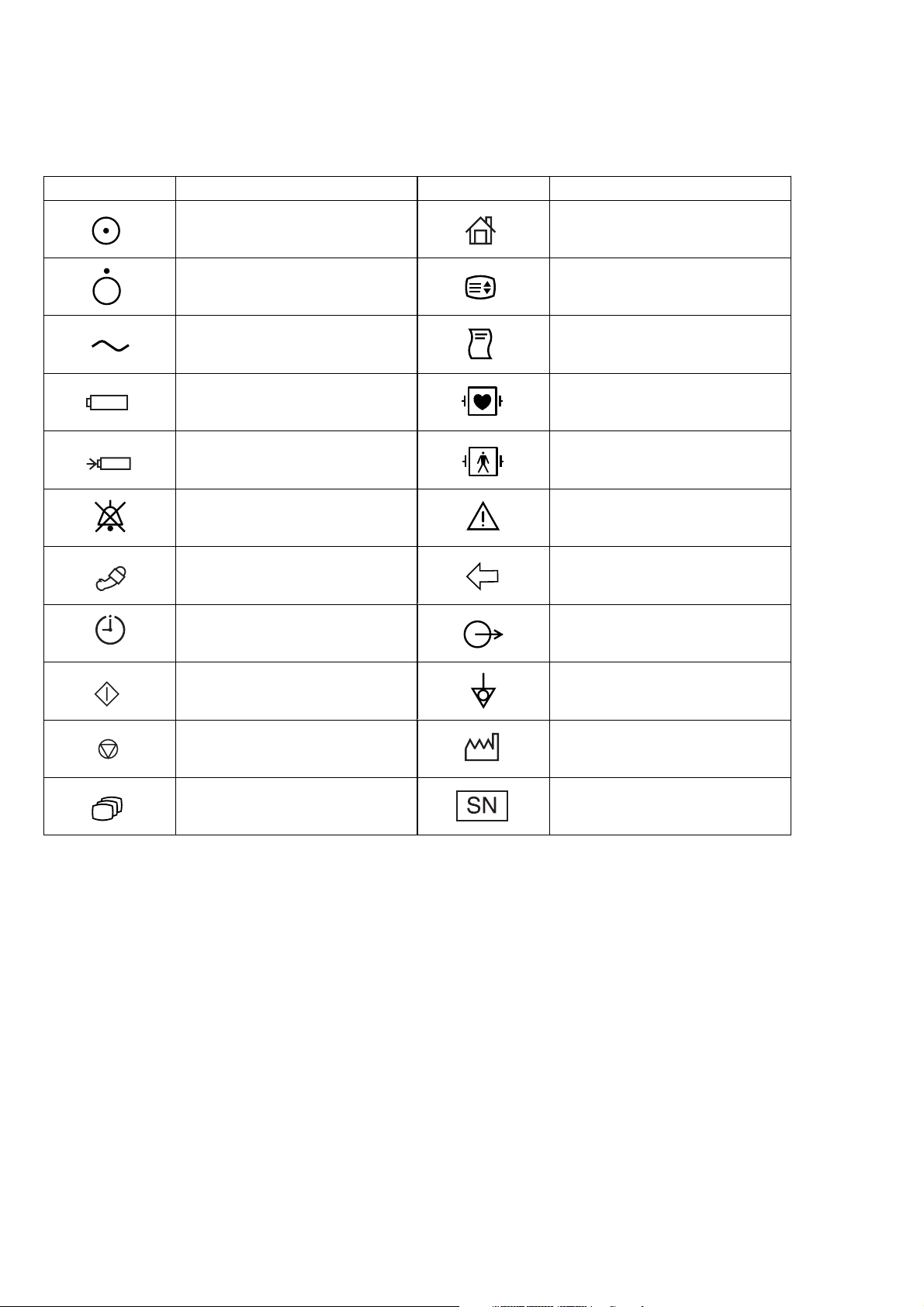
On panels
Symbol Description Symbol Description
Monitor power on Home (monitoring screen)
Monitor power off Setting screen
AC operation (front panel)
Alternating current (rear panel)
Battery operation
Battery charging
Alarm silence
NIBP ZB-900PK transmitter socket
NIBP interval Output terminal
NIBP start Equipotential terminal
NIBP stop Year of manufacture
Record start/stop (for optional
recorder unit)
Defibrillation-proof type CF applied
part
Defibrillation-proof type BF applied
part
Attention, consult operator’s
manual
Review Serial number
vi Operator's Manual OPV-1500K
Page 16
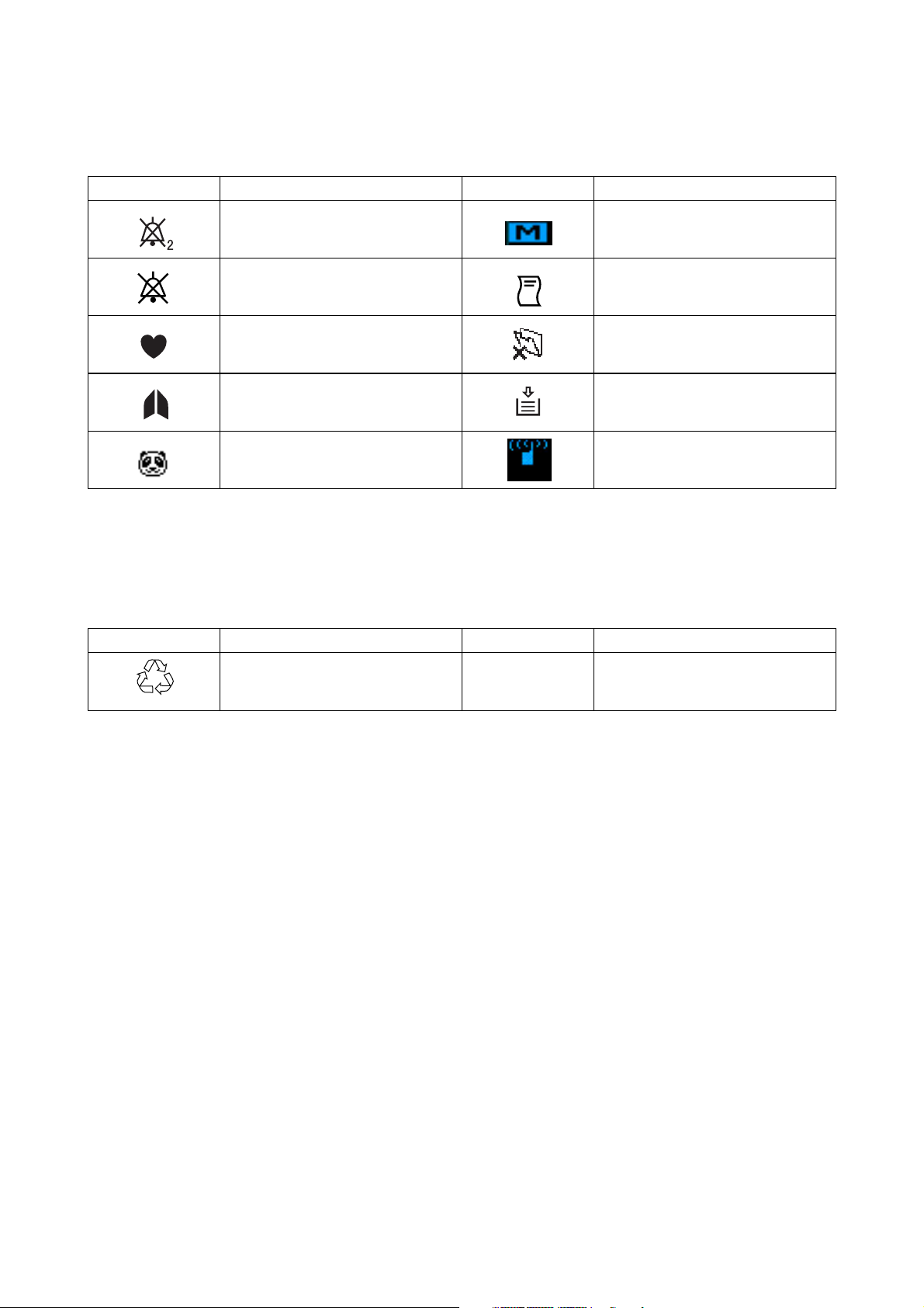
On screen
Symbol Description Symbol Description
Alarm silence with remaining
minutes
Alarm off Recording
QRS/pulse sync mark
Respiration sync mark
NIBP measurement on neonate
Others
Symbol Description Symbol Description
Body movement (SpO
Recorder door open (when using
optional recorder unit)
Out of paper (when using optional
recorder unit)
Transmitter connected to the
monitor
2)
Ni-MH
Recycle (On battery pack)
IPX4
Splash-proof equipment
(On transmitter)
Operator's Manual OPV-1500K vii
Page 17

Section 1 General
Introduction ......................................................................................................................... 1.2
Features ..............................................................................................................................1.3
Composition ........................................................................................................................ 1.4
Panel Description ................................................................................................................ 1.5
Front Panel ................................................................................................................ 1.5
Power Panel ..............................................................................................................1.5
Socket Panel ............................................................................................................. 1.6
Right Side Panel ........................................................................................................1.6
Rear Panel ................................................................................................................ 1.7
Basic Operating Concepts ................................................................................................... 1.8
Screen Displays ........................................................................................................1.8
Displaying Monitoring Screen and Review Windows ................................................1.10
Displaying Setup Windows ...................................................................................... 1.11
Changing a Setting ..................................................................................................1.12
General Safety Information ............................................................................................... 1.13
General .................................................................................................................... 1.13
Installation .............................................................................................................. 1.14
Using KC-012P Cart ................................................................................................ 1.15
Using ZB-900PK Transmitter ................................................................................... 1.15
Using YL-001P Alarm Pole ...................................................................................... 1.15
Battery .................................................................................................................... 1.16
ECG Monitoring .......................................................................................................1.17
Respiration Monitoring ............................................................................................. 1.18
SpO2 Monitoring ...................................................................................................... 1.19
NIBP Monitoring ......................................................................................................1.21
Maintenance ........................................................................................................... 1.22
Operator's Manual OPV-1500K 1C.1
Page 18

1. GENERAL
Section 1 provides a general overview of the equipment and how to operate it. If
you have not used an OPV-1500K bedside monitor before, read this section first.
• Features
• Components in the system
• Panel descriptions
• Screen displays
• Basic operation concepts
• Important safety information
Operator's Manual OPV-1500K 1.1
Page 19

1. GENERAL
Introduction
The Life Scope N OPV-1500K hardwire bedside monitor can monitor ECG,
impedance method respiration, SpO
lightweight design lets you use this bedside monitor in the general ward,
examination room, dialysis room, treatment room and for patient transport. For
portability, it can operate on battery power as well as AC power.
and NIBP. Its easy operation and compact
2
NOTE
Use only Nihon Kohden parts and accessories to assure maximum
performance from your instrument.
1.2 Operator’s Manual OPV-1500K
Page 20

Features
1. GENERAL
• Hardwire system
Monitors ECG, impedance method respiration, SpO
• AC or battery (option) operation
The monitor can operate on AC power or battery for up to 1 hour.
• Color data display
Detailed information is displayed on the wide angle, 5.6 inch color LCD.
Monitoring parameters are automatically identified.
• Easy operation by the hard keys and rotary dial
The monitor can be easily operated using the hard keys and rotary dial on the
panel.
and NIBP.
2
• Review windows for viewing saved data
Saved data can be displayed on the trendgraph window and list window.
• Thermal array recorder with 60 mm width paper (option)
Waveforms, numeric data, trendgraphs, and vital signs lists can be recorded
manually or automatically on the optional RG-101W recorder unit. Up to two
channels can be recorded.
• Telemetry system (option)
When the optional ZB-900PK transmitter is connected to the bedside monitor,
waveform(s) and parameter data from the bedside monitor can be sent to a
Cardiac Telemetry System or to a Central Monitor via a Multiple Patient
Receiver and recorded. (Available waveforms and parameter data depend on the
receiving monitor.)
Operator's Manual OPV-1500K 1.3
Page 21

1. GENERAL
Composition
SILENCE
ALARM
INTERVAL
NIBP
START
STOP
MENU/SET
SELECT
Life Scope N Bedside Monitor
OPV-1500K
Options
Accessory Kit, YZ-023H5/YZ-023H6/YZ-023H7/YZ-023H8 (option)
Cart, KC-012P (option)
Recorder Unit, RG-101W (option)
Alarm Pole, YL-001P (option)
Battery Pack, NKB-302 (option)
Transmitter, ZB-900PK (option)
1.4 Operator’s Manual OPV-1500K
Page 22
Panel Description
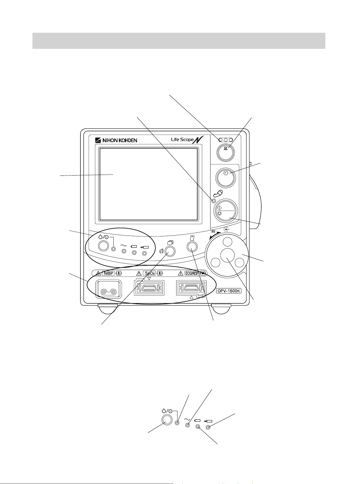
Front Panel
1. GENERAL
Alarm indicator
Red or yellow lamp blinks or lights according to the alarm settings.
NIBP lamp
Lights during NIBP measurement.
Screen
Displays
monitoring data.
Power panel
Refer to the "Power
Panel" section.
Socket panel
Refer to the "Socket
Panel" section.
SELECT
SILENCE
ALARM
INTERVAL
NIBP
START
STOP
MENU/SET
SILENCE ALARM key
Silences the alarm sound.
When the power key is pressed
while this key is pressed, the
MAINTENANCE MODE
screen is displayed for the
SYSTEM SETUP settings and
servicing.
NIBP INTERVAL key
Selects NIBP measurement
mode. Pressing this key
changes the mode.
NIBP START/STOP key
Starts NIBP measurement
in selected mode. Pressing
this key during measurement
stops measurement.
Rotary dial
Selects item on the setup
windows.
Scrolls data on the review
windows.
Center key
Displays the setup windows
and registers the setting.
Screen select key
Changes the screen in the following order:
Record key
Press to start or stop recording.
Monitoring screen, list window, trend window, sleep mode screen.
Displays monitoring screen when pressed on the setup window.
Power Panel
Power lamp
Lights when the
monitor is turned on.
AC power lamp
Lights when the power cord is connected
between the AC SOURCE socket and AC outlet.
Battery charging lamp
Indicates the battery status.
Lit: Fully charged
Power key
Press and hold for more than one
second to turn the monitor on or off.
Battery power lamp
Lights when operating on battery power.
Blinking: Being charged
Operator's Manual OPV-1500K 1.5
Page 23
1. GENERAL
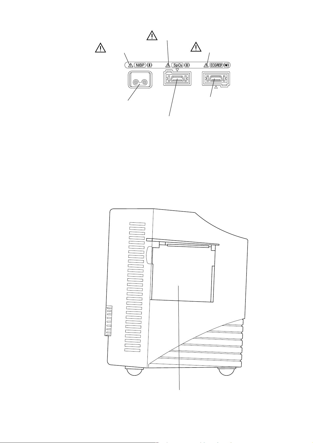
Socket Panel
Refer to Section 10.
NIBP socket
Connects to the air hose.
Refer to Section 9.
Refer to Sections 7 and 8.
ECG/RESP socket
Connects to the ECG connection cord.
SpO2 socket
Connects to the SpO2 connection cord.
Right Side Panel
RG-101W recorder unit (option)
1.6 Operator’s Manual OPV-1500K
Page 24
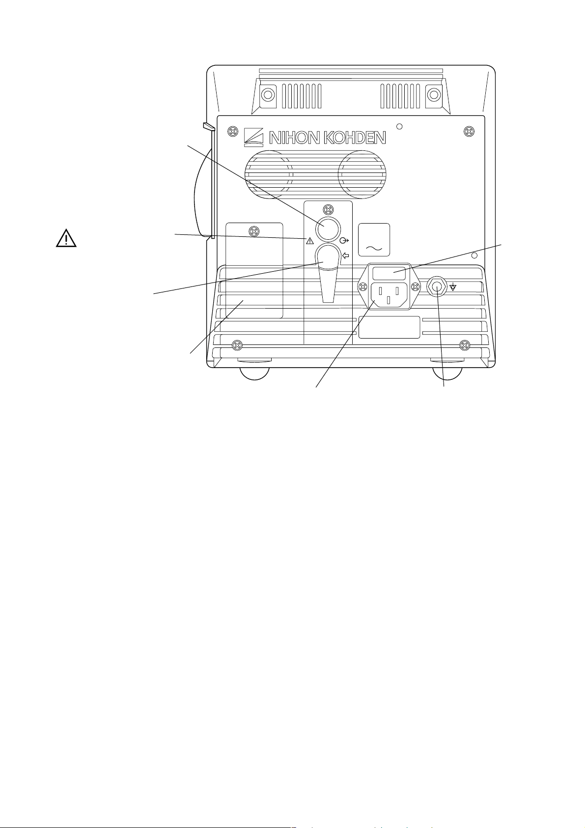
Rear Panel
Alarm pole socket
Connects the YL-001P
alarm pole (optional).
Refer to warnings and
cautions in Section 2.
ZB socket
Connects the ZB-900PK
transmitter (optional).
AUX
ZB
100 to 240V
50,60Hz
1. GENERAL
Fuse holder
Battery box
Installs the battery
pack (optional).
AC SOURCE power cord socket
Connects the AC power cord.
Equipotential grounding terminal
For an equipotential grounding lead.
Operator's Manual OPV-1500K 1.7
Page 25
1. GENERAL
Basic Operating Concepts
Screen Displays
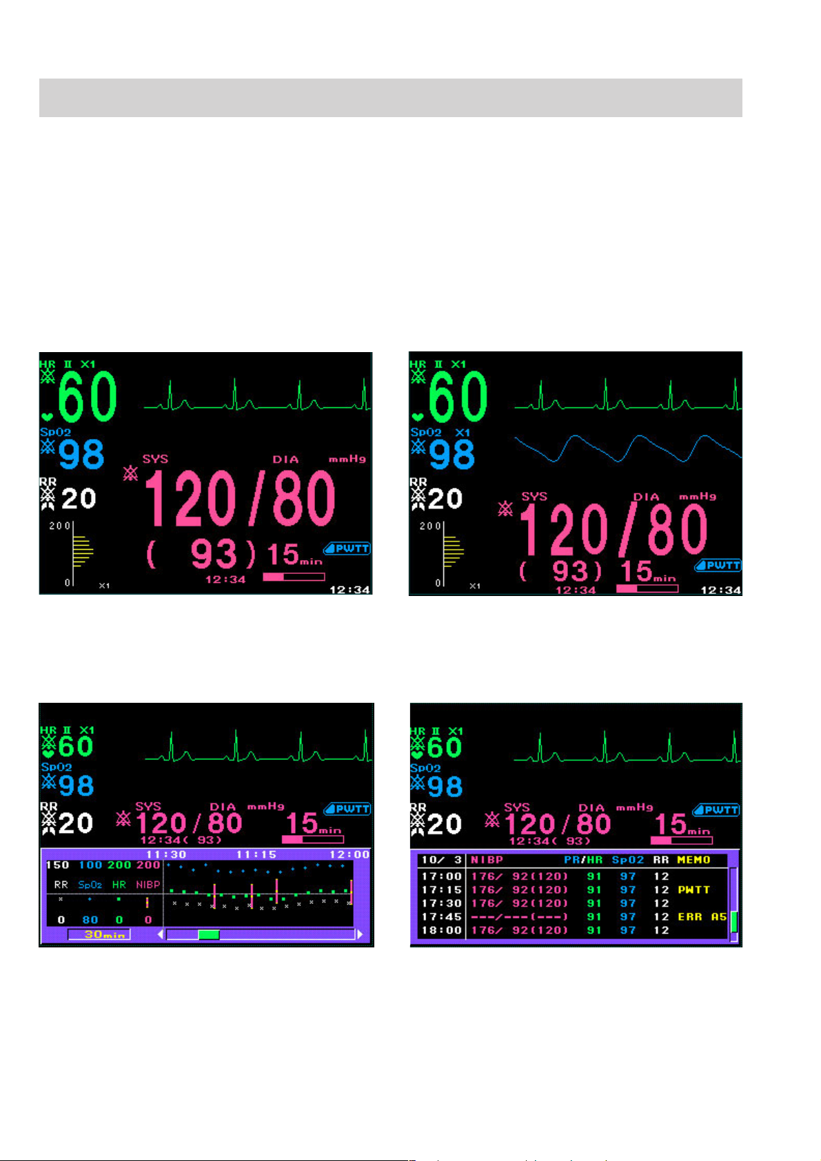
Monitoring screen
Following are the screens and windows available on the Life Scope N bedside
monitor. For details about the individual screens and windows, see the appropriate
section.
The shadow of the previous screen may remain for a few minutes after changing
the screen.
One waveform display Two waveform display
Review windows
Trendgraph window for displaying 24 hour trendgraph List window for displaying list of parameter data
1.8 Operator’s Manual OPV-1500K
Page 26
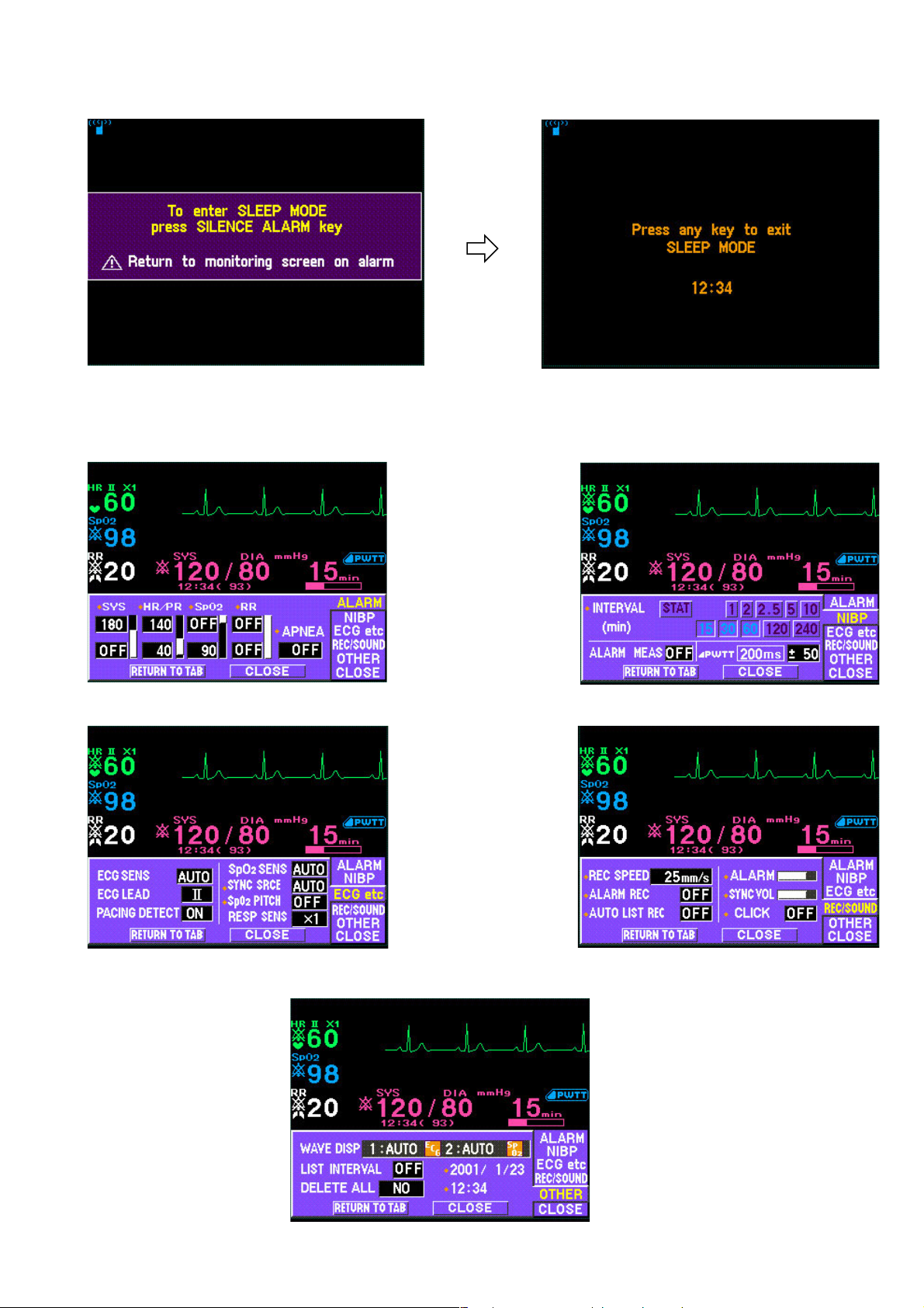
Sleep mode screen
Sleep mode confirmation screen Sleep mode screen
Setup windows
1. GENERAL
ALARM setting window
ECG etc window for changing parameter
settings other than NIBP
NIBP setting window
REC/SOUND window for setting recording
and sound settings
OTHER window for setting waveform display, list interval, date and time and deleting saved data
Operator's Manual OPV-1500K 1.9
Page 27
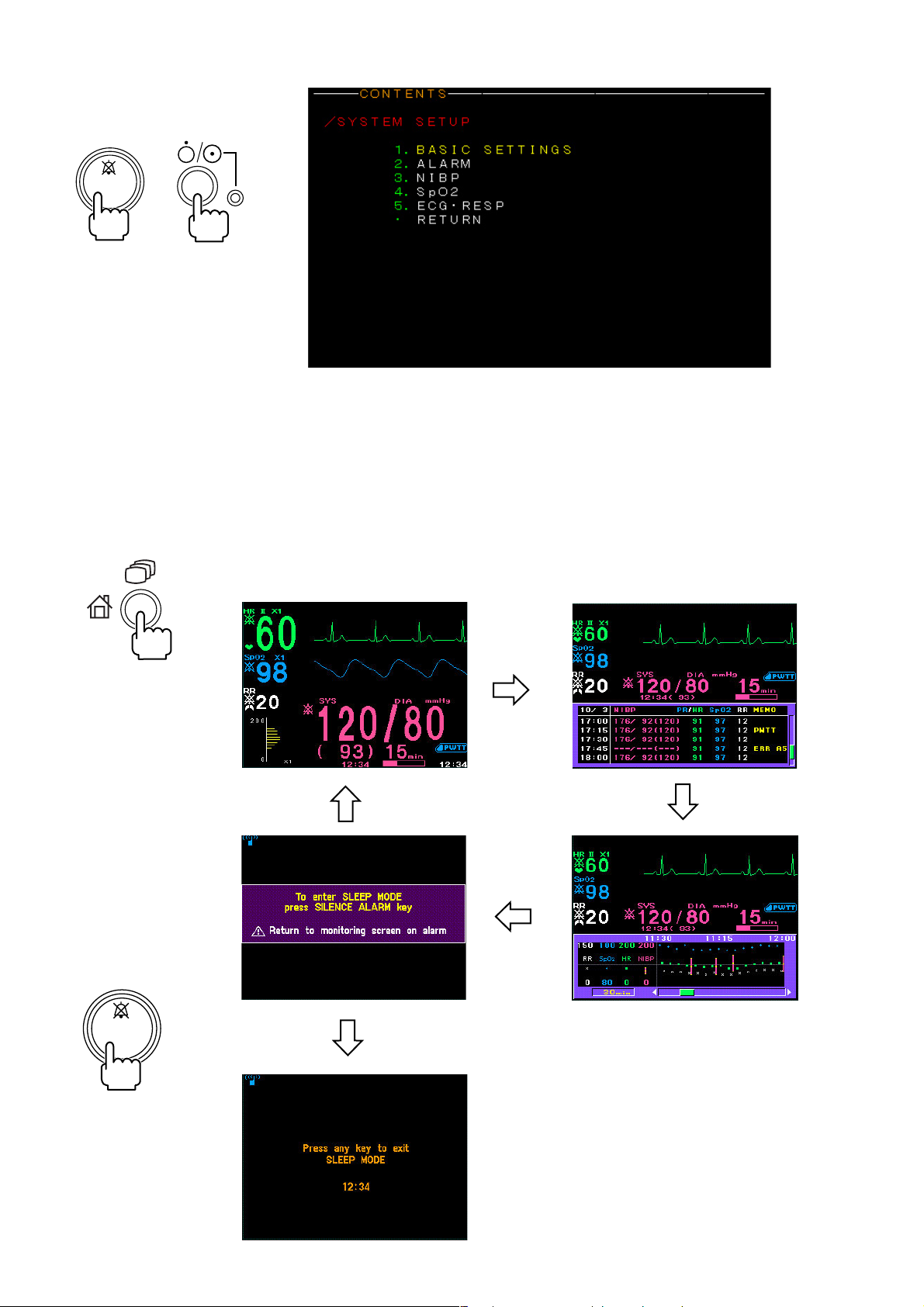
1. GENERAL
SYSTEM SETUP screen
SILENCE
ALARM
For changing system settings.
Displaying the SYSTEM SETUP
screen interrupts monitoring.
+
Displaying Monitoring
Screen and Review
Windows
Pressing the HOME/REVIEW key on the front panel changes the screen in the
following order.
Monitoring → list window → trendgraph window → sleep mode confirmation
screen→ monitoring
Pressing the SILENCE
ALARM key on the sleep
mode confirmation screen
enters sleep mode
SILENCE
ALARM
1.10 Operator’s Manual OPV-1500K
Page 28
1. GENERAL
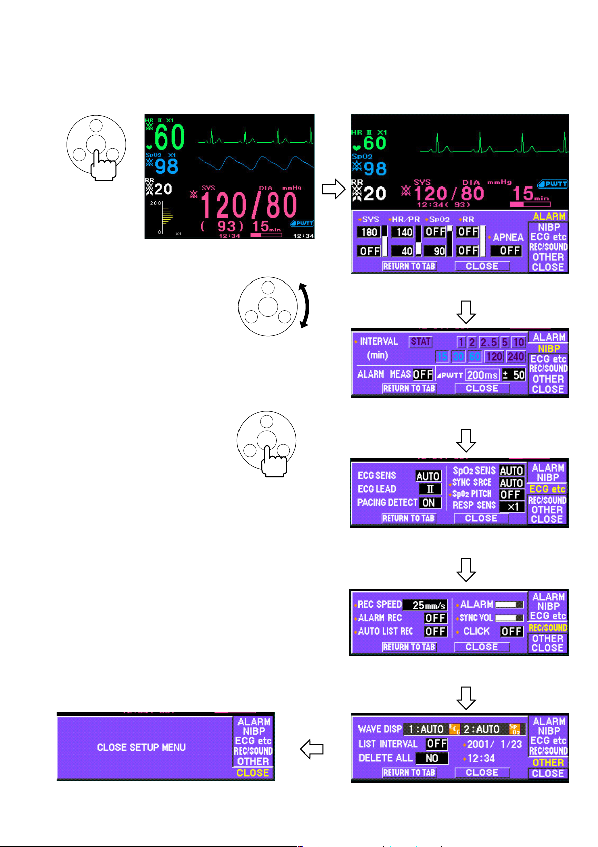
Displaying Setup Windows
Press the rotary
dial center key on
the monitoring
screen
From the monitoring screen, press the rotary dial center key on the front panel.
The ALARM window is displayed. Turning the rotary dial changes the setup
window in the following order.
ALARM window
Turn the rotary dial to
change the setup window
The red diamond mark in front of the
setting item indicates that this setting
returns to the factory default setting
30 minutes after monitor power off.
NIBP window
Press the rotary dial center
key on the setup window to
enter the window
ECG etc window
REC/SOUND window
CLOSE window for closing the setup windows
Operator's Manual OPV-1500K 1.11
OTHER window
Page 29
1. GENERAL
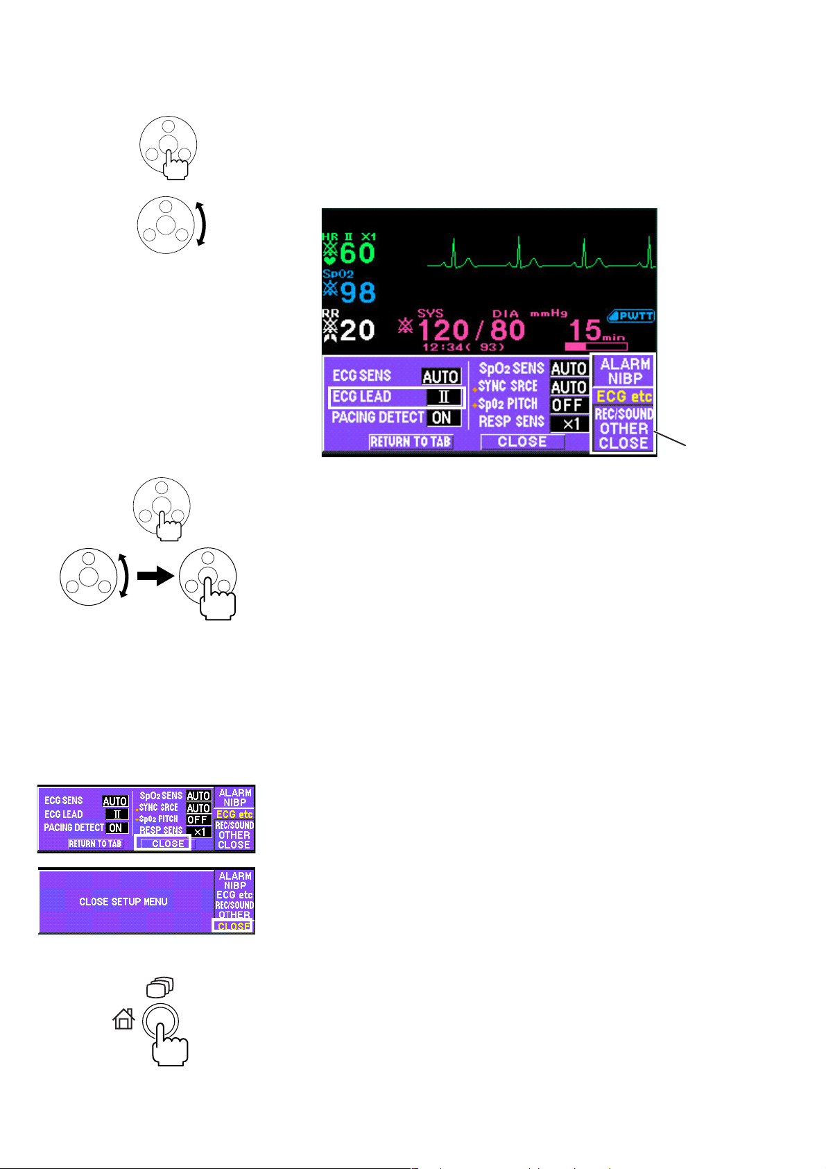
Changing a Setting For example, to change the ECG lead:
1. Display the ECG etc window.
a) From the monitoring screen, press the rotary dial center key. The ALARM
window opens.
b) Turn the rotary dial to select “ECG etc” tab.
Tabs
2. Press the rotary dial center key to enter the ECG etc window. The cursor
moves to the “ECG SENS” box.
3. Turn the rotary dial to move the cursor to “ECG LEAD” and press the rotary
dial center key to change the cursor color to blue.
4. Turn the rotary dial to select the lead and press the rotary dial center key to
register the setting.
5. To change other items on the same window, repeat steps 3 and 4.
To change settings on other windows, move the cursor to “RETURN TO TAB”
and press the rotary dial center key. The cursor moves to tab.
To close the setup window, select “CLOSE” on the setup window and press the
rotary dial center key,
or select “CLOSE” on the setup window tab and press the rotary dial center
key,
or press the HOME/REVIEW key on the front panel.
1.12 Operator’s Manual OPV-1500K
Page 30

General Safety Information
General
••
• Never use this monitor in the presence of any flammable anesthetic
••
gas, concentrated oxygen or hyperbaric oxygen. Failure to follow
this warning may result in explosion.
••
• Never use the monitor in a high-pressure oxygen medical care tank.
••
Failure to follow this warning may cause explosion or fire.
••
• When using this monitor with an electrosurgery unit, its return plate
••
and the electrodes for monitoring must be firmly attached to the
patient. If the return plate is not attached correctly, it may burn the
patient’s skin where the electrodes are attached. Refer to the
instruction manual for the ESU.
••
• When performing MRI tests, remove the electrodes and transducers
••
connected to the monitor from the patient. The heat generated from
the induced electromotive force may burn the patient’s skin. For
details, refer to the instruction manual for the MRI.
••
• When performing defibrillation, discharge as far as possible from
••
electrodes and medicine on the chest of the patient. If there is a
possibility that the defibrillator paddle could touch electrodes and
medicine, remove electrodes and medicine from the patient. If the
defibrillator directly contacts these materials, the discharged energy
may cause serious electrical burn to the patient.
••
• Before performing defibrillation, check that the cords and cables of
••
the electrodes and transducers attached to the patient are properly
connected to the monitor. Touching the metal parts of disconnected
cords and cables may cause serious electrical shock or injury by
discharged energy.
••
• To avoid the risk of serious electrical burn, shock or other injury
••
during defibrillation, all persons must keep clear of the bed and must
not touch the patient or any equipment connected to the patient.
••
• During alarm suspension, all current alarms are temporarily turned
••
off.
••
• When EXIT SLEEP MODE ON ALARM on the SYSTEM SETUP screen
••
is set to NO, the bedside monitor alarm cannot be seen or heard on
the bedside monitor during sleep mode. Attach the transmitter
(option) to the monitor and monitor the bedside monitor alarm on the
central monitor or telemetry system. Otherwise, bedside monitor
alarms may be overlooked.
1. GENERAL
WARNING
CAUTION
••
• Use only Nihon Kohden specified electrodes, probes and cuffs.
••
Otherwise, the maximum performance from the monitor cannot be
guaranteed.
••
• Do not reuse disposable parts.
••
Operator's Manual OPV-1500K 1.13
Page 31

1. GENERAL
••
• Turn off the power of cell telephones, small wireless devices and
••
other devices which produce strong electromagnetic interference.
Otherwise, the waveforms and measurements are affected by such
interference and the displayed data may be incorrect.
••
• Before monitoring a new patient, first delete all data of the previous
••
patient. Otherwise, the data of the previous patient and new patient
will be mixed together.
••
• Alarm recording is not performed when alarm is suspended or alarm
••
recording is set to off.
••
• When the alarm limit is turned off, there will be no alarm for that
••
parameter limit.
••
• When the “ECG CONNECTOR OFF”, “SpO2 CONNECTOR OFF” or
••
“AIR HOSE OFF” message appears on the screen, check that the
connection cords are connected to the sockets properly. Patient
cannot be monitored and the alarm does not function properly while
this message is displayed.
••
• If fluids are accidentally spilled on the monitor, take the bedside
••
monitor out of service and check for damage.
Installation
WARNING
••
• For patient safety, equipotential grounding of all instruments must
••
be performed. Consult with a qualified biomedical engineer.
••
• Only use the provided power cord. Using other power cords may
••
result in electrical shock or other injury to the patient and operator.
••
• When the provided power cord cannot be used or when equipotential
••
grounding is doubtful (such as in poor grounding facility), operate
the monitor on battery power.
••
• Connect only the specified instrument to the socket marked with
••
by following the specified procedure. Otherwise, electrical leakage
current may harm the patient and operator.
CAUTION
••
• When connecting the monitor to other instruments, the connection
••
must comply with IEC60601-1-1. Refer to “General Requirements for
Connecting Medical Electrical System” in Section 13.
••
• Disconnect the power cord of all instruments from the AC SOURCE
••
socket before connecting the instruments. Otherwise there may be
an electrical shock.
••
• Avoid locations where the monitor and system may be sprinkled with
••
water or chemical solutions. Otherwise the monitor and system may
be damaged.
••
• When not using the KC-012P cart, make sure that the monitor is
••
1.14 Operator’s Manual OPV-1500K
Page 32

Using KC-012P Cart
1. GENERAL
placed and fastened so that it does not tip over.
••
• Install the monitor and ESU appropriately and perform equipotential
••
grounding. Otherwise, noise from the ESU may interfere with the
ECG and ECG monitoring may not be performed properly.
••
• When the monitor power is turned on, check that one “bong” sounds
••
and the red and orange alarm indicators blink once to show that the
alarm functions properly.
Also read the warning and caution in “Selecting a Suitable Location” in Section 2.
CAUTION
••
• Use only the KC-012P cart for the OPV-1500K bedside monitor. If
••
another cart is used, it may tip over or the monitor may fall off.
••
• When the monitor is mounted on the cart, confirm that the lever on
••
the holder completely springs up. If the monitor is not locked, it may
fall off.
Using ZB-900PK
Transmitter
Using YL-001P Alarm Pole
CAUTION
Heart rate may differ between the monitor and the telemetry system or
central monitor due to the difference on the displaying ECG waveform.
CAUTION
••
• Firmly connect the alarm pole connector to the alarm pole socket on
••
the monitor. Otherwise, the lamp may not blink and an alarm may
not be indicated.
••
• Do not carry the monitor by holding the alarm pole. The alarm pole
••
may detach from the monitor and the monitor may fall off.
Operator's Manual OPV-1500K 1.15
Page 33

1. GENERAL
Battery
WARNING
••
• Keep the battery pack away from fire. Otherwise the battery pack
••
may explode.
••
• Do not heat the battery pack. The battery pack may explode.
••
••
• Never short-circuit the + and
••
wire or store the battery pack with metals such as necklace or hair
pins. The battery pack may short-circuit, causing the substance
inside the battery to leak or explode.
••
• Never disassemble or modify the battery pack. Never damage or
••
directly solder the sheath tube. The battery pack short-circuits, the
electrolyte comes out and the battery pack explodes.
••
• Do not subject the battery pack to a strong mechanical shock. The
••
battery may leak or explode.
••
• Do not use a battery which is damaged, such as from falling. There
••
is a gas discharge valve inside the battery and if this valve is
damaged, the gas cannot be discharged, causing the battery to
explode.
••
• Only use the battery pack on the specified instrument. If the battery
••
is used on an unspecified instrument, large current may flow,
causing the battery to explode.
••
• If the battery pack is damaged and the substance inside the battery
••
(alkaline liquid) contacts the eyes or skin, wash immediately and
thoroughly with water and see your physician. Never rub your eyes,
otherwise you may lose your eyesight.
••
• The battery pack has + and
••
installed with the correct polarity direction. Otherwise, the
substance inside the battery may leak and explode.
••
• Do not connect the battery pack to an AC outlet or lighter socket in a
••
car. The battery may explode.
••
• Do not immerse the battery pack in water or seawater. The battery
••
will rust and may heat up.
••
• Never use a battery pack which is damaged, discolored or has
••
leakage. A damaged battery may explode if used.
••
• Do not leave the battery for more than two years unused. The battery
••
may leak.
−−
− terminals on the battery pack with a
−−
−−
− polarity. Make sure that the battery is
−−
CAUTION
••
• Do not expose the battery pack to direct sunlight or leave in a high
••
temperature place. The lifetime of the battery pack may be shortened
or the substance inside the battery pack may leak.
••
• The battery pack must be replaced by qualified service personnel.
••
••
• Keep the battery pack away from children.
••
••
• Before disposing of the battery, check with your local solid waste
••
officials for details in your area for recycling options or proper
disposal. The battery is recyclable. At the end of its useful life,
under various state and local laws, it may be illegal to dispose of this
1.16 Operator’s Manual OPV-1500K
Page 34

ECG Monitoring
1. GENERAL
battery into the municipal waste stream.
WARNING
Interaction Between Minute Ventilation Rate-Adaptive Pacemakers and
Cardiac Monitoring and Diagnostic Equipment*
The bioelectric impedance measurement sensor of a minute ventilation
rate-adaptive implantable pacemaker may be affected by cardiac
monitoring and diagnostic equipment which is connected to the same
patient. If this occurs, the pacemaker may pace at its maximum rate
and give incorrect data to the monitor or diagnostic equipment. If this
occurs, disconnect the monitor or diagnostic equipment from the
patient or change the setting on the pacemaker by referring to the
pacemaker’s manual. For more details, contact your pacemaker
distributor or Nihon Kohden distributor.
* Minute ventilation is sensed in rate-adaptive pacemakers by a technology known
as bioelectric impedance measurement (BIM). Many medical devices in addition
to pacemakers use this technology. When one of these devices is used on a
patient with an active, minute ventilation rate-adaptive pacemaker, the
pacemaker may erroneously interpret the mixture of BIM signals created in the
patient, resulting in an elevated pacing rate.
For more information, see the FDA web site.
http://www.fda.gov/cdrh/safety.html
WARNING
••
• When using a defibrillator together with the monitor, use Ag/AgCl
••
electrodes. Other types of electrodes, stainless steel in particular,
adversely affect the ECG waveform by slowing the baseline recovery
on the monitor and result in no monitoring immediately following
defibrillation.
••
• False heart rate indicators may occur with certain pacemakers
••
because of electrical overshoots.
••
• Pacemaker patients can only be monitored when the pace program is
••
activated.
••
• Keep pacemaker patients under close observation. The pacemaker
••
rate may be counted during cardiac arrest and certain arrhythmias.
Do not rely only on the monitor.
Operator's Manual OPV-1500K 1.17
Page 35

1. GENERAL
CAUTION
••
• Use only Nihon Kohden products and specified parts and
••
accessories. When other type of electrodes are used, the “CHECK
ELECTRODE” message may be displayed and monitoring may stop.
••
• Do not reuse disposable electrodes.
••
••
• When using the electrodes with DIN type lead, use only the Vitrode V
••
or N electrodes. If other electrodes are used, the electrode lead may
not be properly connected and ECG monitoring may be unstable.
••
• If the contact is bad even before the expiration date printed on the
••
package, replace the electrode with a new one.
••
• When the “CHECK ELECTRODE” message is displayed, ECG is not
••
monitored properly. Check the electrode, electrode leads and
connection cord, and if necessary, replace it with a new one.
••
• When using the monitor with an ESU, locate the monitor and ESU
••
following the description in “Use with an Electrosurgical Unit” in
Section 7 and ground the instruments properly. Otherwise noise
from the ESU may interfere with the ECG and the heart rate and
arrhythmia analysis may be incorrect.
••
• Turn the pacing spike detection to On when monitoring a pacemaker
••
patient. Otherwise QRS and pacemaker spike may not be
distinguished and pacemaker failure may not be recognized.
Respiration Monitoring
WARNING
Interaction Between Minute Ventilation Rate-Adaptive Pacemakers and
Cardiac Monitoring and Diagnostic Equipment*
The bioelectric impedance measurement sensor of a minute ventilation
rate-adaptive implantable pacemaker may be affected by cardiac
monitoring and diagnostic equipment which is connected to the same
patient. If this occurs, the pacemaker may pace at its maximum rate
and give incorrect data to the monitor or diagnostic equipment. If this
occurs, disconnect the monitor or diagnostic equipment from the
patient or change the setting on the pacemaker by referring to the
pacemaker’s manual. For more details, contact your pacemaker
distributor or Nihon Kohden distributor.
* Minute ventilation is sensed in rate-adaptive pacemakers by a technology known
as bioelectric impedance measurement (BIM). Many medical devices in addition
to pacemakers use this technology. When one of these devices is used on a
patient with an active, minute ventilation rate-adaptive pacemaker, the
pacemaker may erroneously interpret the mixture of BIM signals created in the
patient, resulting in an elevated pacing rate.
For more information, see the FDA web site.
http://www.fda.gov/cdrh/safety.html
1.18 Operator’s Manual OPV-1500K
Page 36

SpO2 Monitoring
1. GENERAL
WARNING
When using an ESU, set RESP SENS to OFF. The noise from ESU is
superimposed on the waveform and the respiration measurement
cannot be monitored accurately.
WARNING
••
• Measurement may not be correct in the following cases.
••
· When the oxyhemoglobin or methemoglobin (HbCO, Met Hb)
increases abnormally.
· When dye is injected in the blood.
· When using an electrosurgical unit.
· During CPR.
· When there is body movement.
· When the pulse wave is small.
••
• Check the circulation condition by observing the skin color of the
••
measuring site and pulse waveform. Change the measuring site
every 8 hours for disposable probes and every 4 hours for reusable
probes. The skin temperature may increase at the attached site by 2
or 3°C (4 or 5°F) and cause a burn or pressure necrosis. When using
the probe on the following patients, take extreme care and change
the measurement site more frequently according to symptoms and
degree.
· A patient with a fever
· A patient with peripheral circulation insufficiency
· Neonate or low birth weight infant with delicate skin
••
• To avoid poor circulation, do not wrap the tape too tight. Check the
••
blood circulation condition by observing the skin color and
congestion at the skin peripheral to the probe attachment site. Even
for short-term monitoring, there may be burn or pressure necrosis
from poor blood circulation, especially on neonates or low birth
weight infants whose skin is delicate. Accurate measurement cannot
be performed on a site with poor peripheral circulation.
••
• When not monitoring SpO2, disconnect the SpO2 connection cord
••
from the bedside monitor. Otherwise, noise from the probe sensor
may interfere and incorrect data is displayed on the screen.
••
• Do not use the probe during MRI examination because it may cause
••
skinburn on the probe attachment area. For details, follow the MRI
operator’s manual.
CAUTION
••
• Turn off the power of cell telephones, small wireless devices and
••
other devices which produce strong electromagnetic interference.
Operator's Manual OPV-1500K 1.19
Page 37

1. GENERAL
Otherwise, the waveforms and measurements are affected by such
interference and the displayed data may be incorrect.
••
• Only use the specified probes. Otherwise SpO
••
cannot be monitored
2
properly.
••
• Do not use a disassembled or damaged probe because measured
••
data may be incorrect.
••
• Do not use the probe over its stated lifetime. Otherwise the SpO
••
2
measurement accuracy cannot be guaranteed.
••
• If the skin gets irritated by the tape, change the attachment site.
••
••
• Do not attach the probe to the same limb that is used for NIBP
••
measurement or an IBP catheter.
••
• Normally external light does not affect monitoring, however, strong
••
light such as an operating lamp or sunlight may affect monitoring. If
affected, cover the measuring site with a blanket.
••
• When attached, make sure that the photo emitter and the detector of
••
the probe face each other. Otherwise, SpO2 cannot be measured
properly.
••
• Do not reuse the disposable probes for another patient.
••
••
• Disposable probes are not sterilized. To sterilize the probe, refer to
••
the “Sterilizing the Disposable Probe” in Section 12.
••
• When the probe is attached on an appropriate site with sufficient
••
circulation and the error message confirming the probe attachment
repeatedly appears, the probe may be deteriorated. Replace it with a
new one.
••
• When the probe or SpO2 connection cord failure message appears on
••
the screen, replace it with a new one. Otherwise SpO2 data may not
be accurate.
••
• When the attachment site is wet with blood or when the patient has
••
nail polish on, remove dirt and nail polish before attaching the probe.
The transmitted light may decrease due to blood or nail polish and
the measurement data may be incorrect.
••
• To minimize body movement for stable SpO2 monitoring, fasten the
••
cable with the provided adhesive tape.
••
• Do not pull or bend the probe cable, and do not put caster feet on the
••
probe cable. Do not immerse the probe cable in detergents or water.
Failure to follow these cautions may cause cable discontinuity, short
circuit, skin burn on the patient and incorrect measurement data.
Replace any broken probe with a new one.
••
• When using a disposable probe, be careful when removing the foam
••
tape from neonatal skin.
••
• When removing a disposable probe that is taped to the skin, do not
••
pull the cable part of the probe because this can damage the probe’s
cable connection.
••
• Refer to the probe instruction manual for details.
••
1.20 Operator’s Manual OPV-1500K
Page 38

NIBP Monitoring
1. GENERAL
WARNING
••
• NIBP measurement on a sickle cell anemia patient may cause a
••
thrombus.
••
• When attaching the cuff to a premature infant at an early stage after
••
birth, periodically change the cuff position to avoid possible skin
erosion and fissure.
••
• While performing STAT (continuous) measurements many times
••
without a pause, periodically check the blood vessels and limb for
adequate circulation.
••
• When performing long term measurements at intervals less than 2.5
••
minutes, periodically check the state of the patient, blood vessels
and limb for adequate circulation.
CAUTION
••
• Only use the specified cuff. Otherwise NIBP monitoring cannot be
••
performed properly or the monitor may be damaged.
••
• Select the cuff which fits each patient. If the cuff size is not correct,
••
measurement may not be completed or the result may be erroneous
due to the different deflation speed of the cuff.
••
• The YP-950T/951T/952T/953T/954T/955T reusable cuffs contain
••
natural rubber latex which may cause allergic reactions.
••
• Do not reuse the disposable cuff.
••
••
• Disposable cuffs are not sterilized. If necessary, sterilize the cuff
••
using glutaraldehyde solution.
••
• The non-sterilized disposable cuffs for neonates cannot be sterilized.
••
If necessary, use the sterilized disposable cuffs for neonates.
••
• Never sterilize the disposable cuff for neonates.
••
••
• Do not wrap the cuff on an arm or thigh which is used for injection.
••
NIBP measurement on an arm or thigh which is used for injection
may cause reflux of blood and stop injection.
••
• Confirm that the air hoses are firmly connected between the sockets
••
and hoses of the cuff. If not connected properly (the air hose
connector clicks and the red color of the NIBP socket is completely
hidden behind the air hose connector when properly inserted into the
socket), the cuff cannot be correctly identified and air leakage will
cause incorrect NIBP data or no data.
••
• When too much pressure is applied to the cuff, or the hose is folded
••
or kinked, the “NIBP SAFETY VALVE OPEN” message appears on the
screen and NIBP monitoring may be stopped. Remove the cause,
wait for 40 seconds, check that the message disappears, then
measure again.
••
• If the hose is folded or squeezed, it will cause incorrect NIBP data
••
due to the air pressure noise.
••
• Do not rely only on the PWTT to monitor blood pressure changes.
••
When it is necessary to monitor critical blood pressure change, set
the appropriate interval for NIBP measurement.
Operator's Manual OPV-1500K 1.21
Page 39

1. GENERAL
••
• When the delta PWTT threshold is too short for a patient, NIBP
••
measurement may be performed too frequently. If this occurs,
change the delta PWTT threshold to a longer time.
••
• The PWTT may be incorrect when there is too much arrhythmia or
••
noise.
••
• In the following cases, PWTT may trigger too many or no NIBP
••
measurements. Check the patient condition. If necessary, change
the delta PWTT threshold or set PWTT to Off.
· Rapid blood pressure change with vasoreflex due to vasoactive
drugs, such as phenylephrine and nicardipine.
· Unstable pulse wave due to poor peripheral circulation.
· Too many arrhythmias.
· Patient movement.
· Noise on ECG due to ESU.
· SpO2 measurement on foot of a child.
••
• Do not measure NIBP with PWTT on a neonate because circulation of
••
a neonate changes rapidly.
Maintenance
CAUTION
••
• Do not disassemble the monitor. Disassembly must be performed by
••
a qualified service personnel.
••
• Fuses must be replaced by a qualified service personnel.
••
••
• Do not use volatile liquids such as thinner or benzine, because these
••
will cause the materials to melt or crack.
••
• Before cleaning the monitor, turn the monitor power off and
••
disconnect the power cord from the AC SOURCE power cord socket
on the right side panel.
••
• After cleaning, make sure that the monitor is completely dried.
••
••
• Wipe the monitor thoroughly after disinfecting it with spray.
••
••
• The bedside monitor is not waterproof. Be careful not to let any
••
water get inside the monitor.
••
• Never sterilize the monitor because the materials may deform, crack
••
or discolor.
1.22 Operator’s Manual OPV-1500K
Page 40

Section 2 Preparations
Preparation Flowchart ......................................................................................................... 2.1
Installation Conditions ......................................................................................................... 2.2
Carrying the Monitor ............................................................................................................ 2.3
Preparing the Optional Recorder Unit .................................................................................. 2.4
Installing the Recorder Unit .......................................................................................2.4
Loading the Recording Paper .....................................................................................2.4
Connecting an External Instrument to the Monitor ............................................................... 2.6
Connecting the Optional ZB-900PK Transmitter ........................................................ 2.7
Connecting the Optional YL-001P Alarm Pole ........................................................... 2.8
Power .................................................................................................................................. 2.9
AC or Battery Power Source Selection ......................................................................2.9
Connecting the Power Cord and Grounding the Monitor .............................................2.9
Connecting the Power Cord .............................................................................2.9
Grounding the Monitor ................................................................................... 2.10
Turning the Monitor On ............................................................................................2.10
Check Before Turning On the Monitor ............................................................ 2.10
Turning the Monitor On .................................................................................. 2.11
Check After Turning On the Monitor and During Monitoring ........................... 2.11
Turning the Monitor Off ............................................................................................ 2.12
Check After/Before Turning the Monitor Off ................................................... 2.12
Power and Battery Status Indications ..................................................................... 2.13
Battery Handling and Operation ............................................................................... 2.14
Safety Information......................................................................................... 2.14
Battery Lifetime............................................................................................. 2.15
Battery Handling Procedures ........................................................................ 2.15
When Using a Battery for the First Time or After Storage ............................. 2.15
When Not Using the Monitor or Battery .........................................................2.16
When the LOW BATTERY Message Appears................................................ 2.16
Installing or Replacing the Battery ................................................................ 2.16
Charging the Battery ..................................................................................... 2.16
Disposal of Battery Pack ............................................................................... 2.17
Changing Date and Time Setting .......................................................................................2.18
Turning the Click Sound for Key Operation On or Off......................................................... 2.20
Deleting All Stored Data .................................................................................................... 2.21
Operator's Manual OPV-1500K 2C.1
Page 41

Preparation Flowchart
You may not need to do all these.
1. Install the monitor and do the procedures in Section 2.
2. Delete data of the previous patient. Refer to the “Deleting Data” section.
3. Check or change any initial settings on the SYSTEM SETUP screen. These
4. Check or change all alarm items for the patient. Refer to Section 4.
5. Check or change settings for the vital signs list and trendgraphs. Refer to
2. PREPARATIONS
items usually do not need to be changed. Refer to Section 3.
Section 5.
6. Check or change recording settings. Refer to Section 6.
7. Prepare the equipment (electrodes, probes, cuffs, etc.) for monitoring
individual parameters and check or change the settings for each parameter.
Refer to Sections 7 to 10.
Operator's Manual OPV-1500K 2.1
Page 42

2. PREPARATIONS
Installation Conditions
Put the monitor on a stable and flat stand or on an optional KC-012P cart in a
suitable location where the screen is easy to see and does not reflect light. Follow
the cautions below.
For installing the monitor on the KC-012P cart, refer to the KC-012P cart
installation guide.
WARNING
••
• Never use this monitor in the presence of any flammable anesthetic
••
gas, concentrated oxygen or hyperbaric oxygen. Failure to follow this
warning may result in explosion.
••
• Connect only the specified instruments to the connector or sockets
••
marked with by following the specified procedure. Otherwise,
electrical leakage current may harm the patient and operator.
CAUTION
••
• Avoid collision when moving the monitor on a cart. Strong impact
••
may damage the monitor.
••
• The display screen is made of glass. Strong impact may damage it.
••
••
• Avoid a location where the monitor is sprinkled with liquids.
••
Avoid direct sprinkling, spray or moist air from a nebulizer or a
humidifier.
••
• If fluids are accidentally spilled on the monitor, take the monitor out of
••
service and check for damage.
••
• Avoid locations where the monitor may receive strong electromagnetic
••
interference such as radio or TV stations, cell phones or mobile two-
way radios.
••
• Do not use the monitor in an ambulance. The monitor may not
••
function properly in a moving vehicle.
••
• Avoid exposing the monitor to direct sunlight. The monitor life may
••
be shortened or the monitor may get damaged.
••
• Do not place the monitor in a dusty area.
••
••
• Do not place blankets or cloth over the monitor. It may affect
••
monitoring.
••
• Connect the power cord to an AC outlet which can supply enough AC
••
current to the monitor. The monitor cannot function properly with low
current.
••
• Do not place the monitor in an MRI examination room. The monitor
••
may not function properly, or noise from the monitor may interfere
with the MRI.
2.2 Operator's Manual OPV-1500K
Page 43
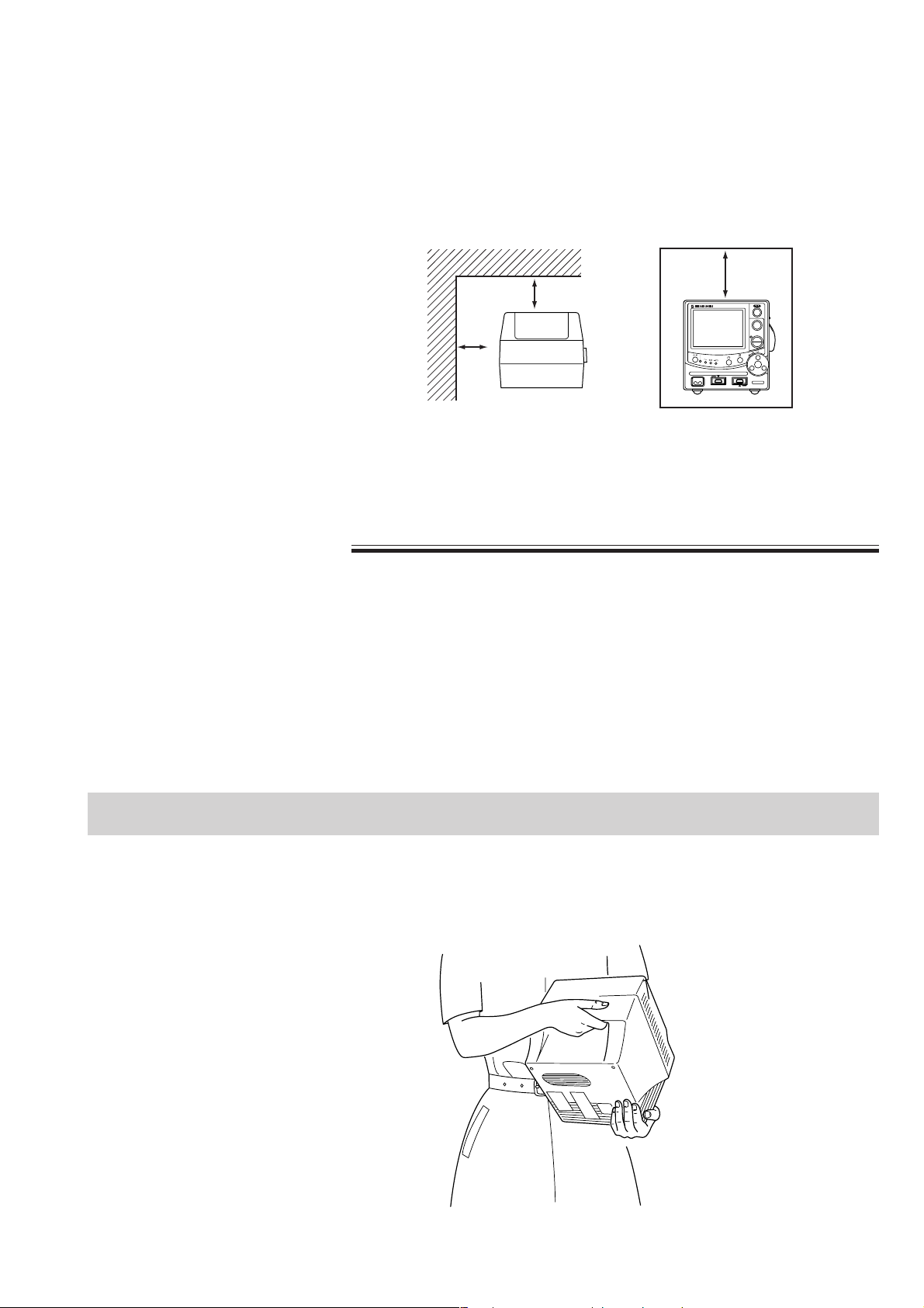
2. PREPARATIONS
••
• Do not use an electrical blanket. It may affect monitoring.
••
••
• Make sure that there is more than 5 cm of space between the monitor
••
and the wall for adequate ventilation. When the monitor is
surrounded, make sure that there is about 10 cm of space above the
monitor for ventilation so that the operating temperature does not
exceed 40°C (104°F).
10 cm
Rear
5 cm
5 cm
NIBP
Side
Avoid placing the monitor near a heater or humidifier.
••
• When there is any problem on the monitor, turn off the power
••
immediately and disconnect the power cord from the AC outlet. Take
the monitor out of service and check for damage.
Carrying the Monitor
Carry the monitor as shown below.
Operator's Manual OPV-1500K 2.3
Page 44

2. PREPARATIONS
Preparing the Optional Recorder Unit
Installing the Recorder Unit
Loading the Recording
Paper
Install the optional RG-101W recorder unit in the monitor by referring to the RG-
101W recorder unit installation guide (or OPV-1500 monitor service manual).
CAUTION for Handling the Recording Paper
••
• Do not allow paper to contact pastes, adhesive agents, oil-based felt
••
pen tips or diazo process (ditto/spirit) copying paper. These discolor
the paper surface.
••
• Do not allow paper to contact any materials made of vinyl chloride,
••
plastic eraser, adhesive tape, fluorescent felt tip pen, or cinnabar seal
ink because these discolor the recorded waveforms and data.
••
• Do not apply strong pressure to the paper. Rubbing or scratching
••
discolors the paper surface.
••
• Do not allow paper to contact saline solution. The paper discolors
••
and if the saline solution gets on the thermal head, there will be dots
missing from the recorded data.
••
• Avoid high humidity, high temperature, direct sunlight and direct
••
fluorescent light when storing recording paper. Otherwise the paper
may discolor. Store the recording paper in a dry, cool place.
••
• When using glue on the recording paper, use glue which consists of
••
starch, polyvinyl alcohol, gum arabic, or carboxymethyl.
CAUTION for Loading the Recording Paper
••
• Correctly load the recording paper as specified. Otherwise, recording
••
may not be performed properly.
••
• Do not touch the recording head with any hard material. When the
••
head is tapped with hard material, the head may crack and the heater
element wire may short-circuit.
••
• Clean the head surface with the provided head cleaner pen before
••
loading new paper. After a period of usage, paper dust may
accumulate between the paper and the head surface, and good
printing cannot be obtained.
NOTE
Only use the specified recording paper, QW60-2.
2.4 Operator's Manual OPV-1500K
Page 45
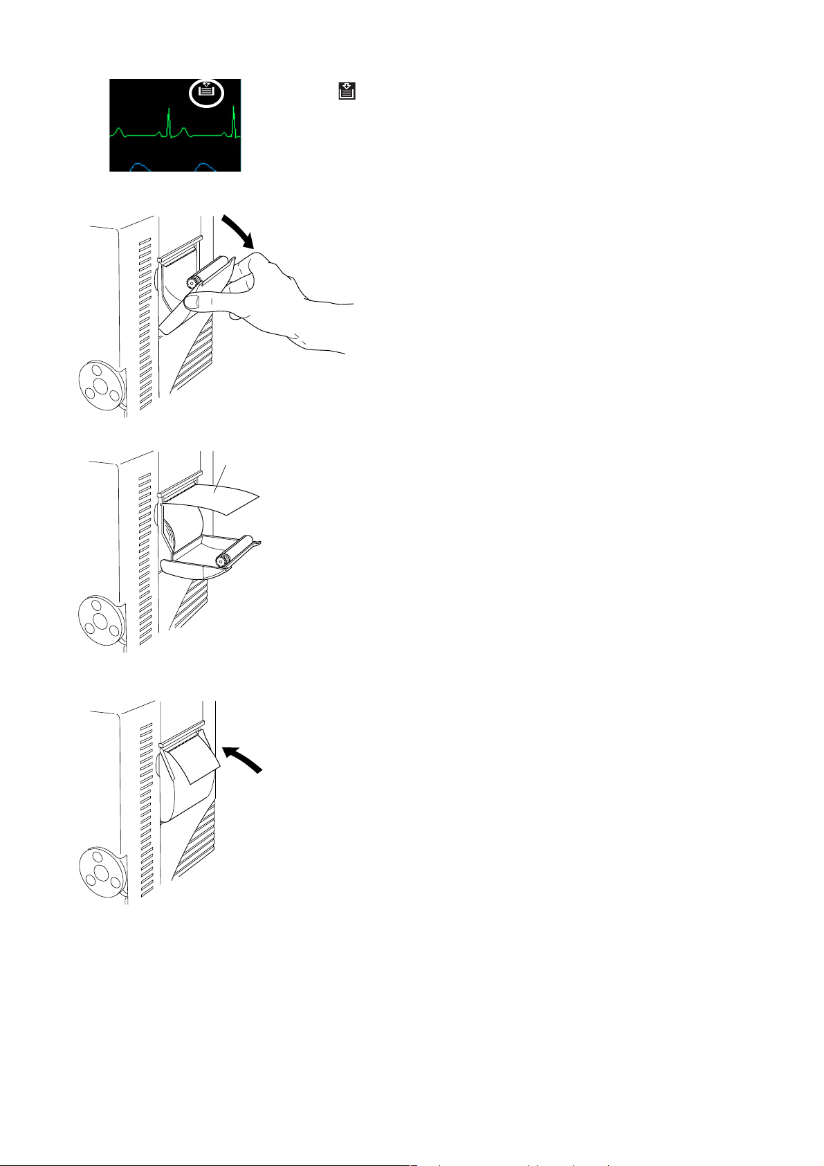
2. PREPARATIONS
The out of paper mark appears on the screen when there is no paper.
1. Open the recorder door.
Recording paper
2. Set the recording paper (QW60-2) inside the recorder as shown left.
3. Draw out some paper toward you and close the recorder door.
If the out of paper mark is still displayed on the screen, the recorder door is not
closed properly.
Operator's Manual OPV-1500K 2.5
Page 46

2. PREPARATIONS
Connecting an External Instrument to the Monitor
The optional ZB-900PK transmitter and YL-001P alarm pole can be connected to
the monitor.
WARNING
For patient safety, equipotential grounding of all instruments must be
performed. Consult with a qualified biomedical engineer.
When more than one electrical instrument is used, there may be electrical potential
difference between the instruments. Potential difference between instruments may
cause current to flow to the patient connected to the instruments, resulting in
electrical shock (micro shock). Never use any medical equipment in patient
treatment without proper grounding.
Always perform equipotential grounding as specified in IEC60601-1-1 when
required. It is often required in the operating room, ICU room, CCU room, cardiac
catheterization room and X-ray room. Consult with a biomedical engineer to
determine if it is required.
Refer to the reference “General Requirements for Connecting Medical Electrical
System” in Section 13.
WARNING
Connect only the specified instruments to the connector or sockets
marked with by following the specified procedure. Otherwise,
electrical leakage current may harm the patient and operator.
CAUTION
Disconnect the power cord of all instruments from the AC SOURCE
socket before connecting the instruments. Otherwise there may be an
electrical shock.
2.6 Operator's Manual OPV-1500K
Page 47
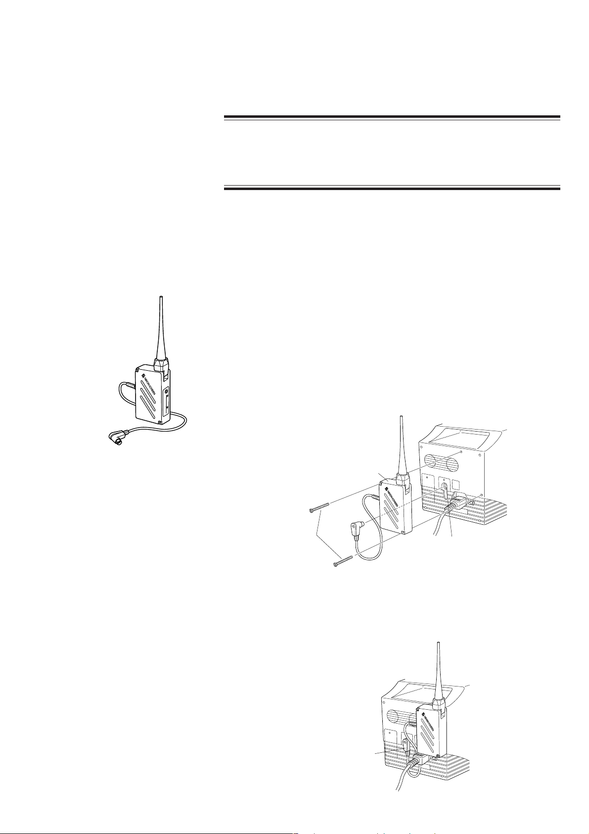
2. PREPARATIONS
Connecting the Optional
ZB-900PK Transmitter
The ZB-900PK transmitter transmits data from the monitor to a cardiac telemetry
system or central monitor. A multiple patient receiver is necessary with the central
monitors.
CAUTION
Heart rate may differ between the monitor and the telemetry system or
central monitor due to the difference on the displaying ECG waveform.
NOTE
••
• Before connecting the transmitter, turn off the monitor power.
••
••
• The ZB-900PK transmitter frequency band is 400 MHz.
••
••
• The ZB-900PK transmitter is not applicable to the CE mark.
••
••
• A ZB-800PK transmitter cannot be used on this monitor.
••
1. Check that the antenna direction of the transmitter is appropriate and that the
transmitter cable is connected to the appropriate socket as shown to the left.
Refer to the transmitter manual to change the cable connection.
2. Attach the transmitter to the rear panel of the monitor with the two screws
provided with the transmitter as shown below. (The spacers provided with the
transmitter are not required.)
ZB-900P transmitter
Screws provided
with the transmitter
ZB socket
3. Connect the transmitter cable connector to the ZB socket on the monitor.
Make sure that the transmitter cable is not in the way.
Transmitter cable connector
Operator's Manual OPV-1500K 2.7
Page 48

2. PREPARATIONS
Connecting the Optional
YL-001P Alarm Pole
Alarm pole
CAUTION
••
• Firmly connect the alarm pole connector to the alarm pole socket on
••
the monitor. Otherwise, the lamp may not blink and an alarm may not
be indicated.
••
• Do not carry the monitor by holding the alarm pole. The alarm pole
••
may detach from the monitor and the monitor may fall off.
1. Clean the area on the monitor where the alarm pole base is to be attached with
alcohol.
2. Remove the backing paper from the bottom of the alarm pole base. Firmly
press the alarm pole base to the cleaned area.
3. Insert the alarm pole into the alarm pole base.
Alarm pole base
To remove the alarm pole from the alarm pole base, pull the alarm pole upward
while holding the alarm pole base in place.
4. Connect the alarm pole cable connector to the alarm pole socket on the rear
panel of the monitor.
Lamp indication
Red: crisis, yellow: warning, green: not used
AUX
100V
50,60Hz
ZB
Alarm pole socket
2.8 Operator's Manual OPV-1500K
Page 49

Power
2. PREPARATIONS
AC or Battery Power
Source Selection
The monitor can operate on either battery or AC power.
When the power cord is plugged into an AC outlet and the power key on the front
panel is turned on, the monitor operates on AC power.
When a battery is installed and the power cord is disconnected, such as when
transferring a patient, the monitor automatically switches to battery power.
The battery is charged when the power cord is plugged into an AC outlet and the
AC current is supplied to the monitor. The battery is also charged during
monitoring.
The monitor can operate for about 1 hour with a fully charged battery pack when:
• Charged and used in normal temperature (about 25°C)
• Recorder is not used
• No alarm occurs
• Monitoring ECG, respiration and SpO
• NIBP measurement at 5 minute interval.
2
NOTE
When the monitor switches from AC to battery power or UPS, or vice
versa, some noise may interfere on the waveform and the numeric data
may not be stable. In such a case, wait for the monitor to become
stable before resuming monitoring.
Connecting the Power
Connecting the Power Cord
Cord and Grounding the
Monitor
WARNING
••
• Only use the provided power cord. Using other power cords may
••
result in electrical shock or other injury to the patient and operator.
••
• When the provided power cord cannot be used, operate the monitor
••
on battery power.
Connect the provided power cord to the AC SOURCE socket on the rear panel of
the monitor and plug the cord into a 3-prong AC outlet.
When the AC power is supplied to the monitor, the AC power lamp on the front
panel lights and a buzzer sounds.
Lit
Operator's Manual OPV-1500K 2.9
Page 50

2. PREPARATIONS
NOTE
If the AC power lamp does not light and there is no “bong” sound,
check the power cord connection.
Grounding the Monitor
WARNING
••
• For patient safety, equipotential grounding of all instruments must be
••
performed. Consult with a qualified biomedical engineer.
••
• When equipotential grounding is doubtful (such as in poor grounding
••
facility), operate the monitor on battery power.
When more than one electrical instrument is used, there may be electrical potential
difference between the instruments. The potential difference between the
instruments may cause current to flow to the patient connected to the instruments,
resulting in electrical shock (micro shock).
Turning the Monitor On
Always perform equipotential grounding when required. It is often required in the
operating room, ICU room, CCU room, cardiac catheterization room and X-ray
room. Consult with a biomedical engineer to determine if it is required.
When equipotential grounding is required, connect the equipotential ground
terminal on the instrument to the equipotential ground terminal on the wall
(equipotential grounding system) with the equipotential grounding lead (potential
equalization conductor).
Check Before Turning On the Monitor
Check the following items before turning on the monitor.
• Enough electrodes and electrode leads are ready.
• Cleaned and sterilized probes and cuffs are ready.
• Power cord is connected properly.
• Equipotential grounding lead is connected properly when equipotential
grounding is required.
• All cables are connected properly.
• Batteries are fully charged when operating on battery power.
• No scratches, damage or dirt on the monitor.
• No damage to the keys, rotary dial and panels.
• No damage to the power cord.
• No damage to the electrode leads, probes and cuffs.
• The monitor is not in a wet place.
• Enough recording paper in the recorder (when using an optional recorder unit).
2.10 Operator's Manual OPV-1500K
Page 51

2. PREPARATIONS
Turning the Monitor On
CAUTION
When the monitor power is turned on, check that one “bong” sounds
and the red and yellow alarm indicators blink once to show that the
alarm functions properly.
NOTE
••
• It takes a few minutes for the LCD screen to reach full brightness.
••
••
• The shadow of the previous screen may remain for a few minutes after
••
changing screens.
••
• There may be some dots on the LCD screen which are always on or
••
always off, but it does not affect monitoring. This is normal for all
LCD screens.
Lit
Lit Lit
Lit
When the monitor is turned on, check that one “bong” sounds and the red and
yellow alarm lamps blink once to show that the alarm functions properly.
••
• When operating on battery power
••
After installing a fully charged battery pack, press the power key on the front
panel to ON. The power and battery power lamps light, a buzzer sounds and the
monitoring screen appears.
If the power and battery power lamps do not light and there is no buzzer sound,
check the battery condition.
When operating on battery power, the screen brightness may be darker compared
to operating on AC power.
••
• When operating on AC power
••
After grounding and connecting the power cord, press the power key on the front
panel to ON. The power lamp and the AC power lamp light and the monitoring
screen appears.
If the power lamp does not light, check the power cord connection.
Check After Turning On the Monitor and During Monitoring
To start monitoring safely and properly, check the following items after turning on
the monitor. If any problem is detected, take the proper countermeasure according
to the troubleshooting and maintenance sections.
• There is no fire, smoke or smell.
• The monitor is not too hot.
• The power lamp lights.
• Alarm indicators blink once and a bong sounds.
Operator's Manual OPV-1500K 2.11
Page 52

2. PREPARATIONS
• The monitoring screen appears.
• No error message is displayed on the screen.
• The time on the screen is correct.
• The low battery mark does not appear on the screen when operating on battery.
• The monitor does not affect surrounding equipment.
• The data and waveforms are displayed properly.
• Keys and rotary dial operate properly.
• Alarm functions properly.
• There is no trouble in recording (when using an optional recorder unit).
NOTE
After turning the monitor on and before monitoring a patient, make sure
that the time displayed at the lower right of the screen is correct. The
date and time of all stored data is not changed when the current date or
time is changed during monitoring.
Turning the Monitor Off
1. Press the power key on the front panel for more than one second to turn the
monitor off. The screen becomes dark and the power lamp on the front panel
turns off.
Check After/Before Turning the Monitor Off
Check the following items for the next use.
• Previous patient data is deleted.
• Temporarily changed settings are changed back to the previous settings.
• There is no dirt, damage or scratches on the monitor.
• The cuffs, probes and cables are cleaned and sterilized.
• Accessories are cleaned and stored properly.
• There are enough consumables, such as recording paper, and disposable
electrodes for the next use.
• Battery pack is fully charged.
• Battery pack is removed from the monitor when not operating for a long period
of time.
• The power key on the monitor is turned off and the power cord is disconnected
from the monitor.
• The monitor is not in a wet place.
• Dead batteries are disposed of properly.
• The medical waste is disposed of properly.
• The monitor is stored properly.
2.12 Operator's Manual OPV-1500K
Page 53

2. PREPARATIONS
Power and Battery Status
Indications
Lit Lit
Lit Lit Lit or slow blinking
Lit
Power and battery status are indicated by four lamps on the front panel. A
discharged battery is also indicated by a screen message and alarm.
NOTE
When charging the battery with the monitor power key turned off, check
that the AC power lamp and battery charging lamp light. If the lamps do
not light even when the power cord is connected and the battery is
inserted, turn the power key on, check that the battery charging lamp is
blinking or lit, then turn the power key off.
• Operating on AC power and battery is fully charged
Power lamp: Lit
AC power lamp: Lit
Battery power lamp: Off
Battery charging lamp: Lit
• Operating on AC power and battery is being charged
Power lamp: Lit
AC power lamp: Lit
Battery power lamp: Off
Battery charging lamp: Slow blinking (once every 2 seconds) or lit
Lit Lit
Lit Rapid blinking or off
Lit
Lit
Lit
Lit
Rapid blinking
• Operating on AC power with no battery
Power lamp: Lit
AC power lamp: Lit
Battery power lamp: Off
Battery charging lamp: Off
• Operating on AC power and battery is damaged
Power lamp: Lit
AC power lamp: Lit
Battery power lamp: Rapid blinking (4 times per second) or off
Battery charging lamp: Rapid blinking (4 times per second) or off
• Operating on battery power
Power lamp: Lit
AC power lamp: Off
Battery power lamp: Lit
Battery charging lamp: Off
• Operating on battery power and battery needs recharging
Power lamp: Lit
AC power lamp: Off
Battery power lamp: Rapid blinking (4 times per second)
Battery charging lamp: Off
Screen indication: “LOW BATTERY” message
Alarm indication: Continuous “bing bong” sound and blinking
yellow alarm lamp
Operator's Manual OPV-1500K 2.13
Page 54

2. PREPARATIONS
Lit
Lit or slow blinking
• No monitoring and charging battery
Power lamp: Off
AC power lamp: Lit
Battery power lamp: Off
Battery charging lamp: Slow blinking (once every 2 seconds) or lit
Battery Handling and
Operation
Safety Information
WARNING
••
• Keep the battery pack away from fire. Otherwise the battery pack may
••
explode.
••
• Do not heat the battery pack. The battery pack may explode.
••
••
• Never short-circuit the + and
••
wire or store the battery pack with metals such as necklace or hair
pins. The battery pack may short-circuit, causing the substance inside
the battery to leak or explode.
••
• Never disassemble or modify the battery pack. Never damage or
••
directly solder the sheath tube. The battery pack short-circuits, the
electrolyte comes out and the battery pack explodes.
••
• Do not subject the battery pack to a strong mechanical shock. The
••
battery may leak or explode.
••
• Do not use a battery which is damaged, such as from falling. There is
••
a gas discharge valve inside the battery and if this valve is damaged,
the gas cannot be discharged, causing the battery to explode.
••
• Only use the battery pack on the specified instrument. If the battery is
••
used on an unspecified instrument, large current may flow, causing
the battery to explode.
••
• If the battery pack is damaged and the substance inside the battery
••
(alkaline liquid) contacts the eyes or skin, wash immediately and
thoroughly with water and see your physician. Never rub your eyes,
otherwise you may lose your eyesight.
••
• The battery pack has + and
••
installed with the correct polarity direction. Otherwise, the substance
inside the battery may leak and explode.
••
• Do not connect the battery pack to an AC outlet or lighter socket in a
••
car. The battery may explode.
••
• Do not immerse the battery pack in water or seawater. The battery will
••
rust and may heat up.
••
• Never use a battery pack which is damaged, discolored or has leakage.
••
A damaged battery may explode if used.
−−
− terminals on the battery pack with a
−−
−−
− polarity. Make sure that the battery is
−−
CAUTION
••
• Do not expose the battery pack to direct sunlight or leave in a high
••
temperature place. The lifetime of the battery pack may be shortened
2.14 Operator's Manual OPV-1500K
Page 55

2. PREPARATIONS
or the substance inside the battery pack may leak.
••
• The battery pack must be replaced by qualified service personnel.
••
••
• Keep the battery pack away from children.
••
••
• Before disposing of the battery, check with your local solid waste
••
officials for details in your area for recycling options or proper
disposal. The battery is recyclable. At the end of its useful life, under
various state and local laws, it may be illegal to dispose of this battery
into the municipal waste stream.
NOTE
••
• Fully charge the new battery pack before using on the monitor.
••
••
• Do not use a battery pack which is past the expiration date written on
••
the label.
••
• Always charge the battery between 10°C (50°F) and 30°C (86°F).
••
Temperatures out of this range affect the working of the battery and
may cause it to leak or explode.
••
• Do not leave a battery pack inside the monitor without the power cord
••
connected between the monitor and AC outlet. The battery pack may
be over-discharged and can no longer be used.
••
• When not using the monitor for a long period of time (more than six
••
months), remove the battery pack from the monitor and store the
battery at temperatures between
humidity.
••
• Before disposing of the monitor, make sure that the battery pack is
••
removed from the monitor.
−−
−20°C (
−−
−−
−4°F) and +30°C (86°F) and low
−−
Battery Lifetime
The battery pack lifetime is one year or 300 cycles of discharging/charging. Write
the date of first use of the battery on the start date label provided with the battery
pack and attach it to the bedside monitor where it is easy to see (upper part of the
right side panel recommended). Write the same date on the label of the battery
pack.
Battery Handling Procedures
• Use a battery until it is fully discharged (LOW BATTERY message appears), then
fully charge the battery. The battery life will be longer if it is fully discharged
before charging it again.
• Replace the battery with a new one after 300 cycles of discharging/charging or
after one year, whichever comes first. This is because the battery is a chemical
product which gradually deteriorates whether or not it is used.
When Using a Battery for the First Time or After Storage
• Fully recharge the battery before using it for the first time or after storing it for
over a month. When the battery is not used, it self-discharges.
Operator's Manual OPV-1500K 2.15
Page 56

2. PREPARATIONS
When Not Using the Monitor or Battery
WARNING
Do not leave the battery for more than two years unused. The battery
may leak.
• When the monitor is not used (about 6 months), remove the battery. When a
charged or discharged battery is left inside the monitor with the power cord
unplugged, the battery self-discharges and deteriorates.
• When a battery is not used, fully charge it before storage. When a battery is not
used for over one month, fully charge it before use.
• Store the battery packs under the following conditions.
Temperature: −20 to 30°C (−4 to 86°F)
Humidity: 65% ±20% relative humidity
When the LOW BATTERY Message Appears
When the “LOW BATTERY” message highlighted in yellow appears, continuous
“bing bongs” sound and the yellow alarm indicator blinks, the battery power is
weak. Connect the power cord to the monitor, operate the monitor on AC power
and charge the battery.
If no AC or battery power is supplied to the monitor, there is no measurement or
display but no data is lost.
Installing or Replacing the Battery
The battery pack must be installed or replaced by qualified service personnel.
Refer to the bedside monitor service manual.
Charging the Battery
The battery pack can only be charged by the monitor. It takes about 2 hours and
40 minutes to charge a battery pack on the monitor.
The monitor can operate for about 1 hour with a fully charged battery pack when:
• Charged and used in normal temperature (about 25°C)
• Recorder is not used
• No alarm occurs
• Monitoring ECG, respiration and SpO
2
• NIBP measurement at 5 minute intervals.
CAUTION
When charging the battery pack, keep the ambient temperature at
approximately 20°C to maintain the optimal battery operation time. If
the battery pack is charged at less than 10°C (50°F) or more than 40°C
2.16 Operator's Manual OPV-1500K
Page 57

2. PREPARATIONS
(72°F), the maximum battery operation time will be 20% to 30% less than
the optimal operation time.
During AC operation, the battery is automatically charged without interrupting
monitoring. It takes approximately 2 hours and 40 minutes of continuous
charging to fully charge the battery pack. After 2 hours and 40 minutes of
continuous charging, the monitor automatically switches to trickle charging mode
to maintain the battery pack fully charged. Trickle charging is necessary because
the battery pack can self-discharge even when it is not in use.
NOTE
••
• Do not disconnect the power cord from the monitor during battery
••
charging.
••
• If the 2 hours and 40 minutes of continuous normal charging is
••
disrupted for more than one hour by power failure in the main power
supply or by temporary removal of the battery pack from the monitor,
the monitor’s normal charging circuit is reset, and the battery pack is
charged for another 2 hours and 40 minutes regardless of how many
hours it was charged before the disruption. This deteriorates the
battery.
Lit
Lit or slow blinking
1. Install the battery pack into the monitor.
2. Connect the power cord to the monitor and the AC outlet. The monitor
charges the battery pack regardless of whether the monitor power key is on or
off.
During charging, the battery charging lamp on the front panel blinks.
After 2 hours and 40 minutes, the battery charging lamp is continuously lit
and the battery charging is completed.
Disposal of Battery Pack
Before disposing of the battery, check with your local solid waste officials for
details in your area for recycling options or proper disposal. The battery is
recyclable. At the end of its useful life, under various state and local laws, it may
be illegal to dispose of this battery into the municipal waste stream.
Operator's Manual OPV-1500K 2.17
Page 58
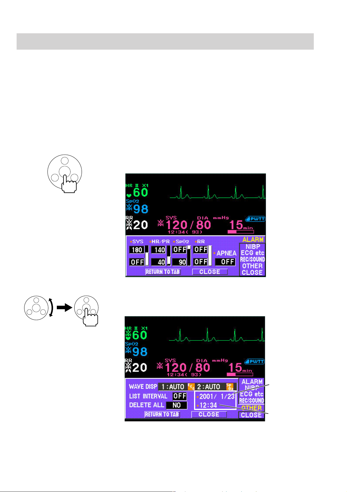
2. PREPARATIONS
Changing Date and Time Setting
When the monitor power is on, the current time is displayed in the lower right
corner of the monitoring screen.
The date and time of all stored data is not changed when the current
date or time is changed during monitoring.
The date format can be changed at DATE FORMAT on the SYSTEM SETUP
screen. Refer to Section 3.
1. From the monitoring screen, press the rotary dial center key on the front panel.
The ALARM window opens.
NOTE
2. Turn the rotary dial to select “OTHER” and press the rotary dial center key to
enter the OTHER window. The cursor moves to the “WAVE DISP” box.
Date
Time
3. Turn the rotary dial to move the cursor to date, press the rotary dial center key
to change the cursor color to blue, turn the rotary dial to select setting and
press the rotary dial center key to register the setting.
2.18 Operator's Manual OPV-1500K
Page 59

2. PREPARATIONS
To change the time, turn the rotary dial to move the cursor to time, press the
rotary dial center key to change the cursor color to blue, turn the rotary dial to
select setting and press the rotary dial center key to register the setting.
4. To return to the monitoring screen, select “CLOSE” on the OTHER window or
press the HOME/REVIEW key on the front panel.
Operator's Manual OPV-1500K 2.19
Page 60

2. PREPARATIONS
Turning the Click Sound for Key Operation On or Off
The click sound for the key and rotary dial operation can be turned on or off.
1. From the monitoring screen, press the rotary dial center key on the front panel.
The ALARM window opens.
2. Turn the rotary dial to select “REC/SOUND” and press the rotary dial center
key to enter the REC/SOUND window. The cursor moves to the “REC
SPEED” box.
3. Turn the rotary dial to move the cursor to “CLICK” and press the rotary dial
center key to select ON or OFF.
4. To return to the monitoring screen, select “CLOSE” on the REC/SOUND
window or press the HOME/REVIEW key on the front panel.
2.20 Operator's Manual OPV-1500K
Page 61
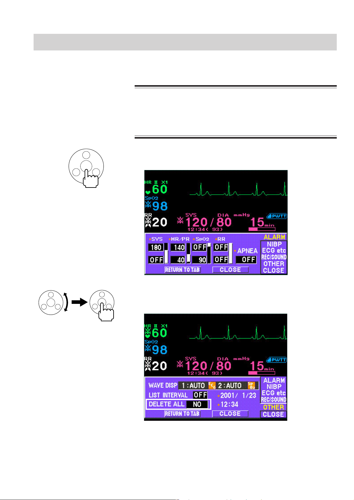
Deleting All Stored Data
When monitoring the patient is no longer required, delete the stored data.
Before monitoring a new patient, first delete all data of the previous
patient. Otherwise, the data of the previous patient and new patient will
be mixed together.
1. From the monitoring screen, press the rotary dial center key on the front panel.
2. PREPARATIONS
CAUTION
The ALARM window opens.
2. Turn the rotary dial to select “OTHER” and press the rotary dial center key to
enter the OTHER window. The cursor moves to the “WAVE DISP” box.
3. Turn the rotary dial to move the cursor to “DELETE ALL”, press the rotary dial
center key to change the cursor color to blue, turn the rotary dial to select
“YES” and press the rotary dial center key to delete data.
To not delete data, select “NO” and press the rotary dial center key.
Operator's Manual OPV-1500K 2.21
Page 62

2. PREPARATIONS
4. To return to the monitoring screen, select “CLOSE” on the REC/SOUND
window or press the HOME/REVIEW key on the front panel.
2.22 Operator's Manual OPV-1500K
Page 63

Section 3 Changing System Setup
Settings
Displaying the SYSTEM SETUP Screen ............................................................................ 3.2
Changing Settings .....................................................................................................3.3
Closing the SYSTEM SETUP Screen and Displaying the Monitoring Screen ........... 3.3
List and Explanation of the SYSTEM SETUP Settings ....................................................... 3.4
List of All Settings .....................................................................................................3.4
BASIC SETTINGS .................................................................................................... 3.5
ALARM SETUP ........................................................................................................3.6
NIBP SETUP ............................................................................................................3.7
SpO2 SETUP ............................................................................................................3.8
ECG/RESP SETUP .................................................................................................. 3.9
Initializing the System .......................................................................................................3.10
Factory Default Settings .................................................................................................... 3.12
SYSTEM SETUP Screen ........................................................................................ 3.12
ALARM Window ...................................................................................................... 3.12
NIBP Window .......................................................................................................... 3.12
ECG etc Window ..................................................................................................... 3.13
REC/SOUND Window .............................................................................................. 3.13
OTHER Window ....................................................................................................... 3.13
Operator's Manual OPV-1500K 3C.1
Page 64

3. CHANGING SYSTEM SETUP SETTINGS
This section explains how to change settings after the monitor is installed and
before monitoring waveforms.
The initial settings on the SYSTEM SETUP screen must be changed before
monitoring. Changing these settings during monitoring interrupts monitoring.
All other settings can be changed any time without interrupting monitoring.
This section also explains how to initialize the system. This procedure returns all
settings to the factory default settings and deletes all stored data in memory.
Operator's Manual OPV-1500K 3.1
Page 65
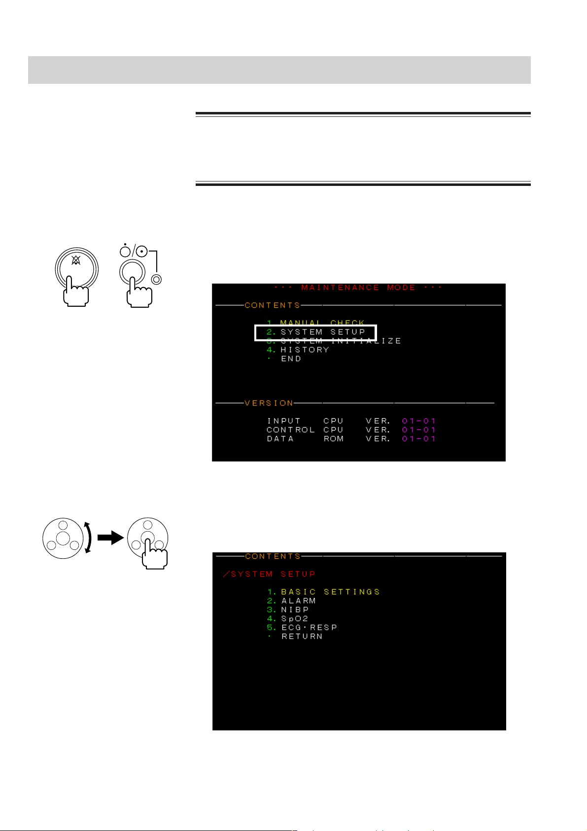
3. CHANGING SYSTEM SETUP SETTINGS
Displaying the SYSTEM SETUP Screen
This procedure interrupts all monitoring. Only change these settings
before or after monitoring.
1. Turn the monitor power off.
2. Press the power key while pressing the SILENCE ALARM key on the front
SILENCE
ALARM
+
panel until the MAINTENANCE MODE screen is displayed.
WARNING
3. Turn the rotary dial to select “2. SYSTEM SETUP” and press the rotary dial
center key. The SYSTEM SETUP screen appears.
3.2 Operator's Manual OPV-1500K
Page 66

3. CHANGING SYSTEM SETUP SETTINGS
Changing Settings 1. Select the desired setup item on the SYSTEM SETUP screen by turning the
rotary dial and pressing the rotary dial center key. A setup screen for that item
appears.
2. Select a setting item on the screen by turning the rotary dial and pressing the
rotary dial center key.
3. Turn the rotary dial to select the condition and press the rotary dial center key
to register the setting.
4. Select “RETURN” by turning the rotary dial and press the rotary dial center
key to return to the SYSTEM SETUP screen.
5. Repeat steps 1 to 4 to change other setup settings.
Closing the SYSTEM
SETUP Screen and
Displaying the Monitoring
Screen
1. After you change all desired settings, select “RETURN” on the SYSTEM
SETUP screen by turning the rotary dial and press the rotary dial center key.
The new settings are entered and the screen returns to the MAINTENANCE
MODE screen.
2. Select “END” by turning the rotary dial and press the rotary dial center key.
After a few seconds, the monitoring screen appears.
Operator's Manual OPV-1500K 3.3
Page 67

3. CHANGING SYSTEM SETUP SETTINGS
List and Explanation of the SYSTEM SETUP Settings
List of All Settings The factory default settings are underlined.
SETUP type Item Setting Conditions
BASIC
SETTINGS
ALARM
NIBP
ECG•RESP
1. LANGUAGE ENGLISH, JAPANESE
2. DATE FORMAT YYYY/MM/DD, MM-DD-YYYY, DD-MM-YYYY
3. LINE FREQUENCY 50 Hz, 60 Hz
4. REC DURATION 7.5, 15, 30, 60 s*
5. EXIT SLEEP MODE ON ALARM YES, NO
6. LIST SORTING NEWEST, OLDEST
7. BATTERY EXPIRATION ALERT OFF, ON, SET DATE
1. SAVE ALARM SETUP YES, NO
2. ALARM FREQUENCY (ADVISORY) 20, 40, 60, 120 s
3. ALARM LEVEL OF APNEA CRISIS, WARNING
1. NIBP MODE AFTER STAT
2. NIBP COMPLETED SOUND ON, OFF
3. DIM OLD NIBP DATA OFF, 10, 30, 60, 120, 180 min
4. PRESSURE UNIT mmHg, kPa
5. INIT CUFF PRESS (Adult mmHg) 120 to 240 mmHg, 180 mmHg
6. INIT CUFF PRESS (Adult kPa) 16.0 to 32.0 kPa, 24.0 kPa
7. INIT CUFF PRESS (Neo mmHg) 60 to 140 mmHg, 100 mmHg
8. INIT CUFF PRESS (Neo kPa) 8.0 to 18.0 kPa, 13.0 kPa
1. SpO2 RESPONSE FAST, NORMAL, SLOWSpO2
2. PROBE OFF DETECTION ON, OFF
1. PACING MARKER ON, OFF
2. SYNC SOUND PITCH LOW, HIGH
3. DRIFT FREE FILTER ON, OFF
4. AC LINE NOISE FILTER ON, OFF
5. HIGH CUT FILTER (40 Hz) ON, OFF
6. NOISE REDUCTION ON RESP ON, OFF
MANUAL, 2 min, 2.5 min, 5 min, 10 min, 15 min,
30 min
* These durations are when the recording speed is at 25 mm/s. The duration differs
according to the recording speed. The recording speed is set at REC SPEED on
the REC/SOUND window of the setup window.
3.4 Operator's Manual OPV-1500K
Page 68

BASIC SETTINGS
3. CHANGING SYSTEM SETUP SETTINGS
1. LANGUAGE: ENGLISH, JAPANESE
Select English or local language screen description.
2. DATE FORMAT: YYYY/MM/DD, MM-DD-YYYY, DD-MM-YYYY
Select date format.
YYYY: year, MM: month, DD: day
3. LINE FREQUENCY: 50 Hz, 60 Hz
Select line frequency of your area to reduce AC interference in SpO
monitoring.
2
NOTE
Make sure that the appropriate line frequency is selected. Otherwise,
noise may interfere on the pulse waveform.
4. REC DURATION: 7.5, 15, 30, 60 s
Select recording duration for manual recording. These durations are when the
recording speed is at 25 mm/s. When the recording speed is 12.5 mm/s, the
duration is doubled and when the recording speed is 6.25 mm/s, the duration is
four times that of 25 mm/s.
5. EXIT SLEEP MODE ON ALARM: YES, NO
YES: When an alarm occurs during sleep mode, the sleep mode is exited and the
monitoring screen appears.
NO: The sleep mode continues even when an alarm occurs.
WARNING
When EXIT SLEEP MODE ON ALARM is set to NO, the bedside monitor
alarm cannot be seen or heard on the bedside monitor during sleep
mode. Attach the transmitter (optional) to the monitor and monitor the
bedside monitor alarm on the central monitor or telemetry system.
Otherwise, bedside monitor alarms may be overlooked.
Operator's Manual OPV-1500K 3.5
Page 69

3. CHANGING SYSTEM SETUP SETTINGS
6. LIST SORTING: NEWEST, OLDEST
Select the list displaying order.
NEWEST: The latest data comes at the top.
OLDEST: The oldest data comes at the top.
7. BATTERY EXPIRATION ALERT: ON, OFF, SET DATE
An “INSERT NEW BATTERY” message can be displayed one year after installing
the new battery in the monitor.
To display the message, select “ON” and then select “SET DATE”. Today’s date is
displayed in the STATUS column at the lower part of the screen. The “INSERT
NEW BATTERY” message will be displayed one year after this date for 5 seconds
after turning on the monitor.
ALARM SETUP
1. SAVE ALARM SETUP: YES, NO
YES: Saves alarm settings after monitor power off.
NO: Alarm settings return to the initial settings 30 minutes after monitor power
off.
2. ALARM FREQUENCY (ADVISORY): 20, 40, 60, 120 s
Select the interval of the alarm sound (bongs) of the ADVISORY level alarm.
3. ALARM LEVEL OF APNEA: CRISIS, WARNING
Select the alarm level for the APNEA alarm.
3.6 Operator's Manual OPV-1500K
Page 70

NIBP SETUP
3. CHANGING SYSTEM SETUP SETTINGS
1. NIBP MODE AFTER STAT: MANUAL, 2, 2.5, 5, 10, 15, 30 min
The NIBP measurement mode after completing STAT (continuous) measurement
changes to the Manual mode or Auto mode with the selected interval.
2. NIBP COMPLETED SOUND: ON, OFF
ON: When NIBP measurement is completed, one “bong” sounds.
OFF: No sound.
3. DIM OLD NIBP DATA: OFF, 10, 30, 60, 120, 180 min
Select the duration time after NIBP measurement for the NIBP data to become dim.
When OFF is set, the NIBP data does not become dim.
4. PRESSURE UNIT: mmHg, kPa
Select the unit for NIBP.
5. INIT CUFF PRESS (Adult mmHg): 120 to 240 mmHg
6. INIT CUFF PRESS (Adult kPa): 16.0 to 32.0 kPa
Select the initial cuff inflation pressure for measuring an adult or child.
7. INIT CUFF PRESS (Neo mmHg): 60 to 140 mmHg
8. INIT CUFF PRESS (Neo kPa): 8.0 to 18.0 kPa
Select the initial cuff inflation pressure for measuring a neonate.
Operator's Manual OPV-1500K 3.7
Page 71

3. CHANGING SYSTEM SETUP SETTINGS
SpO2 SETUP
1. SpO2 RESPONSE: FAST, NORMAL, SLOW
Each response mode uses a different time to enable accurate measurements
according to patient conditions. When measurement condition is unstable,
response becomes slower in all modes.
FAST: Select this mode for special applications that require a fast response.
“FAST” is suitable for detecting short apnea.
NORMAL: For normal monitoring.
SLOW: Select this mode when you need to suppress a rapid change in SpO2.
2. PROBE OFF DETECTION: ON, OFF
ON: Detects probe off for SpO2 monitoring.
OFF: Does not detect probe off for SpO2 monitoring.
STATUS: SIGNAL LEVEL
The signal level shows the receiving current of the LED on the TL-201T finger
probe. Put the check board provided with the SpO2 connection cord between the
light emitter and photo detector of the probe. Replace the probe with a new one
when the signal level becomes half of the level at the first use. Use the table
attached at the end of this manual for writing the signal level. Refer to the service
manual for details.
R: red emitter, IR: infrared emitter
3.8 Operator's Manual OPV-1500K
Page 72

ECG/RESP SETUP
3. CHANGING SYSTEM SETUP SETTINGS
1. PACING MARKER: ON, OFF
When set to ON, the pacing mark can be displayed on the ECG.
2. SYNC SOUND PITCH: LOW, HIGH
High or low pitch synchronized sound can be selected.
3. DRIFT FREE FILTER: ON, OFF
When set to ON, this filter prevents ECG baseline drift.
4. AC LINE NOISE FILTER: ON, OFF
When set to ON, this filter reduces AC interference from the ECG.
5. HIGH CUT FILTER (40 Hz): ON, OFF
When set to ON, this filter removes noise from the ECG at 40 Hz.
6. NOISE REDUCTION ON RESP: ON, OFF
In the impedance method, noise from the heart beat may interfere on the respiration
waveform due to electrode position or when monitoring a neonate, and the
respiration rate may increase to almost the same rate as the heart rate. In such a
case, set this setting to ON to reduce noise interference on the respiration
waveform.
In normal monitoring of an adult, set this item to OFF. Otherwise, the respiration
rate may be miscounted.
NOTE
When this item is set to ON and the timing of the respiration and heart
beat coincide, respiration rate may not be counted. In such a case, set
this item to OFF or check the patient’s respiration by observing the
patient’s chest movement or the respiration waveform on the monitoring
screen.
Operator's Manual OPV-1500K 3.9
Page 73
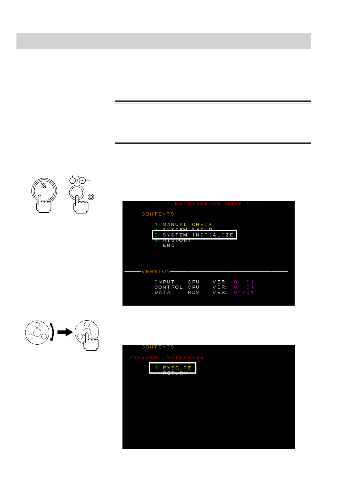
3. CHANGING SYSTEM SETUP SETTINGS
Initializing the System
Usually, this procedure is not performed. Use the following procedure to initialize
the monitor to the factory default settings. The factory default settings are listed in
the “Factory Default Settings” section.
All patient data, stored data and error history are deleted and all settings
return to the factory default settings.
1. If turned on, turn off the monitor power.
2. Press the power key while pressing the SILENCE ALARMS key on the front
SILENCE
ALARM
+
panel until the MAINTENANCE MODE screen is displayed.
CAUTION
3. Turn the rotary dial to select “3. SYSTEM INITIALIZE” and press the rotary
dial center key. The SYSTEM INITIALIZE screen is displayed.
3.10 Operator's Manual OPV-1500K
Page 74

3. CHANGING SYSTEM SETUP SETTINGS
4. Select “EXECUTE” and press the rotary dial center key to initialize the
settings.
When initializing is finished, the “OK” message appears.
To not initialize the settings or return to the MAINTENANCE MODE screen
after initialization, turn the rotary dial to select “RETURN” and press the
rotary dial center key.
When the monitor is initialized, the language setting is changed to JAPANESE.
Change the language to ENGLISH on “1. LANGUAGE” on the BASIC SETTINGS
screen of the SYSTEM SETUP screen.
Operator's Manual OPV-1500K 3.11
Page 75

3. CHANGING SYSTEM SETUP SETTINGS
Factory Default Settings
This section shows the available settings. The factory default settings are
underlined.
OK: Remains in memory even when the monitor is turned off.
30 min: Remains in memory for at least 30 minutes after turning the monitor off.
Refer to the “List and Explanation of the SYSTEM SETUP Settings” section.SYSTEM SETUP Screen
After 30 minutes, the setting changes back to the default setting.
ALARM Window
NIBP Window
Items Settings Backup
NIBP SYS (mmHg)
Adult/child
NIBP SYS (mmHg)
Neonate
NIBP SYS (kPa)
Adult/child
NIBP SYS (kPa)
Neonate
HR/PR (beats/min)
SpO2 (%)
RR (breaths/min)
APNEA (s) 5 to 40, OFF (5 steps), OFF
Items Settings Backup
INTERVAL (min) STAT, 1, 2, 2.5, 5, 10, 15, 30, 60, 120, 240 OK
ALARM MEAS ON, OFF
∆PWTT (ms) OFF, ±10 to 100 ms
Upper: 15 to 260, OFF (5 steps), 180
Lower: 10 to 255, OFF (5 steps), 80
Upper: 10 to 125, OFF (5 steps), 100
Lower: 5 to 120, OFF (5 steps), 50
Upper: 1.5 to 35.0, OFF (0.5 steps), 24.0
Lower: 1.0 to 34.5, OFF (0.5 steps), 10.5
Upper: 1.5 to 17.0, OFF (0.5 steps), 13.5
Lower: 1.0 to 16.5, OFF (0.5 steps), 5.5
Upper: 20 to 300, OFF (5 steps), 140
Lower: 15 to 295, OFF (5 steps), 40
Upper: 51 to 100, OFF (1 steps), OFF
Lower: 50 to 99, OFF (1 steps), 90
Upper: 2 to 150, OFF (2 steps), OFF
Lower: 0 to 148, OFF (2 steps), OFF
When SAVE
ALARM
SETUP on the
SYSTEM
SETUP screen
is set to:
YES: OK
NO: 30 min
30 min
3.12 Operator's Manual OPV-1500K
Page 76

3. CHANGING SYSTEM SETUP SETTINGS
ECG etc Window
REC/SOUND Window
Items Settings Backup
ECG SENS AUTO, ×1/4, ×1/2, ×1, ×2, ×4
ECG LEAD I, II, III
PACING DETECT ON, OFF
SpO2 SENS AUTO, ×1/8, ×1/4, ×1/2, ×1, ×2, ×4, ×8
SYNC SRCE AUTO, ECG, SpO2
SpO2 PITCH ON, OFF
RESP SENS OFF, ×1/4, ×1/2, ×1, ×2, ×4 30 min
Items Settings Backup
REC SPEED 6.25, 12.5, 25 mm/s
ALARM REC ON, OFF
AUTO LIST REC ON, OFF
ALARM (volume) 8 steps, 4
SYNC VOL 8 steps, 4
CLICK ON, OFF
30 min
OK
OK
OTHER Window
Items Settings Backup
1: AUTO/2: AUTO, 1: AUTO/2: OFF,
1: ECG/2: ECG, 1: ECG/2: SpO2,
WAVE DISP
LIST INTERVAL (min) OFF, 1, 5, 15, 30, 60
DELETE ALL YES, NO
Year 2001 to 2099
Month 01 to 12
Day 01 to 31
Hour 00 to 23
Minute 00 to 59
1: ECG/2: RESP, 1: SpO
1: ECG/2: OFF, 1: SpO
1: RESP/2: OFF, 1: OFF/2: OFF
2/2: RESP,
2/2: OFF
30 min
OK
Operator's Manual OPV-1500K 3.13
Page 77

Section 4 Alarm Function
Overview of Alarms .............................................................................................................4.2
What is an Alarm....................................................................................................... 4.2
Alarm Level ...............................................................................................................4.2
Alarm Priority ............................................................................................................ 4.2
Silencing an Alarm .................................................................................................... 4.3
Automatic Recording .................................................................................................4.3
Alarm Setting ............................................................................................................ 4.3
Adjusting Alarm Sound Volume .................................................................................4.3
Alarm Types ........................................................................................................................ 4.4
Vital Signs Alarms ....................................................................................................4.4
Parameter Alarms .....................................................................................................4.4
ECG/Respiration Related Alarms ....................................................................4.4
SpO2 Related Alarms ......................................................................................4.4
NIBP Related Alarms ......................................................................................4.5
Other Alarms ............................................................................................................. 4.5
Messages.................................................................................................................. 4.5
ECG Related Messages .................................................................................. 4.5
Respiration Related Messages........................................................................ 4.5
SpO2 Related Messages ................................................................................. 4.6
NIBP Related Messages .................................................................................4.6
Other Messages ............................................................................................. 4.6
Alarm Indications ................................................................................................................ 4.7
Overview ................................................................................................................... 4.7
Individual Alarm Indications ...................................................................................... 4.7
Vital Signs Alarms .......................................................................................... 4.7
Parameter Alarms ...........................................................................................4.8
Other Alarms................................................................................................... 4.9
Alarm Control Marks ................................................................................................. 4.9
Alarm Silence Mark ......................................................................................... 4.9
Individual Vital Signs Alarm Setting Indication ................................................ 4.9
Adjusting the Alarm Sound Volume ......................................................................... 4.10
Temporarily Silencing/Suspending Alarms .........................................................................4.11
Overview ................................................................................................................. 4.11
Silencing an Alarm After Alarm Occurrence ............................................................ 4.11
Operator's Manual OPV-1500K 4C.1
Page 78

Silencing an Alarm ........................................................................................ 4.11
Canceling an Alarm Silence .......................................................................... 4.12
Suspending an Alarm Before Alarm Occurrence ..................................................... 4.12
Turning Automatic Alarm Recording On/Off ....................................................................... 4.13
Setting Alarm .................................................................................................................... 4.15
Overview ................................................................................................................. 4.15
Alarm Limits Ranges ...............................................................................................4.15
Setting Vital Signs Alarm Limits ..............................................................................4.15
4C.2 Operator's Manual OPV-1500K
Page 79

4. ALARM FUNCTION
This section explains:
• An overview of alarms.
• Alarm types.
• Alarm indications.
• Silencing an alarm. When an alarm occurs, you can temporarily turn off the
alarm indications. This feature is useful if you are already attending to the
patient and don’t need the alarm.
• Setting individual alarms and turning automatic alarm recording on or off.
Operator's Manual OPV-1500K 4.1
Page 80
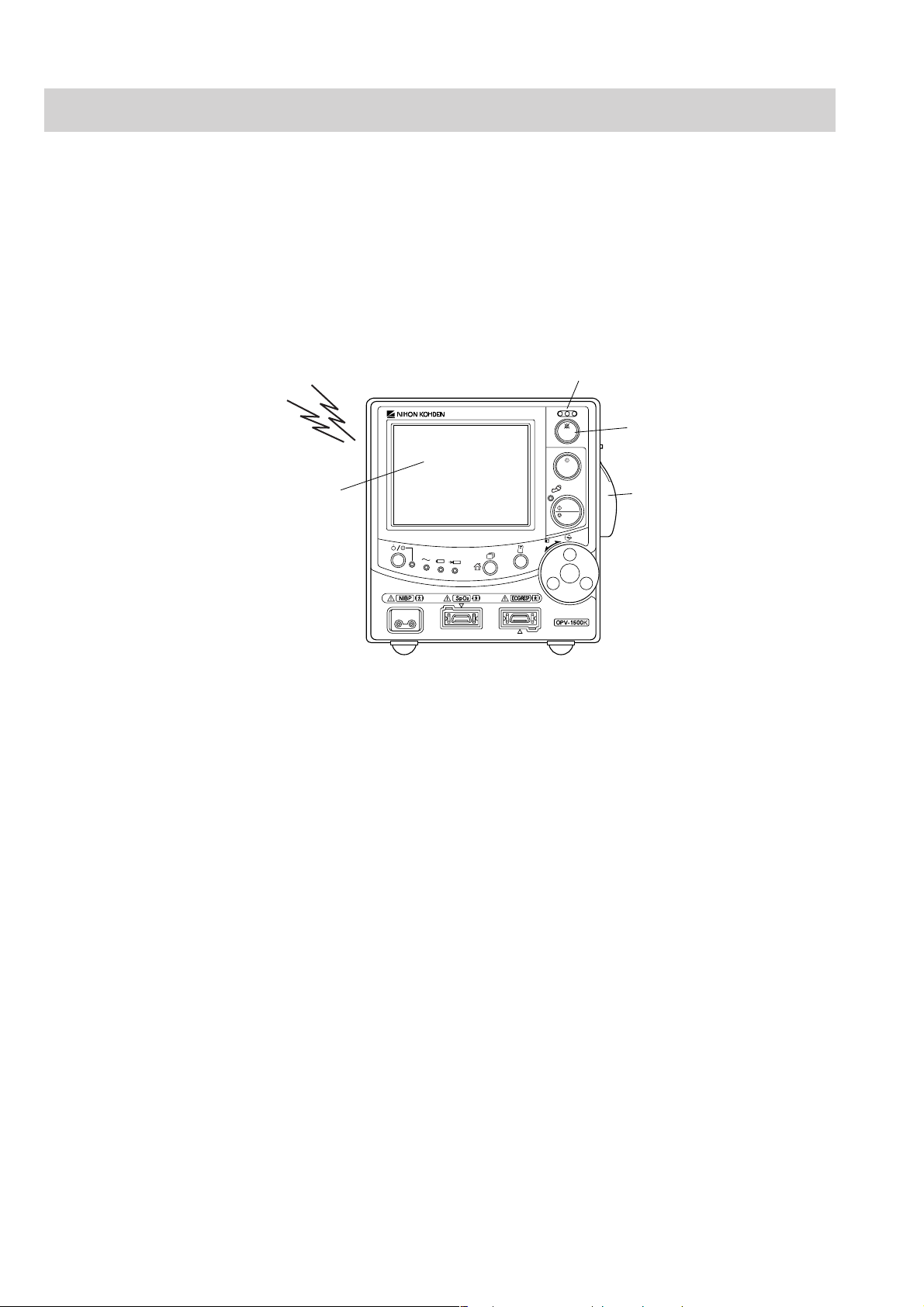
4. ALARM FUNCTION
Overview of Alarms
What is an Alarm
When the monitor detects an abnormal patient condition, it can generate an alarm
sound, screen indication, and alarm lamp indication. You can set each individual
alarm condition. There are three types of alarms: vital signs, parameter and other
alarms, and three levels of alarm: crisis, warning and advisory. The different alarm
types are fully explained in the “Alarm Types” section and different alarm levels
are explained in the “Alarm Indications” section.
Alarm sound
Alarm message
Alarm indicator
SILENCE
ALARM
INTERVAL
NIBP
START
STOP
MENU/SET
SELECT
SILENCE ALARM key
Alarm recording (when using
the optional recorder unit)
Alarm Level
Alarm Priority
There are three alarm levels.
CRISIS: Patient is in a critical condition and patient life may be at risk.
Immediate action must be taken.
WARNING: Patient is in a critical condition. Prompt action should be taken.
Electrodes or probe off, or incorrect lead or other cable connections
may also cause this alarm.
ADVISORY: Electrodes, probe, cuff, lead and other cable connections or settings
on the monitor are not appropriate for accurate measurement.
Prompt action should be taken.
When several alarms occur at the same time, the alarm with the highest alarm level
is indicated. When several alarms with the same alarm level occur at the same
time, the alarms are indicated one after another.
4.2 Operator’s Manual OPV-1500K
Page 81

4. ALARM FUNCTION
Silencing an Alarm
Automatic Recording
Alarm Setting
You can temporarily silence current alarm sounds and indications for a 2 minute
period. See the “Temporarily Silencing/Suspending Alarms” section.
WARNING
During alarm suspension, all current alarms are temporarily turned off.
With an optional RG-101W recorder unit, you can set the monitor to automatically
record waveforms and data when a vital sign alarm occurs. See the “Turning
Automatic Alarm Recording On/Off” section.
Usually, alarms are set before monitoring, but alarms can be set or changed
anytime without interrupting monitoring.
Adjusting Alarm Sound
Volume
When SAVE ALARM SETUP is set to YES on the SYSTEM SETUP screen, all
alarm settings are saved after monitor power off. When set to NO, all alarm
settings return to the factory default settings 30 minutes after monitor power off.
Refer to Section 3.
To set a vital sign alarm to off, set the upper and lower limits to OFF.
The alarm sound volume can be adjusted on the REC/SOUND window. At the
lowest setting, the alarm sound is still audible. Refer to the “Changing Alarm
Sound Volume” section.
Operator's Manual OPV-1500K 4.3
Page 82

4. ALARM FUNCTION
Alarm Types
Alarms are divided into 3 categories: vital signs, parameter and other alarms. The
alarm name is displayed on the screen when an alarm occurs. For the vital signs
alarms, waveforms and data can be recorded on the optional recorder unit in
automatic alarm recording.
Vital Signs Alarms
Heart rate/pulse rate alarm High/low limit exceeded
SpO2 alarm High/low limit exceeded
NIBP systolic alarm High/low limit exceeded (systolic)
Respiration rate alarm High/low limit exceeded
APNEA alarm Limit exceeded
Alarm Name Description
Parameter Alarms ECG/Respiration Related Alarms
Alarm Name Description
ECG CONNECTOR OFF
CHECK ELECTRODE Electrode loose or disconnected.
SpO2 Related Alarms
ECG connection cord is disconnected from the
ECG/RESP socket during monitoring.
Alarm Name Description
SpO2 PROBE FAULT SpO2 probe or connection cord is damaged.
SpO2 MODULE
FAILURE
SpO2 LIGHT
INTERFERENCE
SpO2 NO PROBE
SpO2 CHECK PROBE
SpO2 CANNOT
DETECT PULSE
4.4 Operator’s Manual OPV-1500K
SpO
2 hardware malfunction.
A surgical light, bilirubin lamp or sunlight is close to
the probe.
SpO
2 connection cord is disconnected from the SpO2
socket during monitoring.
Finger probe is not attached to the patient firmly or the
amount of transmitted light is too small to measure.
Pulse cannot be detected.
Page 83

4. ALARM FUNCTION
NIBP Related Alarms
Alarm Name Description
NIBP SAFETY VALVE
OPEN
NIBP CHECK
INTERVAL
NIBP HARDWARE
ERROR
NIBP NO PULSE
AIR HOSE OFF
CUFF OCCLUSION
AIR LEAK
SYSTOLIC OVER Systolic value is outside the measurable range.
NIBP MEAS TIME-OUT The measuring time exceeded the specified time.
Instrument automatically stopped inflating.
Auto measurement at 1 minute intervals is performed
for more than 30 minutes.
NIBP hardware malfunction.
Measurement cannot be performed because the
patient’s pulse wave is small, the cuff or hose leaks
air, the cuff hose is obstructed or the cuff is not
connected.
NIBP hose is disconnected from the cuff socket
during monitoring.
The cuff pressure does not decrease after
measurement has completed.
Cuff pressure does not change after inflation. The
cuff or air hose may be damaged.
Other Alarms
Messages
Alarm Name Description
LOW BATTERY Battery is getting weak.
The following messages are monitoring information and are not considered alarms.
ECG Related Messages
Message Description
ECG NOISE Too much noise on the ECG waveform.
Respiration Related Messages
Message Description
RESP NOISE Too much noise on the respiration waveform.
RESP OFF Respiration monitoring is turned off.
Operator's Manual OPV-1500K 4.5
Page 84

4. ALARM FUNCTION
SpO2 Related Messages
Message Description
SpO2 CHECK PROBE
SITE
SpO2 WEAK PULSE Poor peripheral circulation.
SpO2 SEARCHING
PULSE
M (highlighted) Pulse waveform is not stable.
The probe is not attached to the appropriate site or
the probe is damaged.
Auto gain control is being done. When the message
is displayed for more than 20 seconds, the detected
pulse is too small to measure.
NIBP Related Messages
Message Description
NIBP RE-MEASURING Remeasuring NIBP.
NIBP ZEROING NIBP zero balance adjustment is performed.
NIBP NOISE Noise detected during NIBP measurement.
NIBP WEAK PULSE Patient’s pulse is small.
INFLATION PRESS LOW Insufficient cuff inflation pressure.
HIGH CUFF PRESS Excessive pressure is applied by the cuff.
Other Messages
Message Description
OUT OF PAPER No recording paper.
RECORDER DOOR OPEN Recorder door is open.
4.6 Operator’s Manual OPV-1500K
Page 85

Alarm Indications
4. ALARM FUNCTION
Overview
Individual Alarm
Indications
The monitor can indicate alarms both visually and audibly.
• Alarm sound
• Alarm message or highlighted numeric data on the screen
• Alarm indicator: red or yellow lamp
Alarm control marks indicating that various alarm functions are turned off are also
displayed.
The alarm indicator indicates three alarm levels: crisis, warning and advisory. The
red or yellow lamp blinks according to the alarm level.
CRISIS: Red blinks
WARNING: Yellow blinks
ADVISORY: Yellow lit
Vital Signs Alarms
Alarm indication example
Alarm indication
The APNEA alarm level can be set to either CRISIS or WARNING on the
SYSTEM SETUP screen. Refer to Section 3.
Alarm
APNEA
HR/PR
2
SpO
NIBP SYS
RR
Operator's Manual OPV-1500K 4.7
Alarm
level
CRISIS
WA RN I N G
WA RN I N G
Alarm
sound
Continuous
“pips”
Continuous
“bing bongs”
Continuous
“bing bongs”
Alarm display
“APNEA” message
highlighted in red
“APNEA” message
highlighted in orange
Highlighted numeric data During detection Yellow
Sound/display
duration
During detection
Alarm
indicator LED
Red
Yellow
Page 86
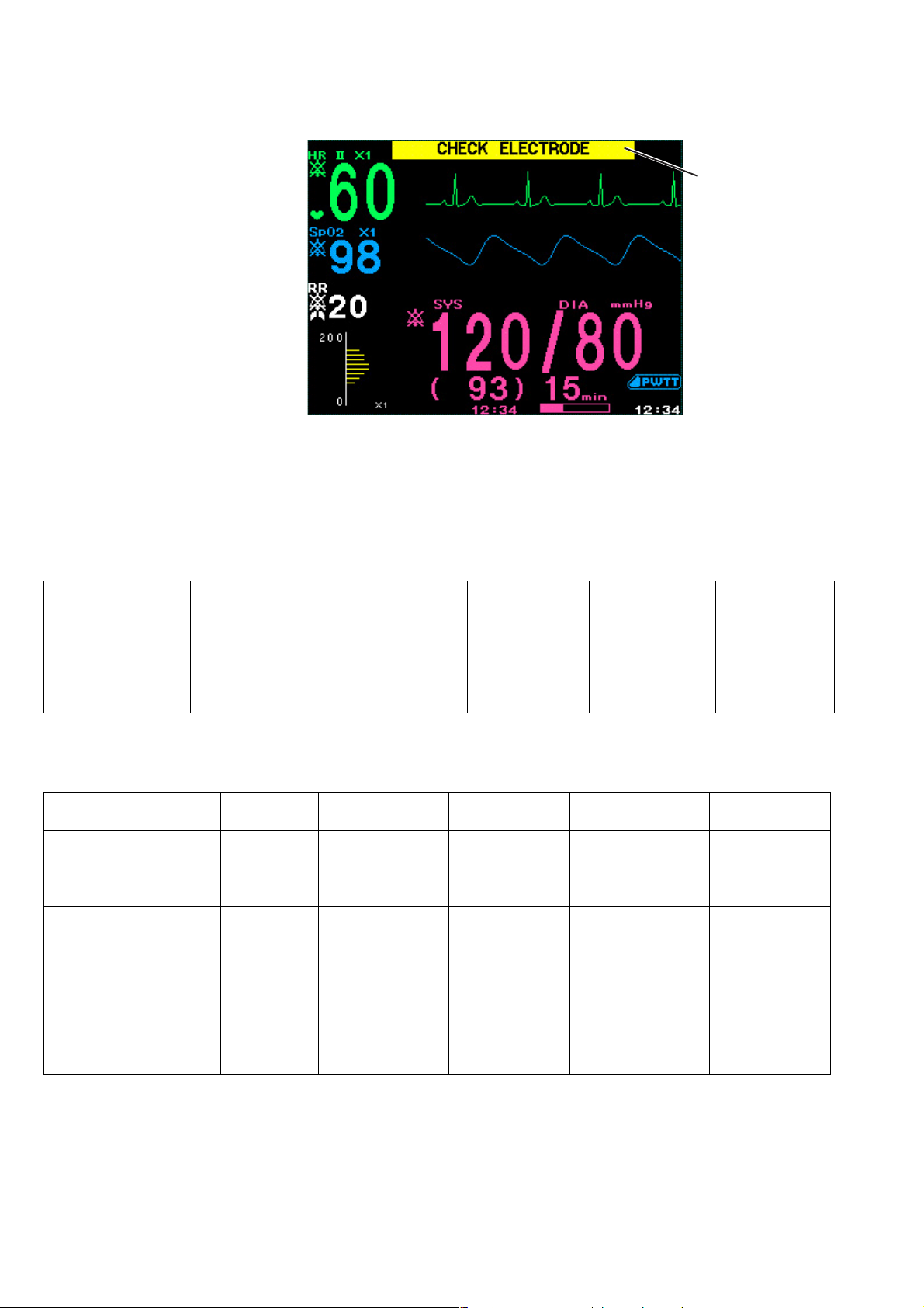
4. ALARM FUNCTION
Parameter Alarms
Alarm indication example
Alarm indication
ECG/Respiration related alarms
When the SILENCE ALARM key is pressed during these alarms, the alarm sound
and lamp indication stops and the heart rate or respiration rate data disappears from
the screen.
Alarm
CHECK
ELECTRODE
ECG CONNECTOR
OFF
Alarm Alarm level Alarm sound Alarm display
SpO2 PROBE FAULT
SpO
2 MODULE
FAI LU RE
SpO2 LIGHT
INTERFERENCE*
2 NO PROBE**
SpO
2 CHECK PROBE*
SpO
SpO
2 CANNOT
DETECT PULSE*
Alarm
level
ADVISORY
WA RN I NG
ADVISORY
Alarm sound Alarm display
One “bong” at an interval
set at ALARM
FREQUENCY
(ADVISORY) on the
Message
highlighted in
yellow
SYSTEM SETUP screen.
SpO2 related alarms
Continuous “bing
bongs”
Message
highlighted in
yellow
One “bong” at an
interval set at
ALARM
FREQUENCY
(ADVISORY) on
Message
highlighted in
yellow
the SYSTEM
SETUP screen.
Sound/display
duration
Alarm
indicator LED
During detection Yellow
Sound/
display duration
Alarm
indicator LED
During detection Yellow blinks
During detection Yellow lit
* When the SILENCE ALARM key is pressed during these alarms, the alarm sound and lamp indication stop and the
message color changes from highlighted yellow to white.
** When the SILENCE ALARM key is pressed during this alarm, the alarm sound and lamp indication stops and the SpO
numeric data disappears from the screen.
4.8 Operator’s Manual OPV-1500K
2
Page 87

4. ALARM FUNCTION
NIBP related alarms
Alarm Alarm level Alarm sound
NIBP SAFETY VALVE OPEN
NIBP CHECK INTERVAL
NIBP HARDWARE ERROR
One “bong” at an
NIBP NO PULSE*
AIR HOSE OFF**
CUFF OCCLUSION
AIR LEAK*
SYSTOLIC OVER*
NIBP MEAS TIME-OUT*
* When the SILENCE ALARM key is pressed during these alarms, the alarm sound and lamp indication stop and the
message disappears.
** When the SILENCE ALARM key is pressed during this alarm, the alarm sound and lamp indication stops and the NIBP
data disappears from the screen.
ADVISORY
interval set at
ALARM
FREQUENCY
(ADVISORY) on
the SYSTEM
SETUP screen.
Alarm
display
Message
highlighted
in yellow
Sound/display
duration
During detection Yellow lit
Alarm
indicator LED
Other Alarms
Alarm Alarm level Alarm sound Alarm display
LOW BATTERY WARNING
Alarm Control Marks
Continuous “bing
bongs”
When certain alarm functions are not available, an alarm control mark is displayed
on the screen.
Alarm Silence Mark
Remaining minutes is indicated beside the bell.
Message highlighted
in yellow
Sound/
display duration
During detection Yellow blinks
Alarm
indicator LED
Individual Vital Signs Alarm Setting Indication
The
vital signs alarm off mark is displayed at every parameter which has the
vital signs alarm limit set to OFF.
Operator's Manual OPV-1500K 4.9
Page 88

4. ALARM FUNCTION
Adjusting the Alarm Sound
Volume
The alarm sound volume can be adjusted on the REC/SOUND window. At the
lowest setting, the alarm sound is still audible.
1. From the monitoring screen, press the rotary dial center key on the front panel.
The ALARM window opens.
2. Turn the rotary dial to select “REC/SOUND” and press the rotary dial center
key to enter the REC/SOUND window. The cursor moves to the “REC
SPEED” box.
3. Turn the rotary dial to select “ALARM”, press the rotary dial center key to
change the cursor color to blue, turn the rotary dial to select the appropriate
alarm volume, and press the rotary dial center key to register the volume.
4. To return to the monitoring screen, select “CLOSE” on the REC/SOUND
window or press the HOME/REVIEW key on the front panel.
4.10 Operator’s Manual OPV-1500K
Page 89

Temporarily Silencing/Suspending Alarms
4. ALARM FUNCTION
Overview
Silencing an Alarm After
Alarm Occurrence
When an alarm occurs, you can silence the alarm sound and indications for two
minutes. When an alarm, except for NIBP systolic alarm, is silenced, the alarm
resumes after the alarm silence ends. When an NIBP systolic alarm is silenced, the
alarm sound and indication lamp do not resume after the alarm silence ends and
only the numeric data is highlighted. When several alarms occur together and the
SILENCE ALARM key is pressed, all alarms are silenced.
An alarm can also be suspended before it occurs, for example, before you replace
the electrodes. The alarm suspend time is two minutes.
During alarm silence,
• the suspended mark and the remaining minutes are displayed
• the alarm sound is silenced.
If another alarm occurs during alarm silence, the alarm sound, indication and
recording occur as usual. The alarm silence does not affect alarms which occur
after the SILENCE ALARM key is pressed. (A new occurrence of the silenced
alarm condition is treated as a different alarm.) When this alarm is silenced, the
alarm silence time is reset.
SILENCE
ALARM
Silencing an Alarm
Press the SILENCE ALARM key on the front panel. The alarm silenced mark
with the minutes remaining in the alarm silence are displayed on the screen.
The alarm silenced mark with the minutes remaining in the alarm silence
Operator's Manual OPV-1500K 4.11
Page 90

4. ALARM FUNCTION
Canceling an Alarm Silence
Vital sign alarm silence can be cancelled by pressing the
key. The alarm silence mark disappears and all alarms are resumed. Parameter
alarm and other alarm silence cannot be cancelled.
SILENCE ALARM
Suspending an Alarm
Before Alarm Occurrence
During alarm suspension, all alarms are suspended and
• the alarm silenced mark with the remaining suspension time is displayed
• the alarm sound is silenced.
The alarm suspend time is 2 minutes.
WARNING
All alarms are suspended during two minutes alarm suspension.
4.12 Operator’s Manual OPV-1500K
Page 91
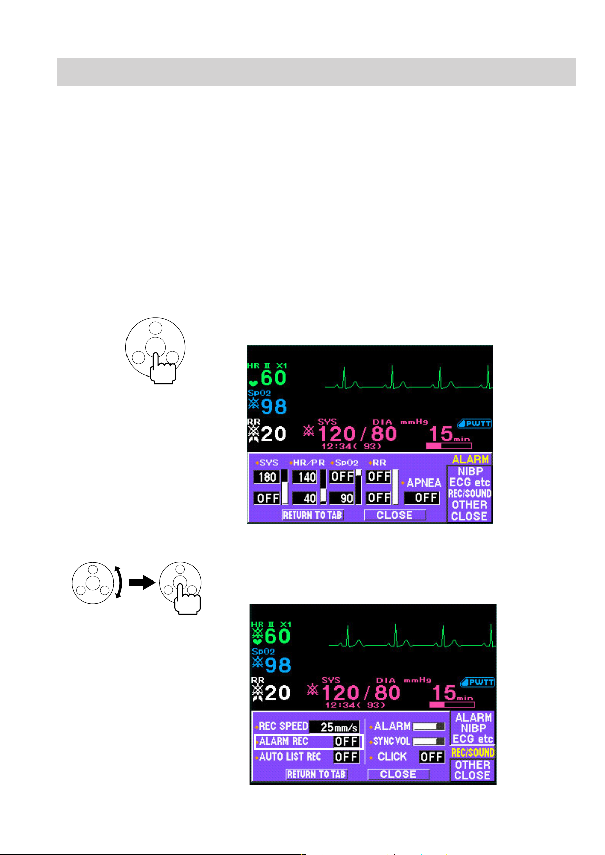
Turning Automatic Alarm Recording On/Off
Alarm recording is available only when the optional RG-101W recorder unit is
installed in the monitor.
If ALARM REC on the REC/SOUND window is set to ON, monitoring waveforms
beginning 4 seconds before and ending 11 seconds after the alarm are
automatically recorded with numeric data at 25 mm/s recording speed when a vital
sign alarm is generated. If this setting is OFF, the data are not automatically
recorded when an alarm occurs. You can still record data manually.
To cancel recording while an automatic vital signs alarm is being recorded, press
the record key on the front panel.
To set automatic vital signs alarm recording on or off:
1. From the monitoring screen, press the rotary dial center key on the front panel.
The ALARM window opens.
4. ALARM FUNCTION
2. Turn the rotary dial to select “REC/SOUND” and press the rotary dial center
key to enter the REC/SOUND window. The cursor moves to the “REC
SPEED” box.
Operator's Manual OPV-1500K 4.13
Page 92

4. ALARM FUNCTION
3. Turn the rotary dial to select “ALARM REC” and press the rotary dial center
key to select ON or OFF.
4. To return to the monitoring screen, select “CLOSE” on the REC/SOUND
window or press the HOME/REVIEW key on the front panel.
4.14 Operator’s Manual OPV-1500K
Page 93

Setting Alarm
4. ALARM FUNCTION
Overview
Alarm Limits Ranges
Parameter Upper limit (Default setting) Lower limit (Default setting) Step
NIBP adult
(mmHg/kPa)*
NIBP neonate
(mmHg/kPa)*
HR/PR (beats/min) 20 to 300, OFF (140) OFF, 15 to 295 (40) 5
SpO2 (%) 51 to 100, OFF (OFF) OFF, 50 to 99 (90) 1
RR (breaths/min) 2 to 150, OFF (OFF) OFF, 0 to 148 (OFF) 2
Apnea (s) 5 to 40, OFF (OFF) 5
15 to 260, OFF (180) mmHg
1.5 to 35.0, OFF (24.0) kPa
10 to 125, OFF (100) mmHg
1.5 to 17.0, OFF (13.5) kPa
Set all alarm limits on the ALARM window.
When SAVE ALARM SETUP on the SYSTEM SETUP screen is set to:
ON: The alarm setting remains in memory after power off.
OFF: The alarm setting returns to the factory default settings 30 minutes after the
monitor power off. The red diamond marks are displayed in front of the
parameter label on the ALARM window.
To set NIBP alarm limits for neonate, the cuff for neonates must be connected to
the cuff socket on the monitor.
The following table shows the setting ranges for each alarm. Any upper and lower
limit can also be set to off.
OFF, 10 to 255 (80) mmHg
OFF, 1.0 to 34.5 (10.5) kPa
OFF, 5 to 120 (50) mmHg
OFF, 1.0 to 16.5 (5.5) kPa
5 mmHg
5 mmHg
0.5 kPa
0.5 kPa
* The NIBP unit can set on the SYSTEM SETUP screen. Refer to Section 3.
Setting Vital Signs Alarm
Limits
When the alarm limit is set to OFF, there will be no alarm for that limit.
If the upper limit is set to a value above the maximum, or the lower limit is set to a
value below the minimum, the alarm for that upper/lower limit is automatically set
to OFF.
1. From the monitoring screen, press the rotary dial center key on the front panel.
The ALARM window opens.
CAUTION
Operator's Manual OPV-1500K 4.15
Page 94

4. ALARM FUNCTION
Upper limit
Lower limit
2. Press the rotary dial center key to enter the ALARM window. The cursor
moves to the “SYS” upper box.
3. Press the rotary dial center key to change the cursor color to blue, turn the
rotary dial to select the limit for that parameter, and press the rotary dial center
key to register the setting.
4. To set an alarm for another parameter, turn the rotary dial to move the cursor to
that limit box, press the rotary dial center key to change the cursor color to
blue, turn the rotary dial to select the limit for that parameter, and press the
rotary dial center key to register the setting.
5. To return to the monitoring screen, select “CLOSE” on the REC/SOUND
window or press the HOME/REVIEW key on the front panel.
4.16 Operator’s Manual OPV-1500K
Page 95

Section 5 Monitoring Screen and
Review Windows
Safety Precautions for Monitoring ....................................................................................... 5.2
Using an Electrosurgery Unit ..........................................................................5.2
Using a Defibrillator .........................................................................................5.2
Overview ............................................................................................................................. 5.3
Monitoring Screen ..................................................................................................... 5.3
Review Windows ....................................................................................................... 5.3
Sync Sound .............................................................................................................. 5.3
Adjusting the Sync Sound Volume ............................................................................5.3
Changing Settings and Performing Other Tasks During Monitoring ............................5.3
Monitoring Screen ...............................................................................................................5.4
Changing Displayed Waveforms on the Monitoring Screen ........................................5.5
Using Sleep Mode ............................................................................................................... 5.7
Turning Sleep Mode On ...................................................................................5.7
Turning Sleep Mode Off................................................................................... 5.8
List Window ......................................................................................................................... 5.9
Overview ................................................................................................................... 5.9
Displaying the List Window ........................................................................................ 5.9
MEMO .......................................................................................................... 5.10
Setting the Data Sampling Interval .......................................................................... 5.10
Recording the List ................................................................................................... 5.11
Recording the Displayed or All List Data ....................................................... 5.11
Auto List Recording ....................................................................................... 5.13
Trendgraph Window ............................................................................................................ 5.14
Overview ................................................................................................................. 5.14
Displaying the Trendgraph Window........................................................................... 5.14
Scrolling the Trendgraph ................................................................................ 5.15
Changing the Trendgraph Time Width .............................................................5.15
Changing the Trendgraph Scale ..................................................................... 5.16
Recording the Trendgraphs ...................................................................................... 5.16
Operator's Manual OPV-1500K 5C.1
Page 96

5. MONITORING SCREEN AND REVIEW WINDOWS
This section explains how to monitor the patient’s waveforms and data.
Before monitoring the patient:
• Prepare the patient and equipment according to Sections 2 to 4, 7 to 10. When
using a recorder unit, also see Section 6.
• Before monitoring a new patient, follow the flowchart in Section 2.
• Read the safety precautions in the “Safety Precautions for Monitoring” section.
In this section:
• “Overview” gives general information for all monitoring.
• “Using Sleep Mode” explains how to use sleep mode.
• “List Window” and “Trendgraph Window” sections explain about the list
window and trendgraph window, respectively.
Operator's Manual OPV-1500K 5.1
Page 97

5. MONITORING SCREEN AND REVIEW WINDOWS
Safety Precautions for Monitoring
Before beginning monitoring, observe the following safety precautions and the
safety precautions in Sections 7 to 10 for ECG and other monitored parameters.
Using an Electrosurgery Unit
••
• Electrosurgical units (ESU) emit a lot of RF interference. If the
••
monitor is used with an ESU, RF interference may affect the monitor
operation.
••
• Locate the monitor as far as possible from the ESU. Locate them on
••
opposite sides of the operating table, if possible.
••
• Connect the monitor and ESU to different AC outlets located as far
••
as possible from each other.
••
• When using this monitor with an electrosurgical unit, its return plate
••
and the electrodes for monitoring must be firmly attached to the
patient. If the return plate is not attached correctly, it may burn the
patient’s skin where the electrodes are attached.
WARNING
Using a Defibrillator
WARNING
To avoid the risk of serious electrical burn, shock, or other injury
during defibrillation, all persons must keep clear of the bed and must
not touch the patient or any equipment connected to the patient.
If the ECG waveform on the screen is too unstable to synchronize with the patient’s
heart beat because of the following reason(s), remove the cause(s) of an alarm,
message, or unstable ECG, and then use a stable ECG lead for synchronization.
• ECG electrode is detached or broken. Lead wire is detached or broken.
• Lead wire moves. AC interference, EMG noise or noise from ESU is
superimposed.
• Connection cable is broken or has a short circuit. Connector has poor
contact.
5.2 Operator’s Manual OPV-1500K
Page 98

Overview
5. MONITORING SCREEN AND REVIEW WINDOWS
Monitoring Screen
Review Windows
When you first begin monitoring, a monitoring screen appears. The monitoring
screen displays waveforms and numeric data for monitoring parameters. Any time
you press the HOME/REVIEW key on the front panel, the monitoring screen
appears.
The parameters on the monitoring screen depend on the measured parameters.
NOTE
The stored data remains in memory for about 30 minutes after the
monitor power is turned off. After 30 minutes, the stored data is lost.
The list and trendgraph windows display the stored data. You can display the list of
up to 400 vital signs data on the list window and a trendgraph with 30 min, 1, 2, 4,
8 or 24 hour trend time on the trendgraph window.
For details about the review windows, refer to the “List Window” and “Trendgraph
Window” sections.
Sync Sound
Adjusting the Sync Sound
Volume
Changing Settings and
Performing Other Tasks
During Monitoring
During monitoring, a continuous “pip” sounds in synchronization with either the
QRS or SpO2 pulse. QRS is the default setting. Refer to “Changing the Sync
Source” in Section 7 or 9 to change the source of the sync sound.
The sync sound volume can be adjusted on the REC/SOUND window. At the
lowest setting, the sync sound is not audible. Refer to the “Changing the Sync
Sound Volume” section.
Every screen except the SYSTEM SETUP screen always displays the monitoring
parameter data. This lets you monitor the patient continuously without interruption
while you do other tasks, such as changing settings, recording or viewing
trendgraphs.
Operator's Manual OPV-1500K 5.3
Page 99
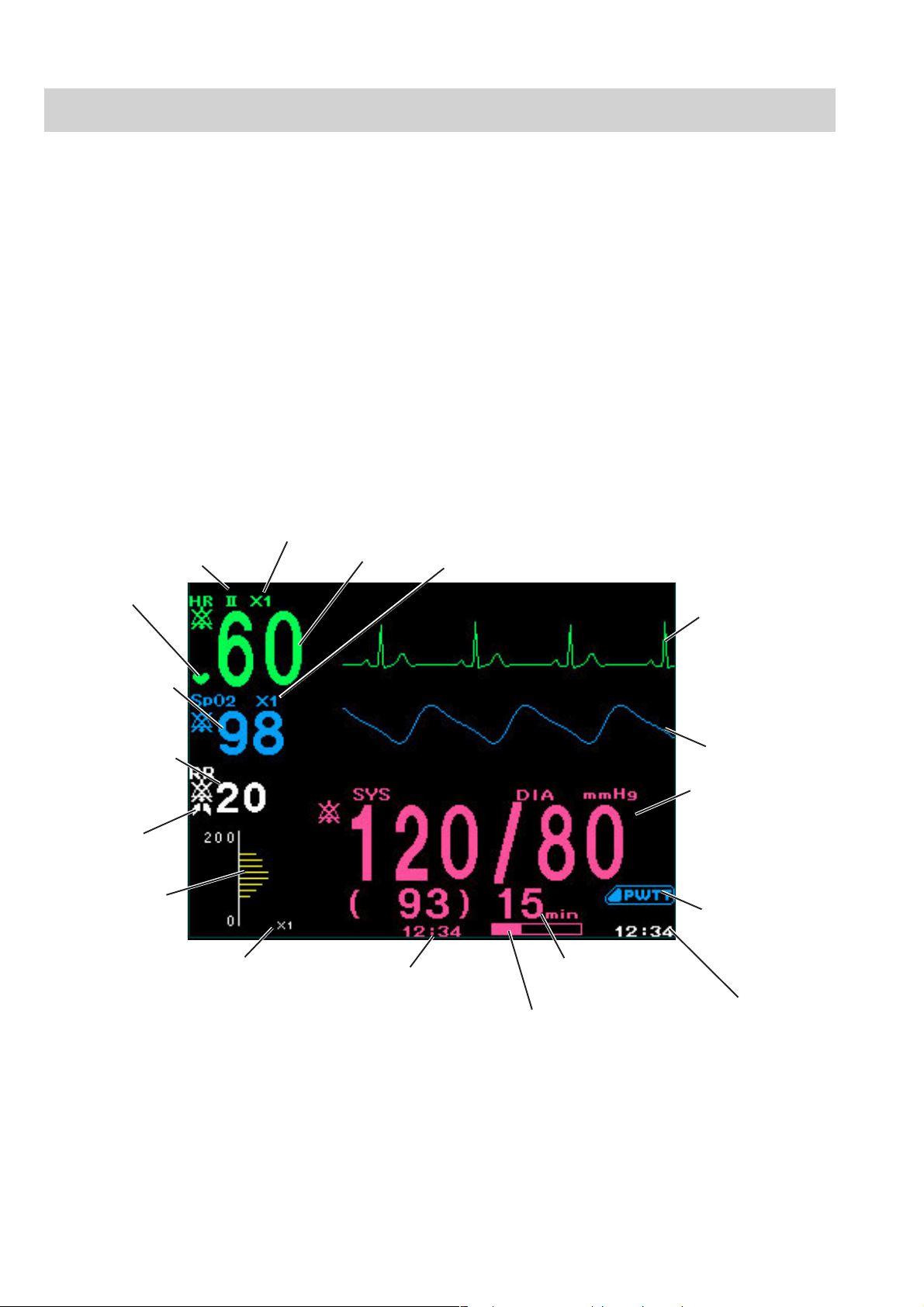
5. MONITORING SCREEN AND REVIEW WINDOWS
Monitoring Screen
When you first begin monitoring, a monitoring screen appears.
The monitoring screen is automatically laid out according to the measured
parameters. The layout changes when a parameter connection cord is connected or
disconnected.
The settings for monitoring parameters can be changed on the setup windows. For
details about individual parameters, see Sections 7 to 10.
Up to two waveforms can be displayed on the monitoring screen. To select the
displayed waveforms, refer to the “Changing Displayed Waveforms on the
Monitoring Screen” section.
QRS sync mark
SpO
Respiration rate
Respiration
sync mark
NIBP oscillation
graph
Oscillation sensitivity
is set from ×1/5, ×1,
and ×5 automatically
ECG lead
2
When monitoring ECG, impedance respiration, SpO
ECG sensitivity
Heart rate
NIBP measurement time
SpO2 sensitivity
NIBP measurement
mode
Time bar indicating remaining
time until the next NIBP
measurement
and NIBP
2
ECG
SpO2 pulse
waveform
NIBP SYS/DIAS
(MEAN)
Displayed when
delta PWTT is set
to a threshold
Current time
The size of the NIBP display depends on the number of displayed waveforms.
5.4 Operator’s Manual OPV-1500K
Page 100
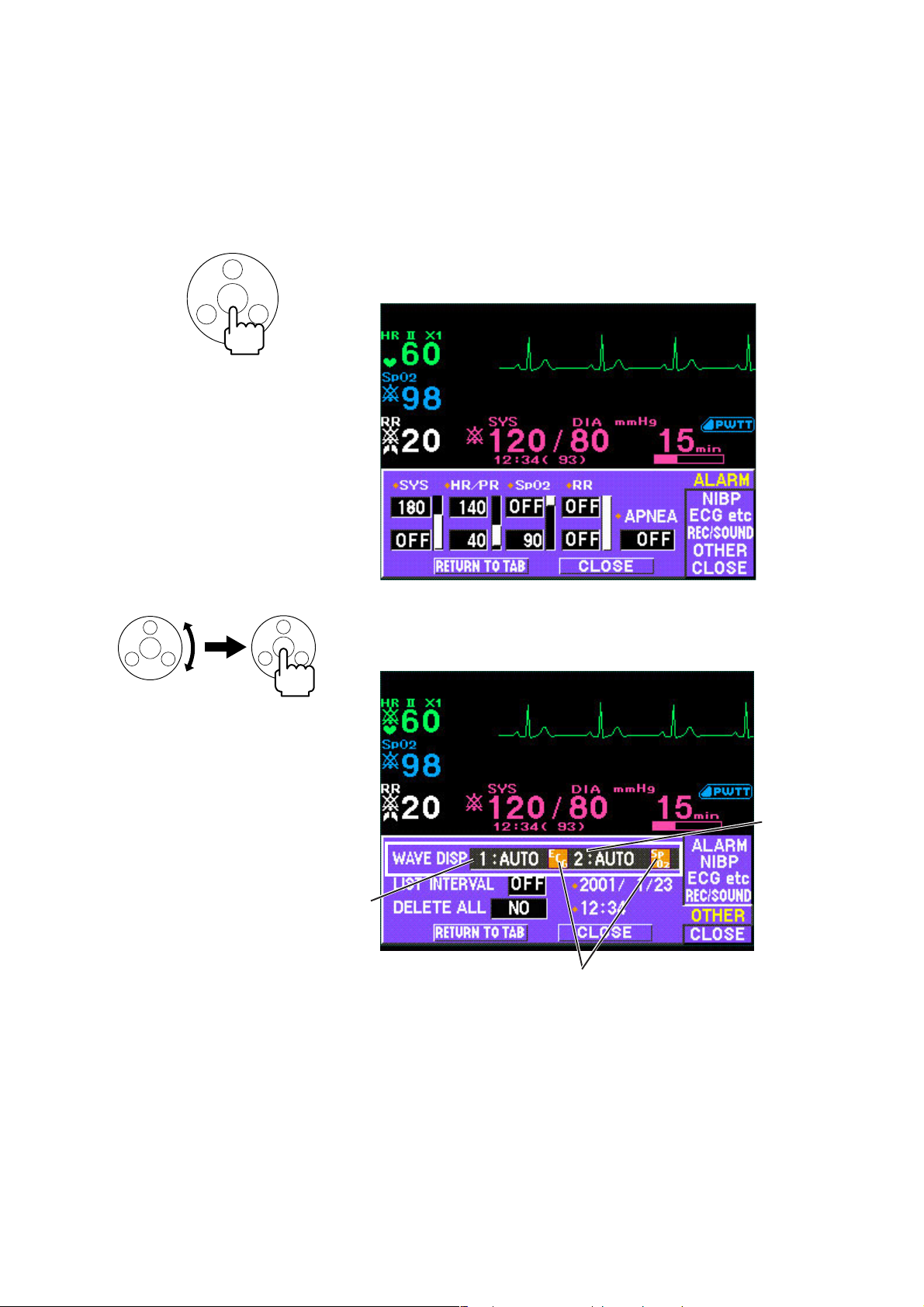
5. MONITORING SCREEN AND REVIEW WINDOWS
Changing Displayed
Waveforms on the
Monitoring Screen
Up to two waveforms can be displayed on the monitoring screen. The displayed
waveforms can be changed on the OTHER window of the setup window.
When a setup window or review window is displayed, only the waveform set for
the upper wave is displayed on the screen.
To change the displayed waveform parameters:
1. From the monitoring screen, press the rotary dial center key on the front panel.
The ALARM window opens.
2. Turn the rotary dial to select “OTHER” and press the rotary dial center key to
Upper wave
3. Press the rotary dial center key to change the cursor color to blue and turn the
enter the OTHER window. The cursor moves to the “WAVE DISP” box.
Lower wave
Currently displayed parameter
rotary dial to select waveforms. The parameters change in the following order.
1: AUTO/2: AUTO → 1: AUTO/2: OFF → 1: ECG/2: ECG → 1: ECG/2: SpO2
→ 1: ECG/2: RESP → 1: SpO2/2: RESP → 1: ECG/2: OFF → 1: SpO2/2: OFF
→ 1: RESP/2: OFF → 1: OFF/2: OFF
When “AUTO” is selected, the actual waveform is selected in the following
priority.
ECG > SpO2 > RESP
Operator's Manual OPV-1500K 5.5
 Loading...