

Page 1

User’s Guide
Part I
Bedside Monitor
BSM-6301/BSM-6501/BSM-6701
BSM-6000 series
BSM-6301A
BSM-6301K
BSM-6501A
BSM-6501K
BSM-6701A
BSM-6701K
0614-900676G
Page 2

If you have any comments or suggestions on this manual, please contact us at: www.nihonkohden.com
Copyright Notice
The entire contents of this manual are copyrighted by Nihon Kohden. All rights are reserved. No part of this document
may be reproduced, stored, or transmitted in any form or by any means (electronic, mechanical, photocopied, recorded,
or otherwise) without the prior written permission of Nihon Kohden.
Trademark
The mark printed on the SD card that is used in this instrument is a trademark. The company name and model name are
trademarks and registered trademarks of each company.
Page 3

Contents
1
2
GENERAL HANDLING PRECAUTIONS ............................................................................. i
WARRANTY POLICY ......................................................................................................... ii
EMC RELATED CAUTION .................................................................................................iii
Conventions Used in this Manual and Instrument ............................................................ vi
Warnings, Cautions and Notes ............................................................................... vi
Text Conventions in this Manual .............................................................................. vi
Explanations of the Symbols in this Manual and Instrument ............................................vii
Related Documentation ..................................................................................................... xi
Safety Standards .............................................................................................................. xi
Safety Information .............................................................................................................. xi
Section 1 General ................................................................................... 1.1
Introduction ...................................................................................................................... 1.3
General .................................................................................................................. 1.3
Applications ................................................................................................. 1.4
Features ...................................................................................................... 1.4
Measurement Parameters, and Applicable Units ........................................1.6
Composition ..................................................................................................................... 1.8
Network Composition ....................................................................................................... 1.9
Panel Description ...........................................................................................................1.10
MU-631R Main Unit ............................................................................................. 1.10
Front Panel ................................................................................................ 1.10
Left Side Panel .......................................................................................... 1.11
Right Side Panel ........................................................................................1.11
Rear Panel ................................................................................................. 1.12
MU-651R/MU-671R Main Unit ............................................................................. 1.13
Front Panel ................................................................................................ 1.13
Left Side Panel .......................................................................................... 1.14
Right Side Panel ........................................................................................1.14
Rear Panel ................................................................................................. 1.15
AY-631P/633P/651P/653P/660P/661P/663P/671P/673P Input Unit.................... 1.16
Front Panel ................................................................................................ 1.16
Using MULTI Sockets for CO Monitoring ................................................... 1.16
Using the Output Signal from the ECG/BP OUT Socket ........................... 1.17
Left Side Panel .......................................................................................... 1.18
Right Side Panel ........................................................................................1.18
Rear Panel ................................................................................................. 1.19
AA-672P/AA-674P Smart Expansion Unit ........................................................... 1.19
Front Panel ................................................................................................ 1.19
Using MULTI Sockets for CO Monitoring ................................................... 1.20
Right Side Panel ........................................................................................1.20
QF series Interface and IF series Communication Cable .................................... 1.21
RY-910PA Remote Controller ...............................................................................1.22
Basic Operating Concepts ............................................................................................. 1.23
3
4
5
6
7
8
9
10
11
User’s Guide Part I BSM-6000 C.1
Page 4

C.2 User’s Guide Part I BSM-6000
CONTENTS
Screen Displays ...................................................................................................1.23
Using Touch Screen Keys ...................................................................................1.29
Keys on the Bedside Monitor ...............................................................................1.30
Using the Remote Control ................................................................................... 1.31
Using the Mouse ..................................................................................................1.31
Using the Data Acquisition Unit ........................................................................... 1.32
Using the MENU Window .................................................................................... 1.33
Transport Function ......................................................................................................... 1.34
Overview ..............................................................................................................1.34
Requirements ...................................................................................................... 1.34
Necessary Settings Before Use ........................................................................... 1.34
Transported Data and Settings ............................................................................ 1.35
Sending Data to a CNS-9701 Central Monitor.....................................................1.36
Patient Authentication .......................................................................................... 1.37
Preparing for Removing the Input Unit ................................................................ 1.41
Enabling the Input Unit ........................................................................................ 1.42
When the Input Unit is Disabled ................................................................ 1.42
Enabling the Input Unit .............................................................................. 1.42
Section 2 Preparation ............................................................................ 2.1
Preparation Flowchart ......................................................................................................2.2
Installation Conditions ......................................................................................................2.3
Inserting and Removing the Battery Pack .......................................................................2.5
Battery Handling and Operation ............................................................................ 2.5
Safety Information ....................................................................................... 2.5
Battery Pack Handling Procedures .............................................................. 2.6
When Not Using the Monitor or Battery Pack .............................................. 2.6
Inserting and Removing the Battery Packs ...........................................................2.6
Inserting the Battery Pack .....................................................................................2.7
Removing the Battery Pack ................................................................................... 2.8
Inserting and Removing the Input Unit ...........................................................................2.9
Inserting the Input Unit ..........................................................................................2.9
Removing the Input Unit ........................................................................................ 2.9
When the Transport Function is Enabled ................................................... 2.10
Preparing the Optional Recorder ................................................................................... 2.11
Installing the Recorder Module ............................................................................ 2.11
Loading Recording Paper .................................................................................... 2.11
Preparing the Remote Control ....................................................................................... 2.13
Installing the Batteries ......................................................................................... 2.13
Setting the Remote Control Channel ................................................................... 2.14
Attaching the Remote Control Channel Label to the Bedside Monitor ................ 2.14
Assigning Functions to the Customized Keys ...................................................... 2.14
Power ............................................................................................................................. 2.15
Connecting the Power Cord and Grounding the Monitor ..................................... 2.15
Connecting the Power Cord .......................................................................2.15
Grounding the Monitor ...............................................................................2.16
Turning the Power On .......................................................................................... 2.16
Check Before Turning On the Power .........................................................2.16
Page 5

CONTENTS
Turning the Power On ................................................................................ 2.17
AUTO ADMIT Setting ................................................................................2.18
Check After Turning On the Power and During Monitoring ........................ 2.18
Power and Battery Status Indications .................................................................. 2.19
When the “BATTERY WEAK” Message Appears ......................................2.20
Charging the Battery Pack ......................................................................... 2.20
Monitor Status on Power Interruption ..................................................................2.21
Turning the Power Off .......................................................................................... 2.22
Check After/Before Turning the Power Off ................................................. 2.22
Section 3 Necessary Settings Before Monitoring ...............................3.1
Changing Date and Time ................................................................................................. 3.2
Changing Sound Volume Settings ...................................................................................3.3
Changing the Screen Brightness ..................................................................................... 3.4
Changing Waveform Display Settings .............................................................................. 3.5
Entering Patient Information ............................................................................................ 3.7
Displaying the PATIENT INFO Page ...................................................................... 3.8
Closing the PATIENT INFO Page ..........................................................................3.8
Entering the Patient Information ............................................................................ 3.9
Entering the Patient ID ................................................................................ 3.9
Entering the Patient Name ........................................................................ 3.10
Entering the Date of Birth and Age ........................................................... 3.11
Entering the Height and Weight ................................................................. 3.13
Entering the Gender .................................................................................. 3.13
Entering the Pacemaker Use ..................................................................... 3.14
Deleting Data ................................................................................................................. 3.16
Suspended Alarms after Deleting Data ..................................................... 3.18
1
2
3
4
5
6
7
8
9
10
11
Section 4 Home Screen ......................................................................... 4.1
Safety Precautions for Monitoring .................................................................................... 4.3
Using an Electrosurgical Unit ...................................................................... 4.3
Using a Defibrillator ..................................................................................... 4.3
Overview .......................................................................................................................... 4.4
Home Screen .........................................................................................................4.4
Review Windows ....................................................................................................4.4
Sync Sound ........................................................................................................... 4.4
Adjusting the Sync and Alarm Sound Volume .......................................................4.4
Changing Settings and Performing Other Tasks During Monitoring ...................... 4.4
Site Mode ..............................................................................................................4.5
Recording/Printing on the Home Screen ............................................................... 4.5
Interbed Monitoring ................................................................................................4.5
Home Screen ................................................................................................................... 4.6
Settings for the Home Screen ............................................................................... 4.7
Waveform Sweep Mode and Speed ............................................................ 4.7
Waveform Display on the Home Screen ......................................................4.7
Pacing Mark Position on the ECG Waveform .............................................. 4.7
User’s Guide Part I BSM-6000 C.3
Page 6

C.4 User’s Guide Part I BSM-6000
CONTENTS
ST Waveform and Reference ST Recall Waveform Display on the
Home Screen On or Off ............................................................................... 4.7
Blood Pressure Waveform Display Mode .................................................... 4.7
PPV or SPV Display on the Home Screen .................................................. 4.8
Pulse Rate Display on the Home Screen .................................................... 4.8
Current Average CO and PCWP Values Display on the Home Screen ....... 4.8
Trendgraph/PWTT Trendgraph/OCRG Display on the Home Screen On
or Off ...........................................................................................................4.8
Scale Setting for the Trendgraph on the Home Screen ...............................4.9
Parameter Colors ........................................................................................ 4.9
Waveform Sensitivity ................................................................................... 4.9
Displaying Other Windows from the Home Screen ..............................................4.10
Displaying PWTT Trendgraph ........................................................................................4.11
Displaying OCRG ........................................................................................................... 4.13
Freezing Waveforms ...................................................................................................... 4.14
Using Sleep Mode .........................................................................................................4.15
Turning Sleep Mode On ............................................................................. 4.15
Turning Sleep Mode Off ............................................................................. 4.16
Displaying the LARGE NUMERICS Screen ................................................................... 4.17
Section 5 Alarm Function ...................................................................... 5.1
Overview of Alarms .......................................................................................................... 5.4
What is an Alarm ................................................................................................... 5.4
Alarm Level ............................................................................................................5.5
Alarm Priority ......................................................................................................... 5.5
Alarm Sound/Alarm Indicator ......................................................................5.5
Alarm Messages on the Screen .................................................................. 5.5
Silencing/Suspending Alarms ................................................................................ 5.5
Alarm Master ......................................................................................................... 5.6
Automatic Recording ............................................................................................. 5.7
Alarm Setting ......................................................................................................... 5.7
Canceling the Technical Alarm ..............................................................................5.8
Adjusting Alarm Sound Volume .............................................................................5.8
Alarm Activation after Power On ............................................................................ 5.8
ALARM HISTORY Window .................................................................................... 5.8
Interbed Alarm ....................................................................................................... 5.9
Alarm Types ................................................................................................................... 5.10
Vital Signs Alarms ...............................................................................................5.10
Arrhythmia Alarms ............................................................................................... 5.10
Technical Alarms ................................................................................................. 5.11
ECG Related Alarms ................................................................................. 5.11
Respiration Related Alarms ....................................................................... 5.11
CO2 Related Alarms .................................................................................. 5.12
Microcap® Related Alarms ......................................................................... 5.12
SpO2 Related Alarms ................................................................................5.12
NIBP Related Alarms ................................................................................5.13
IBP Related Alarms ................................................................................... 5.13
Temperature Related Alarms ..................................................................... 5.13
Page 7

CONTENTS
BIS Related Alarms ................................................................................... 5.13
CO Related Alarms ...................................................................................5.14
Gas Related Alarms .................................................................................. 5.14
O2 Related Alarms ..................................................................................... 5.15
VENT Related Alarms ............................................................................... 5.15
TOF Related Alarms .................................................................................. 5.15
CCO Related Alarms ................................................................................. 5.15
PiCCO Related Alarms .............................................................................. 5.16
FLOW/Paw Related Alarms ....................................................................... 5.16
EEG Related Alarms ................................................................................. 5.16
tcPO2/tcPCO2 Related Alarms ................................................................... 5.17
Other Alarms .......................................................................................................5.17
Messages ............................................................................................................ 5.18
ECG Related Messages ............................................................................ 5.18
Respiration Related Messages..................................................................5.18
CO2 Related Messages ............................................................................. 5.18
SpO2 Related Messages ........................................................................... 5.19
NIBP Related Messages ........................................................................... 5.19
IBP Related Message ................................................................................5.19
BIS Related Messages .............................................................................. 5.20
O2 Related Messages ................................................................................ 5.20
CO Related Messages .............................................................................. 5.20
Gas Related Messages ............................................................................. 5.21
FLOW/Paw Related Messages ..................................................................5.21
EEG Related Messages ............................................................................ 5.21
Microcap® Related Messages ...................................................................5.22
Other Messages ........................................................................................ 5.22
Alarm Indications ........................................................................................................... 5.23
Overview ..............................................................................................................5.23
Individual Alarm Indications ................................................................................. 5.24
Vital Signs Alarms ..................................................................................... 5.25
Arrhythmia Alarms ..................................................................................... 5.29
Technical Alarms ....................................................................................... 5.30
Other Alarms ............................................................................................. 5.37
Interbed Alarms ......................................................................................... 5.37
Alarm Control Marks ............................................................................................ 5.37
Individual Vital Signs Alarm Off Marks ...................................................... 5.38
Flow of Alarm Function ........................................................................................ 5.39
Silencing and Suspending Alarms ................................................................................. 5.40
Overview ..............................................................................................................5.40
Silencing an Alarm ....................................................................................5.40
Suspending Alarms ................................................................................... 5.40
Silencing Alarms After Alarm Occurrence ........................................................... 5.43
Silencing an Alarm ....................................................................................5.43
Canceling Alarm Silence ........................................................................... 5.44
Suspending Alarms Before Alarm Occurrence .................................................... 5.44
Suspending Alarms ................................................................................... 5.44
Suspending All Alarms Indefinitely ............................................................ 5.44
1
2
3
4
5
6
7
8
9
10
11
User’s Guide Part I BSM-6000 C.5
Page 8

C.6 User’s Guide Part I BSM-6000
CONTENTS
Suspending All Alarms and NIBP STAT and Auto Measurement
Indefinitely ................................................................................................. 5.47
Turning Automatic Alarm Recording On/Off ................................................................... 5.49
Setting Alarms ...............................................................................................................5.50
Overview ..............................................................................................................5.50
Alarm Limits Ranges ...........................................................................................5.50
Vital Signs Alarms ..................................................................................... 5.51
Arrhythmia Alarms ..................................................................................... 5.56
Setting Vital Signs Alarms Individually ................................................................. 5.57
Setting All Vital Signs Alarms to a Preset Pattern (Alarm Master) ....................... 5.58
Setting Arrhythmia Alarms Individually ................................................................ 5.59
Setting All Arrhythmia Alarms to a Preset Pattern (Alarm Master) ...................... 5.60
Section 6 Review Windows ...................................................................6.1
General ............................................................................................................................ 6.3
Transport ................................................................................................................ 6.4
Review Recording .................................................................................................. 6.5
Event Bar ......................................................................................................................... 6.6
Selecting the Event Display Position on the Event Bar .......................................... 6.6
Changing the Event Bar Time Interval ................................................................... 6.7
Scrolling the Event Bar .......................................................................................... 6.7
Trend Window .................................................................................................................. 6.8
GRAPH 1, GRAPH 2, GRAPH 3 Page .................................................................. 6.8
Displaying the GRAPH 1, GRAPH 2 or GRAPH 3 Page ...........................6.10
Selecting Parameters for the Trendgraph Display ...................................... 6.11
Changing the Trendgraph Scale ................................................................ 6.12
Changing the Trendgraph Display Format ................................................. 6.13
Recording the Trendgraph ......................................................................... 6.14
Printing the Trendgraph ............................................................................. 6.15
TABLE 1, TABLE 2, TABLE 3 Page ...................................................................... 6.17
Displaying the TABLE 1, TABLE 2 or TABLE 3 Page ................................. 6.18
Scrolling the Trend Table ............................................................................ 6.19
Selecting Parameters for the Trend Table Display ..................................... 6.19
Selecting the Measurement Interval .......................................................... 6.20
Recording a Trend Table ............................................................................ 6.21
Printing a Trend Table ................................................................................ 6.21
NIBP TREND Page .............................................................................................. 6.23
Displaying the NIBP TREND Page ............................................................ 6.24
Scrolling the NIBP Trend Table ..................................................................6.25
Selecting Parameters for the NIBP Trend Display .....................................6.25
Recording a NIBP Trend Table ................................................................... 6.26
Printing a NIBP Trend Table .......................................................................6.27
HEMO Page ......................................................................................................... 6.29
Displaying the HEMO Page ....................................................................... 6.29
Scrolling the Hemodynamics Table ............................................................ 6.30
Explanation of the Hemodynamics Table ................................................... 6.31
Recording a Hemodynamics Table ............................................................ 6.32
Printing a Hemodynamics Table ................................................................ 6.33
Page 9

CONTENTS
LUNG TREND Page ............................................................................................ 6.34
Displaying the LUNG TREND Page...........................................................6.34
Explanation of the Lung Trend Table .......................................................... 6.35
Recording the Lung Trend Table ................................................................ 6.36
Printing a Lung Trend Table ....................................................................... 6.37
Arrhythmia Recall Window ............................................................................................. 6.38
General ................................................................................................................ 6.38
Arrhythmia List ........................................................................................... 6.38
Displaying the Arrhythmia Recall Window ...........................................................6.40
Selecting the Arrhythmia Types to be Saved as a Recall File .............................. 6.41
Scrolling the Arrhythmia Recall Files ................................................................... 6.41
Displaying the Actual Size Waveform of the Selected Arrhythmia Recall File ..... 6.42
Arrhythmia Waveform Annotation .............................................................. 6.42
Recording or Printing the Arrhythmia Recall Waveform ....................................... 6.42
Recording on the ARRHYTH HISTORY Window ......................................6.42
Printing on the ARRHYTH HISTORY Window ........................................... 6.44
Recording on the Actual Size ECG Waveform Window ............................. 6.45
Printing on the Actual Size ECG Waveform Window ................................. 6.46
Alarm History Window ...................................................................................................6.47
Displaying the ALARM HISTORY Window...........................................................6.47
Scrolling the Alarm History Files ......................................................................... 6.48
Recording the Alarm History File ......................................................................... 6.48
Full Disclosure Window .................................................................................................. 6.50
Displaying the FULL DISC Window ..................................................................... 6.50
Scrolling the Full Disclosure Waveform ...............................................................6.52
Selecting the Parameters to be Saved for Full Disclosure ...................................6.53
Recording or Printing the Full Disclosure Waveform ...........................................6.54
Recording the Full Disclosure Waveform ................................................... 6.54
Printing the Full Disclosure Waveform .......................................................6.55
Recording or Printing the Enlarged ECG Waveform ............................................6.57
Recording the Enlarged ECG Waveform ................................................... 6.57
Printing the Enlarged ECG Waveform ....................................................... 6.58
ST Level Recall Window ................................................................................................ 6.60
Displaying the ST Window ................................................................................... 6.61
Scrolling the ST Level Recall File ........................................................................ 6.62
Displaying the ST Point ........................................................................................6.62
Displaying the ST Recall Waveform on the Home Screen ................................... 6.63
Saving as Reference ST Recall File .................................................................... 6.64
Displaying the Reference ST Recall Waveform on the Home Screen ................. 6.65
Printing the ST Level Recall File .......................................................................... 6.66
OCRG Window .............................................................................................................. 6.68
Displaying the OCRG Window ............................................................................. 6.68
Selecting the OCRG Trendgraph Type ................................................................. 6.69
Changing the Trendgraph Scale for Heart Rate and SpO2 ..................................6.70
Recording or Printing the OCRG Trend ............................................................... 6.71
Recording the OCRG Trend ......................................................................6.71
Printing the OCRG Trend ...........................................................................6.72
1
2
3
4
5
6
7
8
9
10
11
User’s Guide Part I BSM-6000 C.7
Page 10

C.8 User’s Guide Part I BSM-6000
CONTENTS
Section 7 12 Lead Analysis/12 Lead Windows .................................... 7.1
12 Lead Analysis Window ................................................................................................7.2
Preparation Flowchart ...........................................................................................7.2
Displaying the 12 LEAD ANALYSIS Window ......................................................... 7.3
Entering the Patient’s Date of Birth and Gender .................................................... 7.4
Displaying the PATIENT INFO Window .......................................................7.4
Entering the Date of Birth and Age ............................................................. 7.4
Entering the Gender .................................................................................... 7.4
Performing 12 Lead ECG Interpretation ................................................................7.5
Recording or Printing the 12 Lead ECG Waveform ............................................... 7.6
Recording the 12 Lead ECG Waveforms ..................................................... 7.6
Printing the 12 Lead ECG Waveforms .........................................................7.7
12 LEAD Window .............................................................................................................7.9
Displaying the 12 LEAD Window ........................................................................... 7.9
12 LEAD Page ..................................................................................................... 7.10
Scrolling the 12 Lead Data File ................................................................. 7.10
Recording the 12 Lead Data .....................................................................7.10
ANALYSIS WAVE Page ....................................................................................... 7.11
Recording or Printing the 12 Lead Waveform ...................................................... 7.12
Recording the 12 Lead Waveform ............................................................. 7.12
Printing the 12 Lead Waveform ................................................................. 7.13
REPORT Page..................................................................................................... 7.14
Recording or Printing the 12 Lead Interpretation Results.................................... 7.14
Recording the 12 Lead Interpretation Results ........................................... 7.14
Printing the 12 Lead Interpretation Results ............................................... 7.15
AVERAGE WAVE Page ....................................................................................... 7.16
Printing the Averaged ECGs ..................................................................... 7.16
Section 8 Drug/Lung Function Windows ............................................. 8.1
DRUG Window ................................................................................................................. 8.2
Drug Titration Initial Settings .................................................................................. 8.3
Flow Rate Equations..............................................................................................8.4
Displaying the DRUG Window ......................................................................................... 8.6
Selecting the Drug ........................................................................................................... 8.9
Assigning a Drug Name and Dosage Unit to DRUG A to D ........................................... 8.10
Changing the Settings ...................................................................................................8.12
Changing the Drug Amount, Solution Amount, Dosage, Flow Rate and
Weight .................................................................................................................. 8.12
Changing the Dose Step .....................................................................................8.13
Unit and Setting Range .......................................................................................8.13
Drug Amount, Dosage and Step ...............................................................8.13
Solution Amount, Flow Rate and Weight ................................................... 8.14
LUNG FUNCTION Window ............................................................................................ 8.15
Displaying the LUNG FUNCTION Window .......................................................... 8.15
Entering the Data .................................................................................................8.17
Explanation of the DATA ENTRY Items ..................................................... 8.17
Checking the Calculation Results ........................................................................ 8.18
Explanation of the CALCULATION RESULTS ........................................... 8.18
Page 11

CONTENTS
Adding the Calculation Results to the LUNG TREND Table ................................8.18
Displaying the LUNG TREND Table .....................................................................8.19
Recording the Calculation Results and Entered Data ......................................... 8.20
Section 9 Interbed Window ...................................................................9.1
Registering Interbed Beds ............................................................................................... 9.3
Removing an Interbed Bed .................................................................................... 9.3
Displaying the Numeric Data of All Interbed Beds ........................................................... 9.4
Displaying the Interbed Bed Data .................................................................................... 9.5
Interbed Alarm ................................................................................................................. 9.7
Settings Related to Interbed Alarm ........................................................................ 9.8
Section 10 Recording ............................................................................ 10.1
Overview of Recording...................................................................................................10.2
Recording Modes ................................................................................................10.3
Manual Waveform Recording/Printing ....................................................... 10.5
Recording/Printing on the 12 LEAD ANALYSIS Window ........................... 10.5
Recording/Printing on the Review Windows other than 12 Lead
Window ......................................................................................................10.5
Recording/Printing on the 12 LEAD Window ............................................. 10.5
Recording on the LUNG FUNCTION Window ........................................... 10.5
Recording/Printing PWTT Trendgraph ....................................................... 10.6
Recording/Printing OCRG ......................................................................... 10.6
Recording on the CO Window ................................................................... 10.6
Recording on the TOF Window .................................................................. 10.6
Recording on the CCO Window ................................................................ 10.6
Recording on the FLOW Window .............................................................. 10.6
Recording on the EEG Window ................................................................. 10.7
Periodic Recording .................................................................................... 10.8
Alarm Recording ........................................................................................ 10.9
Recording Mode Annotations ............................................................................ 10.11
Recording Priority .............................................................................................. 10.12
Recording Sensitivity ......................................................................................... 10.12
Recording Speed ............................................................................................... 10.12
Recording Related Message ............................................................................. 10.12
Recorded/Printed Data ...................................................................................... 10.13
Changing the Recording Speed ...................................................................................10.14
Changing the Recording Pattern..................................................................................10.15
Manually Recording/Printing Waveforms ..................................................................... 10.16
Recording Waveforms on the Optional Recorder ..............................................10.16
Recording Waveforms on the Bedside Monitor with No Recorder ..................... 10.17
Manual Printing on the Network Printer ............................................................. 10.17
Setting Periodic Recording .......................................................................................... 10.18
Changing Settings for Automatic Periodic Recording ........................................ 10.19
Printing on a Network Printer ....................................................................................... 10.20
1
2
3
4
5
6
7
8
9
10
11
User’s Guide Part I BSM-6000 C.9
Page 12

CONTENTS
Section 11 Reference ............................................................................. 11.1
Clock Accuracy .............................................................................................................. 11.2
Periodical Replacement Schedule ................................................................................. 11.3
Repair Parts Availability Policy ....................................................................................... 11.3
C.10 User’s Guide Part I BSM-6000
Page 13

GENERAL HANDLING PRECAUTIONS
This device is intended for use only by qualified medical personnel.
Use only Nihon Kohden approved products with this device. Use of non-approved products
or in a non-approved manner may affect the performance specifications of the device. This
includes, but is not limited to, batteries, recording paper, pens, extension cables, electrode
leads, input boxes and AC power.
Please read these precautions thoroughly before attempting to operate the instrument.
1. To safely and effectively use the instrument, its operation must be fully understood.
2. When installing or storing the instrument, take the following precautions:
(1) Avoid moisture or contact with water, extreme atmospheric pressure, excessive humidity and temperatures, poorly
ventilated areas, and dust, saline or sulphuric air.
(2) Placetheinstrumentonaneven,leveloor.Avoidvibrationandmechanicalshock,evenduringtransport.
(3) Avoid placing in an area where chemicals are stored or where there is danger of gas leakage.
(4) The power line source to be applied to the instrument must correspond in frequency and voltage to product
specications,andhavesufcientcurrentcapacity.
(5) Choose a room where a proper grounding facility is available.
3. Before Operation
(1) Check that the instrument is in perfect operating order.
(2) Check that the instrument is grounded properly.
(3) Check that all cords are connected properly.
(4) Pay extra attention when the instrument is combined with other instruments to avoid misdiagnosis or other
problems.
(5) All circuitry used for direct patient connection must be doubly checked.
(6) Check that battery level is acceptable and battery condition is good when using battery-operated models.
4. During Operation
(1) Both the instrument and the patient must receive continual, careful attention.
(2) Turn power off or remove electrodes and/or transducers when necessary to assure the patient’s safety.
(3) Avoid direct contact between the instrument housing and the patient.
5. To Shutdown After Use
(1) Turn power off with all controls returned to their original positions.
(2) Remove the cords gently; do not use force to remove them.
(3) Clean the instrument together with all accessories for their next use.
6. The instrument must receive expert, professional attention for maintenance and repairs. When the instrument is
not functioning properly, it should be clearly marked to avoid operation while it is out of order.
7. Theinstrumentmustnotbealteredormodiedinanyway.
8. Maintenance and Inspection
(1) The instrument and parts must undergo regular maintenance inspection at least every 6 months.
(2) If stored for extended periods without being used, make sure prior to operation that the instrument is in perfect
operating condition.
User’s Guide Part I BSM-6000 i
Page 14

(3) Technical information such as parts list, descriptions, calibration instructions or other information is available for
qualiedusertechnicalpersonneluponrequestfromyourNihonKohdenrepresentative.
9. When the instrument is used with an electrosurgical instrument, pay careful attention to the application and/or
location of electrodes and/or transducers to avoid possible burn to the patient.
10. Whentheinstrumentisusedwithadebrillator,makesurethattheinstrumentisprotectedagainstdebrillator
discharge. If not, remove patient cables and/or transducers from the instrument to avoid possible damage.
WARRANTY POLICY
Nihon Kohden Corporation (NKC) shall warrant its products against all defects in materials and workmanship for one year
from the date of delivery. However, consumable materials such as recording paper, ink, stylus and battery are excluded
from the warranty.
NKC or its authorized agents will repair or replace any products which prove to be defective during the warranty period,
provided these products are used as prescribed by the operating instructions given in the operator’s and service manuals.
No other party is authorized to make any warranty or assume liability for NKC’s products. NKC will not recognize any
otherwarranty,eitherimpliedorinwriting.Inaddition,service,technicalmodicationoranyotherproductchange
performed by someone other than NKC or its authorized agents without prior consent of NKC may be cause for voiding
this warranty.
Defective products or parts must be returned to NKC or its authorized agents, along with an explanation of the failure.
Shipping costs must be pre-paid.
Thiswarrantydoesnotapplytoproductsthathavebeenmodied,disassembled,reinstalledorrepairedwithoutNihon
Kohdenapprovalorwhichhavebeensubjectedtoneglectoraccident,damageduetoaccident,re,lightning,vandalism,
waterorothercasualty,improperinstallationorapplication,oronwhichtheoriginalidenticationmarkshavebeen
removed.
In the USA and Canada other warranty policies may apply.
CAUTION
United States law restricts this product to sale by or on the order of a physician.
ii User’s Guide Part I BSM-6000
Page 15

EMC RELATED CAUTION
This equipment and/or system complies with IEC 60601-1-2 International Standard for electromagnetic
compatibility for medical electrical equipment and/or system. However, an electromagnetic environment
that exceeds the limits or levels stipulated in IEC 60601-1-2, can cause harmful interference to the
equipment and/or system or cause the equipment and/or system to fail to perform its intended function or
degrade its intended performance. Therefore, during the operation of the equipment and/or system, if there
is any undesired deviation from its intended operational performance, you must avoid, identify and resolve
the adverse electromagnetic effect before continuing to use the equipment and/or system.
The following describes some common interference sources and remedial actions:
1. Strong electromagnetic interference from a nearby emitter source such as an authorized radio station
or cellular phone:
Install the equipment and/or system at another location. Keep the emitter source such as cellular phone
away from the equipment and/or system, or turn off the cellular phone.
2. Radio-frequency interference from other equipment through the AC power supply of the equipment
and/or system:
Identify the cause of this interference and if possible remove this interference source. If this is not
possible, use a different power supply.
3. Effect of direct or indirect electrostatic discharge:
Make sure all users and patients in contact with the equipment and/or system are free from direct or
indirect electrostatic energy before using it. A humid room can help lessen this problem.
4. Electromagnetic interference with any radio wave receiver such as radio or television:
If the equipment and/or system interferes with any radio wave receiver, locate the equipment and/or
system as far as possible from the radio wave receiver.
5. Interference of lightning:
When lightning occurs near the location where the equipment and/or system is installed, it may induce
an excessive voltage in the equipment and/or system. In such a case, disconnect the AC power cord
from the equipment and/or system and operate the equipment and/or system by battery power, or use
an uninterruptible power supply.
6. Use with other equipment:
When the equipment and/or system is adjacent to or stacked with other equipment, the equipment
and/or system may affect the other equipment. Before use, check that the equipment and/or system
operates normally with the other equipment.
7. Use of unspecified accessory, transducer and/or cable:
When an unspecified accessory, transducer and/or cable is connected to this equipment and/or system,
it may cause increased electromagnetic emission or decreased electromagnetic immunity. The specified
configuration of this equipment and/or system complies with the electromagnetic requirements with the
specified configuration. Only use this equipment and/or system with the specified configuration.
User’s Guide Part I BSM-6000 iii
Page 16

Caution - continued
8. Use of unspecified configuration:
When the equipment and/or system is used with the unspecified system configuration different than
the configuration of EMC testing, it may cause increased electromagnetic emission or decreased
electromagnetic immunity. Only use this equipment and/or system with the specified configuration.
9. Measurement with excessive sensitivity:
The equipment and/or system is designed to measure bioelectrical signals with a specified sensitivity. If
the equipment and/or system is used with excessive sensitivity, artifact may appear by electromagnetic
interference and this may cause mis-diagnosis. When unexpected artifact appears, inspect the
surrounding electromagnetic conditions and remove this artifact source.
If the above suggested remedial actions do not solve the problem, consult your Nihon Kohden
representative for additional suggestions.
In IEC 60601-1-2 Medical Electronic Equipment, Part 1: General Requirements for Safety, 2. Collateral
Standard: Electromagnetic compatibility-Requirements and test. Section 36. 202. 2 Radiated radio-
frequency electromagnetic fields, PATIENT COUPLED EQUIPMENT and/or SYSTEMS applicable
IMMUNITY test methods are under consideration at SC62A/WG13. The 3 V/m IMMUNITY level may be
inappropriate especially when measuring SpO2 because physiological signals can be much smaller than
those induced by a 3 V/m electromagnetic field.
When measuring SpO2, various interference may produce false waveforms which look like pulse
waveforms. SpO2 value and pulse rate may be measured from these false waveforms, causing the alarm to
function improperly.
When installing the monitor, avoid locations where the monitor may receive strong electromagnetic
interference such as radio or TV stations, cellular phone or mobile two-way radios.
BSM-6301 and BSM-6501 (JA-690PA/JA-694PA data acquisition unit, QE-910P BIS processor and QI-
320PA wireless LAN station are not connected) comply with International Standard IEC 60601-1-2: 2001
and Amendment 1: 2004 which requires CISPR11, Group 1, Class B. Class B EQUIPMENT is equipment
suitable for use in domestic establishments and in establishments directly connected to a low voltage power
supply network which supplies buildings used for domestic purposes.
BSM-6301, BSM-6501 (JA-690PA/JA-694PA data acquisition unit, QE-910P BIS processor and QI-320PA
wireless LAN station are connected) and BSM-6701 comply with International Standard IEC 60601-1-
2: 2001 and Amendment 1: 2004 which requires CISPR11, Group 1, Class A. Class A EQUIPMENT is
equipment suitable for use in industrial or light industrial establishments and commercial environment.
BSM-6301 and BSM-6501 (when QE-910P and ZS-900P are connected) are CLASS A equipment if the
equipment complies with IEC 60601-1-2: 2001 36 201.1.5 in the countries which do not have national
wireless rule.
iv User’s Guide Part I BSM-6000
Page 17

WARNING
Interaction Between Minute Ventilation Rate-Adaptive Pacemakers and Cardiac Monitoring and Diagnostic
Equipment*
The bioelectric impedance measurement sensor of a minute ventilation rate-adaptive implantable
pacemaker may be affected by cardiac monitoring and diagnostic equipment which is connected to the
same patient. If this occurs, the pacemaker may pace at its maximum rate and give incorrect data to the
monitor or diagnostic equipment. If this occurs, disconnect the monitor or diagnostic equipment from the
patient or change the setting on the pacemaker by referring to the pacemaker’s manual. For more details,
contact your pacemaker representative or Nihon Kohden representative.
* Minute ventilation is sensed in rate-adaptive pacemakers by a technology known as bioelectric impedance measurement
(BIM). Many medical devices in addition to pacemakers use this technology. When one of these devices is used on a
patient with an active, minute ventilation rate-adaptive pacemaker, the pacemaker may erroneously interpret the mixture
of BIM signals created in the patient, resulting in an elevated pacing rate.
For more information, see the FDA web site.
http://www.fda.gov/cdrh/safety.html
User’s Guide Part I BSM-6000 v
Page 18

Conventions Used in this Manual and Instrument
Warnings, Cautions and Notes
Warnings,cautionsandnotesareusedinthismanualtoalertorsignalthereadertospecicinformation.
WARNING
A warning alerts the user to possible injury or death associated with the use or misuse of the instrument.
CAUTION
A caution alerts the user to possible injury or problems with the instrument associated with its use or
misuse such as instrument malfunction, instrument failure, damage to the instrument, or damage to other
property.
NOTE
A note provides specific information, in the form of recommendations, prerequirements, alternative methods or
supplemental information.
Text Conventions in this Manual
• Names of hard keys on the main unit are enclosed in square brackets: [Menu]
• Messages that are displayed on the screen are enclosed in quotation marks: “CHECK ELECTRODES”
• Names of items that are displayed on the screen are enclosed in angle brackets: <SENSITIVITY>
vi User’s Guide Part I BSM-6000
Page 19
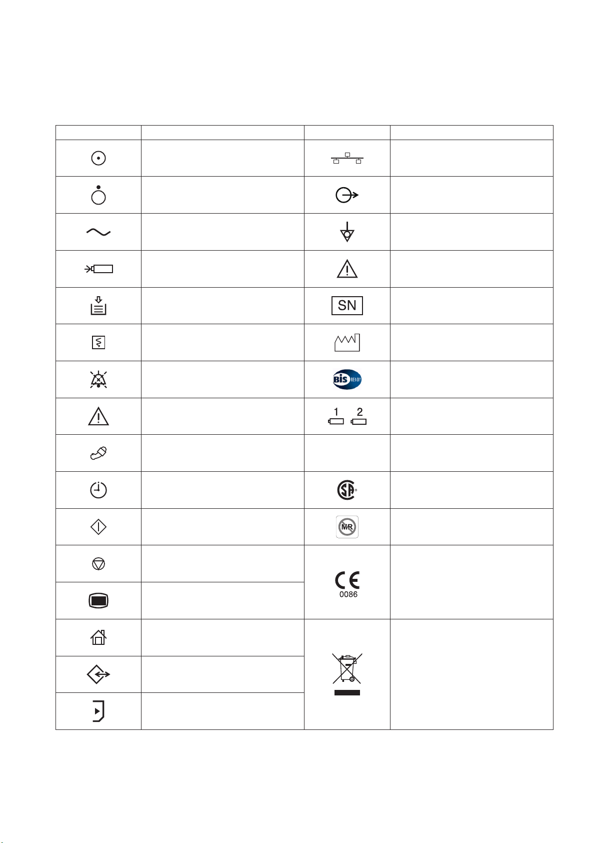
Explanations of the Symbols in this Manual and Instrument
The following symbols found in this manual/instrument bear the respective descriptions as given.
MU-631R/MU-651R/MU-671R Main Unit
Symbol Description Symbol Description
“On” only for a part of instrument Network socket
“Off” only for a part of instrument Output terminal
Alternating current Equipotential terminal
Battery charging Attention, consult operator’s manual
Out of paper Serial number
Record Date of manufacture
Alarm silence BIS processor/BISx
Attention, consult operator’s manual
NIBP
ZS
Battery slot 1/Battery slot 2 (MU-631R
only)
ZS socket
NIBP interval CSA mark*
NIBP start MR unsafe*
The CE mark** is a protected
NIBP stop
conformity mark of the European
Community. Products marked with this
symbol comply with the requirements
Menu
of the Medical Device Directive 93/42/
EEC.
Home
Products marked with this symbol**
comply with the European WEEE
directive 2002/96/EEC and require
Data input/output
separate waste collection. For Nihon
Kohden products marked with this
symbol, contact your Nihon Kohden
SD card slot
representative for disposal.
* The CSA mark and MR unsafe mark only apply to the MU-631RA/MU-651RA/MU-671RA.
** The CE mark and WEEE mark only apply to the MU-631RK/MU-651RK/MU-671RK.
User’s Guide Part I BSM-6000 vii
Page 20
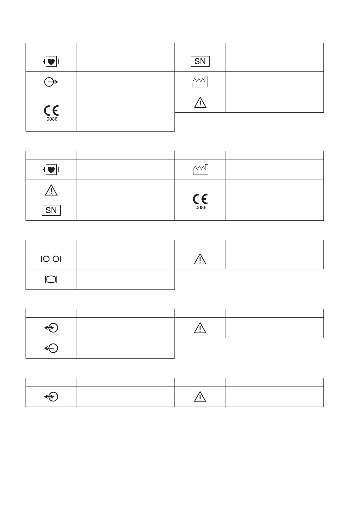
AY Series Input Unit
Symbol Description Symbol Description
Debrillation-prooftypeCFapplied
part
Output terminal Date of manufacture
The CE mark is a protected conformity
mark of the European Community.
Products marked with this symbol
comply with the requirements of the
Medical Device Directive 93/42/EEC.
AA-672P/AA-674P Smart Expansion Unit
Symbol Description Symbol Description
Debrillation-prooftypeCFapplied
part
Attention, consult operator’s manual
Serial number
Serial number
Attention, consult operator’s manual
Date of manufacture
The CE mark is a protected conformity
mark of the European Community.
Products marked with this symbol
comply with the requirements of the
Medical Device Directive 93/42/EEC.
QI-631P Interface
Symbol Description Symbol Description
Serial interface (RS-232C socket) Attention, consult operator’s manual
External display (RGB socket)
QI-632P Interface
Symbol Description Symbol Description
Input/output terminal (USB socket and
Multi-link socket)
Output terminal (Alarm socket)
QI-634P Interface
Symbol Description Symbol Description
Input/output terminal (USB socket and
Multi-link socket)
Attention, consult operator’s manual
Attention, consult operator’s manual
viii User’s Guide Part I BSM-6000
Page 21

QI-671P Interface
Symbol Description Symbol Description
Input/output terminal (Multi-link
socket)
Serial interface (RS-232C socket) Attention, consult operator’s manual
Output (Alarm socket)
QI-672P Interface
Symbol Description Symbol Description
Input/output terminal (USB socket and
Multi-link socket)
WS-671P Recorder Module
Symbol Description Symbol Description
Attention, consult operator’s manual
Serial number
External display (RGB socket)
Attention, consult operator’s manual
The CE mark is a protected conformity
mark of the European Community.
Products marked with this symbol
comply with the requirements of the
Medical Device Directive 93/42/EEC.
Date of manufacture
SB-671P Battery Pack
Symbol Description Symbol Description
Date of manufacture Recycle mark
Products marked with this symbol
comply with the European WEEE
directive 2002/96/EEC and require
separate waste collection. For Nihon
Kohden products marked with this
symbol, contact your Nihon Kohden
representative for disposal.
On screen
Symbol Description Symbol Description
Alarm silence Accessing to SD card
Environmental protection use period:
10 years
The CE mark is a protected conformity
mark of the European Community.
Products marked with this symbol
comply with the requirements of the
Medical Device Directive 93/42/EEC.
Alarm suspended Checking SD card
All alarms off or vital sign alarm limit
off
Non-paced Adjust setting/Scroll data
User’s Guide Part I BSM-6000 ix
SD card failure
Page 22

Symbol Description Symbol Description
QRS/pulse sync mark Zoom in/Zoom out
Respiration sync mark Left end/Right end
Battery status
@
Touch panel calibration
x User’s Guide Part I BSM-6000
Page 23

Related Documentation
The BSM-6301A/K, BSM-6501A/K and BSM-6701A/K bedside monitors come with the following manuals in addition to
the operator’s manual.
Administrator’s Guide
Describes how to install the bedside monitor. It also explains about the password protected settings on the SYSTEM
SETUP window and SYSTEM CONFIGURATION screen which only an administrator can change.
User’s Guide, Part I
Gives supplemental information on the operation of the bedside monitor.
User’s Guide, Part II
Describes the features and settings of the monitoring parameters.
Service Manual
Describesinformationonservicingthebedsidemonitor.Onlyqualiedservicepersonnelcanservicethebedsidemonitor.
Safety Standards
Thesafetystandardofthisbedsidemonitorisclassiedasfollows:
Type of protection against electrical shock: CLASS I EQUIPMENT (AC Powered)
Internally Powered EQUIPMENT (BATTERY Powered)
Degree of protection against electrical shock
Degree of protection against electrical shock
Debrillator-prooftypeCFappliedpart
AY-631P, AY-633P, AY-651P, AY-653P, AY-661P, AY-663P, AY-671P and AY-673P:
ECG, Respiration (impedance and thermistor method), IBP, Temperature, SpO2,
CO2, O2, NIBP, BIS
AY-660P: ECG, Respiration (impedance method), IBP, Temperature, SpO2, CO2, NIBP
AA-672P and AA-674P: Respiration (thermistor method), IBP, Temperature, SpO2, CO2, O2, BIS
CF applied part:
AY-631P, AY-633P, AY-651P, AY-653P, AY-661P, AY-663P, AY-671P, AY-673P, AA-672P and AA-674P: CO
Degree of protection against harmful ingress of water: IPX0 (non-protected)
Degree of safety of application in the presence of FLAMMABLE ANAESTHETIC MIXTURE WITH AIR, OR WITH
OXYGEN OR NITROUS OXIDE:
Equipment not suitable for use in the presence of FLAMMABLE ANAESTHETIC MIXTURE WITH AIR, OR
WITH OXYGEN OR NITROUS OXIDE
Mode of operation: CONTINUOUS OPERATION
Safety Information
This User’s Guide only contains safety information related to operation. Full information is in the BSM-6000A/K series
Bedside Monitor Operator’s Manual (code number: 0614-900685H).
User’s Guide Part I BSM-6000 xi
Page 24

Section 1 General
Introduction .......................................................................................................................................................... 1.3
General ......................................................................................................................................................1.3
Applications ..................................................................................................................................... 1.4
Features .......................................................................................................................................... 1.4
Measurement Parameters, and Applicable Units ............................................................................ 1.6
Composition .........................................................................................................................................................1.8
Network Composition ..........................................................................................................................................1.9
Panel Description ..............................................................................................................................................1.10
MU-631R Main Unit ................................................................................................................................. 1.10
Front Panel .................................................................................................................................... 1.10
Left Side Panel .............................................................................................................................. 1.11
Right Side Panel ...........................................................................................................................1.11
Rear Panel .................................................................................................................................... 1.12
MU-651R/MU-671R Main Unit ................................................................................................................1.13
Front Panel .................................................................................................................................... 1.13
Left Side Panel .............................................................................................................................. 1.14
Right Side Panel ...........................................................................................................................1.14
Rear Panel .................................................................................................................................... 1.15
AY-631P/633P/651P/653P/660P/661P/663P/671P/673P Input Unit ....................................................... 1.16
Front Panel .................................................................................................................................... 1.16
Using MULTI Sockets for CO Monitoring .......................................................................................1.16
Using the Output Signal from the ECG/BP OUT Socket ............................................................... 1.17
Left Side Panel .............................................................................................................................. 1.18
Right Side Panel ...........................................................................................................................1.18
Rear Panel .................................................................................................................................... 1.19
AA-672P/AA-674P Smart Expansion Unit ............................................................................................... 1.19
Front Panel .................................................................................................................................... 1.19
Using MULTI Sockets for CO Monitoring .......................................................................................1.20
Right Side Panel ...........................................................................................................................1.20
QF series Interface and IF series Communication Cable ........................................................................1.21
RY-910PA Remote Controller ..................................................................................................................1.22
Basic Operating Concepts ................................................................................................................................. 1.23
Screen Displays ......................................................................................................................................1.23
Using Touch Screen Keys ....................................................................................................................... 1.29
Keys on the Bedside Monitor ................................................................................................................... 1.30
Using the Remote Control ....................................................................................................................... 1.31
Using the Mouse .....................................................................................................................................1.31
Using the Data Acquisition Unit ............................................................................................................... 1.32
Using the MENU Window ........................................................................................................................ 1.33
Transport Function .............................................................................................................................................1.34
Overview .................................................................................................................................................1.34
Requirements .......................................................................................................................................... 1.34
Necessary Settings Before Use ..............................................................................................................1.34
1
User’s Guide Part I BSM-6000 1.1
Page 25

Transported Data and Settings ................................................................................................................1.35
Sending Data to a CNS-9701 Central Monitor ........................................................................................ 1.36
Patient Authentication ..............................................................................................................................1.37
Preparing for Removing the Input Unit .................................................................................................... 1.41
Enabling the Input Unit ............................................................................................................................ 1.42
When the Input Unit is Disabled .................................................................................................... 1.42
Enabling the Input Unit .................................................................................................................. 1.42
1.2 User’s Guide Part I BSM-6000
Page 26

1. GENERAL
Introduction
General
1
The Life Scope TR BSM-6301A/K, BSM-6501A/K and BSM-6701A/K bedside
monitors are for one patient. You can combine the monitor with other units and
options depending on the measurement parameters and use the monitor in a wide
range of sites such as the operating rooms and intensive care unit (ICU).
You can also connect this monitor to a network to communicate with a central
monitor and other bedside monitors.
The BSM-6301A/K bedside monitor has a 10.4 inch TFT color display, BSM-
6501A/K has a 12.1 inch TFT color display, and BSM-6701A/K has a 15 inch
TFT color display. All models can display 15 waveforms on the screen.
Forsimplicity,thesufxA/G/Kwillbeomittedinthismanual.
WARNING
Do not diagnose a patient based on only part of the monitoring data
on the bedside monitor or only on the data acquired by the bedside
monitor. Overall judgement must be performed by a physician who
understands the features, limitations and characteristics of the
bedside monitor by reading this user’s guide thoroughly and by
reading the biomedical signals acquired by other instruments.
WARNING
Do not use the same monitor for more than one patient at the same
time. Do not connect different sensors from different patients to the
same monitor.
NOTE
• Upgrade the main unit and each optional unit to the Nihon Kohden
recommended software version. Only use the specified configuration of
units. If more than one BSM-6000 series bedside monitor is used in the
same facility, make sure the bedside monitors have the same software
version. If BSM-6000 series monitors with different software versions
are used together, correct system operation cannot be guaranteed.
• Be sure to have the administrator change settings for system operation
to modify purposes of system use or relocate the system, or have any
changes checked by the administrator. Inappropriate changes may
result in unsuitable monitoring or a missed alarm.
User’s Guide Part I BSM-6000 1.3
Page 27

1.4 User’s Guide Part I BSM-6000
1. GENERAL
Applications
This system monitors biological information on a patient in an operating room,
recovery room, ICU, CCU, HCU, NICU or emergency room.
Features
• Components
You can connect an input unit, smart expansion unit, interface and other
options to the main unit.
• Use of MULTI sockets
TheMULTIsocketsallowyoutoexiblyconnectdifferentparameters.
• Touch screen display
The wide angle TFT color display can display measurement values and up to
15 waveforms. You can operate the monitor by touching the screen.
• Use of remote control (Section 2)
The remote control allows operation at a distance.
• Telemetry system (Administrator’s Guide)
When the optional ZS-900P* transmitter is connected to the bedside monitor,
waveform(s) and parameter data from the bedside monitor can be sent to a
cardiac telemetry system or to a central monitor via a multiple patient receiver.
(Available waveforms and parameter data depend on the receiving monitor.
CO, O2 and anesthetic gas data cannot be transmitted.)
* ZS-900P is not available for BSM-6000A series.
• Available network connection (Administrator’s Guide)
You can connect this system via a 10/1000BASE-T LAN cable to a network to
communicate with the central monitor and other devices.
• Available backup battery
When an SB-671P battery pack (option) is installed in the monitor, there is
a sudden power failure or during patient transfer, the monitor can be operated
continuously on battery power.
• Home screen (Administrator’s Guide)
You can change the home screen display according to the needs of your
facility.
• Trendgraphs and OCRG display on the home screen (Administrator’s
Guide)
The home screen displays trendgraphs of measured values and waveforms so
you can easily identify changes in the patient condition. When a neonate is
monitored, OCRG can also be displayed instead of trendgraphs.
• Review information (Section 6)
This system provides the capability to display review information as trends,
arrhythmia recall and full disclosure waveforms.
Page 28

1. GENERAL
• Thermal array recorder (Section 10)
You can install a WS-671P recorder module (option) to record up to three
waveforms and reports.
• Multi arrhythmia analysis mode (User’s Guide Part II, Section 1)
The multi arrhythmia analysis mode allows you to analyze arrhythmia more
accurately.
• ECG window (User’s Guide Part II, Section 1)
This system displays QRS waveforms of the normal waveform as the dominant
QRS, allowing you to check analysis accuracy.
• 12 lead analysis (Section 7)
When the 10-electrode ECG is monitored, you can display standard 12 lead
ECG. 12 lead interpretation is provided.
• Function keys (Administrator’s Guide)
You can register frequently used operations to function key.
• Different site setting (Administrator’s Guide)
You can set different settings for different sites (OR, ICU and NICU).
1
Standard components
• MU-631R, MU-651R, MU-671R main unit
• QI-631P, QI-632P, QI-634P, QI-671P, QI-672P interface
• AY-631P, AY-633P, AY-651P, AY-653P, AY-660P*, AY-661P*, AY-663P*,
AY-671P, AY-673P input unit
* AY-660P, AY-661P and AY-663P input units are not available for BSM-
6000A series.
• AA-672P, AA-674P smart expansion unit
• WS-671P recorder module
• SB-671P battery pack
NOTE
When AY-660P input unit is used, the AA-672P or AA-674P smart
expansion unit cannot be used.
When an AY-600P series input unit has a QM-600P memory unit installed, the
data of the bedside monitor can be saved and sent to another bedside monitor.
For details, refer to the “Transport Function” section.
User’s Guide Part I BSM-6000 1.5
Page 29

1.6 User’s Guide Part I BSM-6000
1. GENERAL
Measurement Parameters, and Applicable Units
Applicable Units
QI-632P
Measurement Parameters
AY series
Input Unit
QI-634P
QI-671P
QI-672P
Other Units
Interface
ECG OK – –
Respiration
Impedance method OK – –
Thermistor method OK
Mainstream OK
*1
*1
– –
– –
• AG-400R CO2 unit
*3
• AG-920R multigas unit
CO
SpO
2
2
Sidestream – OK
OK – –
• GF-110PA multigas unit
•GF-120PAmultigas/owunit
• GF-210R multigas unit
*3
•GF-220Rmultigas/owunit
*3
*3
NIBP OK – –
IBP OK
Temperature
BIS
TEMP socket OK – –
MULTI socket OK
MULTI socket – OK
*1
*1
– –
– –
• YJ-671P BISx connection cable
• QE-910P BIS processor/BISx
Multi-link socket – OK External instrument
Cardiac output OK
*1
OK –
• AG-920R multigas unit
• GF-110PA multigas unit
Anesthetic gas
*2
– OK
•GF-120PAmultigas/owunit
• GF-210R multigas unit
•GF-220Rmultigas/owunit
*3
*3
*3
• AG-920R multigas unit
• GF-110PA multigas unit
O
2
OK
*1
–
•GF-120PAmultigas/owunit
• GF-210R multigas unit
•GF-220Rmultigas/owunit
*3
*3
*3
Ventilation – OK External instrument
TOF – OK External instrument
CCO – OK External instrument
FLOW/Paw – OK
•GF-120PAmultigas/owunit
•GF-220Rmultigas/owunit
EEG – OK AE-918P neuro unit
tcPO2/tcPCO
2
– OK External instrument
*3
*3
*3
*1 These parameters cannot be measured by the MULTI sockets on the AY-660P input unit, but can be
measured by the MULTI sockets on the JA-694PA data acquisition unit.
*2 RR, CO2 (Sidestream), O2, N2O, AGENT, MAC and FLOW/Paw can be measured.
*3 These units are not available for BSM-6000A series.
Page 30

1. GENERAL
Differences Between the Input Unit Models
Input Unit Model AY-631P AY-633P AY-651P AY-653P AY-660P*
AY-661P*
1
AY-671P
1
AY-663P*
AY-673P
No. of MULTI sockets 1 3 1 3 1 1 3
Available parameters
using MULTI sockets
RESP (Thermistor), CO2, SpO2, IBP,
TEMP, BIS, CO, O
2
CO2, IBP
RESP (Thermistor),
CO2, SpO2, IBP, TEMP,
BIS, CO, O
2
No. of TEMP sockets 2 1 2
ECG measurement
using 10 electrodes
Yes No Yes
12 lead analysis Yes No Yes
SpO2 probe Masimo Nellcor Nihon Kohden
Dual SpO
2
NIBP PWTT
measurement
Yes*
2
No Yes
Yes*
3
Yes*
4
Yes*
5
Smart expansion unit
Analog ECG
Analog BP
Yes No Yes
HT output
*1 AY-660P, AY-661P and AY-663P input units are not available for BSM-6000A series.
*2 IF-925P communication cable is required.
*3 IF-919P communication cable is required.
*4 Dual SpO2 is available when the MULTI socket on the JA-694PA data acquisition unit is used.
*5 JL-500P1 or JL-500P2 SpO2 adapter is required.
1
1
User’s Guide Part I BSM-6000 1.7
Page 31

1.8 User’s Guide Part I BSM-6000
1. GENERAL
BSM-6000 series Bedside Monitor
MU-671R MU-651R MU-631R
Main Unit
AY-631P/651P/
661P*/671P
AY-633P/653P/
663P*/673P
AY-660P*
Input Unit
SB-671P
Battery Pack
RY-910P
Remote Controller
DI-590P
Holder
Wireless LAN Station
QI-320PA
Example is QF-904P
QF-901P: for Drager ventilator
QF-902P: for Aspects BIS monitor
QF-903P: for Vigilance monitor
QF-904P: for AG-920R multigas unit
QF-905P: for AG-400R CO2 unit*
QF-907P: for Puritan Bennett ventilator
QF-908P: for MAQUET ventilator
QF-909P: for Oragnon neuromuscular transmission monitor
QF-911P: for Pulsion PiCCO plus/PiCCO2*
QF-921P: for Oridion Microcap®**
IF-913P: for Radiometer MicroGas 7650 rapid transcutaneous monitor
IF-914P: for Radiometer TCM4 or TCM40 transcutaneous monitor
IF-917P: for Hamilton Medical Ventilator*
IF-919P: for Covidien-Nellcor OxiMaxTM N-600xTM pulse oximeter
IF-920P: for Dräger Medical Primus/Fabius® anesthesia workstation
IF-922P: for Hospira SO2/CCO monitor
IF-923P: for Puritan Bennett ventilator, 7200
IF-925P: for Masimo pulse oximeter
Interface/Communication Cable
* These units are not available for BSM-6000A series.
** This unit is only available for BSM-6000A series.
KC-600P Cart
KG-951P Wall Mount Kit
DH-600P Handle
Other
DH-220P
Mount Adapter
DH-223P
Unit Mount
Hyper Isolation Transformer
QW-100Y(HIT-100)
CO2 Unit
AG-400R
Transmitter
ZS-900P*
Multigas Unit/Multigas/Flow Unit
GF-110PA/GF-120PA*
GF-210R*/GF-220R*
Multigas Unit
AG-920R
WS-671P
AA-672P AA-674P
Smart Expansion Unit
Recorder Module
Interface
QI-671P
QI-672P
QI-631P
QI-632P QI-634P
For MU-631R
For MU-651R, MU-671R
JA-690PA JA-694PA
QI-600P Interface Unit
YS-096P2/096P3
Unit Connection Cable
YS-096P5 Multi-link Cable
DH-691P Base
DH-692P Holder
DH-693P Adapter
Data Acquisition Unit
Neuro Unit
AE-918P*
BIS Processor
QE-910P
Mouse Bar Code Reader
Composition
Page 32

1. GENERAL
Bedside monitor
Examples: BSS-9800
BSM-9100 series
BSM-5100 series
BSM-2300 series
Transmitter
Multiple patient
receiver
Network group
Example: ICU
Bedside monitor
Network group
Example: CCU
Central monitor Central monitor Central monitor
Bedside monitor Bedside monitor
* This system is provided with monitors, transmitters and multiple patient
receivers whose models are the same as those of the ICU group.
Bedside Monitor
BSM-6000 series
Central monitor
Central monitor
Another network system
Printer
Multiple patient
receiver
Transmitter Transmitter
Bedside monitor
Examples: ORG-9700
ORG-9100
Examples: CNS-9701
CNS-9601
Examples: CNS-9701
CNS-9601
Network Composition
In a central monitor network, on a central monitor, you can see data of any bed in
the network.
The data that can be displayed on the bedside monitor or central monitor depends
on the type of bedside or central monitor used.
The number of central monitors and bedside monitors that can be connected to a
central monitor network and the network communication method depends on the
type of monitor used. For details, refer to the Network and System Installation
Guide.
1
Install all network devices, including printer and
hubs, outside the patient environment (IEC
60601-1-1). If they are installed inside the patient
environment, the patient or operator may receive
electrical shock or injury. For installation, contact
your Nihon Kohden representative.
User’s Guide Part I BSM-6000 1.9
WARNING
Check the software version number of the monitor
before connecting it to the network. Different
software versions have different communication
methods. More than one communication method
in a network may cause communication failure.
For details, refer to the Network and System
Installation Guide.
WARNING
Page 33

1.10 User’s Guide Part I BSM-6000
1. GENERAL
Panel Description
MU-631R Main Unit
Front Panel
1 2 3
4
5
6
7
8
17
16
9
1 Touch screen
Displays monitoring data. Touching a key or data on the
screen changes the displayed screen and settings.
2 Alarm indicator
Red or yellow lamp blinks, or yellow or cyan lamps lights
according to the alarm settings. Green lamp blinks in
synchronization with the patient’s QRS or pulse.
3 Handle
For carrying the monitor.
4 Silence Alarms key
Silences the alarm sound.
5 NIBP Interval key
Selects NIBP measurement mode. Pressing this key changes
the mode.
6 NIBP Start/Stop key
Starts NIBP measurement in selected mode. Pressing the
key during measurement stops measurement.
7 Menu key
Displays the MENU window.
8 Home key
Closes all opened windows and displays the home screen.
10 11 12 13 14
15
9 Power switch
Press to turn the monitor power on. When turning the
monitor power off, press and hold for more than three
seconds.
10 Power lamp
Lights when the monitor power is turned on.
11 AC power lamp
Lights when the power cord is connected between the AC
SOURCE socket and AC outlet.
12 Battery lamp 1
Indicates a battery status of the battery in the battery slot 1.
13 Battery lamp 2
Indicates a battery status of the battery in the battery slot 2.
14 Remote control sensor
Receives an infrared signal from the remote control.
15 ERROR lamp (option)
Blinks when out of paper. Lights when the recorder door is
open.
16 RECORD/STOP key (option)
Press to start or stop recording.
17 Speaker
For alarms and sync sound.
Page 34

1. GENERAL
Left Side Panel
When the AY-673P input unit is installed
AY-673P
When the AY-673P input unit and AA674P smart expansion unit are installed
AA-674P
AY-673P
1
1
2
1 Input unit socket
Connects an AY series input unit.
2 Battery pack holder 1 (Battery slot 1)
For an SB-671P battery pack.
Right Side Panel
1
2
3
1 SD card slot
For an SD card or program card.
2 ZS socket
For the ZS-900P* transmitter.
* ZS-900P transmitter is not available for BSM-6000A
series.
When the WS-671P recorder module
is installed
4
5
3 Network socket
Connects to monitor network system via the network
separation unit.
4 Recorder module holder
For the WS-671P recorder module.
5 Battery pack holder 2 (Battery slot 2)
For an SB-671P battery pack.
User’s Guide Part I BSM-6000 1.11
Page 35

1. GENERAL
Rear Panel
Example shows the QI-631P and QI-632P interfaces installed.
When the optional interface is connected
5
QI-632P QI-631P
8
9
6
1
2
7
1 QI-632P/QI-634P interface socket
Connects the QI-632P or QI-634P interface.
2 QI-631P interface socket
Connects the QI-631P interface.
3 AC SOURCE power cord socket
For the AC power cord.
4 Equipotential grounding terminal
For an equipotential grounding lead.
5 USB socket (QI-632P/QI-634P)
Connects a mouse or bar code reader.
4
3
6 Multi-link socket (QI-632P/QI-634P)
Connects a QF series interface, IF series communication
cable or multi-link cable of an external unit.
7 Alarm socket (QI-632P)
Connects a YJ-672P nurse call cable.
8 RS-232C socket (QI-631P)
Connects a YJ-672P nurse call cable.
9 RGB socket (QI-631P)
Outputs the RGB video signal. Connects to the slave
display.
1.12 User’s Guide Part I BSM-6000
Page 36

1. GENERAL
MU-651R/MU-671R Main Unit
Front Panel
1 2 3
1
4
5
6
7
8
9
1 Touch screen
Displays monitoring data. Touching a key or data on the
screen changes the displayed screen and settings.
2 Alarm indicator
Red or yellow lamp blinks, or yellow or cyan lamps lights
according to the alarm settings. Green lamp blinks in
synchronization with the patient’s QRS or pulse.
3 Handle
For carrying the monitor.
4 Silence Alarms key
Silences the alarm sound.
5 NIBP Interval key
Selects NIBP measurement mode. Pressing this key changes
the mode.
6 NIBP Start/Stop key
Starts NIBP measurement in selected mode. Pressing the
key during measurement stops measurement.
7 Menu key
Displays the MENU window.
8 Home key
Closes all opened windows and displays the home screen.
10 11 12 13 14
17
16
15
9 Power switch
Press to turn the monitor power on. When turning the
monitor power off, press and hold for more than three
seconds.
10 Power lamp
Lights when the monitor power is turned on.
11 AC power lamp
Lights when the power cord is connected between the AC
SOURCE socket and AC outlet.
12 Battery lamp 1
Indicates a battery status of the battery in the battery slot 1.
13 Battery lamp 2
Indicates a battery status of the battery in the battery slot 2.
14 Remote control sensor
Receives an infrared signal from the remote control.
15 ERROR lamp (option)
Blinks when out of paper. Lights when the recorder door is
open.
16 RECORD/STOP key (option)
Press to start or stop recording.
17 Speaker
For alarms and sync sound.
User’s Guide Part I BSM-6000 1.13
Page 37

1.14 User’s Guide Part I BSM-6000
1. GENERAL
Left Side Panel
When the AY-673P input unit is installed
AY-673P
When the AY-673P input unit and AA674P smart expansion unit are installed
1
2
AA-674P
Right Side Panel
AY-673P
1 Input unit socket
Connects an AY series input unit.
2 Battery pack holder
For an SB-671P battery pack.
When the WS-671P recorder module
is installed
1
2
3
1 SD card slot
For an SD card or program card.
2 ZS socket
For the ZS-900P* transmitter.
* ZS-900P transmitter is not available for BSM-6000A
3 Network socket
Connects to monitor network system via the network
separation unit.
4 Recorder module holder
For the WS-671P recorder module.
4
series.
Page 38

1. GENERAL
Rear Panel
When the optional interface is connected
5
QI-672P QI-671P
7
8
9
10
1
1
2
6
1 QI-672P interface socket
Connects the QI-672P interface.
2 QI-671P interface socket
Connects the QI-671P interface.
3 AC SOURCE power cord socket
For the AC power cord.
4 Equipotential grounding terminal
For an equipotential grounding lead.
5 USB sockets
Connects to a mouse or bar code reader.
6 Multi-link sockets
Connects a QF series interface, IF series communication
cable or multi-link cable of an external unit.
7 Multi-link sockets
Connects a QF series interface, IF series communication
cable or multi-link cable of an external unit.
8 RS-232C socket
Not available.
4
3
9 Alarm socket
Connects a YJ-672P nurse call cable.
10 RGB socket
Outputs the RGB video signal. Connects to the dual display
or slave display.
User’s Guide Part I BSM-6000 1.15
Page 39

1.16 User’s Guide Part I BSM-6000
1. GENERAL
AY-631P/633P/651P/653P/660P/661P/663P/671P/673P Input Unit
Front Panel
One MULTI socket
Example is AY-671P input unit.
AY-660P: One TEMP socket, one MULTI socket, no ECG/BP OUT socket
AY-631P/AY-651P/AY-661P/AY-671P: One MULTI socket
AY-633P/AY-653P/AY-663P/AY-673P: Three MULTI sockets
2
1
5
6
Three MULTI sockets
Example is AY-673P input unit.
NOTE
• AY-660P, AY-661P and AY-663P input units are not available for BSM-
6000A series.
• With the MULTI socket on the AY-660P input unit, either IBP or CO2 can
be monitored.
1 MULTI socket
3
4
Connects to the connection cord of the parameter to be monitored (IBP,
temperature, CO, CO2, SpO2-2 (AY-661P, AY-663P, AY-671P or AY-673P
only), O2, respiration by thermistor method or BIS). The type of parameter is
automatically recognized.
2 TEMP socket
Connects to the temperature probe cable.
3 SpO2 socket
Connects to the SpO2 connection cord.
4 ECG/RESP socket
Connects to the ECG connection cord.
5 ECG/BP OUT socket
Outputs 100 mmHg/V IBP waveform and 1 mV/V ECG waveform by using the
YJ-910P or YJ-920P ECG/BP output cable. These analog signals can be used as
the synchronization signal for other equipment, such as IABP.
6 NIBP socket
Connects to the air hose.
2
WARNING
Connect only the specified instrument to the monitor and follow the
specified procedure. Failure to follow this warning may result in
electrical shock or injury to the patient and operator, and cause fire
1
3
4
5
6
or instrument malfunction.
Using MULTI Sockets for CO Monitoring
WARNING
When performing defibrillation during cardiac output monitoring, never
touch the CO connection cord. The discharged energy may cause
electrical shock or injury.
NOTE
CO monitoring using the MULTI socket does not comply with the
defibrillator proof type CF.
Page 40

1. GENERAL
Using the Output Signal from the ECG/BP OUT Socket
CAUTION
When using the output signal from the monitor as
the synchronization signal for other equipment
such as an IABP (intra-aortic balloon pump) or
defibrillator:
• Set the timing of the IABP by checking the
waveform on the IABP screen.
• Check the condition of the bedside monitor
at all times. The output signal may become
unstable.
• Check that the delay time of the output signal is
within the range of the connected equipment.
• When using an IBP waveform as a synchronization signal for other
equipment, connect the IBP line to the MULTI socket on the input unit.
The IBP waveform that is used for the synchronization signal depends
on the “IBP ANALOG OUT” setting in the SYSTEM SETUP window.
- When “IBP ANALOG OUT” is set to “FIXED POSITION”:
The IBP line connected to the top MULTI socket on the input unit is
used.
- When “IBP ANALOG OUT” is set to “HIGHEST PRIORITY LABEL”:
When more than one IBP waveform is acquired, the IBP waveform of
the highest priority label is used.
IBP label priority:
ART > ART2 > RAD > DORS > AO > FEM > UA > LVP > P1 > P2 >
P3 > P4 > P5 > P6 > P7
• The output signal from the ECG/BP OUT socket may become unstable
in the following conditions.
- Electrode is dry or detached.
- Electrode lead is damaged or disconnected from the electrode.
- Electrode lead is pulled.
- AC interference or EMG noise superimposed.
- Air bubbles or blood clog in the circuit for monitoring IBP.
- Cord or cable is disconnected or damaged.
• All instruments which are to be connected to the ECG/BP OUTPUT
socket must use a YJ-910P or YJ-920P ECG/BP output cable and
comply with the IEC 60601-1 safety standard for medical equipment.
• When using an IABP, set <CALCULATION METHOD> on the OTHER
page of the PRESS window to “PEAK” to improve measurement
accuracy.
1
CAUTION
Only a Nihon Kohden defibrillator can use the
output signal from the monitor as a synchronization
signal. Check that the delay time of the output
signal (heart rate trigger 20 ms maximum) is within
the range of the connected defibrillator.
NOTE
Output Signal Delay Time
Output Signal Delay Time
ECG maximum 20 ms
IBP maximum 40 ms
Heart rate trigger maximum 20 ms
User’s Guide Part I BSM-6000 1.17
Page 41

1.18 User’s Guide Part I BSM-6000
1. GENERAL
Left Side Panel
When the side panel is removed
1 2
1 Side panel
Remove to attach an AA-672P or AA-674P smart expansion unit.
2 Smart expansion unit socket
Connects an AA-672P or AA-674P smart expansion unit.
Right Side Panel
1
1 Tabs
Match the tabs on the input unit to the slots on the bedside monitor.
Page 42

1. GENERAL
Rear Panel
1 Lock release lever
Lift up the lever to remove the input unit from the bedside monitor.
2 Input unit socket
For connecting a bedside monitor.
1
1
2
AA-672P/AA-674P Smart Expansion Unit
AA-672P or AA-674P smart expansion unit cannot be used with AY-660P
input unit.
Front Panel
AA-672P
1
NOTE
AA-674P
1
1 MULTI socket
Connect to the connection cord of the parameter to be monitored (Respiration by thermistor method, CO2, SpO2-2 (only
when an AY-661P, AY-663P, AY-671P or AY-673P input unit is used), IBP, temperature, CO, O2 or BIS). The type of
parameter is automatically recognized.
User’s Guide Part I BSM-6000 1.19
Page 43

1.20 User’s Guide Part I BSM-6000
1. GENERAL
Right Side Panel
Using MULTI Sockets for CO Monitoring
WARNING
When performing defibrillation during cardiac output monitoring,
never touch the CO connection cord. The discharged energy may
cause electrical shock or injury.
NOTE
CO monitoring using the MULTI socket does not comply with the
defibrillator proof type CF.
1
1 Connector
Connects an AY-631P, AY-633P, AY-651P, AY-653P, AY-661P, AY-663P, AY-671P or AY-673P input unit.
Page 44

1. GENERAL
QF series Interface and IF series Communication Cable
1
1 Multi-link connector
Connect to the multi-link socket on the bedside monitor.
2 External device connector
Connect to an external device.
3 Ferrite core
2
1
3
User’s Guide Part I BSM-6000 1.21
Page 45

1.22 User’s Guide Part I BSM-6000
1. GENERAL
MENU/HOME
POWER
DISPLAY
SELECT
CHANNEL
SILENCE
ALARMS
RY-910PA Remote Controller
6
1
2
7
8
11
12
9
10
3
5
4
Display number
1 Power button
When the power cord is connected between the bedside
monitor and AC outlet, turns the monitor power on or off.
2 MENU/HOME key
Opens the MENU window. Closes the window and displays
the home screen when a window is opened.
3 DISPLAY SELECT key
Not available.
4 Strap hole
Use a strap to prevent dropping the remote control.
5 Display
Displays the channel number and the display number.
6 Selection knob
Move this knob up/down/left/right to move the cursor or
mouse pointer on the screen.
7 LED
Lights when the pointer on the screen is moved by the
selection knob. Blinks when a key on the remote control is
pressed.
Channel number
8 SILENCE ALARMS key
Silences the alarm sound.
9 Customized keys
Windows and functions can be assigned to each key for
shortcut key operations.
10 CHANNEL keys
Select the monitor when a channel is assigned to the
monitor.
11 Transmitter
Signal is transmitted from here. Point the transmitter to
the remote control sensor on the bedside monitor when
operating the monitor with the remote control.
12 ENTER key
Registers the setting selected on the screen.
Page 46

1. GENERAL
Basic Operating Concepts
Screen Displays
Following are the screens and windows available on the Life Scope TR
bedside monitor. For details about the individual screens and windows, see the
appropriate section.
The shadow of the previous screen may remain for a few minutes after changing
the screen.
Normally, the home screen is displayed. All screens, except for the LARGE
NUMERICS screen, 12 LEAD ANALYSIS window and SYSTEM
CONFIGURATION screen, return to the home screen when there is no key
operation for about 3 minutes.
Home screen
1
• The home screen can be displayed anytime
by pressing the [Home] key on the bedside
monitor.
• Displays waveforms and data of the
monitoring parameters.
• Touching the patient name displays
the ADMIT page for changing patient
information.
• Touching the parameter data displays the
parameter setting window.
MENU window
The MENU window can be displayed anytime
by pressing the [Menu] key on the bedside
monitor. From the MENU window, you can
display any window except the home screen.
User’s Guide Part I BSM-6000 1.23
Page 47

1.24 User’s Guide Part I BSM-6000
1. GENERAL
Other windows for monitoring
ENLARGED window for displaying numeric data
12 LEAD ANALYSIS window for displaying simultaneous 12 lead ECG. 12 lead ECG interpretation can be performed.
Only available when the site mode is OR or ICU.
SLEEP window for turning sleep mode on.
Page 48

1. GENERAL
Review windows
• TREND GRAPH page for displaying 24 hour trendgraphs of up to 6 selected parameters.
• TREND TABLE page for displaying table of parameter data.
• NIBP page for displaying vital signs data with NIBP measurement.
• HEMO page for displaying hemodynamics data when CO is measured.
• LUNG TREND page for displaying lung function measurement data.
ARRHYTH RECALL window for displaying arrhythmia recall data.
1
ALARM HISTORY window for displaying vital sign data at alarm occurrence.
FULL DISC window for displaying full disclosure waveforms. Up to 5 parameters can be saved.
User’s Guide Part I BSM-6000 1.25
Page 49

1.26 User’s Guide Part I BSM-6000
1. GENERAL
ST window for displaying ST level recall waveforms. ST measurement condition can be changed.
12 LEAD window for displaying 12 lead ECG interpretation and analysis result data.
Only available when the site mode is OR or ICU.
OCRG window for displaying OCRG trendgraph.
Only available when the site mode is NICU.
ADMIT window
ADMIT window for admitting a patient. Data can be deleted on this window.
Page 50

1. GENERAL
Alarm setting window
ALARM LIMITS window for setting vital signs alarm and ARRHYTH ALARMS window for setting arrhythmia alarms.
Parameter setting windows
For changing parameter monitoring settings. Example is ECG window. FLOW/Paw and EEG are not available for BSM-
6000A series.
1
Interbed window
For displaying interbed beds when the monitor is connected to a network.
Drug calculation window
For registering drug and units, calculating drug and displaying the table of the selected drug titration.
User’s Guide Part I BSM-6000 1.27
Page 51

1.28 User’s Guide Part I BSM-6000
1. GENERAL
Setup and other windows
• DATE window for changing date and time
• VOLUME window for changing alarm and sync sound volume
• DISPLAY window for setting number of ECG waveforms on the home screen, PRESS waveform display type, waveform
sweep speed, and respiration/CO2 waveform sweep speed
• RECORD window for setting recording parameters
• SYSTEM window for checking assigned functions to the remote control keys
TOUCH KEYS OFF window for turning touch screen function off
Page 52

1. GENERAL
Using Touch Screen Keys
1
Any window can be opened and settings can be changed by touching the keys
anditemsonthescreenwithyournger.Touchingthekeyonthescreendisplays
the window. You can use the scroll bar on the screen to scroll data on the
window.
There is a pip sound when a key or screen is touched, or the scroll bar on the
screen is used.
Tabs for chaning displaying window
Selected items are highlighted
Setting bar
Touch or drag the sliders to the
desired level on the setting bar.
Upper limit slider
Lower limit slider
Cursor
Scroll bar
Scroll keys
User’s Guide Part I BSM-6000 1.29
Page 53

1.30 User’s Guide Part I BSM-6000
1. GENERAL
The time width of the trendgraph on the home screen can be adjusted by touching the right edge of the trendgraph and
dragging it left or right.
Keys on the Bedside Monitor
Turns the monitor power on or off
Silences alarm sound
Selects NIBP measurement mode
Starts and stops NIBP measurement
Displays the MENU window
Displays the home screen
Starts and stops recording (option)
Page 54

1. GENERAL
1
Using the Remote Control
1
Use the RY-910PA remote controller to operate the monitor from a distance.
A pointer appears on the screen when the monitor is operated by the remote
control. The remote control channel can be assigned to the monitor to prevent
operating a different monitor. Point the remote control at the remote control
sensor on the bedside monitor.
Press the keys on the remote control to open/close a window. Move the selection
knob up/down/left/right to scroll the data or select a setting and press the
[ENTER] key to register the setting.
There is a pip sound when a key on the remote control is pressed or the selection
knob is moved to scroll the data.
Using the Mouse
NOTE
• Watch the monitor screen and check the operation when using the
remote control to avoid wrong operation.
• Make sure that the remote control is handled appropriately.
When connecting a QI-632P, QI-634P or QI-672P interface, use the mouse to
move the pointer on the screen and click the left button to select and register the
setting.
There is a pip sound when the mouse is clicked.
User’s Guide Part I BSM-6000 1.31
Page 55

1.32 User’s Guide Part I BSM-6000
1. GENERAL
Using the Data Acquisition Unit
With the JA-690PA or JA-694PA data acquisition unit, you can use an input unit
that is separate from the bedside monitor. With the keys on the data acquisition
unit, you can operate the bedside monitor remotely. For details, refer to the JA-
690PA or JA-694PA data acquisition unit manual.
Page 56

1. GENERAL
Using the MENU Window
Section 6
Section 5
Section 3
1
The MENU window can be displayed anytime by pressing the [Menu] key on the
bedside monitor. From the MENU window, you can display any window except
the home screen. The MENU window layout differs according to the selected
site. Refer to “SITE Window” in Administrator’s Guide, Section 2.
Fordetailsoneachwindow,refertothesectionspeciedbelow.
When the site mode is OR or ICU
User’s Guide, Part II
Section 7
FLOW/Paw and EEG are
not available for BSM6000A series.
Section 10
Section 6
Section 5
Section 3
Section 8
Section 5
Section 4Administrator’s Guide
Section 9 Section 4Section 11
For the alarm off key on the MENU window, refer to “Silencing and Suspending
Alarms” in Section 5.
When the site mode is NICU
User’s Guide, Part II
FLOW/Paw and EEG are
not available for BSM6000A series.
Section 8
Section 5
Section 10
Section 4Administrator’s Guide
Section 9 Section 4Section 11
User’s Guide Part I BSM-6000 1.33
Page 57

1.34 User’s Guide Part I BSM-6000
1. GENERAL
Transport Function
Overview
Requirements
The monitor has a transport function. Patient information and review data can
be sent to another bed by disconnecting the input unit from the monitor or JA-
690PA or JA-694PA data acquisition unit and connecting it into another monitor
or data acquisition unit.
If the original monitor and destination monitors are in the same central monitor
network, you can observe the transported patient continuously from the central
monitor.
NOTE
• Transport function not using the network is available with BSM-6000
series bedside monitor software version 02-01 or later.
• Transport function using the network is available with BSM-6000 series
bedside monitor software version 02-02 or later.
• If the BSM-6000 series bedside monitors have different software
version, transport function cannot be used.
• Transport function using BSM-9101 bedside monitor is available with
BSM-6000 series bedside monitor software version 02-03 or later.
• A QM-600P memory unit must be installed in the input unit to use the
transport function.
Necessary Settings Before Use
CAUTION
If the patient data in the input unit has different measuring units from
the data in the main unit, an INPUT UNIT ERROR dialog box to
delete the data in the input unit appears. If you do not want to delete
the data in the input unit, touch the CANCEL key and remove the
input unit from the main unit.
CAUTION
When installing the monitor, change the time zone setting to the
same setting as the other bedside monitors and central monitors. If
the time zone setting is not the same, the data which was in the input
unit before transport is deleted when using the transport function
with the input unit.
Page 58

1. GENERAL
NOTE
• When <DATA TRANSPORT USING INPUT UNIT> on the TRANSPORT
window of the SYSTEM CONFIGURATION screen is set to ENABLE,
AUTO ADMIT is fixed to OFF. Refer to Section 2 of the Administrator’s
Guide.
• The unit settings must be the same on the input unit and main unit to
use the transport function. Refer to “UNITS Window” in Administrator’s
Guide, Section 2.
When <DATA TRANSPORT USING INPUT UNIT> on the TRANSPORT
window of the SYSTEM CONFIGURATION screen is set to ENABLE, the
patient data are saved in the optional QM-600P memory unit in the input unit.
Select ON or OFF on <USE SETTINGS IN INPUT UNIT> on the TRANSPORT
window of the SYSTEM CONFIGURATION screen to select whether to use
the settings on the original monitor at the destination monitor. Select ON or
OFF according to the operating environment. Refer to “TRANSPORT Window”
in Administrator’s Guide, Section 2 for the settings which can be used on the
destination monitor.
1
Transported Data and Settings
The following settings and data are saved in the QM-600P memory unit in the
input unit. Review data of past 24 hours can be sent.
The settings sent from the original monitor to the destination monitor depend
on <USE SETTINGS IN INPUT UNIT> on the TRANSPORT window of the
SYSTEM CONFIGURATION screen. Refer to “TRANSPORT Window” in
Administrator’s Guide, Section 2.
Settings
• Patient information (patient ID, name, date of birth, height, weight and gender)
• Pacing detection On or Off
• QRS detection type
• Arrhythmia analysis On or Off
• Vital sign upper/lower alarm limits settings
• Arrhythmia alarms settings
• Parameters to be saved for full disclosure and ECG lead settings of TRACE 1
and TRACE 2
Review data
NOTE
• The oldest file is deleted when the maximum number of files is saved.
• PCCO, ScvO2, SVV, EDV, EDVI, ESV, ESVI, EF, PPV and SPV data
on the GRAPH 1 to GRAPH 3 pages and TABLE 1 to TABLE 3 pages
of the TREND window cannot be saved in the input unit and cannot be
sent.
• EEG (monitored with the AE-918P neuro unit), SEF, MDF, PPF and TP
data cannot be saved in the input unit and cannot be sent.
User’s Guide Part I BSM-6000 1.35
Page 59

1.36 User’s Guide Part I BSM-6000
1. GENERAL
• When you enable the transport function, set the <SELECT THE WAVE
TO SAVE AND DISPLAY> setting on the FULL DISC window on both
the original monitor and the destination monitor to the same setting.
• Review data on the TREND windows
• Review data on the RECALL window
• Review data on the ALARM HISTORY window
• Full disclosure waveform (First trace of ECG and the four other waveforms
selected on the FULL DISC window)
• Review data on the ST window
• Review data on the 12 LEAD window
Sending Data to a CNS-9701 Central Monitor
Review data of the past 24 hours can be sent to a CNS-9701 central monitor.
WARNING
When using transport function, patient data may
be mixed together or lost in the following cases:
• Transport function and wireless LAN are used
at the same time.
• The network cable is connected or
disconnected from the bedside monitor or the
input unit is removed while the bedside monitor
power is off.
CAUTION
Do not remove the input unit while the data is
being sent to the central monitor. The data may
be lost.
The transport function is available with CNS-9701 central monitor
software version 01-77 or later.
WARNING
When you send data from the bedside monitor to
the central monitor, use a 10BASE-T or
100BASE-TX switching hub. If you use another
type of hub, the network may lose connection and
the patient cannot be monitored on the central
monitor.
NOTE
Review data
NOTE
• The oldest file is deleted when the maximum number of files are saved.
• When you enable the transport function, set the saved waveform setting
of the original monitor, destination monitor and the central monitor to
the same setting.
• PCCO, ScvO2, SVV, EDV, EDVI, ESV, ESVI, EF, PPV and SPV data on
the GRAPH 1 to GRAPH 3 pages and TABLE 1 to TABLE 3 pages of
the TREND window cannot be sent to another bed with the input unit.
• EEG (monitored with the AE-918P neuro unit), SEF, MDF, PPF and TP
data cannot be saved in the input unit and cannot be sent.
Page 60

1. GENERAL
Patient Authentication
• Data on the NIBP TREND page
• Data on the TABLE 1 to TABLE 3 pages
• Data on the GRAPH 1 to GRAPH 3 pages
• Data on the HEMO page
• Data on the RECALL window
• Full disclosure waveform (First trace of ECG and the four other waveforms
selected on the FULL DISC window)
• Review data on the ST window
• Data on the 12 LEAD window
If the input unit is removed from a monitor and connected to a monitor in a
central monitor network, the “SENDING DATA” message appears while the data
is being sent.
The SELECT PATIENT DATA window appears when the input unit is inserted
into the monitor or the monitor is turned on when the transport function is
enabled.
1
Authenticate the patient on the SELECT PATIENT DATA window and select the
monitoring patient.
• Use the patient information in the input unit (the data saved in the QM-600P
memory unit installed in the input unit)
• Use the patient information in the main unit (the data saved in the main unit)
• Start monitoring as a new patient
WARNING
When the input unit is connected to the monitor,
make sure to authenticate the patient on the
SELECT PATIENT DATA window. Otherwise,
monitoring cannot be started.
WARNING
Check the alarm settings after patient
authentication. The alarm settings depend on the
<USE SETTINGS IN INPUT UNIT> ON/OFF
setting on the TRANSPORT window of the
SYSTEM CONFIGURATION screen of the
destination monitor.
WARNING
Check the patient information and data range on
the SELECT PATIENT DATA window. Otherwise,
the patient may be incorrectly identified.
User’s Guide Part I BSM-6000 1.37
Page 61

1.38 User’s Guide Part I BSM-6000
1. GENERAL
1. Insert the input unit into the monitor and turn the power on. The SELECT
PATIENT DATA (INPUT UNIT) window appears.
CAUTION
If the patient data in the input unit has different measuring units from
the data in the main unit, an INPUT UNIT ERROR dialog box to
delete the data in the input unit appears. If you do not want to delete
the data in the input unit, touch the CANCEL key and remove the
input unit from the main unit.
NOTE
• The unit settings must be the same on the input unit and main unit to
use the transport function. Refer to “UNITS Window” in Administrator’s
Guide, Section 2.
• If the patient data in the input unit is damaged, an INPUT UNIT ERROR
dialog box appears. If the data in the input unit is not required, touch the
OK key to display the SELECT PATIENT DATA (MAIN UNIT) window
and select whether to use the data in the main unit.
Page 62

1. GENERAL
• If the input unit and main unit have different software versions, an
INPUT UNIT ERROR dialog box to delete the data in the input unit
appears. If you do not want to delete the data in the input unit, touch the
CANCEL key and remove the input unit from the main unit.
1
If an input unit without a QM-600P memory unit is inserted into the monitor, the
SELECT PATIENT DATA (MAIN UNIT) window appears. Do step 3 and select
whether to use the data in the main unit.
2. ConrmthepatientinformationanddatarangeontheSELECTPATIENT
DATA (INPUT UNIT) window and select whether to use the data in the
input unit.
• To use the data in the input unit or only use the data in the input unit and edit
the patient information
Touch the YES key and start monitoring.
• To use the data in the main unit or start monitoring as a new patient
Touch the NO key to display the SELECT PATIENT DATA (MAIN UNIT)
window.
NOTE
If the patient information in the input unit and main unit are the same, a
SELECT PATIENT DATA (INPUT UNIT) window appears. If you need to
start monitoring as a new patient, touch the OK key and delete the data
on the DELETE DATA page of the ADMIT window.
User’s Guide Part I BSM-6000 1.39
Page 63

1.40 User’s Guide Part I BSM-6000
1. GENERAL
Patient information in the input unit
Data range of the review data in
the input unit
3. Check the patient information and data range on the SELECT PATIENT
DATA (MAIN UNIT) window and select whether to use the data in the main
unit.
• To use the data in the main unit
Touch the YES key and start monitoring.
• To start monitoring as a new patient
Touch the NO key and display the PATIENT INFO page of the ADMIT
window to start monitoring as a new patient.
Patient information in the main unit
Data range of the review data in
the main unit
YES: Use the data in the main unit and start monitoring.
NO: Display the PATIENT INFO page and start
monitoring as a new patient.
BACK: Returns to the SELECT PATIENT DATA (INPUT
UNIT) window.
The BACK key is displayed only when there is data in the input unit.
Page 64

1. GENERAL
Preparing for Removing the Input Unit
When the transport function is enabled, perform the following procedure before
removing the input unit from the monitor.
WARNING
The monitor cannot start monitoring when the
input unit is not ready. When the preparation for
removing the input unit is complete, immediately
insert the input unit into the destination monitor.
If you removed the input unit but you will not transfer the patient, reinsert
the input unit into the original monitor and enable the input unit.
1. Display the REMOVE page.
Pressthe[Menu]key→ADMITkey→TRANSPORTDATAtab→
REMOVE tab.
1
CAUTION
When removing the input unit from the monitor
when the transport function is enabled, perform
the removal procedure of the input unit on the
REMOVE page of the TRANSPORT DATA
window before removing the input unit.
Otherwise, the data in the input unit may be lost.
NOTE
MessageMessage
NOTE
• When the patient is discharged and there is no need to send the patient
data to the central monitor, removing the input unit from the bedside
monitor is not necessary.
• If the QM-600P memory unit is not installed in the input unit or the
memory unit is damaged, the following message appears when the
REMOVE page is displayed: “This input unit has no memory unit or the
memory unit is damaged. Data cannot be transferred to another bed
with this input unit.”.
2. Touch the YES key to remove the input unit.
User’s Guide Part I BSM-6000 1.41
Page 65

1. GENERAL
Enabling the Input Unit
When the NO key is touched, it returns to the home screen.
3. The “PLEASE WAIT” message appears while the monitor is preparing for
the input unit removal. When preparation is complete, the “Remove the input
unit.” message appears.
4. Remove the input unit from the monitor.
When the Input Unit is Disabled
When the transport function is enabled and prepared for removing the input
unit on the monitor or when you remove the input unit without performing
the removal procedure, the input unit is disabled and the “CONNECT INPUT
UNIT” message appears.
When the input unit is disabled, the measurement values and waveforms are
not displayed on the home screen and the data cannot be saved in the monitor.
Authenticating the patient and changing the patient information are also not
available.
The drug calculation results, interbed data and review data before disabling the
input unit are displayed.
WARNING
The monitor cannot start monitoring when the input unit is not ready.
When the preparation for removing the input unit is complete,
immediately insert the input unit into the destination monitor.
Enabling the Input Unit
To enable the input unit, insert the input unit into the monitor and authenticate
the patient on the SELECT PATIENT DATA window. Refer to the “Patient
Authentication” earlier in this section.
1.42 User’s Guide Part I BSM-6000
Page 66

Section 2 Preparation
Preparation Flowchart .........................................................................................................................................2.2
Installation Conditions .........................................................................................................................................2.3
Inserting and Removing the Battery Pack ........................................................................................................... 2.5
Battery Handling and Operation ................................................................................................................ 2.5
Safety Information ........................................................................................................................... 2.5
Battery Pack Handling Procedures ................................................................................................. 2.6
When Not Using the Monitor or Battery Pack .................................................................................2.6
Inserting and Removing the Battery Packs ............................................................................................... 2.6
Inserting the Battery Pack ......................................................................................................................... 2.7
Removing the Battery Pack ....................................................................................................................... 2.8
Inserting and Removing the Input Unit ............................................................................................................... 2.9
Inserting the Input Unit .............................................................................................................................. 2.9
Removing the Input Unit ............................................................................................................................ 2.9
When the Transport Function is Enabled ......................................................................................2.10
Preparing the Optional Recorder ....................................................................................................................... 2.11
Installing the Recorder Module ................................................................................................................2.11
Loading Recording Paper ........................................................................................................................2.11
Preparing the Remote Control ........................................................................................................................... 2.13
Installing the Batteries ............................................................................................................................. 2.13
Setting the Remote Control Channel .......................................................................................................2.14
Attaching the Remote Control Channel Label to the Bedside Monitor .................................................... 2.14
Assigning Functions to the Customized Keys .........................................................................................2.14
Power .................................................................................................................................................................2.15
Connecting the Power Cord and Grounding the Monitor ......................................................................... 2.15
Connecting the Power Cord .......................................................................................................... 2.15
Grounding the Monitor ..................................................................................................................2.16
Turning the Power On ..............................................................................................................................2.16
Check Before Turning On the Power ............................................................................................. 2.16
Turning the Power On .................................................................................................................... 2.17
AUTO ADMIT Setting .................................................................................................................... 2.18
Check After Turning On the Power and During Monitoring............................................................ 2.18
Power and Battery Status Indications...................................................................................................... 2.19
When the “BATTERY WEAK” Message Appears .......................................................................... 2.20
Charging the Battery Pack ............................................................................................................ 2.20
Monitor Status on Power Interruption ...................................................................................................... 2.21
Turning the Power Off ..............................................................................................................................2.22
Check After/Before Turning the Power Off ..................................................................................... 2.22
2
User’s Guide Part I BSM-6000 2.1
Page 67

2.2 User’s Guide Part I BSM-6000
2. PREPARATION
Preparation Flowchart
You may not need to do all these.
1. Install the monitor. Refer to Administrator’s Guide.
2. Prepare battery pack, remote control and recorder. Refer to Section 2 in this
manual.
3. Check or change any initial settings on the SYSTEM CONFIGURATION
screen. Changing these settings during monitoring interrupts monitoring.
Refer to Administrator’s Guide, Section 2.
4. Check or change any initial settings on the SYSTEM SETUP window. These
settings are the password protected settings which only an administrator can
change. Refer to Administrator’s Guide, Section 3.
5. Check or change the necessary settings before monitoring in Section 3 in this
manual.
• Date and time
• Sound volume
• Screen brightness
• Waveform display settings
6. Enter the information of the new patient. Refer to “Entering Patient
Information” in Section 3 in this manual.
7. Check or change all alarm items for the patient. Refer to Section 5 in this
manual. When <AUTO ADMIT> in the SYSTEM CONFIGURATION
screen is set to ON, the alarm settings return to the default settings 30
minutes after the monitor is turned off. When <AUTO ADMIT> is set to
OFF, you can select whether to save the settings or initialize the master
settings.
8. Check or change settings for the review windows, such as trendgraphs,
tablesandarrhythmiarecallles.RefertoSection6inthismanual.
9. Check or change recording settings. Refer to Section 10 in this manual.
10. Prepare the equipment (electrodes, transducers, probes, etc.) for monitoring
individual parameters and check or change the settings for each parameter.
Refer to User’s Guide, Part II.
Page 68

Installation Conditions
Putthemonitoronastableandatstand,onanoptionalKC-600PcartorKG-
951P wall mount kit in a suitable location where the screen is easy to see and
doesnotreectlight.Followthecautionsbelow.
Themonitormustbeinstalledbyqualiedpersonnel.Detailsarein
Administrator’s Guide.
2. PREPARATION
2
WARNING
Never use the monitor in the presence of any
flammable anesthetic gas or high concentration
oxygen atmosphere. Failure to follow this warning
may cause explosion or fire.
CAUTION
Avoid collision when moving the monitor on a
cart. Strong impact may damage the monitor.
CAUTION
The display screen is made of glass. Strong
impact may damage it.
WARNING
Connect only the specified instrument to the
monitor and follow the specified procedure.
Failure to follow this warning may result
in electrical shock or injury to the patient
and operator, and cause fire or instrument
malfunction.
CAUTION
Avoid a location where the monitor is sprinkled
with liquids. Avoid direct sprinkling, spray or moist
air from a nebulizer or a humidifier.
CAUTION
Avoid locations where the monitor may receive
strong electromagnetic interference such as radio
or TV stations, cellular phones or mobile two-way
radios.
CAUTION
If fluids are accidentally spilled on the monitor,
take the monitor out of service and check for
damage.
Avoid exposing the monitor to direct sunlight.
CAUTION
Do not use the monitor in an ambulance. The
monitor may not function properly in a moving
vehicle.
Do not place blankets or cloth over the monitor. It
may affect monitoring.
CAUTION
Do not place the monitor in a dusty area.
User’s Guide Part I BSM-6000 2.3
Do not place the monitor in an MRI examination
room. The monitor may not function properly,
or noise from the monitor may interfere with the
MRI.
CAUTION
CAUTION
CAUTION
Page 69

2.4 User’s Guide Part I BSM-6000
2. PREPARATION
10 cm
5 cm Rear Panel
5 cm
Side Panel
CAUTION
Connect the power cord to an AC outlet which
can supply enough AC current to the monitor. The
monitor cannot function properly with low current.
CAUTION
Do not use an electrical blanket. It may affect
monitoring.
CAUTION
Make sure that there is more than 5 cm of space
between the monitor and the wall for adequate
ventilation. When the monitor is surrounded,
make sure that there is about 10 cm of space
above the monitor for ventilation so that the
operating temperature does not exceed 40°C
(104°F).
CAUTION
When there is any problem on the monitor, turn
off the power immediately and disconnect the
power cord from the AC outlet. Take the monitor
out of service and check for damage.
CAUTION
Avoid placing the monitor near a heater or
humidifier.
Page 70

Inserting and Removing the Battery Pack
Battery Handling and Operation
Safety Information
2. PREPARATION
2
WARNING
• Never short-circuit the + and − terminals on the
battery pack. It may cause overheating and fire.
• Keep the battery pack away from fire. It may
explode.
• Do not damage, disassemble, drop or give
impact to the battery pack.
• Never use the battery pack on unspecified
instruments.
• Never charge the battery pack on unspecified
instruments.
• Never install the battery pack with the wrong
polarity.
• Keep the battery pack away from patients.
CAUTION
Do not expose the battery pack to direct sunlight
or leave in a high temperature place. The
lifetime of the battery pack may be shortened,
the performance of the battery pack may be
degraded and the battery may leak.
CAUTION
Do not leave the battery pack near the patient or
in reach of children.
CAUTION
Do not tilt the monitor when removing the battery
pack from the monitor. If the lock release lever is
lifted while the monitor is tilted, the battery pack
falls out of the monitor and may injure the patient
or operator.
CAUTION
Do not use a battery pack which is past the
expiration date written on the label.
WARNING
If the battery pack is damaged and the substance
inside the battery contacts the eyes or skin, wash
immediately and thoroughly with water and see a
physician. Never rub your eyes, because you may
lose your eyesight.
WARNING
• Do not immerse the battery pack in water. The
battery pack may heat up and rust and the
substance inside the battery pack may leak.
• Do not leave the battery pack unused for more
than about two years. The battery pack may
leak.
CAUTION
Do not use a battery pack with a damaged cover.
The operator may receive electrical shock.
CAUTION
Do not subject the battery pack to a strong
mechanical shock.
CAUTION
Use the battery pack between 10°C (50°F) and
40°C (104°F). Temperatures out of this range
affect the working of the battery.
CAUTION
Before disposing of the battery pack, check with
your local solid waste officials for details in your
area for recycling options or proper disposal. The
battery pack is recyclable. At the end of its useful
life, under various state and local laws, it may
be illegal to dispose of this battery pack into the
municipal waste stream.
NOTE
Be careful when handling the fully charged battery pack. The battery pack
heats up to about 60°C (140°F).
User’s Guide Part I BSM-6000 2.5
Page 71

2.6 User’s Guide Part I BSM-6000
2. PREPARATION
Battery slot 1
Battery slot 2
Battery slot 1
Battery slot 2
BSM-6301 BSM-6501/BSM-6701
Battery Pack Handling Procedures
• Always place a battery pack in the monitor. This charges it so that you will
always have a fully charged battery pack ready.
• Fullyrechargethebatterypackbeforeusingitforthersttimeorafterstoring
it for over a month. When the battery is not used, it self-discharges.
• Replace the battery pack with a new one every year. This is because the battery
is a chemical product which gradually deteriorates whether or not it is used.
• Store the battery packs under the following conditions.
Temperature: –20 to +60°C (–4 to +140°F) (within 30 days)
–20 to +45°C (–4 to +113°F) (within 90 days)
–20 to +35°C (–4 to +95°F) (more than 90 days)
Humidity: 20 to 85% RH (noncondensing)
When Not Using the Monitor or Battery Pack
• When the monitor is not used for a long time, remove the battery pack. When
a charged or discharged battery pack is left inside the monitor with the power
cord unplugged, the battery self-discharges and deteriorates.
• When a battery pack is not used, fully charge it before storage. When a battery
pack is not used for over one month, fully charge it once every six months.
Inserting and Removing the Battery Packs
This monitor can hold two battery packs. Insert the battery pack to the battery
slot 1 or/and battery slot 2.
• Only use the SB-671P battery pack.
• The procedure for inserting and removing the battery packs is the same
for BSM-6301 and BSM-6501/BSM-6701 bedside monitors even though
the battery slot position and battery cover shape are different.
NOTE
Page 72

Inserting the Battery Pack
Battery coverBattery cover
2. PREPARATION
1. Remove the battery cover by pressing the tab on the battery cover and slide
the cover off.
2
Battery packBattery lever Battery packBattery lever
2. Insert the battery pack in the battery slot with the label (black) facing up.
3. Attach the battery cover.
User’s Guide Part I BSM-6000 2.7
Page 73

2.8 User’s Guide Part I BSM-6000
2. PREPARATION
Removing the Battery Pack
Battery coverBattery cover
Battery leverBattery lever
CAUTION
Do not tilt the monitor when removing the battery pack from the
monitor. If the lock release lever is lifted while the monitor is tilted,
the battery pack falls out of the monitor and may injure the patient or
operator.
1. Remove the battery cover by pressing the tab on the battery cover and slide
the cover off.
2. Press the battery lever and release the lock.
3. Pull out the battery pack from the battery slot.
4. Attach the battery cover.
Page 74

Inserting and Removing the Input Unit
The input unit can be inserted or removed from the monitor. When the patient is
changed or moved to a different location, insert or remove the input unit.
Inserting the Input Unit
Slots
Slots
1. Put the input unit into the rear of the monitor so that the four tabs go into the
four slots.
2. PREPARATION
2
Tabs
Tabs
Input unit socket
Input unit socket
Connector
Connector
Removing the Input Unit
Lock release leverLock release lever
2. Slide the input unit all the way into the monitor until it clicks into place.
CAUTION
When inserting or removing the input unit from the monitor, be careful
not to drop it.
Slide out the input unit while pulling up the lock release lever.
User’s Guide Part I BSM-6000 2.9
Page 75

2.10 User’s Guide Part I BSM-6000
2. PREPARATION
When the Transport Function is Enabled
CAUTION
When removing the input unit from the monitor when the transport
function is enabled, perform the removal procedure of the input unit
on the REMOVE page of the TRANSPORT DATA window before
removing the input unit. Otherwise, the data in the input unit may be
lost.
When Connected to the Network
CAUTION
Do not remove the input unit while the data is being sent to the
central monitor. The data may be lost.
CAUTION
When the patient is discharged and there is no need to send the
patient data to the central monitor, discharge the patient on the
central monitor before removing the input unit. When the input unit
is unintentionally removed or inserted when not using transport
function, data that was sent to the central monitor in the past may be
lost.
NOTE
When the patient is discharged and there is no need to send the patient
data to the central monitor, removing the input unit from the bedside
monitor is not necessary.
Page 76

Preparing the Optional Recorder
Installing the Recorder Module
Install the optional WS-671P recorder module in the monitor by referring to the
WS-671P recorder module Installation Guide.
CAUTION for Handling the Recording Paper
• Do not allow paper to contact pastes, adhesive agents, oil-based
felt pen tips or diazo process (ditto/spirit) copying paper. These
discolor the paper surface.
• Do not allow paper to contact any materials made of vinyl chloride,
plastic eraser, adhesive tape, fluorescent felt tip pen, or cinnabar
seal ink because these discolor the recorded waveforms and data.
• Do not apply strong pressure to the paper. Rubbing or scratching
discolors the paper surface.
• Do not allow paper to contact saline solution. The paper discolors
and if the saline solution gets on the thermal head, there will be
dots missing from the recorded data.
• Avoid high humidity, high temperature, direct sunlight and direct
fluorescent light when storing recording paper. Otherwise the
paper may discolor. Store the recording paper in a dry, cool place.
• When using glue on the recording paper, use glue which consists
of starch, polyvinyl alcohol, gum arabic,or carboxymethyl.
2. PREPARATION
2
Loading Recording Paper
CAUTION for Loading the Recording Paper
• Correctly load the recording paper as specified. Otherwise,
recording may not be performed properly.
• Do not touch the recording head with any hard material. When the
head is tapped with hard material, the head may crack and the
heater element wire may short-circuit.
• Clean the head surface with the provided head cleaner pen
before loading new paper. After a period of usage, paper dust may
accumulate between the paper and the head surface, and good
printing cannot be obtained.
NOTE
Only use the specified recording paper, FQW50-2-100.
The out of paper lamp on the bedside monitor lights and the “INSERT REC
PAPER” message appears on the screen when there is no paper.
Out of paper lampOut of paper lamp
User’s Guide Part I BSM-6000 2.11
Page 77

2.12 User’s Guide Part I BSM-6000
2. PREPARATION
Door release leverDoor release lever
1. Move the recorder door release lever in the direction of the arrow ( ) to
release the lock.
2. Open the recorder door.
CAUTION
Do not touch the thermal head inside the recorder module. The
thermal head may be damaged by static electricity or become dirty
and cause printing failure.
3. Set the recording paper inside the recorder so that the detection mark (small
black square on corner) of the paper is on the right side.
MarkMark
4. Draw out one page of paper toward you and close the recorder door.
If the out of paper lamp is still lit, the recorder door is not closed properly.
Page 78

Preparing the Remote Control
The monitor has a remote control sensor for receiving signals from the remote
control.
When the monitor cannot operate by remote control or the remote control
distance becomes short, the battery may be deteriorated. Change the battery with
new one. Use two AAA alkaline batteries and change the two batteries at the
same time.
Installing the Batteries
2. PREPARATION
2
WARNING
• Keep the batteries away from fire. They may
explode.
• Keep the batteries away from patients.
• Never short-circuit the + and – terminals on the
battery. It may cause overheating and fire.
• Do not damage, disassemble, drop or give
impact to the battery.
When not using the remote control for a long time, remove the batteries
from the remote control.
1. Remove the battery cover on the rear panel of the remote control as shown.
WARNING
If the battery is damaged and the substance
inside the battery contacts the eyes or skin, wash
immediately and thoroughly with water and see a
physician. Never rub your eyes, because you may
lose your eyesight.
NOTE
2. Insert two new AAA alkaline batteries into the remote control observing the
correct + and – position.– position.position.
3. Reattach the battery cover.
User’s Guide Part I BSM-6000 2.13
Page 79

2.14 User’s Guide Part I BSM-6000
2. PREPARATION
1
1
• Remove the battery from the remote controller when not using the
battery.
• Check with your local solid waste officials for details in your area for
recycling options or proper disposable.
• Take care not dropping or losing the remote controller.
Setting the Remote Control Channel
One remote control can operate up to nine monitors by changing channel. The
remote control channel must be set to the correct monitor.
The infrared light emitted from the remote control has wide directivity and
reectstheceilingandwallandmayoperatetheotherdevices.
The remote control channel must be set by the administrator. The procedure is
described in the Administrator’s Guide.
NOTE
CAUTION
• Set the remote control channel on the monitor to prevent the
remote control from operating a different monitor.
• When several monitors are installed close together, check that the
remote control operates only the desired monitor. If the remote
control operates a different monitor, recheck the channel setting.
Attaching the Remote Control Channel Label to the Bedside Monitor
Channel label
Channel label
After setting the remote control channel on the monitor, attach the remote control
channel label to the display.
Assigning Functions to the Customized Keys
The window or operation can be assigned to each key on the remote control for
the shortcut key operation. There are six customized keys on the remote control.
The function is assigned on the SYSTEM SETUP window. Refer to Section 3
Administrator’s Guide.
Page 80

Power
2. PREPARATION
2
The monitor can operate on either battery pack or AC power.
When the power cord is plugged into an AC outlet and the power switch on the
front panel is turned on, the monitor operates on AC power.
When a SB-671P battery pack is inserted into the battery slot and the power cord
is disconnected or there is a sudden power failure, the monitor automatically
switches to battery power.
When the battery pack is not used and there is a sudden power failure, the stored
data remains in memory for about 30 minutes after the power is shut down.
The battery pack is charged when the power cord is plugged into an AC outlet
and the AC current is supplied to the monitor. The battery pack is also charged
during monitoring.
When the monitor is operated on battery power, the brightness of the screen can
be reduced to save battery power.
The monitor can operate for about 90 minutes (BSM-6301/BSM-6501) or 60
minutes (BSM-6701) with a new fully charged battery pack when:
• Used in normal temperature.
• Recorder is stopped.
• No alarm occurs.
• Monitoring ECG, respiration (impedance) and SpO2.
• <POWER SAVING MODE> on the SYSTEM SETUP window is set to ON.
• <SYNC SOUND VOLUME> on the VOLUME window is set to OFF.
• NIBP measurement interval is 15 minutes.
• QI-671P and QI-672P interfaces or QI-631P and QI-632P or QI-634P
interfaces are installed in the monitor.
Connecting the Power Cord and Grounding the Monitor
Connecting the Power Cord
WARNING
Connect only the specified instrument to the
monitor and follow the specified procedure.
Failure to follow this warning may result
in electrical shock or injury to the patient
and operator, and cause fire or instrument
malfunction.
Connect the provided power cord to the AC SOURCE socket on the rear panel of
the monitor and plug the cord into a 3-prong AC outlet.
User’s Guide Part I BSM-6000 2.15
When several medical instruments are used
together, ground all instruments to the same one-
point ground. Any potential difference between
instruments may cause electrical shock to the
patient and operator.
WARNING
Page 81

2.16 User’s Guide Part I BSM-6000
2. PREPARATION
When the AC power is supplied to the monitor, the AC power lamp on the front
panel lights.
NOTE
If the AC power lamp does not light, check the power cord connection.
Grounding the Monitor
WARNING
When several medical instruments are used together, ground all
instruments to the same one-point ground. Any potential difference
between instruments may cause electrical shock to the patient and
operator.
When more than one electrical instrument is used, there may be electrical
potential difference between the instruments. The potential difference between
theinstrumentsmaycausecurrenttoowtothepatientconnectedtothe
instruments, resulting in electrical shock (micro shock).
Turning the Power On
Always perform equipotential grounding when required. It is often required in
the operating room, ICU room, CCU room, cardiac catheterization room and X-
ray room. Consult with a biomedical engineer to determine if it is required.
When equipotential grounding is required, connect the equipotential ground
terminal on the instrument to the equipotential ground terminal on the wall
(equipotential grounding system) with the equipotential grounding lead (potential
equalization conductor).
Check Before Turning On the Power
Check the following items before turning on the power.
• Enough electrodes and electrode leads are ready.
• Cleaned and sterilized sensors and transducers are ready.
• Power cord is connected properly.
• Equipotential grounding lead is connected properly when equipotential
grounding is required.
• All cables are connected properly.
• Enough recording paper in the recorder (when using an optional recorder).
• Fully charged battery pack is installed in the monitor in case of a sudden power
failure.
• No scratches, damage or dirt on the monitor.
• No damage to the keys and panels.
• No damage to the power cord.
• No damage to the electrode leads, transducers, probes and cables.
• The monitor is not in a wet place.
Page 82

Turning the Power On
Power lamp lights
2. PREPARATION
CAUTION
When the monitor is turned on, check that a single beep sounds and
the red, yellow, cyan and green alarm indicator lamps blink once.
This shows that the alarm is functioning properly.
NOTE
• It takes a few minutes for the LCD screen to reach full brightness.
• The shadow of the previous screen may remain for a few minutes after
changing screens.
• There may be some dots on the LCD screen which are always on or
always off, but it does not affect monitoring. This is normal for all
LCD screens.
• Even though the position of symbol marks for the lamps are different on
BSM-6301 and BSM-6501/BSM-6701 bedside monitors, the function
and the position of lamps are the same.
Press the [Power] switch on the front panel to turn the power on. The power can
also be turned on by pressing the [POWER] button on the remote control. The
power lamp and the AC power lamp light and self check starts. When the check
is complete, the home screen appears.
2
If the power lamp does not light, check the power cord connection.
When the monitor power is turned on, alarms are suspended while the monitor is
waiting for the electrodes and probe to be attached to the patient. The monitoring
starts when the connection cord is connected to the socket on the monitor and the
electrodes or probe are attached to the patient. The alarm activates when one of
the following occurs:
• ECG, SpO2 or IBP* is monitored or NIBP** is measured and a value is
displayed. (when AUTO is selected for <ALARM ACTIVATION DELAY> on
the ALARM window of the SYSTEM SETUP window)
* When SYS > DIA, the difference between these two values is 3 mmHg and
this status continues for more than 3 seconds.
** When SYS, DIA or MAP value is measured.
• ECG, SpO2 or IBP is continuously monitored for the selected time (when 1, 2
or 3 min is selected for <ALARM ACTIVATION DELAY>)
• NIBP is measured (when 1, 2 or 3 min is selected for <ALARM ACTIVATION
DELAY>)
• Heart rate becomes 0.
User’s Guide Part I BSM-6000 2.17
Page 83

2.18 User’s Guide Part I BSM-6000
2. PREPARATION
If the monitor power is turned off and on again within 60 seconds, the
monitoring continues.
AUTO ADMIT Setting
When <AUTO ADMIT> in the SYSTEM CONFIGURATION screen is set to
ON and the monitor power is turned on more than 30 minutes after turning the
power off, the stored data in the monitor is deleted. When the monitor is turned
on in less than 30 minutes after turning power off, the stored data is not deleted
and monitoring continues.
When <AUTO ADMIT> is set to OFF, the message appears asking whether
monitoring a new patient or not. The factory default setting is ON.
When AUTO ADMIT is set to OFFWhen AUTO ADMIT is set to ON
For setting <AUTO ADMIT>, refer to Administrator’s Guide, Section 2.
Check After Turning On the Power and During Monitoring
To start monitoring safely and properly, check the following items after turning
on the power. If any problem is detected, take the proper countermeasure
according to the troubleshooting and maintenance sections.
• Thereisnore,smokeorsmell.
• The monitor is not too hot.
• The power lamp and other lamps light.
• Alarm indicators (red, yellow, cyan and green lamps) blink once and a beep
sounds.
• The start up screen appears and the home screen appears.
• No error message is displayed on the screen.
• The time on the screen is correct.
• The monitor does not affect surrounding equipment.
• The data and waveforms are displayed properly.
• Keys and switches operate properly.
• The touch keys function properly and the key clicking sound is generated.
• Alarm functions properly.
• Alarm sound can be heard.
• Alarm sound volume setting is appropriate.
• There is no trouble in recording (when using an optional recorder).
• Sound can be heard from the monitor.
Page 84

After turning the monitor on and when admitting a patient on the
Battery slot No.
Battery slot 1
Battery slot 2
Battery slot 1
Battery slot 2
BSM-6301 BSM-6501/BSM-6701
Remaining battery power
more than 90%
more than 60%
more than 40%
more than 25%
less than 25%
Battery operation
Operating on battery
Battery is being charged
monitor, make sure that the time displayed at the upper right of the
screen is correct. When the date or time is changed during monitoring,
the date and time of all stored data is also changed and may not match
the date and time on the printout.
When the monitor is connected to a network
The time on this monitor is automatically adjusted to match the time of
the network as long as the monitor is connected to the network. The
date and time on all monitors in the network are set to the same setting.
Power and Battery Status Indications
2. PREPARATION
NOTE
2
Power and battery status are indicated by four lamps on the bedside monitor. A
discharged battery pack is also indicated by battery marks, screen message and
alarm.
NOTE
• When charging the battery pack with the monitor power turned off,
check that the power lamp and battery charging lamp light. If the lamps
do not light even when the power cord is connected and the battery
pack is inserted, turn the power on, check that the battery charging
lamp is blinking or lit, then turn the power off.
• Even though the position of symbol marks for the lamps are different on
BSM-6301 and BSM-6501/BSM-6701 bedside monitors, the function
and the position of lamps are the same.
• Operating on AC power and battery pack is fully charged or there is no battery
Power lamp: Lit
AC power lamp: Lit
Battery lamp 1: Lit or off
Battery lamp 2: Lit or off
User’s Guide Part I BSM-6000 2.19
Page 85

2.20 User’s Guide Part I BSM-6000
2. PREPARATION
• Operating on AC power and battery pack is being charged
Power lamp: Lit
AC power lamp: Lit
Battery lamp 1: Slow blinking (once every 2 seconds) or off
Battery lamp 2: Slow blinking (once every 2 seconds) or off
• Operating on AC power when battery pack is damaged
Power lamp: Lit
AC power lamp: Lit
Battery lamp 1: Rapid blinking (4 times per second) or off
Battery lamp 2: Rapid blinking (4 times per second) or off
• Operating on battery power
Power lamp: Lit
AC power lamp: Off
Battery lamp 1: Lit* or off
Battery lamp 2: Lit* or off
* When two battery packs are used and when the battery pack which is not
used is fully charged
• Operating on battery power and battery pack is damaged
Power lamp: Lit
AC power lamp: Off
Battery lamp 1: Rapid blinking (4 times per second) or off
Battery lamp 2: Rapid blinking (4 times per second) or off
Screen indication: “BATTERY WEAK” message
Alarm indication: Continuous “bing bong” sound and blinking yellow alarm
• No monitoring and charging battery pack
Power lamp: Off
AC power lamp: Lit
Battery lamp 1: Slow blinking (once every 2 seconds) or off
Battery lamp 2: Slow blinking (once every 2 seconds) or off
When the “BATTERY WEAK” Message Appears
Operate the monitor on AC power and/or replace the battery pack when the
“BATTERY WEAK” message appears.
When the “BATTERY WEAK” message appears, the remaining battery power
is less than 25%. The yellow alarm lamp lights with a continuous “bing bong”
sound.
If no AC or battery power is supplied to the monitor, there is no measurement
and patient data such as trend data may be lost.
Charging the Battery Pack
The battery pack can be charged by the monitor. It takes about 10 hours to charge
one battery pack during monitoring and 6 hours to charge two battery packs
when not monitoring.
Page 86

2. PREPARATION
NOTE
The new battery pack is not charged. Charge the battery pack before use.
The monitor can operate for about 90 minutes (BSM-6301/BSM-6501) or 60
minutes (BSM-6701) with a new fully charged battery pack when:
• Used in normal temperature.
• Recorder is stopped.
• No alarm occurs.
• Monitoring ECG, respiration (impedance) and SpO2.
• <POWER SAVING MODE> on the SYSTEM SETUP window is set to ON.
• <SYNC SOUND VOLUME> on the VOLUME window is set to OFF.
• NIBP measurement interval is 15 minutes.
• QI-671P and QI-672P interfaces or QI-631P and QI-632P or QI-634P
interfaces are installed in the monitor.
CAUTION
When charging the battery pack, keep the ambient temperature at
approximately 20°C to maintain the optimal battery operation time.
If the battery pack is charged at less than 10°C (50°F) or more than
30°C (86°F), the maximum battery operation time will be 20% to
30% less than the optimal operation time.
2
Charging in the Monitor
Normal charging
During AC operation, the battery pack is automatically charged without
interrupting monitoring. It takes approximately 10 hours of continuous charging
to fully charge a battery pack.
Fast charging
It takes 6 hours of continuous charging to fully charge two battery packs when
not monitoring. When installing two battery packs, the monitor can charge the
two battery packs at the same time.
After continuous charging, the monitor automatically switches to trickle charging
mode to keep the battery pack fully charged. Trickle charging is necessary
because the battery pack can self-discharge even when it is not in use.
NOTE
Do not disconnect the power cord from the monitor during battery
charging.
Monitor Status on Power Interruption
When there is a power failure or sudden power interruption, the monitor status is
as follows.
• When a battery pack is installed in the monitor, the BSM-6301 and BSM-6501
bedside monitors operate for about 90 minutes and the BSM-6701 bedside
monitor operates for about 60 minutes on battery power.
User’s Guide Part I BSM-6000 2.21
Page 87

2. PREPARATION
Turning the Power Off
• When the monitor has no battery pack installed or the battery pack is
discharged, the monitor turns off. When <AUTO ADMIT> in the SYSTEM
CONFIGURATION screen is set to ON, the settings return to the default
settings 30 minutes after the monitor is turned off. When <AUTO ADMIT> is
set to OFF, you can select whether to save the settings or initialize the master
settings.
When there is a power failure or sudden power interruption, immediately connect
the monitor to the emergency power source. It is recommended to always keep
the battery pack in the monitor.
NOTE
• Even though the position of symbol marks for the lamps are different on
BSM-6301 and BSM-6501/BSM-6701 bedside monitors, the function
and the position of lamps are the same.
• Do not disconnect the power cord while the monitor power is on. Data
may be lost.
Press the [Power] switch on the front panel for more than three seconds to turn
the power off. The screen becomes dark and the power lamp on the front panel
turns off. The power can also be turned off by pressing the [POWER] button on
the remote control.
Check After/Before Turning the Power Off
Check the following items for the next use.
• Previous patient data is deleted.
• Temporarily changed settings are changed back to the previous settings.
• There is no dirt, damage or scratches on the monitor.
• The sensors, probes, transducers, and cables are cleaned and sterilized.
• Accessories are cleaned and stored properly.
• There are enough consumables, such as recording paper, and disposable
electrodes for the next use.
• Battery pack is fully charged.
• The power switch on the monitor is turned off and the power cord is
disconnected from the monitor.
• The monitor is not in a wet place.
• Dead batteries are disposed of properly.
• The medical waste is disposed of properly.
• The monitor is stored properly.
2.22 User’s Guide Part I BSM-6000
Page 88

Section 3 Necessary Settings Before
Monitoring
Changing Date and Time .....................................................................................................................................3.2
Changing Sound Volume Settings ....................................................................................................................... 3.3
Changing the Screen Brightness ......................................................................................................................... 3.4
Changing Waveform Display Settings ..................................................................................................................3.5
Entering Patient Information ................................................................................................................................ 3.7
Displaying the PATIENT INFO Page .......................................................................................................... 3.8
Closing the PATIENT INFO Page .............................................................................................................. 3.8
Entering the Patient Information ................................................................................................................ 3.9
Entering the Patient ID .................................................................................................................... 3.9
Entering the Patient Name ............................................................................................................ 3.10
Entering the Date of Birth and Age ...............................................................................................3.11
Entering the Height and Weight .................................................................................................... 3.13
Entering the Gender ...................................................................................................................... 3.13
Entering the Pacemaker Use ........................................................................................................ 3.14
Deleting Data ..................................................................................................................................................... 3.16
Suspended Alarms after Deleting Data ......................................................................................... 3.18
3
User’s Guide Part I BSM-6000 3.1
Page 89

3.2 User’s Guide Part I BSM-6000
3. NECESSARY SETTINGS BEFORE MONITORING
Changing Date and Time
When the power is on, the current time is displayed in the upper right corner of
the screen.
• When the date or time is changed during monitoring, the date and time
of all stored data is also changed and may not match the date and time
on the printout.
• While the transport function is enabled and sending data to the central
monitor, the date and time cannot be changed.
1. Display the DATE window.
Pressthe[Menu]key→DATEkey.
NOTE
The DATE window can also be displayed by touching the time on the upper
right corner of the home screen.
2. Touch the YEAR, MONTH, DAY, HOUR or MINUTE key.
3. Touch the desired number(s) using the numeric keypad.
4. Repeat steps 2 and 3 to enter other items.
5. Touch the SET key. The SET key must be touched before changing
windows. Otherwise the setting changes back to the previous setting.
When the set date is incorrect, the “OUT OF RANGE” message appears on
the screen. Enter the correct date.
6. Press the [Home] key to return to the home screen.
Page 90

3. NECESSARY SETTINGS BEFORE MONITORING
Changing Sound Volume Settings
On the VOLUME window, you can select sync sound on or off and adjust the
sync sound volume and alarm sound volume.
1. Display the VOLUME window.
Pressthe[Menu]key→VOLUMEkey.
3
2. Change any settings.
• Select ON or OFF in <SYNC SOUND VOLUME> box to set sync sound
volume on or off.
• To change the sync sound volume, touch the or key or drag
the slider to the desired level on the setting bar in <SYNC SOUND
VOLUME> box. At the lowest volume setting, the sync sound is not
audible. When ON is selected, there is a beeping sound.
• To change the alarm sound volume, touch the or key to adjust
the setting or drag the slider to the desired level on the setting bar in
<ALARM VOLUME> box. At the lowest volume setting, the alarm is still
audible.
NOTE
Set the alarm volume depending on the monitoring environment. When
you drag the slider or touch the key to the lowest level, the alarm sound
goes to the minimum volume.
3. After changing settings, press the [Home] key to return to the home screen.
User’s Guide Part I BSM-6000 3.3
Page 91

3.4 User’s Guide Part I BSM-6000
3. NECESSARY SETTINGS BEFORE MONITORING
Changing the Screen Brightness
When operating on battery power, the brightness is automatically set to
minimum.
1. Display the BRIGHT page.
Pressthe[Menu]key→DISPLAYkey→BRIGHTtab.
2. Touch the desired place on the setting bar in <BRIGHTNESS> box. Use the
or key or drag the slider to the desired level on the setting bar to adjust
the setting.
3. Press the [Home] key to return to the home screen.
Page 92

3. NECESSARY SETTINGS BEFORE MONITORING
Changing Waveform Display Settings
Thefollowingitemscanbesetforthehomescreenconguration.
• Blood pressure waveform display mode
• Number of ECG waveforms
• Respiration/CO2 waveform sweep speed
• Waveform sweep speed (except for respiration, CO2 and EEG waveform)
• Waveform display on the home screen
1. Display the WAVES page.
Pressthe[Menu]key→DISPLAYkey→WAVEStab.
3
2. Change settings.
To change the number of ECG waveforms, select 1, 2 or 3 in the <NO. ECG
WAVES> box.
To change the blood pressure waveform display mode, select one of the
following in <PRESS SCALE> box.
SEPARATE: Blood pressure waveforms are displayed separately on
different scales.
COMMON: Blood pressure waveforms are displayed on the same scale.
DUAL: Blood pressure waveforms are separated into arterial blood
pressures and other type of blood pressures. The arterial blood
pressures are labeled ART, ART-2, RAD, DORS, AO, FEM,
UA, LVP and P1 to P7.
To change the sweep speed of waveforms other than respiration, CO2 and
EEG waveforms, select a speed in the <SWEEP SPEED> box.
To change the respiration/CO2 waveform sweep speed, select from one of
four speeds in the <RESP/CO2 SWEEP SPEED> box.
User’s Guide Part I BSM-6000 3.5
Page 93

3.6 User’s Guide Part I BSM-6000
3. NECESSARY SETTINGS BEFORE MONITORING
To change the waveform display of the following parameters on the home
screen, select a parameter in the <WAVE DISPLAY> box. Available
parameters are SpO2, SpO2-2, FLOW, Paw, VOL, EEG, EEG2 and IBP.
• The SpO2-2 key is available only when an AY-661P, AY-663P, AY-671P
or AY-673P input unit is used.
• When both BIS and EEG are monitored, both EEG waveforms are
displayed.
• FLOW, Paw and VOL keys are not available for BSM-6000A series.
3. Press the [Home] key to return to the home screen.
NOTE
Page 94

Entering Patient Information
3. NECESSARY SETTINGS BEFORE MONITORING
Beforeenteringdataforanewpatient,youmustrstdeletealldataofaprevious
patient. Refer to “Deleting Data” section.
When the transport function is enabled, you can start or resume monitoring using
patient information and data in the input unit. When using the input unit, check
the patient information and data range on the SELECT PATIENT DATA window
and select whether to continue with the existing monitored data or delete the
existing data and enter new patient information.
Screen examples in this section are for BSM-6000K series when <DATA
TRANSPORT USING INPUT UNIT> setting on the TRANSPORT window of
the SYSTEM CONFIGURATION screen is set to ENABLE.
WARNING
Check the alarm settings when admitting a new patient and
whenever the patient condition changes and change the alarm
settings if necessary. The alarm settings return to the alarm master
settings on the SYSTEM SETUP window when:
• All data is deleted on the DELETE page on the ADMIT window.
• <AUTO ADMIT> in the SYSTEM CONFIGURATION screen is set
to ON and 30 minutes elapse after monitor power off.
3
CAUTION
When admitting a new patient, first delete all data of the previous
patient. Otherwise, the data of the previous patient and new patient
will be mixed together.
CAUTION
When installing the monitor, change the time zone setting to the
same setting as the other bedside monitors and central monitors. If
the time zone setting is not the same, the data which was in the input
unit before transport is deleted when using the transport function
with the input unit.
NOTE
• After turning the monitor on and when admitting a patient on the
monitor, make sure that the time displayed at the upper right of the
screen is correct. When the date or time is changed during monitoring,
the date and time of all stored data is also changed and may not match
the date and time on the printout.
• After admitting a new patient or enabling the input unit when the
transport function is enabled, check the alarm settings.
User’s Guide Part I BSM-6000 3.7
Page 95

3.8 User’s Guide Part I BSM-6000
3. NECESSARY SETTINGS BEFORE MONITORING
The height unit (cm or inches) and weight unit (kg or pound) can be set on the
SYSTEM CONFIGURATION screen. Refer to Administrator’s Guide, Section 2.
Displaying the PATIENT INFO Page
Display the PATIENT INFO page.
Pressthe[Menu]key→ADMITkey.
When MENU is assigned to one of the function keys at the upper left of the
screen, the MENU window can be displayed by touching the MENU function
key.
You can display the MENU window by pressing the [MENU/HOME] key on the
remote control.
The PATIENT INFO page can also be displayed by touching the patient name
area at the upper part of the home screen.
Closing the PATIENT INFO Page
Press the [Home] key.
When HOME is assigned to one of the function keys at the upper left of the
screen, the home screen can be displayed by touching the HOME function key.
You can display the home screen by pressing the [MENU/HOME] key on the
remote control.
You can also close the page by touching the waveform or current trendgraph
display area on the home screen.
Page 96

Entering the Patient Information
Entering the Patient ID
The patient ID can be entered with the screen keyboard or bar code reader or
from the central monitor. Up to 16 alphanumeric characters can be entered. The
patient ID can only be displayed on the PATIENT ID window. The patient ID is
necessary to identify the patient on the central monitor network.
Entering the Patient ID Using the Keyboard
1. Touch the PATIENT ID key to display the PATIENT ID window.
Enter patient ID.
Cursor
3. NECESSARY SETTINGS BEFORE MONITORING
3
Touch the
desired
character.
The cursor
moves to the
right.
letters.
Deletes the character
after the cursor.
Deletes the character
before the cursor.
Touch to enter
the patient ID.
Enter space.Touch to enter capital
2. Enter the patient ID by using the keyboard keys.
3. Touch the ENT key.
4. Touch the key to close the PATIENT ID window.
Entering the Patient ID Using the Bar Code Reader
1. Touch the Patient ID key to display the PATIENT ID window.
Moves the cursor one block (one character).
NOTE
For BSM-6000A series, patient ID can be entered from the home screen.
2. Scan the bar code of the patient. The PATIENT ID window closes.
3. ConrmthatthepatientIDisdisplayedonthePATIENTINFOpage.
User’s Guide Part I BSM-6000 3.9
Page 97

3.10 User’s Guide Part I BSM-6000
3. NECESSARY SETTINGS BEFORE MONITORING
Entering the Patient Name
There are two methods to enter the patient name. You can use both methods
together.
KEYBOARD: Use the keyboard keys displayed on the window. Up to 15
alphanumeric characters can be entered.
FREE: Any character or image you have drawn on the free writing area
appears as the patient name.
When the monitor is connected to a monitor network, the FREE window is not
available. When the patient name is entered from the FREE window and the
monitor is then connected to a network, the patient name on the bedside monitor
is deleted and the patient name entered on the central monitor appears on the
bedside monitor.
Entering the Patient Name Using the Keyboard
1. Touch the NAME tab. The NAME window appears.
Enter patient
name.
Cursor
Touch the
desired
character. The
cursor moves to
the right.
Touch to enter capital
letters.
Deletes the character
after the cursor.
Deletes the character
before the cursor.
Touch to enter the
patient name. The
registered patient
name appears on the
patient name area
on the monitoring
screen.
Enter space.
2. Enter the patient name by using the keyboard keys.
3. Touch the ENT key. The patient name appears in the patient name area on
the home screen.
Moves the cursor one block (one character).
4. Touch the key to close the NAME window.
Entering the Patient Name Using Free Function
1. Touch the NAME (FREE) tab. The free writing area appears.
2. Writethepatientnamewithyourngerortouchpeninthefreewritingarea.
Page 98

Patient name
Displays the keyboard.
3. NECESSARY SETTINGS BEFORE MONITORING
Scrolls the writing area left or right in 11 steps. The
displayed writing area is 1/4 of the total available writing
area.
3
Erase all characters.
When finished, press
to set the patient name.
The registered patient
name appears on the
patient name area on
the home screen.
Writing area. Touch
with your finger or
touch pen or to write
the patient name. Your
writing appears in the
patient name box.
Sets the touch pen or finger
to fill in a four block square.
Sets the touch pen or
finger to fill in one block.
You can enter any character by drawing it. You can also edit names which
were previously entered by keyboard. For example, you can make European
language characters by drawing accent marks over English characters.
3. Touch the ENT key. The patient name appears in the patient name area on
the home screen.
Entering the Date of Birth and Age
Sets the touch pen or finger
to erase instead of write.
CAUTION
When the date of birth or age is not entered, 12 lead ECG
interpretation is performed with the patient as 35 years old.
1. Touch the DATE OF BIRTH key to display the DATE OF BIRTH window.
User’s Guide Part I BSM-6000 3.11
Page 99

3.12 User’s Guide Part I BSM-6000
3. NECESSARY SETTINGS BEFORE MONITORING
2. Touch YEAR, MONTH or DAY key or touch the box under the YEAR,
MONTH or DAY key to enter year, month and day.
3. Enter the numbers by using the number keys.
4. Touch the ENT key. The number is entered under the YEAR, MONTH or
DAY box.
5. Touch the SET key. When the year, month and day are entered, age is
automatically calculated and appears at the AGE area on the DATE OF
BIRTH window.
6. Touch the key to close the DATE OF BIRTH window.
Page 100

3. NECESSARY SETTINGS BEFORE MONITORING
Entering the Height and Weight
The height and weight units can be changed on the SYSTEM
CONFIGURATION screen. Refer to Administrator’s Guide, Section 2.
1. Touch the HEIGHT/WEIGHT key to display the HEIGHT AND WEIGHT
window.
2. Touch the HEIGHT or WEIGHT key or the box beside the HEIGHT or
WEIGHT key to enter height and weight.
3
3. Enter the numbers by using the number keys.
4. Touch the ENT key. When the height and weight are entered, BSA is
automatically calculated and appears at the BSA area on the DATE OF
BIRTH window.
5. Touch the key to close the HEIGHT AND WEIGHT window.
Entering the Gender
CAUTION
When the gender is not specified, 12 lead ECG interpretation is
performed with the patient as male.
1. Touch the GENDER key to display the GENDER window.
User’s Guide Part I BSM-6000 3.13
 Loading...