

Page 1

Operator’s Manual
Bedside Monitor
BSM-6301/BSM-6501/BSM-6701
BSM-6000 series
BSM-6301A
BSM-6301K
BSM-6501A
BSM-6501K
BSM-6701A
BSM-6701K
0614-900685H
Page 2

If you have any comments or suggestions on this manual, please contact us at: www.nihonkohden.com
Copyright Notice
The entire contents of this manual are copyrighted by Nihon Kohden. All rights are reserved. No part of this document
may be reproduced, stored, or transmitted in any form or by any means (electronic, mechanical, photocopied, recorded,
or otherwise) without the prior written permission of Nihon Kohden.
Trademark
The mark printed on the SD card that is used in this instrument is a trademark. The company name and model name are
trademarks and registered trademarks of each company.
Page 3

Contents
About this Manual ....................................................... 1
Related Documentation .............................................. 1
Intended Purpose ....................................................... 2
Precautions ................................................................. 4
General Handling Precautions .............................. 4
EMC Related Caution ............................................ 4
Other Caution ........................................................ 6
Responsibility of the Manufacturer ............................. 6
Conventions Used in this Manual and Instrument ...... 7
Warnings, Cautions and Notes .............................. 7
Text Conventions in this Manual ............................ 7
Explanations of the Symbols in this Manual and
Instrument ............................................................. 8
General Safety Information ....................................... 11
Panel Description ..................................................... 13
MU-631R Main Unit ............................................. 13
MU-651R/MU-671R Main Unit ............................ 15
AY-631P/AY-633P/AY-651P/AY-653P/AY-660P/
AY-661P/AY-663P/AY-671P/AY-673P Input Unit ... 17
AA-672P/AA-674P Smart Expansion Unit ........... 19
Installation ................................................................ 21
General ................................................................ 21
Grounding the Monitor .................................... 22
Environment for External Instruments ............ 22
Warnings and Cautions for Connecting the
Monitor to a Network ...................................... 23
Inserting and Removing the Battery Packs ......... 24
Inserting the Battery Pack .............................. 24
Removing the Battery Pack ............................ 25
Inserting and Removing the Input Unit ................ 26
Inserting the Input Unit ................................... 26
Removing the Input Unit ................................. 26
Loading Recording Paper .................................... 27
Turning the Monitor On or Off ................................... 28
Turning the Monitor On ........................................ 28
Check Before Turning On the Power .............. 28
Check After Turning On the Power and
During Monitoring ........................................... 29
Power and Battery Status Indications............. 30
Battery Pack Handling and Operation ............ 31
Charging the Battery Pack ............................. 33
Monitor Status on Power Interruption .................. 34
Turning the Monitor Off ........................................ 34
Check After or Before Turning the Power Off .. 34
Basic Operation ........................................................ 35
Using the Hard Keys on the Bedside Monitor
and Touch Screen ................................................ 35
Using the Remote Control ................................... 35
Using the Mouse ................................................. 35
Home Screen Description......................................... 36
Settings for the Home Screen ............................. 37
Trendgraph on the Home Screen (Current
Trendgraph) ......................................................... 38
OCRG ............................................................. 38
Freezing Waveforms ............................................ 38
Using Sleep Mode ............................................... 38
MENU Window Description ...................................... 39
Changing Settings .................................................... 40
Administrator Settings ......................................... 40
Changing Parameter Settings and Other
Settings ............................................................... 40
Changing Settings .......................................... 40
Changing Settings on the VOLUME
Window ........................................................... 41
Admitting a Patient/Discharging a Patient (Deleting
Data) ......................................................................... 42
Admitting a Patient .............................................. 43
Discharging a Patient (Deleting Data) ................. 44
Transport .................................................................. 45
Warnings and Cautions for Transport ............. 45
Alarms ...................................................................... 47
Alarm Types and Levels ....................................... 47
Alarm Control Marks............................................ 48
Flow of Alarm Function ........................................ 49
Silencing/Suspending Alarms .............................. 50
Silencing Alarms ............................................ 50
Suspending Alarms ........................................ 50
Canceling Technical Alarms ................................ 53
Alarm Sound Volume ........................................... 53
Alarm Recording .................................................. 53
Alarm Setting ....................................................... 53
Changing Vital Sign Upper/Lower Alarm
Limits .............................................................. 55
Changing the Arrhythmia Alarm Settings ....... 57
Interbed Alarm ..................................................... 58
Review Windows....................................................... 59
General ................................................................ 59
Event Bar ........................................................ 60
TREND Window .................................................. 61
GRAPH 1, GRAPH 2, GRAPH 3 Page ........... 61
TABLE 1, TABLE 2, TABLE 3 Page ................. 62
NIBP TREND Page ........................................ 63
Operator’s Manual BSM-6000 C.1
Page 4

C.2 Operator’s Manual BSM-6000
HEMO Page ................................................... 64
Registering the Acquired Data to the
Hemodynamics Table Window ........................ 64
LUNG TREND Page ....................................... 65
RECALL Window ................................................. 66
ARRHYTH HISTORY Page ............................ 66
ALARM HISTORY Window .................................. 67
ALARM HISTORY Page ................................. 67
FULL DISC Window ............................................ 68
FULL DISC Page ............................................ 68
ST Window .......................................................... 70
ST INTERVAL Page ....................................... 70
OCRG Window .................................................... 71
12 LEAD/12 LEAD ANALYSIS Windows .................. 72
General ................................................................ 72
Performing 12 Lead ECG Interpretation ......... 72
12 LEAD Window ................................................ 74
Viewing the 12 Lead Analysis Result ............. 74
DRUG/LUNG FUNCTION Windows ......................... 76
DRUG Window .................................................... 76
LUNG FUNCTION Window ................................. 78
Recording ................................................................. 80
Recording Modes ................................................ 80
When More than One Recording Modes is
Triggered ........................................................ 80
Changing Recording Settings .............................. 80
Selecting Recording Waveforms .................... 81
Changing Recording Speed ........................... 81
Selecting Recording Interval for Periodic
Recording ....................................................... 81
Turning Alarm Recording On or Off ................ 81
INTERBED Window .................................................. 82
Registering/Removing Interbed Beds .................. 82
Displaying the Interbed Bed Data ........................ 83
Interbed Alarm ..................................................... 84
Settings Related to Interbed Alarm ................ 84
Monitoring Parameters ............................................. 85
ECG ..................................................................... 85
Preparation ..................................................... 85
Monitoring Arrhythmia .................................... 88
Changing ECG Settings ................................. 90
Respiration .......................................................... 97
Preparation ..................................................... 97
Changing Respiration Settings ....................... 98
CO2 .................................................................... 100
Preparation ................................................... 101
Changing CO2 Settings ................................ 104
Inspection of Measuring Accuracy ............... 106
SpO2 with Nihon Kohden Probes (AY-660P/
AY-661P/AY-663P/AY-671P/AY-673P) ................ 107
Silencing SpO2 Alarm ................................... 108
Preparation ................................................... 108
Changing SpO2 Settings ............................... 110
SpO2 with Nellcor Probes (AY-651P/AY-653P) ... 114
Silencing SpO2 Alarm ................................... 115
Preparation ................................................... 115
Changing SpO2 Settings ............................... 117
SpO2 with Masimo Probes (AY-631P/AY-633P) .. 120
Silencing SpO2 Alarm ................................... 121
Preparation ................................................... 121
Changing SpO2 Settings ............................... 124
NIBP .................................................................. 128
Preparation ................................................... 128
Changing NIBP Settings ............................... 130
Starting and Stopping NIBP Measurement .. 132
IBP ..................................................................... 136
Preparation ................................................... 136
Connecting Cables to the Unit ...................... 136
Assembling the Transducer .......................... 137
Adjusting Zero Balance ................................ 138
The CHECK ZERO Page ............................. 139
Changing IBP Settings ................................. 139
Temperature ...................................................... 144
Preparation ................................................... 144
Using the Insulation Pad .............................. 145
Changing Temperature Settings ................... 145
BIS ..................................................................... 147
Preparation ................................................... 147
Changing the BIS Settings ........................... 150
Cardiac Output .................................................. 153
Preparation ................................................... 153
Measuring the Pulmonary Capillary Wedge
Pressure ....................................................... 154
Measuring Cardiac Output ........................... 155
Deleting the Data from the CO Table ........... 158
Adding the Acquired Data to the HEMO
Page of the TREND Window ........................ 159
GAS ................................................................... 160
Preparation ................................................... 160
Changing Gas Settings ................................ 160
Inspection of Measuring Accuracy ............... 164
O2 ...................................................................... 165
Preparation ................................................... 165
Changing O2 Settings ................................... 166
Other Parameters .............................................. 167
Screen Messages ................................................... 169
Troubleshooting ...................................................... 185
Monitoring .......................................................... 185
Page 5

Network ............................................................. 185
Transport ........................................................... 186
Remote Control ................................................. 187
Recording .......................................................... 187
Printing .............................................................. 187
ECG ................................................................... 188
Respiration ........................................................ 189
Impedance Method ....................................... 189
Thermistor Method ....................................... 189
CO2 ................................................................... 190
Mainstream Method ...................................... 190
Sidestream Method ...................................... 190
When Using Microcap® Monitor .................... 191
SpO2 ................................................................. 191
When Using Nellcor/Masimo Pulse
Oximeter ....................................................... 192
NIBP .................................................................. 192
IBP ..................................................................... 193
Temperature ...................................................... 193
BIS ..................................................................... 193
When Using BIS Processor/BISx ................. 193
When Using BIS Monitor .............................. 193
Cardiac Output .................................................. 194
GAS ................................................................... 194
When Using AG-920R Multigas Unit ............ 194
When Using GF-110PA Multigas Unit or
GF-120PA Multigas/Flow Unit ...................... 195
When Using GF-210R Multigas Unit or
GF-220R Multigas/Flow Unit ........................ 196
When Using Dräger Medical Primus/
Fabius® Anesthesia Workstation ................... 197
O2 ..................................................................... 197
Ventilation .......................................................... 197
TOF ................................................................... 198
CCO .................................................................. 198
When Using Vigilance Monitor ..................... 198
When Using PiCCO Monitor ......................... 198
CCO/SvO2 ........................................................ 199
FLOW/Paw ........................................................ 199
When Using GF-110PA Multigas/Flow Unit .. 199
When Using GF-220R Multigas/Flow Unit .... 199
EEG ................................................................... 200
tcPO2/tcPCO2 .................................................... 201
Transmitter ......................................................... 201
12 Lead ECG ..................................................... 201
Maintenance ........................................................... 202
MU-631R, MU-651R and MU-671R Main Unit .. 202
Cleaning and Disinfecting the Main Unit ...... 202
Cleaning the Touch Screen .......................... 203
Disposing of the Main Unit ........................... 204
WS-671P Recorder Module .............................. 204
Cleaning the Thermal Head ......................... 204
Cleaning the Sensors ................................... 204
Disposing of the Recorder Module ............... 204
AY Series Input Unit and AA-672P/AA-674P
Smart Expansion Unit........................................ 205
Cleaning and Disinfecting the Units ............. 205
Disposing of the Units .................................. 205
SB-671P Battery Pack ....................................... 205
Battery Lifetime ............................................ 205
Replacing the Batteries ................................ 205
Disposing of Batteries .................................. 205
RY-910P Remote Controller .............................. 205
Cleaning and Disinfecting the Remote
Controller ...................................................... 205
Disposing of the Remote Controller ............. 205
Replacing the Batteries ................................ 205
Disposing of Batteries .................................. 205
QF series Interface and IF series
Communication Cable ....................................... 205
Cleaning and Disinfecting the Interface and
Communication Cable .................................. 205
Disposing of the Interface and
Communication Cable .................................. 205
Leads, Cables and Cords .................................. 206
Cleaning the Leads, Cables and Cords ........ 206
Disinfecting the Leads, Cables and Cords ... 206
Disposing of Leads, Cables and Cords ........ 206
Electrodes, Probes, Cuffs, Thermistors,
Transducers, Catheters and Other
Consumables..................................................... 206
Yearly Inspection ............................................... 206
Safety Information for Maintenance on
Optional Units .................................................... 207
AG-920R, GF-110PA or GF-210R Multigas
Unit and GF-120PA or GF-220R Multigas/
Flow Unit ...................................................... 207
AG-400R CO2 Unit ....................................... 207
AE-918P Neuro Unit ..................................... 208
Specifications ......................................................... 209
Measuring Parameters ................................. 209
Influence on Measuring Accuracy by
Electrosurgery/Defibrillation/Electrostatic
Discharge ..................................................... 209
Display .......................................................... 209
Alarm ............................................................ 210
Alarm Delay Time ......................................... 211
ECG ............................................................. 211
Operator’s Manual BSM-6000 C.3
Page 6

C.4 Operator’s Manual BSM-6000
Respiration (Transthoracic impedance
pneumography) ............................................ 214
SpO2 ............................................................ 214
Non Invasive Blood Pressure, NIBP ............. 217
Multi Socket .................................................. 218
Invasive Blood Pressure, IBP ....................... 218
Temperature ................................................. 219
Carbon Dioxide, CO2 (Mainstream
method) ....................................................... 219
Inspired Oxygen Fractional Concentration,
O2 ................................................................. 220
Cardiac Output, CO ...................................... 220
Respiration (Thermistor method).................. 221
Bispectral Index, BIS .................................... 221
ECG/BP Output ............................................ 221
RGB Socket (when QI-631P or QI-671P is
connected) .................................................... 222
RS-232C Socket (when QI-631P or
QI-671P is connected) .................................. 222
Alarm Socket (when QI-632P or QI-671P
is connected) ................................................ 222
When WS-671P Recorder Module is
Connected .................................................... 222
When ZS-900P Transmitter is Connected .... 223
Gas ............................................................... 223
Carbon Dioxide, CO2 (Sidestream method) .. 226
FLOW/Paw ................................................... 226
EEG .............................................................. 227
Battery (SB-671P Battery Pack) ................... 228
Power Requirement ...................................... 228
Clock Accuracy ............................................. 228
Environment ................................................. 228
Mechanical Strength ..................................... 229
Electromagnetic Compatibility ...................... 229
Safety Standard ............................................ 229
Dimensions and Weight (approximate)......... 230
Electromagnetic Emissions .......................... 231
Electromagnetic Immunity ............................ 232
Recommended Separation Distances
between Portable and Mobile RF
Communications Equipment ........................ 234
System Composition for EMC Test ............... 235
Factory Default Settings ......................................... 236
Event Bar ........................................................... 236
TREND Window ................................................ 237
RECALL Window ............................................... 240
FULL DISC Window .......................................... 240
ST Window ........................................................ 240
OCRG Window .................................................. 241
ADMIT Window .................................................. 241
ALARM LIMITS Window .................................... 242
Vital Signs Alarms ........................................ 242
Arrhythmia Alarms ........................................ 245
DATE Window .................................................... 245
VOLUME Window .............................................. 246
DISPLAY Window .............................................. 246
RECORD Window ............................................. 246
ECG Window ..................................................... 247
RESP/CO2 Window ........................................... 248
SpO2 Window .................................................... 248
NIBP Window .................................................... 249
PRESS Window ................................................. 250
TEMP Window ................................................... 251
BIS Window ....................................................... 251
CO Window ....................................................... 251
GAS Window ..................................................... 252
O2 Window ......................................................... 252
VENT Window ................................................... 252
CCO Window ..................................................... 253
FLOW/Paw Window ........................................... 253
EEG Window ..................................................... 254
12 LEAD ANALYSIS Window ............................ 255
DRUG Window .................................................. 255
LUNG FUNCTION Window ............................... 257
INTERBED Window ........................................... 257
Standard Accessories ............................................ 258
MU-631RA/MU-651RA/MU-671RA Main Unit ... 258
MU-631RK/MU-651RK/MU-671RK Main Unit ... 258
Options/Consumables ............................................ 259
Accessory Set ................................................... 259
MU-631RA/MU-651RA/MU-671RA Main Unit ... 260
MU-631RK/MU-651RK/MU-671RK Main Unit ... 260
WS-671P Recorder Module .............................. 261
Units and Modules ............................................. 261
Network ............................................................. 261
Interfaces for Connecting External
Instruments ........................................................ 262
Cart and Attaching Parts ................................... 263
For ECG and Respiration (Impedance Method)
Monitoring .......................................................... 263
For Respiration Monitoring (Thermistor
Method) ............................................................. 264
For CO2 Monitoring (Mainstream Method) ......... 264
For SpO2 Monitoring .......................................... 265
For NIBP Monitoring .......................................... 266
For IBP Monitoring............................................. 267
For Temperature Monitoring .............................. 268
For BIS Monitoring (Using the BIS Processor/
BISx) .................................................................. 268
Page 7

For CO Monitoring ............................................. 268
For O2 Monitoring .............................................. 269
For CO2 Sidestream Monitoring ......................... 269
For BIS Monitoring (Using the BIS Monitor) ...... 269
For Anesthetic Agent Monitoring ....................... 269
For FLOW/Paw Monitoring ................................ 269
For EEG Monitoring ........................................... 269
General Requirements for Connecting Medical
Electrical Systems ...................................................... 270
Operator’s Manual BSM-6000 C.5
Page 8

About this Manual
This Operator’s Manual describes the most common features and functions of the BSM-6301A/K, BSM-
6501A/K and BSM-6701A/K bedside monitors.
Related Documentation
The BSM-6301A/K, BSM-6501A/K and BSM-6701A/K Bedside Monitors come with the following
manuals in addition to the Operator’s Manual.
Administrator’s Guide
Describes how to install the bedside monitor. It also explains about the password protected settings on the
SYSTEM SETUP window and SYSTEM CONFIGURATION screen which only an administrator can
change.
User’s Guide, Part I
Gives supplemental information on the operation of the bedside monitor.
User’s Guide, Part II
Describes the features and settings of the monitoring parameters.
Service Manual
Describes information on servicing the bedside monitor. Only qualied service personnel can service the
bedside monitor.
Operator’s Manual BSM-6000 1
Page 9

Intended Purpose
The Life Scope TR BSM-6301A/K, BSM-6501A/K and BSM-6701A/K bedside monitors are for one
patient. The BSM-6301A/K bedside monitors have a 10.4 inch TFT color display, BSM-6501A/K have a
12.1 inch TFT color display, and BSM-6701A/K have a 15 inch TFT color display. All the monitors can
display 15 waveforms on the screen.
The bedside monitors are to be installed near the patient. With the basic conguration of the system, ECG,
respiration in impedance or thermistor method, SpO2, NIBP, IBP, temperature, CO2 and O2 of all hospital
patients can be monitored and alarms are generated.* The monitor is designed so the operator can directly
touch the screen from the operator position. The basic conguration of the system is the following units.
This manual is based on this conguration.
* Essential performance in EMC standard.
WARNING
Do not use the same monitor for more than one
patient at the same time. Do not connect different
sensors from different patients to the same
monitor.
• MU-631RA/RK, MU-651RA/RK, MU-671RA/RK main unit
• QI-631P, QI-632P, QI-634P, QI-671P, QI-672P interface
• AY series input unit
Input Unit Model AY-631P AY-633P AY-651P AY-653P AY-660P*
No. of MULTI sockets 1 3 1 3 1 1 3
Available parameters
using MULTI sockets
No. of TEMP sockets 2 1 2
ECG measurement
using 10 electrodes
12 lead analysis Yes No Yes
SpO2 probe Masimo Nellcor Nihon Kohden
Dual SpO
2
NIBP PWTT
measurement
Smart expansion unit
Analog ECG
Analog BP
HT output
*1 AY-660P, AY-661P and AY-663P input units are not available for BSM-6000A series.
*2 IF-925P communication cable is required.
*3 IF-919P communication cable is required.
*4 Dual SpO2 is available when the MULTI socket on the JA-694PA data acquisition unit is used.
*5 JL-500P1 or JL-500P2 SpO2 adapter is required.
RESP (Thermistor), CO2, SpO2, IBP,
TEMP, BIS, CO, O
Yes*
WARNING
Do not diagnose a patient based only on data
acquired by the bedside monitor. Overall
judgement must be performed by a physician who
understands the features, limitations and
characteristics of the bedside monitor and by
reading the biomedical signals acquired by other
instruments.
1
2
Yes No Yes
2
Yes*
3
No Yes
Yes No Yes
CO2, IBP
Yes*
4
AY-661P*
AY-671P
1
AY-663P*
AY-673P
RESP (Thermistor),
CO2, SpO2, IBP, TEMP,
BIS, CO, O
2
Yes*
5
1
• AA-672P/AA-674P smart expansion unit
• WS-671P recorder module
• SB-671P battery pack
2 Operator’s Manual BSM-6000
Page 10

For simplicity, the model number sufx A/G/K is omitted in this manual.
NOTE:
• This monitor must be used by qualified medical personnel with a full knowledge of operating
this monitor.
• Upgrade the main unit and each optional unit to the Nihon Kohden recommended software
version. Only use the specified configuration of units. If more than one BSM-6000 series
bedside monitor is used in the same facility, make sure the bedside monitors have the same
software version. If BSM-6000 series monitors with different software versions are used
together, correct system operation cannot be guaranteed.
• Only use Nihon Kohden parts and accessories to assure maximum performance from your
instrument.
Operator’s Manual BSM-6000 3
Page 11

Precautions
General Handling Precautions
• This device is intended for use only by qualied medical personnel.This device is intended for use only by qualied medical personnel.
• Only use Nihon Kohden approved products with this device. Use of non-approved products or in aOnly use Nihon Kohden approved products with this device. Use of non-approved products or in a
non-approved manner may affect the performance specications of the device. This includes, but is not
limited to, batteries, recording paper, extension cables, electrode leads, input units and AC power.
• This device must receive expert, professional attention for maintenance and repairs. When the device isThis device must receive expert, professional attention for maintenance and repairs. When the device is
not functioning properly, it should be clearly marked to avoid operation while it is out of order.
• This device must not be altered or modied in any way.This device must not be altered or modied in any way.
EMC Related Caution
This equipment and/or system complies with IEC 60601-1-2 International Standard for
electromagnetic compatibility for medical electrical equipment and/or system. However,
an electromagnetic environment that exceeds the limits or levels stipulated in IEC
60601-1-2, can cause harmful interference to the equipment and/or system or cause the
equipment and/or system to fail to perform its intended function or degrade its intended
performance. Therefore, during the operation of the equipment and/or system, if there
is any undesired deviation from its intended operational performance, you must avoid,
identify and resolve the adverse electromagnetic effect before continuing to use the
equipment and/or system.
The following describes some common interference sources and remedial actions:
1. Strong electromagnetic interference from a nearby emitter source such as an
authorized radio station or cellular phone:
Install the equipment and/or system at another location. Keep the emitter source such
as cellular phone away from the equipment and/or system, or turn off the cellular
phone.
2. Radio-frequency interference from other equipment through the AC power supply of
the equipment and/or system:
Identify the cause of this interference and if possible remove this interference source.
If this is not possible, use a different power supply.
3. Effect of direct or indirect electrostatic discharge:
Make sure all users and patients in contact with the equipment and/or system are free
from direct or indirect electrostatic energy before using it. A humid room can help
lessen this problem.
4. Electromagnetic interference with any radio wave receiver such as radio or television:
If the equipment and/or system interferes with any radio wave receiver, locate the
equipment and/or system as far as possible from the radio wave receiver.
5. Interference of lightning:
When lightning occurs near the location where the equipment and/or system is
installed, it may induce an excessive voltage in the equipment and/or system. In such
a case, disconnect the AC power cord from the equipment and/or system and operate
4 Operator’s Manual BSM-6000
Page 12

the equipment and/or system by battery power, or use an uninterruptible power
supply.
6. Use with other equipment:
When the equipment and/or system is adjacent to or stacked with other equipment,
the equipment and/or system may affect the other equipment. Before use, check that
the equipment and/or system operates normally with the other equipment.
7. Use of unspecified accessory, transducer and/or cable:
When an unspecified accessory, transducer and/or cable is connected to this
equipment and/or system, it may cause increased electromagnetic emission
or decreased electromagnetic immunity. The specified configuration of this
equipment and/or system complies with the electromagnetic requirements with the
specified configuration. Only use this equipment and/or system with the specified
configuration.
8. Use of unspecified configuration:
When the equipment and/or system is used with the unspecified system
configuration different than the configuration of EMC testing, it may cause increased
electromagnetic emission or decreased electromagnetic immunity. Only use this
equipment and/or system with the specified configuration.
9. Measurement with excessive sensitivity:
The equipment and/or system is designed to measure bioelectrical signals with
a specified sensitivity. If the equipment and/or system is used with excessive
sensitivity, artifact may appear by electromagnetic interference and this may
cause mis-diagnosis. When unexpected artifact appears, inspect the surrounding
electromagnetic conditions and remove this artifact source.
If the above suggested remedial actions do not solve the problem, consult your Nihon
Kohden representative for additional suggestions.
The CE mark is a protected conformity mark of the European Community. Products with
the CE mark comply with the requirements of the Medical Device Directive 93/42/EEC.
BSM-6301 and BSM-6501 (JA-690PA/JA-694PA data acquisition unit, QE-910P BIS
processor and QI-320PA wireless LAN station are not connected) comply with
International Standard IEC 60601-1-2: 2001 and Amendment 1: 2004 which requires
CISPR11, Group 1, Class B. Class B EQUIPMENT is equipment suitable for use in
domestic establishments and in establishments directly connected to a low voltage
power supply network which supplies buildings used for domestic purposes.
BSM-6301, BSM-6501 (JA-690PA/JA-694PA data acquisition unit, QE-910P BIS processor
and QI-320PA wireless LAN station are connected) and BSM-6701 comply with
International Standard IEC 60601-1-2: 2001 and Amendment 1: 2004 which requires
CISPR11, Group 1, Class A. Class A EQUIPMENT is equipment suitable for use in
industrial or light industrial establishments and commercial environment.
BSM-6301 and BSM-6501 (when QE-910P and ZS-900P are connected) are CLASS A
Operator’s Manual BSM-6000 5
Page 13

equipment if the equipment complies with IEC 60601-1-2: 2001 36 201.1.5 in the countries
which do not have national wireless rule.
In IEC 60601-1-2 Medical Electronic Equipment, Part 1: General Requirements for Safety,
2. Collateral Standard: Electromagnetic compatibility-Requirements and test. Section 36.
202. 2 Radiated radio-frequency electromagnetic fields, PATIENT COUPLED EQUIPMENT
and/or SYSTEMS applicable IMMUNITY test methods are under consideration at SC62A/
WG13. The 3 V/m IMMUNITY level may be inappropriate especially when measuring
SpO2 because physiological signals can be much smaller than those induced by a 3 V/m
electromagnetic field.
When measuring SpO2, various interference may produce false waveforms which look
like pulse waveforms. SpO2 value and pulse rate may be measured from these false
waveforms, causing the alarm to function improperly.
When installing the monitor, avoid locations where the monitor may receive strong
electromagnetic interference such as radio or TV stations, cellular phone or mobile two-
way radios.
Other Caution
United States law restricts this product to sale by or on the order of a physician.
Responsibility of the Manufacturer
Nihon Kohden Corporation (NKC) shall warrant its products against all defects in materials and
workmanship for one year from the date of delivery. However, consumable materials such as recording
paper, ink, stylus and battery are excluded from the warranty.
NKC or its authorized agents will repair or replace any products which prove to be defective during the
warranty period, provided these products are used as prescribed by the operating instructions given in the
user’s guide, operator’s and service manuals.
This warranty does not apply to products that have been modied, disassembled, reinstalled or repaired
without Nihon Kohden approval or which have been subjected to neglect or accident, damage due to
accident, re, lightning, vandalism, water or other casualty, improper installation or application, or on
which the original identication marks have been removed.
6 Operator’s Manual BSM-6000
Page 14

Conventions Used in this Manual and Instrument
Warnings, Cautions and Notes
Warnings, cautions and notes are used in this manual to alert or signal the reader to specic information.
WARNING
A warning alerts the user to possible injury or death associated with the use or misuse of
the instrument.
CAUTION
A caution alerts the user to possible injury or problems with the instrument associated with
its use or misuse such as instrument malfunction, instrument failure, damage to the
instrument, or damage to other property.
NOTE: A note provides specific information, in the form of recommendations, prerequirements,
alternative methods or supplemental information.
Text Conventions in this Manual
• Names of hard keys on the bedside monitor are enclosed in square brackets: [Menu]
• Messages that are displayed on the screen are enclosed in quotation marks: “CHECK ELECTRODES”
• Names of items that are displayed on the screen are enclosed in angle brackets: <SENSITIVITY>
Operator’s Manual BSM-6000 7
Page 15
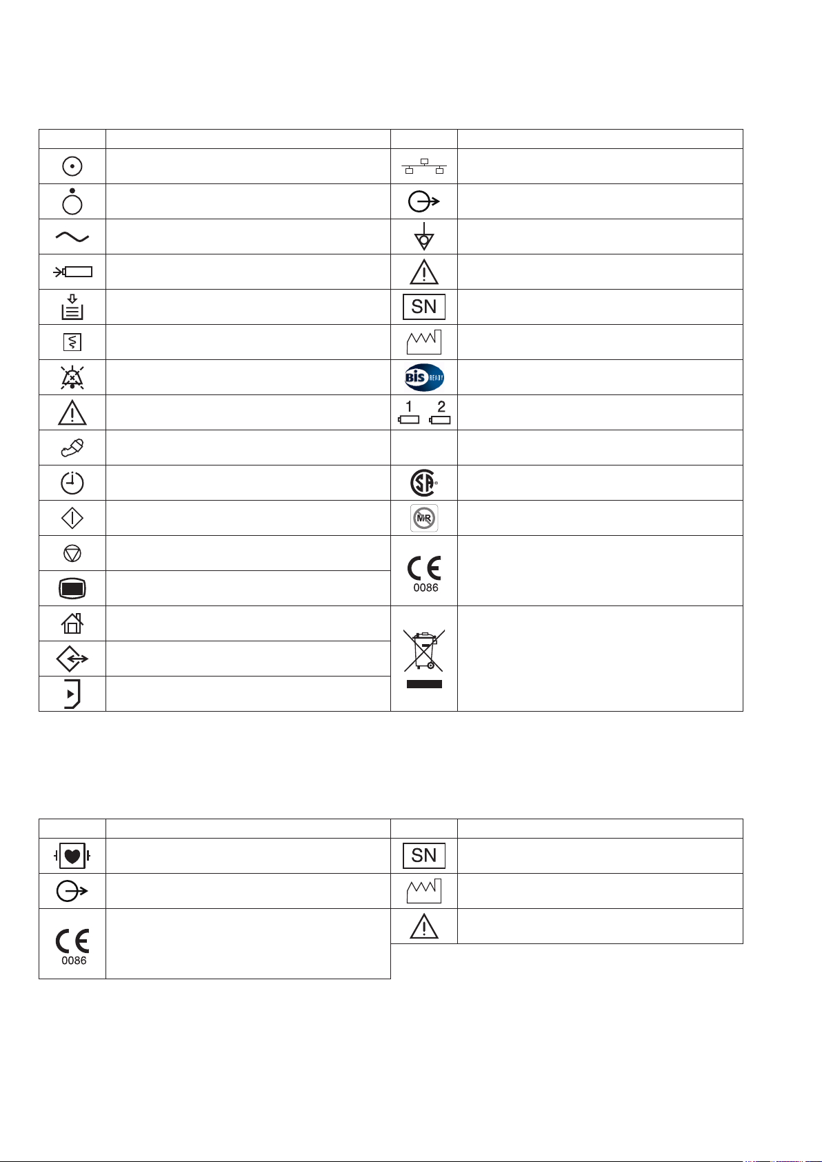
Explanations of the Symbols in this Manual and Instrument
MU-631R/MU-651R/MU-671R Main Unit
Symbol Description Symbol Description
“On” only for a part of instrument Network socket
“Off” only for a part of instrument Output terminal
Alternating current Equipotential terminal
Battery charging Attention, consult operator’s manual
Out of paper Serial number
Record Date of manufacture
Alarm silence BIS processor/BISx
Attention, consult operator’s manual Battery slot 1/Battery slot 2 (MU-631R only)
NIBP
NIBP interval CSA mark*
NIBP start MR unsafe*
NIBP stop
Menu
Home
Data input/output
SD card slot
* The CSA mark and MR unsafe mark only apply to the MU-631RA/MU-651RA/MU-671RA.
** The CE mark and WEEE mark only apply to the MU-631RK/MU-651RK/MU-671RK.
AY Series Input Unit
Symbol Description Symbol Description
ZS
ZS socket
The CE mark** is a protected conformity mark of
the European Community. Products marked with
this symbol comply with the requirements of the
Medical Device Directive 93/42/EEC.
Products marked with this symbol** comply
with the European WEEE directive 2002/96/EEC
and require separate waste collection. For Nihon
Kohden products marked with this symbol,
contact your Nihon Kohden representative for
disposal.
Debrillation-proof type CF applied part Serial number
Output terminal Date of manufacture
The CE mark is a protected conformity mark of
the European Community. Products marked with
this symbol comply with the requirements of the
Medical Device Directive 93/42/EEC.
8 Operator’s Manual BSM-6000
Attention, consult operator’s manual
Page 16
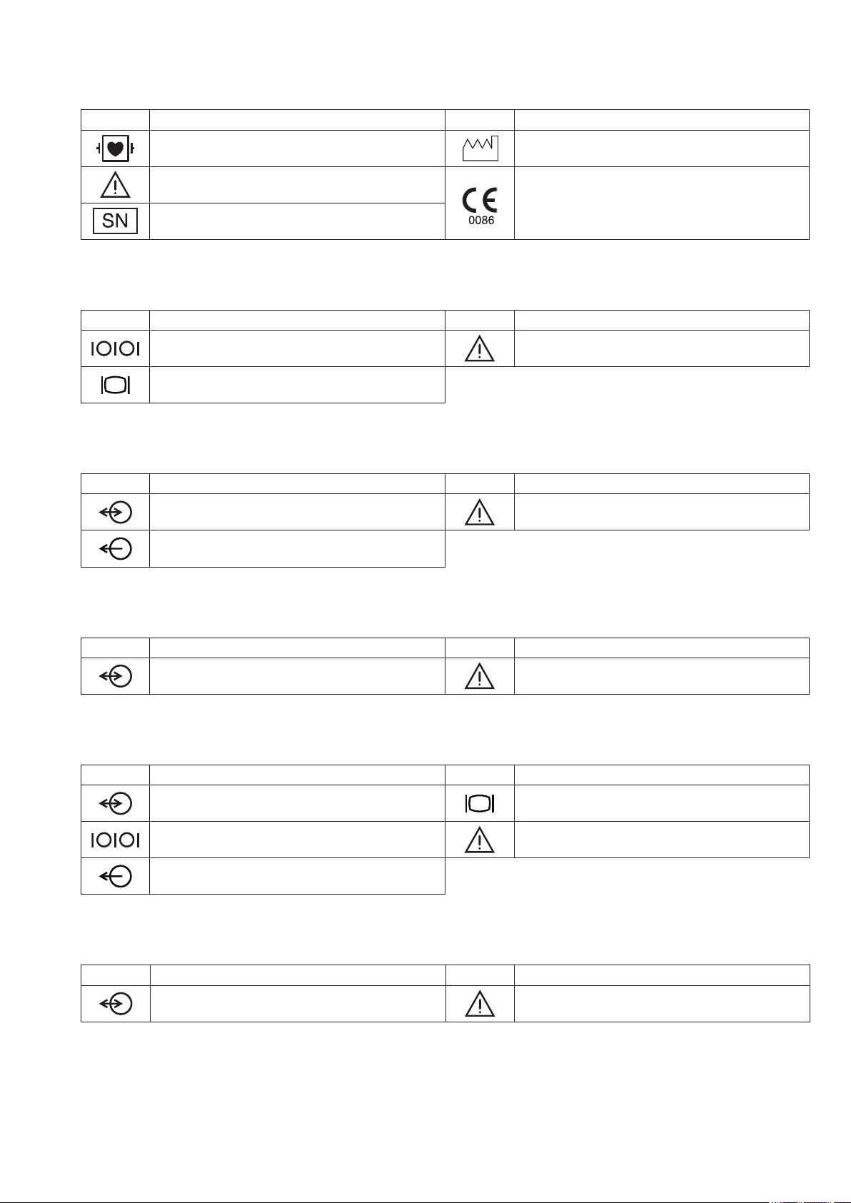
AA-672P/AA-674P Smart Expansion Unit
Symbol Description Symbol Description
Debrillation-proof type CF applied part Date of manufacture
Attention, consult operator’s manual
Serial number
QI-631P Interface
Symbol Description Symbol Description
Serial interface (RS-232C socket) Attention, consult operator’s manual
External display (RGB socket)
QI-632P Interface
Symbol Description Symbol Description
Input/output terminal (USB socket and Multi-link
socket)
Output terminal (Alarm socket)
The CE mark is a protected conformity mark of
the European Community. Products marked with
this symbol comply with the requirements of the
Medical Device Directive 93/42/EEC.
Attention, consult operator’s manual
QI-634P Interface
Symbol Description Symbol Description
Input/output terminal (USB socket and Multi-link
socket)
QI-671P Interface
Symbol Description Symbol Description
Input/output terminal (Multi-link socket) External display (RGB socket)
Serial interface (RS-232C socket) Attention, consult operator’s manual
Output terminal (Alarm socket)
QI-672P Interface
Symbol Description Symbol Description
Input/output terminal (USB socket and Multi-link
socket)
Attention, consult operator’s manual
Attention, consult operator’s manual
Operator’s Manual BSM-6000 9
Page 17
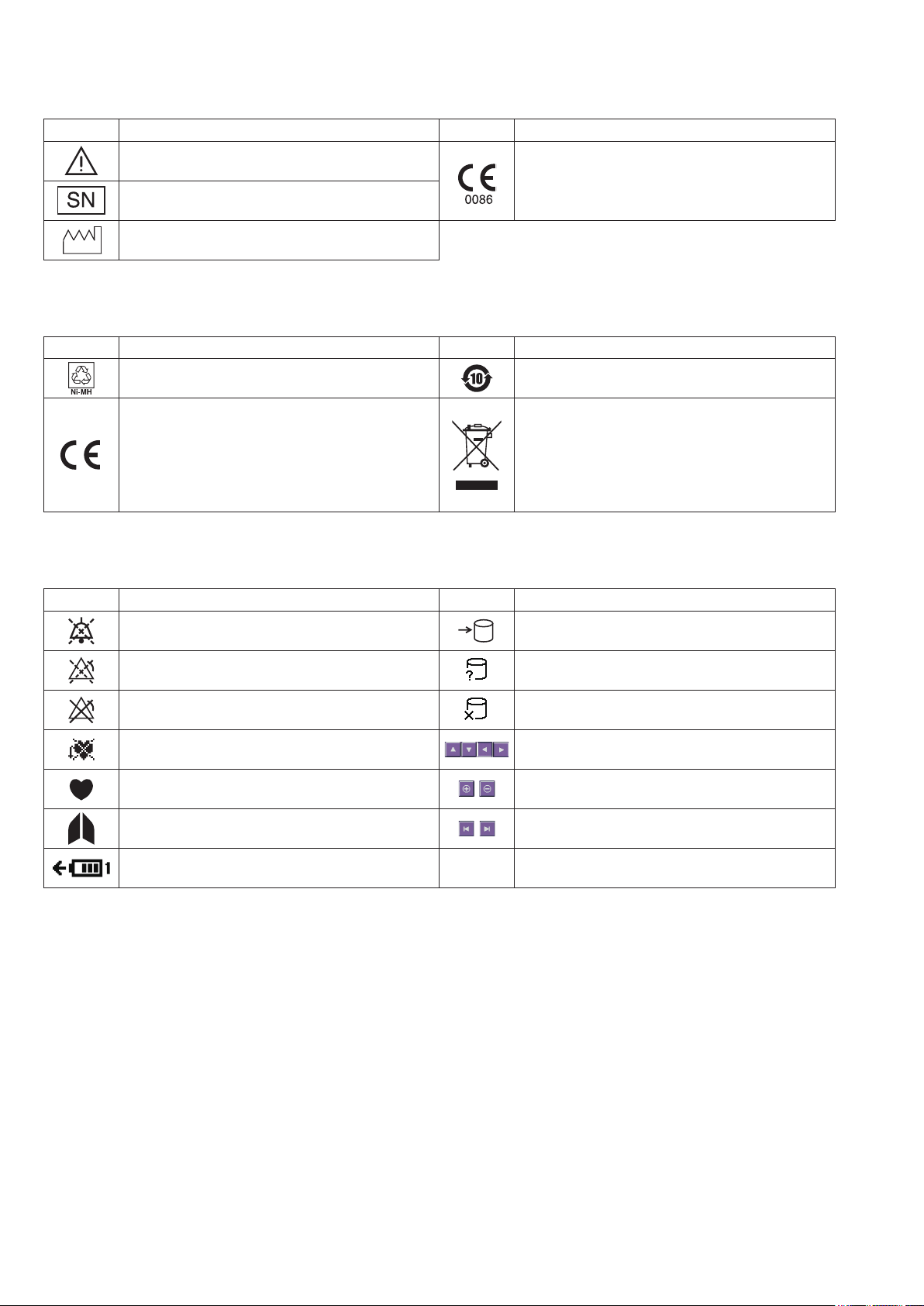
WS-671P Recorder Module
Symbol Description Symbol Description
Attention, consult operator’s manual
Serial number
The CE mark is a protected conformity mark of
the European Community. Products marked with
this symbol comply with the requirements of the
Medical Device Directive 93/42/EEC.
Date of manufacture
SB-671P Battery Pack
Symbol Description Symbol Description
Recycle mark Environmental protection use period: 10 years
Products marked with this symbol comply with
The CE mark is a protected conformity mark of
the European Community. Products marked with
this symbol comply with the requirements of the
Medical Device Directive 93/42/EEC.
the European WEEE directive 2002/96/EEC
and require separate waste collection. For Nihon
Kohden products marked with this symbol,
contact your Nihon Kohden representative for
disposal.
On screen
Symbol Description Symbol Description
Alarm silence Accessing to SD card
Alarm suspended Checking SD card
All alarms off or vital sign alarm limit off SD card failure
Non-paced Adjust setting/Scroll data
QRS/pulse sync mark Zoom in/Zoom out
Respiration sync mark Left end/Right end
Battery status
@
Touch panel calibration
10 Operator’s Manual BSM-6000
Page 18

General Safety Information
WARNING
Never use the monitor in the presence of any
flammable anesthetic gas or high concentration
oxygen atmosphere. Failure to follow this warning
may cause explosion or fire.
WARNING
When the monitor is used with an electrosurgical
unit (ESU), firmly attach the entire area of the ESU
return plate. Otherwise, the current from the ESU
flows into the electrodes of the monitor, causing
electrical burn where the electrodes are attached.
For details, refer to the ESU manual.
WARNING
Before defibrillation, all persons must keep clear of
the bed and must not touch the patient or any
equipment or cord connected to the patient. Failure
to follow this warning may cause electrical shock
or injury.
WARNING
Never use the monitor in a hyperbaric oxygen
chamber. Failure to follow this warning may cause
explosion or fire.
WARNING
When performing defibrillation, discharge as far as
possible from electrodes, patches and any gel,
cream or medicine on the chest of the patient. If
there is a possibility that the defibrillator paddle
could touch these materials, remove them from the
patient. If the defibrillator paddle directly contacts
these materials, the discharged energy may cause
skin burn to the patient.
WARNING
Do not perform defibrillation when the cables are
located between the defibrillator paddles. The
discharged energy may be insufficient.
WARNING
When performing MRI test, remove all electrodes
and transducers from the patient which are
connected to this instrument. Failure to follow this
warning may cause skin burn on the patient. For
details, refer to the MRI manual.
WARNING
After attaching electrodes, probes and sensors on
the patient and connecting cables to the bedside
monitor, check that there is no error messages and
the waveforms and numeric data are appropriately
displayed on the screen. If there is an error
message, or waveform or numeric data is not
appropriate, check the electrodes, probes and
sensor attachment, patient condition and settings
on the bedside monitor and remove the cause.
WARNING
Do not allow the conductive part of the connector
which is connected to the patient to contact other
conductive parts including earth. This causes
leakage current and incorrect measurement value
and leads to wrong diagnosis.
WARNING
Do not use the same monitor for more than one
patient at the same time. Do not connect different
sensors from different patients to the same
monitor.
WARNING
Do not leave the SD card near the patient or in
reach of children.
Operator’s Manual BSM-6000 11
Page 19

CAUTION
Only use Nihon Kohden specified electrodes,
probes, transducers, thermistors and catheters.
Otherwise, the maximum performance from the
monitor cannot be guaranteed.
CAUTION
Make sure that the electrodes and cords attached
to the patient are properly connected to the
monitor. Otherwise, incorrect data may be
displayed and lead to wrong diagnosis.
CAUTION
Turn off the power of mobile phones, small
wireless devices and other devices which produce
strong electromagnetic interference around a
patient (except for devices allowed by the hospital
administrator). Radio waves from devices such as
mobile phones or small wireless devices may be
mistaken as pulse waves and the displayed data
may be incorrect.
CAUTION
Do not reuse disposable parts and accessories.
CAUTION
After the monitor power is turned on, parameter-
related alarms do not function until the parameters
are monitored.
CAUTION
When admitting a new patient, first delete all data
of the previous patient. Otherwise, the data of the
previous patient and new patient will be mixed
together.
CAUTION
If fluids are accidentally spilled into the monitor,
take the monitor out of service and contact your
Nihon Kohden representative. The monitor must be
disassembled, cleaned, dried and tested for safety
and function.
CAUTION
When the “CONNECTOR OFF” message appears
on the screen, check that the connection cords are
connected to the sockets properly. The patient
cannot be monitored and the alarm does not
function while this message is displayed.
When using a ZS-900P transmitter, the
measurement values and displayed waveform on
the bedside monitor and receiving monitor may
differ due to timing delay of the display and other
factors. Be careful when reading the value and
waveform.
CAUTION
The ZS-900P transmitter can only transmit
temperature data from 5 to 45°C (41 to 113°F). Be
careful when reading the value.
NOTE: Operate the monitor on battery power if you cannot confirm the grounding or wiring in your facility.
Using External Instruments
The ZS-900P transmitter can only transmit CO2
data from 0 to 100 mmHg (0 to 13.3 kPa). When
the transmitting data is out of this range, the
receiving monitor displays it as 100 mmHg. Be
careful when reading the value.
CAUTION
CAUTION
WARNING
When connecting an external instrument using an interface or communication cable to the
monitor, some alarms and messages from the external instrument might not be displayed
on the monitor. When the waveform or data is abnormal, check the alarm and message on
the external instrument.
12 Operator’s Manual BSM-6000
Page 20
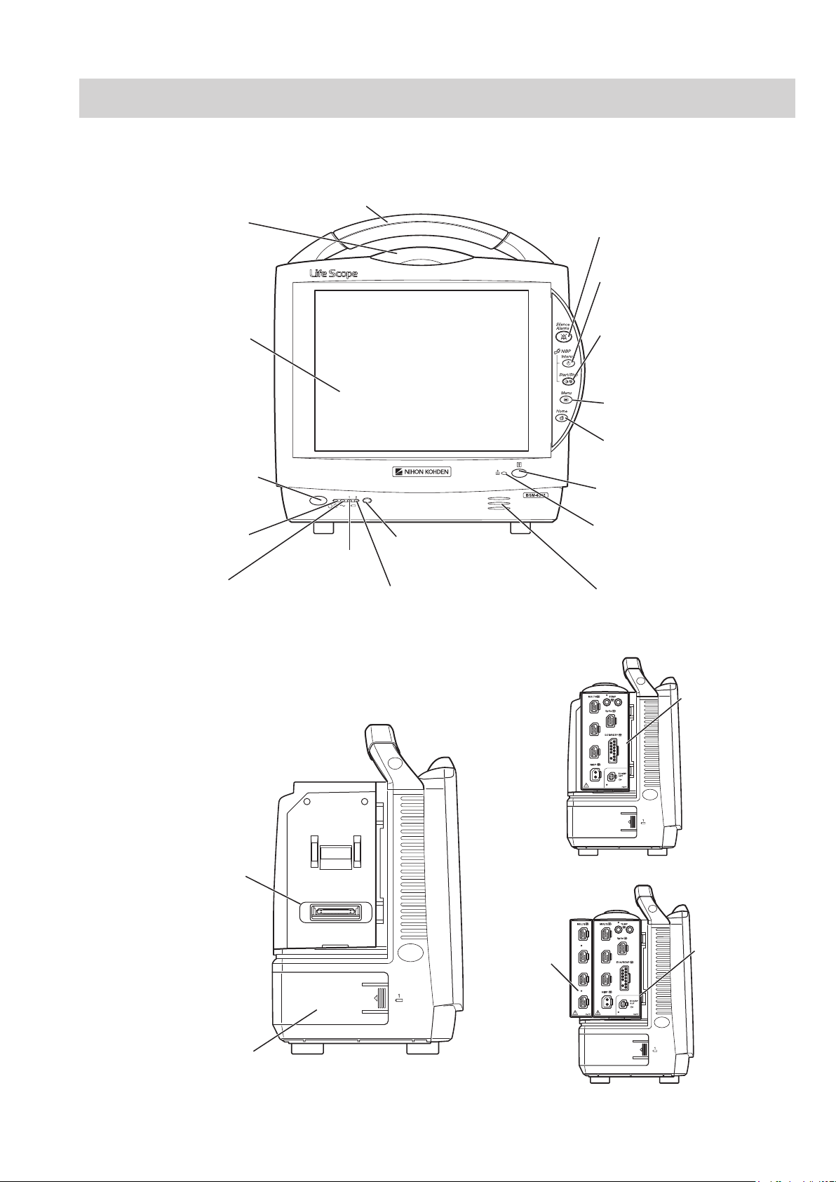
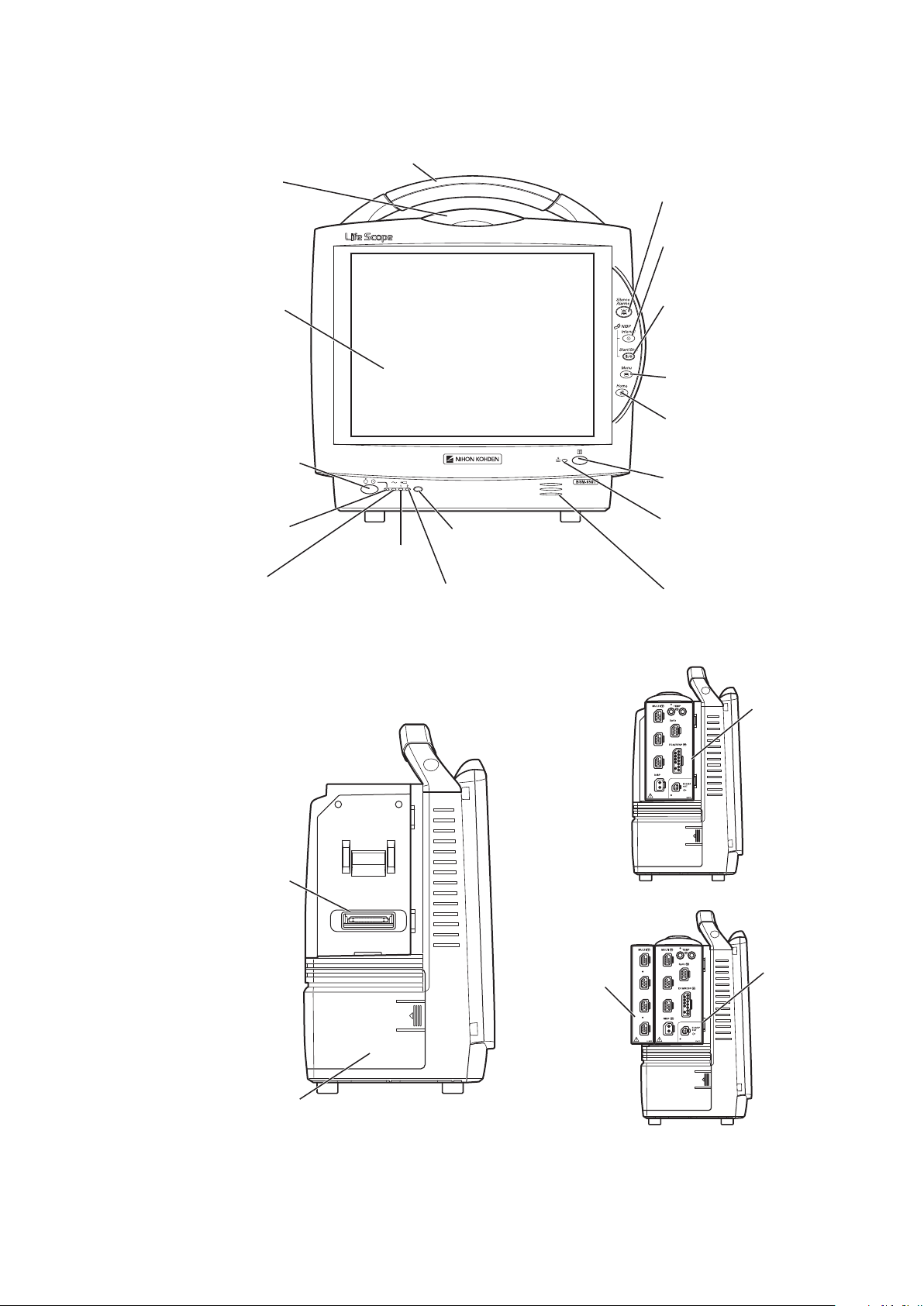
Panel Description
AC power lamp
Lights when the power cord
is connected between the
AC SOURCE socket and AC outlet.
Touch screen
Displays monitoring data.
Touching a key or data on
the screen changes the
displayed screen and settings.
Alarm indicator
Red or yellow lamp blinks, or
yellow or cyan lamps lights
according to the alarm settings.
Green lamp blinks in
synchronization with the patient’s
QRS or pulse.
Handle
For carrying the monitor.
Silence Alarms key
Silences the alarm sound.
NIBP Interval key
Selects NIBP measurement mode.
Pressing this key changes the mode.
NIBP Start/Stop key
Starts NIBP measurement in selected
mode. Pressing the key during
measurement stops measurement.
Menu key
Displays the MENU window.
Home key
Closes all opened windows and
displays the home screen.
Power switch
Press and hold for more
than one second to turn
the monitor power on.
When turning the monitor
power off, press and hold for
more than three seconds.
Power lamp
Lights when the monitor
power is turned on.
Record/Stop key (option)
Press to start or stop recording.
Remote control sensor
Receives an infrared signal
from the remote control.
Error lamp (option)
Blinks when out of paper.
Lights when the recorder
door is open.
Speaker
For alarm and sync sound.
Battery lamp 1
Indicates a battery
status of the battery
in the battery slot 1.
Battery lamp 2
Indicates a battery status of
the battery in the battery slot 2.
Battery pack holder 1
(Battery slot 1)
For an SB-671P battery pack.
Input unit socket
Connects an AY series
input unit.
When the AY-673P input unit installed
AY-673P
When the AY-673P input unit and
AA-674P smart expansion unit are installed
AY-673P
AA-674P
MU-631R Main Unit
Front Panel
Operator’s Manual BSM-6000 13
Left Side Panel
Page 21
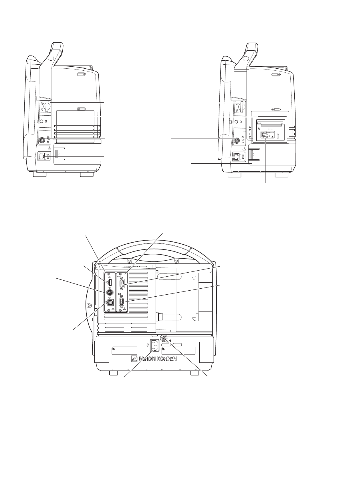
Right Side Panel
When the WS-671P recorder module is installed
Recorder module holder
For the WS-671P recorder module.
SD card slot
For an SD card or program card.
ZS socket
For the ZS-900P* transmitter.
Network socket
Connects to monitor network system
via the network separation unit.
Battery pack holder 2 (Battery slot 2)
For an SB-671P battery pack.
* ZS-900P transmitter is not available for BSM-6000A series.
RGB socket (QI-631P)
Outputs the RGB video signal.
Connects to the slave display.
QI-631P interface socket
Connects the QI-631P interface.
QI-632P/QI-634P interface socket
Connects the QI-632P or QI-634P
interface.
AC SOURCE power cord socket
For the AC power cord.
Equipotential grounding terminal
For an equipotential grounding lead.
USB socket (QI-632P/QI-634P)
Connects a mouse or bar code
reader.
Multi-link socket
(QI-632P/QI-634P)
Connects a QF series
interface, IF series
communication cable or
multi-link cable of an
external unit.
RS-232C socket (QI-631P)
Not available.
Alarm socket (QI-632P)
Connects a YJ-672P nurse call
cable.
Rear Panel
Example shows the QI-631P and QI-632P interfaces installed.
14 Operator’s Manual BSM-6000
Page 22
MU-651R/MU-671R Main Unit
AC power lamp
Lights when the power cord
is connected between the
AC SOURCE socket and AC outlet.
Touch screen
Displays monitoring data.
Touching a key or data on
the screen changes the
displayed screen and settings.
Alarm indicator
Red or yellow lamp blinks, or
yellow or cyan lamps lights
according to the alarm settings.
Green lamp blinks in
synchronization with the patient’s
QRS or pulse.
Handle
For carrying the monitor.
Silence Alarms key
Silences the alarm sound.
NIBP Interval key
Selects NIBP measurement mode.
Pressing this key changes the mode.
NIBP Start/Stop key
Starts NIBP measurement in selected
mode. Pressing the key during
measurement stops measurement.
Menu key
Displays the MENU window.
Home key
Closes all opened windows and
displays the home screen.
Power switch
Press and hold for more
than one second to turn
the monitor power on.
When turning the monitor
power off, press and hold for
more than three seconds.
Power lamp
Lights when the monitor
power is turned on.
Record/Stop key (option)
Press to start or stop recording.
Remote control sensor
Receives an infrared signal
from the remote control.
Error lamp (option)
Blinks when out of paper.
Lights when the recorder
door is open.
Speaker
For alarm and sync sound.
Battery lamp 1
Indicates a battery
status of the battery
in the battery slot 1.
Battery lamp 2
Indicates a battery status of
the battery in the battery slot 2.
When the AY-673P input unit installed
When the AY-673P input unit and
AA-674P smart expansion unit are installed
AY-673P
AY-673P
AA-674P
Battery pack holder
For an SB-671P battery pack.
Input unit socket
Connects an AY series
input unit.
Front Panel
Operator’s Manual BSM-6000 15
Left Side Panel
Page 23
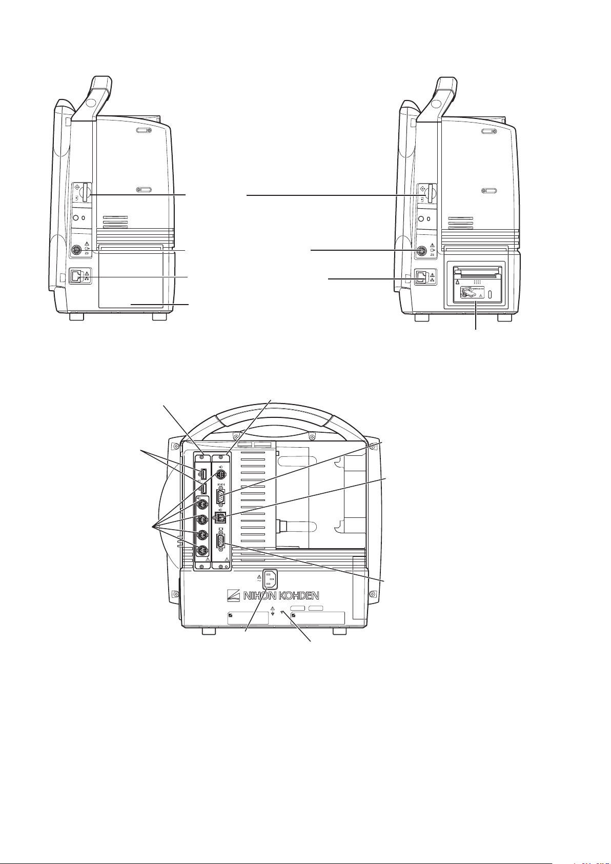
Right Side Panel
When the WS-671P recorder module is installed
Recorder module holder
For the WS-671P recorder module.
SD card slot
For an SD card or program card.
ZS socket
For the ZS-900P* transmitter.
Network socket
Connects to monitor network system
via the network separation unit.
* ZS-900P transmitter is not available for BSM-6000A series.
RGB socket
Outputs the RGB video signal.
Connects to the dual display or
slave display.
QI-671P interface socket
Connects the QI-671P interface.
QI-672P interface socket
Connects the QI-672P interface.
AC SOURCE power cord socket
For the AC power cord.
Equipotential grounding terminal
For an equipotential grounding lead.
USB sockets
Connects a
mouse or bar code
reader.
Multi-link sockets
Connects a QF series
interface, IF series
communication cable
or multi-link cable of
an external unit.
RS-232C socket
Not available.
Alarm socket
Connects a YJ-672P nurse call
cable.
Rear Panel
16 Operator’s Manual BSM-6000
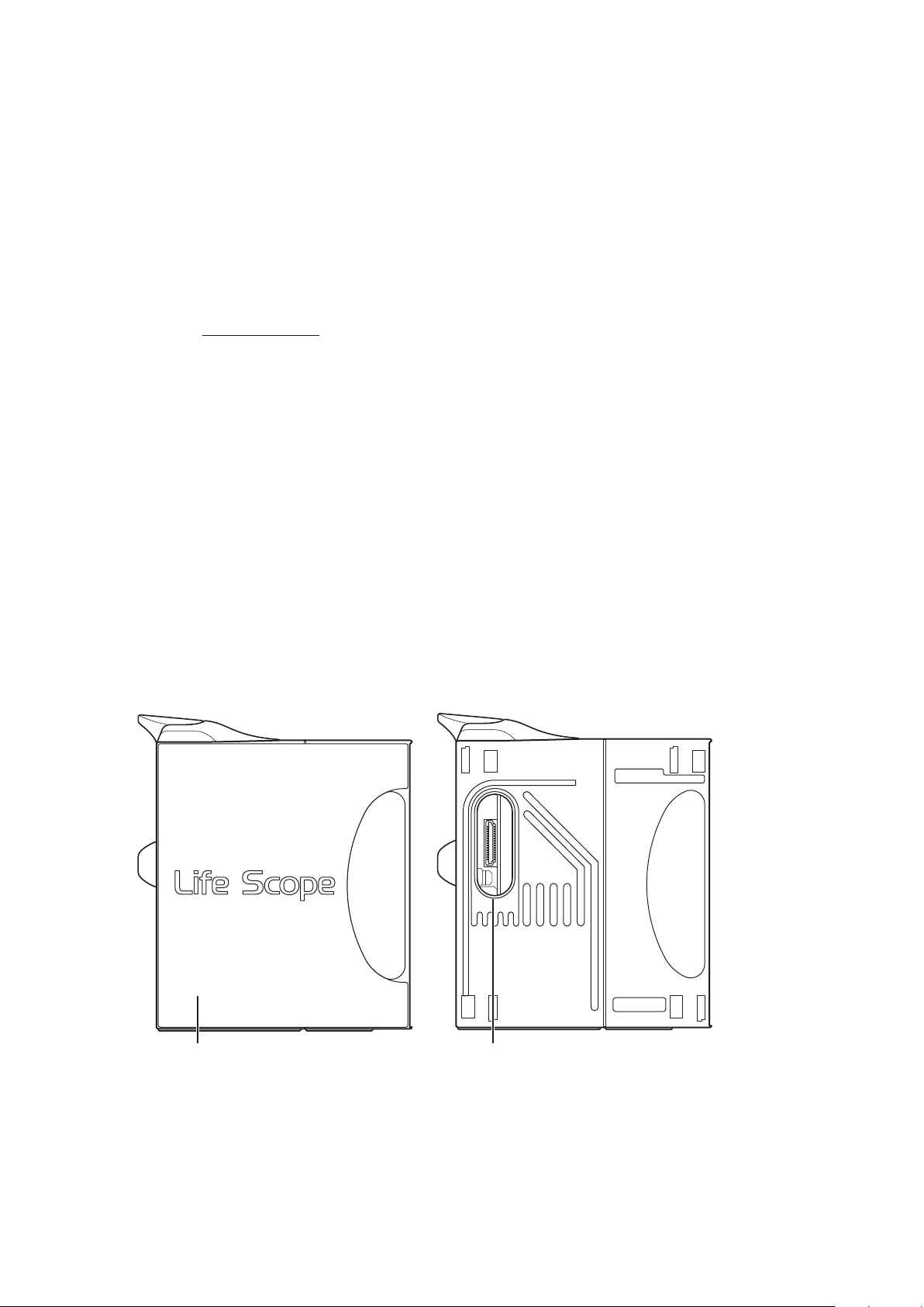
Page 24
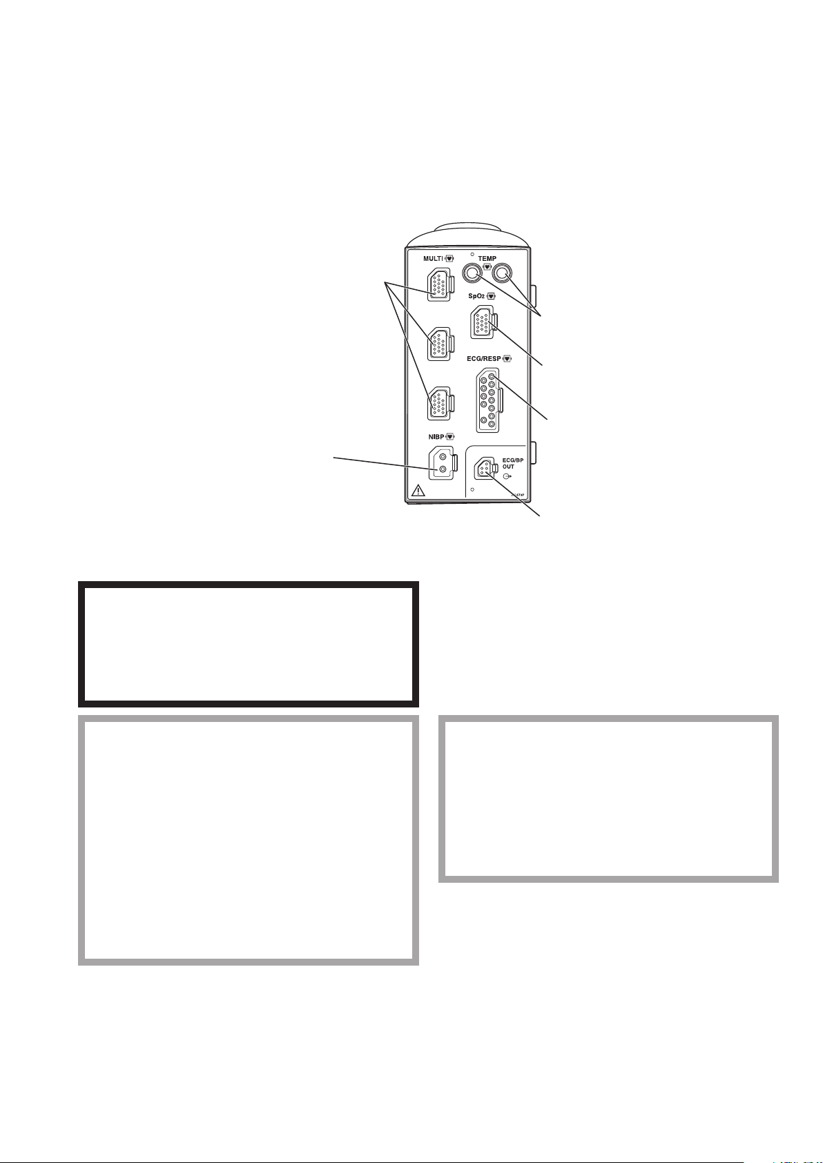
AY-631P/AY-633P/AY-651P/AY-653P/AY-660P/AY-661P/AY-663P/AY-671P/AY-673P Input
NIBP socket
Connects to the air hose.
MULTI socket
Connects to the connection cord of
the parameter to be monitored
(IBP, temperature, CO, CO2, O2,
respiration by thermistor method,
SpO2-2 (AY-661P/663P/671P/
673P only) or BIS). The type of
parameter is automatically recognized.
TEMP socket
Connects to the temperature probe cord.
SpO2 socket
Connects to the SpO2 connection cord.
ECG/RESP socket
Connects to the ECG connection cord.
ECG/BP OUT socket
Outputs 100 mmHg/V IBP waveform and
1 mV/V ECG waveform and heart rate trigger
by using the YJ-910P or YJ-920P ECG/BP
output cable. These analog signals can be used
as the synchronization signal for other
equipment, such as IABP.
Unit
Front Panel
AY-660P: One TEMP socket, one MULTI socket, no ECG/BP OUT socket
AY-631P/AY-651P/AY-661P/AY-671P: Two TEMP sockets, one MULTI socket
AY-633P/AY-653P/AY-663P/AY-673P: Two TEMP sockets, three MULTI sockets
Example is AY-673P input unit.
When performing defibrillation during cardiac
output monitoring, never touch the CO connection
cord. The discharged energy may cause electrical
shock or injury.
When using the output signal from the monitor as
the synchronization signal for other equipment
such as an IABP (intra-aortic balloon pump) or
defibrillator:
• Set the timing of the IABP by checking the
waveform on the IABP screen.
• Check the condition of the bedside monitor at all
times. The output signal may become unstable.
• Check that the delay time of the output signal is
within the range of the connected equipment.
WARNING
CAUTION
CAUTION
Only a Nihon Kohden defibrillator can use the
output signal from the monitor as a
synchronization signal. Check that the delay time
of the output signal (heart rate trigger 20 ms
maximum) is within the range of the connected
defibrillator.
Operator’s Manual BSM-6000 17
Page 25
NOTE:
When the side panel is removed
Side panel
Remove to attach an AA-672P or AA-674P
smart expansion unit.
Smart expansion unit socket
Connects an AA-672P or AA-674P smart expansion unit.
• When using an IBP waveform as a synchronization signal for other equipment, connect
the IBP line to the MULTI socket on the input unit. The IBP waveform that is used for the
synchronization signal depends on the “IBP ANALOG OUT” setting in the SYSTEM SETUP
window.
- When “IBP ANALOG OUT” is set to “FIXED POSITION”:
The IBP line connected to the top MULTI socket on the input unit is used.
- When “IBP ANALOG OUT” is set to “HIGHEST PRIORITY LABEL” :
When more than one IBP waveform is acquired, the IBP waveform of the highest priority
label is used.
IBP label priority:
ART > ART2 > RAD > DORS > AO > FEM > UA > LVP > P1 > P2 > P3 > P4 > P5 > P6 > P7
• Analog ECG, analog BP and heart rate trigger output are not available when an AY-660P input
unit is used.
• The output signal from the ECG/BP OUT socket may become unstable in the following
conditions.
- Electrode is dry or detached.
- Electrode lead is damaged or disconnected from the electrode.
- Electrode lead is pulled.
- AC interference or EMG noise superimposed.
- Air bubbles or blood clog in the circuit for monitoring IBP.
- Cord or cable is disconnected or damaged.
• All instruments which are to be connected to the ECG/BP OUTPUT socket must use a YJ-
910P or YJ-920P ECG/BP output cable and comply with the IEC 60601-1 safety standard for
medical equipment.
Left Side Panel
18 Operator’s Manual BSM-6000
Page 26
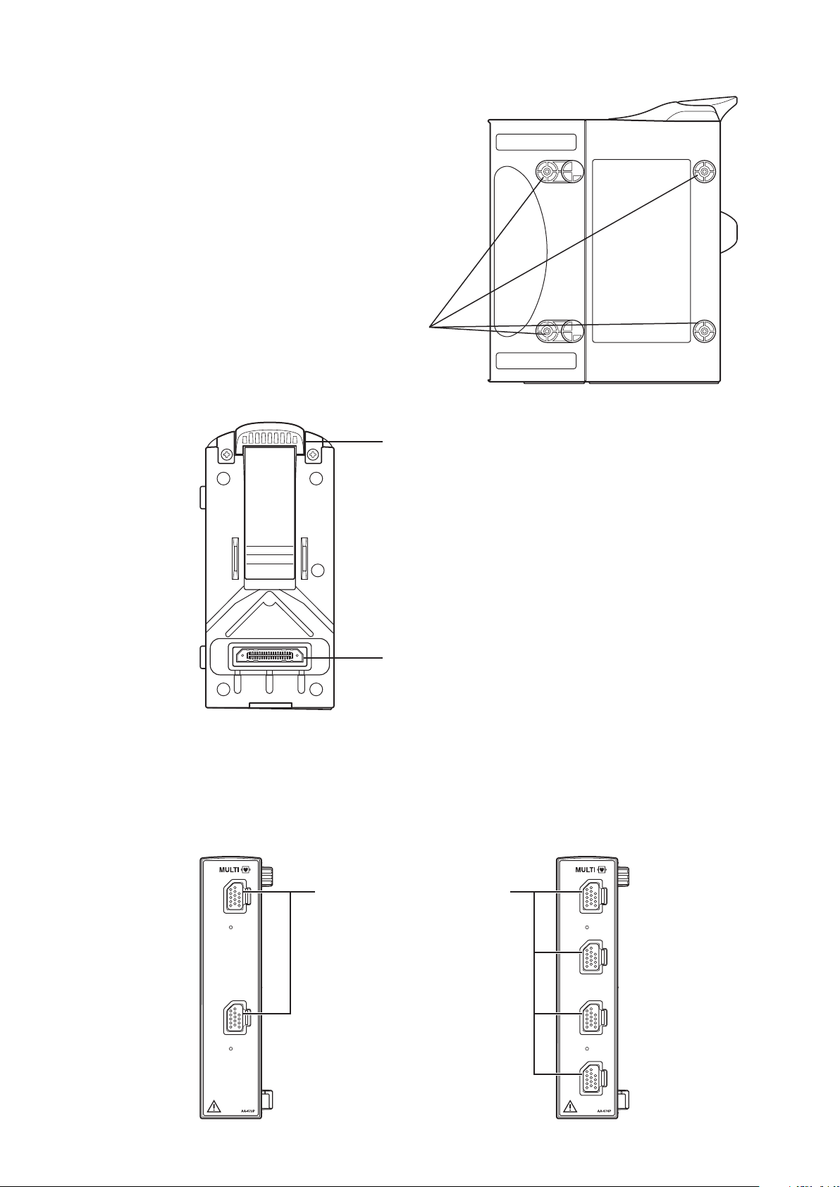
Right Side Panel
Tabs
Match the tabs on the input unit to the slots
on the bedside monitor.
Input unit socket
For connecting a bedside monitor.
Lock release lever
Lift up the lever to remove the
input unit from the bedside monitor.
MULTI socket
Connects to the connection cord of
the parameter to be monitored
(IBP, temperature, CO, CO2, O2,
respiration by thermistor method,
SpO2-2 (AY-661P/663P/671P/
673P only) or BIS). The type of
parameter is automatically recognized.
Rear Panel
AA-672P/AA-674P Smart Expansion Unit
Front Panel
AA-672P AA-674P
Operator’s Manual BSM-6000 19
Page 27
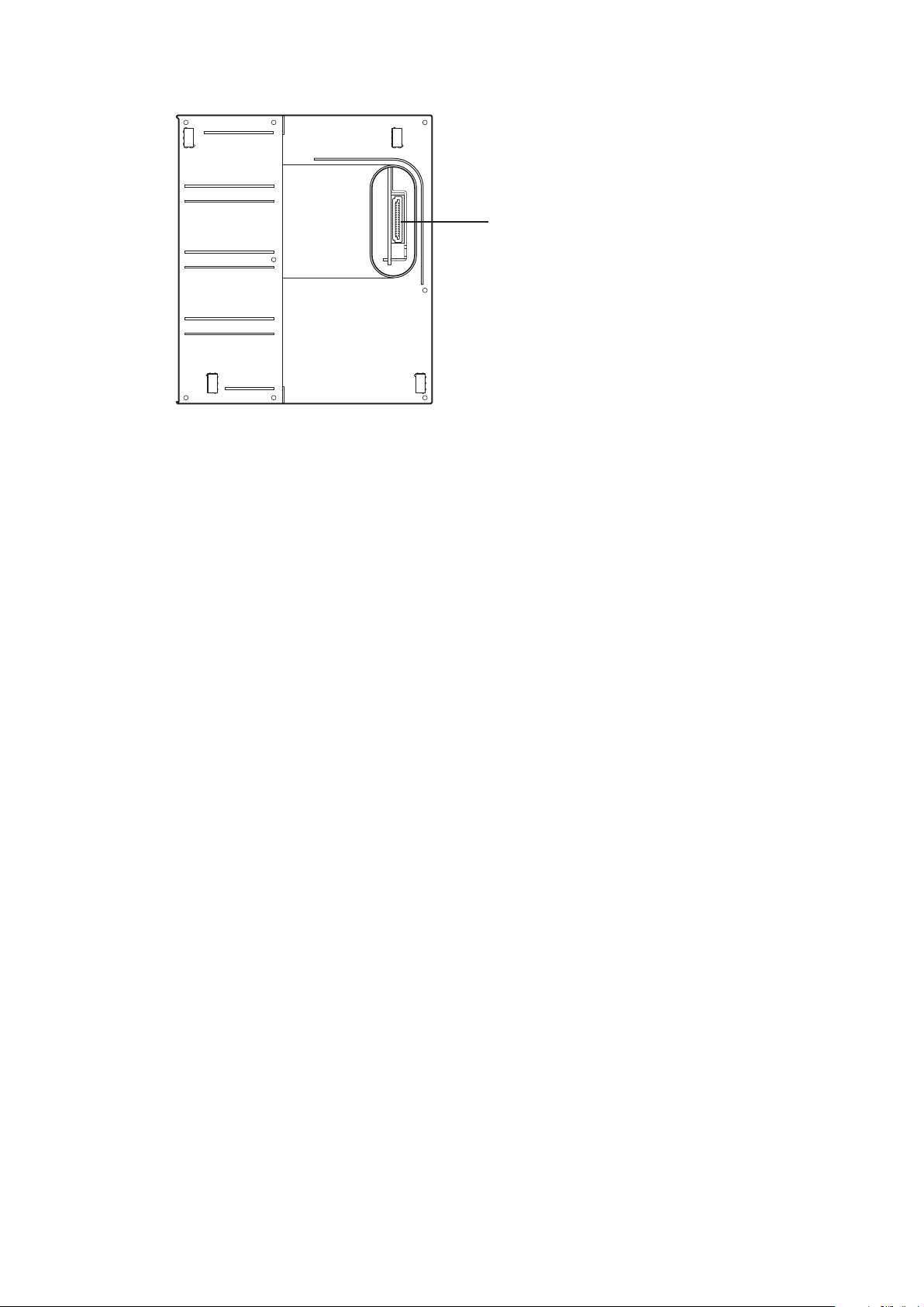
Right Side Panel
Connector
Connects an AY-631P, AY-633P, AY-651P, AY-653P,
AY-661P, AY-663P, AY-671P or AY-673P input unit.
20 Operator’s Manual BSM-6000
Page 28

Installation
10 cm
5 cm Rear Panel
5 cm
Side Panel
General
The monitor must be installed by qualied personnel. Details are in the Administrator’s Guide.s Guide. Guide.
WARNING
Only use the provided power cord. Using other
power cords may result in electrical shock or injury
to the patient and operator.
WARNING
Connect only the specified instrument to the
monitor and follow the specified procedure. Failure
to follow this warning may result in electrical shock
or injury to the patient and operator, and cause fire
or instrument malfunction.
CAUTION
Only use the specified stand, cart or equipment for
installing the monitor and instruments. Using non-
specified equipment may result in the instruments
falling and causing injury.
WARNING
When several medical instruments are used
together, ground all instruments to the same one-
point ground. Any potential difference between
instruments may cause electrical shock to the
patient and operator.
WARNING
• Do not install the monitor and optional units
above the patient.
• Only use the specified tools or equipment when
installing the monitor and units. Failure to follow
this warning may result in the monitor or unit
falling and injuring the patient.
CAUTION
When not using the specified cart, carefully set the
monitor to prevent it from falling off or tipping over.
CAUTION
Before connecting or disconnecting instruments,
make sure that each instrument is turned off and
the power cord is disconnected from the AC
socket. Otherwise, the patient or operator may
receive electrical shock or injury.
Make sure that there is more than 5 cm of space between the monitor and the wall for adequate
ventilation. When the monitor is surrounded, make sure that there is about 10 cm of space above the
monitor for ventilation so that the operating temperature does not exceed 40°C (104°F).
Operator’s Manual BSM-6000 21
Page 29
Grounding the Monitor
Medically-used room
Patient Environment
Outside the Patient Environment
Non-medically used room
Sub display
(IEC 60601-1 complied or
using the isolation transformer
complied to IEC 60601-1)
Sub display
(IEC 60601-1 complied or
using the isolation transformer
complied to IEC 60601-1)
External
instruments
(IEC 60601-1 complied)
Central monitor
Network printer
(IEC xxx complied)
Remote controller
RY-910PA
Interface
QF series
Communication
cable
IF series
External
instruments
(IEC 60601-1 complied)
Mouse
Bar code reader
Smart
expansion unit
AA-672P/674P
Hyper isolation
transformer
QW-100Y
(HIT-100)
Input unit
AY-631P/633P
AY-651P/653P
AY-661P*/663P*
AY-671P/673P
Recorder
module
WS-671P
Transmitter
ZS-900P
Wireless LAN
station
QI-320PA
BSM-6301/6501/6701
Interface
QI-632P/634P
(For MU-631R)
QI-672P
(For MU-651R/671R)
Interface
QI-631P
(For MU-631R)
Interface
QI-671P
(For MU-651R/671R)
Main unit
MU-631R/
671R/651R
Input unit
AY-660P*
Multigas unit
GF-110PA/210R*
Multigas/Flow unit
GF-120PA*/220R*
Neuro unit
AE-918P*
* These units are not available for BSM-6000A series.
When more than one electrical instrument is used, there may be electrical potential difference between
the instruments. The potential difference between the instruments may cause current to ow to the patient
connected to the instruments, resulting in electrical shock (micro shock).
When equipotential grounding is required, connect the equipotential ground terminal on the instrument
to the equipotential ground terminal on the wall (equipotential grounding system) with the equipotential
grounding lead (potential equalization conductor).
NOTE:
• For details on connecting an external instrument to the monitor, contact your Nihon Kohden
representative.
• Leakage current may increase when interconnecting many medical instruments to the monitor.
Environment for External Instruments
Use external instruments in the following environment.
22 Operator’s Manual BSM-6000
Page 30

Warnings and Cautions for Connecting the Monitor to a Network
WARNING
Install all network devices, including printer and
hubs, outside the patient environment (IEC 60601-
1-1). If they are installed inside the patient
environment, the patient or operator may receive
electrical shock or injury. For installation, contact
your Nihon Kohden representative.
WARNING
Connect the monitor to network as specified.
Otherwise the patient and operator may receive
electrical shock or injury. To connect the network,
contact your Nihon Kohden representative.
WARNING
Do not use a damaged network cable. The patient
or operator may receive electrical shock when the
damaged part is touched.
WARNING
Check the software version number of the monitor
before connecting it to the network. Different
software versions have different communication
methods. More than one communication method in
a network may cause communication failure. For
details, refer to the Network and System
Installation Guide.
WARNING
In a network where this monitor is connected,
connect only the specified instruments.
Unspecified instruments may cause electrical
shock or injury to the patient and operator or
cause instrument malfunction, instrument stop, or
data loss.
CAUTION
When the monitor is connected to a central
monitor network, set the Bed Name (Bed ID) and
Group Name on the monitor. Otherwise, the default
settings are used for the bed name and group
name and the bed may be incorrectly identified on
the central monitor.
CAUTION
The network must be managed by the network
administrator. Make sure that each monitor in the
network has a different IP address. Otherwise,
data communication cannot be performed properly.
When adding a monitor to an already operating
network, set the IP address on the monitor before
connecting the monitor to the network.
Operator’s Manual BSM-6000 23
Page 31

Inserting and Removing the Battery Packs
This monitor can hold two battery packs. Insert the battery pack to the battery slot 1 or/and battery slot 2.
NOTE:
• Only use the SB-671P battery pack.
• The procedure for inserting and removing the battery packs is the same for
BSM-6301 and BSM-6501/BSM-6701 bedside monitors even though the
battery slot position and battery cover shape are different.
Battery slot 1
Battery slot 1
Battery slot 2
Battery slot 2
Inserting the Battery Pack
1. Remove the battery cover by pressing the tab on the battery cover and slide the
cover off.
Battery coverBattery cover
Battery packBattery lever Battery packBattery lever
2. Insert the battery pack with the label (black) facing up in the battery slot.
3. Attach the battery cover.
24 Operator’s Manual BSM-6000
Page 32

Battery leverBattery lever
Removing the Battery Pack
1. Remove the battery cover by pressing the tab on the battery cover and
slide the cover off.
Battery coverBattery cover
2. Press the battery lever to release the lock.
3. Pull out the battery pack from the battery slot.
4. Attach the battery cover.
Operator’s Manual BSM-6000 25
Page 33

Inserting and Removing the Input Unit
The input unit can be inserted or removed from the monitor. When the patient is changed or moved to a
different location, insert or remove the input unit.
Inserting the Input Unit
1. Put the input unit into the rear of the monitor so that the four tabs go into the
four slots.
2. Slide the input unit all the way into the monitor until it clicks into place.
Input unit socket
Input unit socket
Tabs
Tabs
Slots
Slots
Lock release leverLock release lever
Connector
Connector
Removing the Input Unit
CAUTION
When inserting or removing the input unit from the monitor, be careful not to drop it.
Slide out the input unit while pulling up the lock release lever.
26 Operator’s Manual BSM-6000
Page 34

Loading Recording Paper
When using the WS-671P recorder module, load the recording paper as follows.
Do not touch the thermal head inside the recorder module. The thermal head may be
damaged by static electricity or become dirty and cause printing failure.
Door release leverDoor release lever
CAUTION
1. Move the door release lever in the direction of the arrow ( ) to release the lock.
MarkMark
2. Open the recorder door. Set the recording paper (FQW50-2-100) inside the recorder
so that the detection mark (small black square on corner) of the paper is on the right
side.
3. Draw out one page of paper toward you and close the recorder door. If the out of
paper lamp is still lit, the recorder door is not closed properly.
Operator’s Manual BSM-6000 27
Page 35

Turning the Monitor On or Off
Turning the Monitor On
The monitor can operate on either battery or AC power. When the monitor is installed and the power
cord is connected, the AC power lamp lights. When a battery pack is installed and the power cord is
disconnected or there is a sudden power failure, the monitor automatically switches to battery power. The
monitor can operate for about 90 minutes (BSM-6301/BSM-6501) or 60 minutes (BSM-6701) with a new
fully charged battery pack when:
• Used in normal temperature.
• Recorder is stopped.
• No alarm occurs.
• Monitoring ECG, respiration (impedance) and SpO2.
• <POWER SAVING MODE> on the SYSTEM SETUP window is set to ON.
• <SYNC SOUND VOLUME> on the VOLUME window is set to OFF.
• NIBP measurement interval is 15 minutes.
• QI-671P and QI-672P interfaces or QI-631P and QI-632P or QI-634P interfaces are installed in the
monitor.
Check Before Turning On the Power
Check the following items before turning on the power.
• Enough electrodes and electrode leads are ready.
• Cleaned and sterilized sensors and transducers are ready.
• Power cord is connected properly.
• Equipotential grounding lead is connected properly when equipotential grounding is required.
• All cables are connected properly.
• Enough recording paper in the recorder (when using an optional recorder).
• Fully charged battery pack is installed in the monitor in case of a sudden power failure.
• No scratches, damage or dirt on the monitor.
• No damage to the keys and panels.
• No damage to the power cord.
• No damage to the electrode leads, transducers, probes and cables.
• The monitor is not in a wet place.
NOTE: When the AC power lamp is not lit, check the power cord connection.
The AC power lamp does not light when there is not enough current to each
unit.
When the power cord is connected between the bedside monitor and AC outlet and the
AC power lamp lights, press the [Power] switch on the front panel to turn the power
on. The power lamp and the AC power lamp light and self check starts. When the
Lit LitLit Lit
28 Operator’s Manual BSM-6000
check is complete, the home screen appears.
NOTE: Even though the position of symbol marks for the lamps are different on
BSM-6301 and BSM-6501/BSM-6701 bedside monitors, the function and the
position of lamps are the same.
The power can also be turned on by pressing the [POWER] button on the remote
control.
Page 36

CAUTION
When the monitor is turned on, check that a single beep sounds and the red, yellow, cyan
and green alarm indicator lamps blink once. This shows that the alarm is functioning
properly.
When the monitor power is turned on, alarms are suspended while the monitor is waiting for the
electrodes and probe to be attached to the patient. The monitoring starts when the connection cord is
connected to the socket on the monitor and the electrodes or probe are attached to the patient. The alarm
activates when one of the following occurs:
• at least one parameter is measured and a value is displayed (when AUTO is selected for <ALARM
ACTIVATION DELAY> on the ALARM window of the SYSTEM SETUP window)
• ECG, SpO2 or IBP is continuously monitored for the selected time (when 1 min, 2 min or 3 min is
selected for <ALARM ACTIVATION DELAY>)
• NIBP is measured (when 1 min, 2 min or 3 min is selected for <ALARM ACTIVATION DELAY>)
When <AUTO ADMIT> in the SYSTEM CONFIGURATION screen is set to ON and the monitor power
is turned on more than 30 minutes after turning the power off, the stored data in the monitor is deleted.
When the monitor is turned on in less than 30 minutes after turning power off, the stored data is not
deleted and monitoring continues. When <AUTO ADMIT> in the SYSTEM CONFIGURATION screen
is set to OFF, the message appears asking whether monitoring a new patient or not. The factory default
setting is ON.
Check After Turning On the Power and During Monitoring
To start monitoring safely and properly, check the following items after turning on the power. If any
problem is detected, take the proper countermeasure according to the troubleshooting and maintenance
sections.
• There is no re, smoke or smell.
• The monitor is not too hot.
• The power lamp and other lamps light.
• Alarm indicators (red, yellow, cyan and green lamps) blink once and a beep sounds.
• The start up screen and the home screen appears.
• No error message is displayed on the screen.
• The time on the screen is correct.
• The monitor does not affect surrounding equipment.
• The data and waveforms are displayed properly.
• Keys and switches operate properly.
• The touch keys function properly and the key clicking sound is generated.
• Alarm functions properly.
• Alarm sound can be heard.
• Alarm sound volume setting is appropriate.
• There is no trouble in recording (when using an optional recorder).
• Sound can be heard from the monitor.
Operator’s Manual BSM-6000 29
Page 37

Power and Battery Status Indications
Battery slot No.
Battery slot 1
Battery slot 2
Battery slot 1
Battery slot 2
BSM-6301 BSM-6501/BSM-6701
Remaining battery power
more than 90%
more than 60%
more than 40%
more than 25%
less than 25%
Battery operation
Operating on battery
Battery is being charged
Power and battery status are indicated by four lamps on the bedside monitor. A discharged battery is also
indicated by battery marks, screen message and alarm.
NOTE:
• When charging the battery pack with the monitor power turned off, check that the power
lamp and battery charging lamp light. If the lamps do not light even when the power cord is
connected and the battery pack is inserted, turn the power on, check that the battery charging
lamp is blinking or lit, then turn the power off.
• Even though the position of symbol marks for the lamps are different on BSM-6301 and BSM-
6501/BSM-6701 bedside monitors, the function and the position of lamps are the same.
• Operating on AC power and battery pack is fully charged or there is no battery
Power lamp: Lit
AC power lamp: Lit
Battery lamp 1: Lit or off
Battery lamp 2: Lit or off
• Operating on AC power and battery pack is being charged
Power lamp: Lit
AC power lamp: Lit
Battery lamp 1: Slow blinking (once every 2 seconds) or off
Battery lamp 2: Slow blinking (once every 2 seconds) or off
• Operating on AC power when battery pack is damaged
Power lamp: Lit
AC power lamp: Lit
Battery lamp 1: Rapid blinking (4 times per second) or off
Battery lamp 2: Rapid blinking (4 times per second) or off
30 Operator’s Manual BSM-6000
Page 38

• Operating on battery power
Power lamp: Lit
AC power lamp: Off
Battery lamp 1: Lit* or off
Battery lamp 2: Lit* or off
* When two battery packs are used and when the battery pack which is not used is
fully charged
• Operating on battery power and battery pack is damaged
Power lamp: Lit
AC power lamp: Off
Battery lamp 1: Rapid blinking (4 times per second) or off
Battery lamp 2: Rapid blinking (4 times per second) or off
Screen indication: “BATTERY WEAK” message
Alarm indication: Continuous “bing bong” sound and blinking yellow alarm
• No monitoring and charging battery pack
Power lamp: Off
AC power lamp: Lit
Battery lamp 1: Slow blinking (once every 2 seconds) or off
Battery lamp 2: Slow blinking (once every 2 seconds) or off
Battery Pack Handling and Operation OperationOperation
WARNING
• Never short-circuit the + and − terminals on the
battery pack. It may cause overheating and fire.
• Keep the battery pack away from fire. It may
explode.
• Do not damage, disassemble, drop or give
impact to the battery pack.
• Never use the battery pack on unspecified
instruments.
• Never charge the battery pack on unspecified
instruments.
• Never install the battery pack with the wrong
polarity.
• Keep the battery pack away from patients.
CAUTION
Do not expose the battery pack to direct sunlight
or leave in a high temperature place. The lifetime
of the battery pack may be shortened, the
performance of the battery pack may be degraded
and the battery pack may leak.
WARNING
If the battery pack is damaged and the substance
inside the battery pack contacts the eyes or skin,
wash immediately and thoroughly with water and
see a physician. Never rub your eyes, because you
may lose your eyesight.
WARNING
• Do not immerse the battery pack in water. The
battery pack may heat up and rust and the
substance inside the battery pack may leak.
• Do not leave the battery pack unused for more
than about two years. The battery pack may leak.
CAUTION
Do not use a battery pack with a damaged cover.
The operator may receive electrical shock.
Operator’s Manual BSM-6000 31
Page 39

CAUTION
Do not tilt the monitor when removing the battery
pack from the monitor. If the lock release lever is
lifted while the monitor is tilted, the battery pack
falls out of the monitor and may injure the patient
or operator.
CAUTION
Do not leave the battery pack near the patient or in
reach of children.
CAUTION
Do not use a battery pack which is past the
expiration date written on the label.
NOTE: Be careful when handling the fully charged battery pack. The battery pack heats up to
about 60°C (140°F).
CAUTION
Do not subject the battery pack to a strong
mechanical shock.
CAUTION
Use the battery pack between 10°C (50°F) and
40°C (104°F). Temperatures out of this range affect
the working of the battery.
CAUTION
Before disposing of the battery pack, check with
your local solid waste officials for details in your
area for recycling options or proper disposal. The
battery pack is recyclable. At the end of its useful
life, under various state and local laws, it may be
illegal to dispose of this battery pack into the
municipal waste stream.
Battery Pack Handling Procedures
• Always place a battery pack in the monitor. This charges it so that you will always have a fully charged
battery pack ready.
• Fully recharge the battery pack before using it for the rst time or after storing it for over a month.
When the battery pack is not used, it self-discharges.
• Replace the battery pack with a new one every year. This is because the battery pack is a chemical
product which gradually deteriorates whether or not it is used.
• Store the battery packs under the following conditions.
Temperature: –20 to +60°C (–4 to +140°F) (within 30 days)
–20 to +45°C (–4 to +113°F) (within 90 days)
–20 to +35°C (–4 to +95°F) (more than 90 days)
Humidity: 20 to 85% RH (noncondensing)
When Not Using the Monitor or Battery Pack
• When the monitor is not used for a long time, remove the battery pack. When a charged or discharged
battery pack is left inside the monitor with the power cord unplugged, the battery pack self-discharges
and deteriorates.
• When a battery pack is not used, fully charge it before storage. When a battery pack is not used for over
one month, fully charge it once every six months.
When the “BATTERY WEAK” Message Appears
Operate the monitor on AC power and/or replace the battery pack when the “BATTERY WEAK” message
appears.
When the “BATTERY WEAK” message appears, the remaining battery power is less than 25%. The
yellow alarm lamp lights with a continuous “bing bong” sound.
If no AC or battery power is supplied to the monitor, there is no measurement and patient data such as
trend data may be lost.
32 Operator’s Manual BSM-6000
Page 40

Charging the Battery Pack
The battery pack can be charged by the monitor. It takes about 10 hours to charge one battery pack during
monitoring and 6 hours to charge two battery packs when not monitoring.
NOTE: The new battery pack is not charged. Charge the battery pack before use.
The monitor can operate for about 90 minutes (BSM-6301/BSM-6501) or 60 minutes (BSM-6701) with a
new fully charged battery pack when:
• Used in normal temperature
• Recorder is stopped
• No alarm occurs
• Monitoring ECG, respiration (impedance) and SpO
2
• <POWER SAVING MODE> on the SYSTEM SETUP window is set to ON.
• <SYNC SOUND VOLUME> on the VOLUME window is set to OFF.
• NIBP measurement interval is 15 minutes.
• QI-671P and QI-672P interfaces or QI-631P and QI-632P or QI-634P interfaces are installed in the
monitor.
CAUTION
When charging the battery pack, keep the ambient temperature at approximately 20°C to
maintain the optimal battery operation time. If the battery pack is charged at less than 10°C
(50°F) or more than 30°C (86°F), the maximum battery operation time will be 20% to 30%
less than the optimal operation time.
Charging in the Monitor
Normal charging
During AC operation, the battery pack is automatically charged without interrupting monitoring. It takes
approximately 10 hours of continuous charging to fully charge a battery pack.
Fast charging
It takes 6 hours of continuous charging to fully charge two battery packs when not monitoring. When
installing two battery packs, the monitor can charge the two battery packs at the same time.
After continuous charging, the monitor automatically switches to trickle charging mode to keep the
battery pack fully charged. Trickle charging is necessary because the battery pack can self-discharge even
when it is not in use.
NOTE: Do not disconnect the power cord from the monitor during battery charging.
Operator’s Manual BSM-6000 33
Page 41

Monitor Status on Power Interruption
When there is a power failure or sudden power interruption, the monitor status is as follows.
• When a battery pack is installed in the monitor, the BSM-6301 and BSM-6501 bedside monitors
operate for about 90 minutes and the BSM-6701 bedside monitor operates for about 60 minutes on
battery power.
• When the monitor has no battery pack installed or the battery pack is discharged, the monitor turns off.
The patient data and settings are stored for about 30 minutes after power off.
When there is a power failure or sudden power interruption, immediately connect the monitor to the
emergency power source. It is recommended to always keep the battery pack in the monitor.
Turning the Monitor Off
Press the [Power] switch on the bedside monitor for more than three seconds to turn
the power off. The screen becomes dark and the power lamp on the front panel turns
off.
NOTE:
• Press the [Power] switch and hold for more than three seconds to turn the
power off.
• Do not disconnect the power cord while the monitor power is on. Data may
LitOff LitOff
be lost.
• Even though the position of symbol marks for the lamps are different on
BSM-6301 and BSM-6501/BSM-6701 bedside monitors, the function and the
position of lamps are the same.
The power can also be turned off by pressing the [POWER] button for more than three
seconds on the remote control.
Check After or Before Turning the Power Off
Check the following items for the next use.
• Previous patient data is deleted.
• Temporarily changed settings are changed back to the previous settings.
• There is no dirt, damage or scratches on the monitor.
• The sensors, probes, transducers, and cables are cleaned and sterilized.
• Accessories are cleaned and stored properly.
• There are enough consumables, such as recording paper, and disposable electrodes for the next use.
• Battery pack is fully charged.
• The power switch on the monitor is turned off and the power cord is disconnected from the monitor.
• The monitor is not in a wet place.
• Dead batteries are disposed of properly.
• The medical waste is disposed of properly.
• The monitor is stored properly.
34 Operator’s Manual BSM-6000
Page 42

Basic Operation
11
The monitor can be operated by the following methods. These methods can be used together.
• The hard keys on the bedside monitor
• Touch screen
• Remote control
• Mouse
This manual mainly describes operations using the hard keys on the bedside monitor and touch screen.
Using the Hard Keys on the Bedside Monitor and Touch Screen
Press the key on the bedside monitor to open the window or operate the function
assigned to the key.
Press the key on the screen to select the setting or open/close a window. You can
use the scroll bar on the screen to scroll data on the window.
There is a pip sound when a key or screen is touched, or the scroll bar on the
screen is used.
Using the Remote Control
NOTE:
• Watch the monitor screen and check the operation when using the remote control to avoid
wrong operation.
• Make sure that the remote control is handled appropriately.
Using the Mouse
Use the remote control to operate the monitor from a distance. A pointer
appears on the screen when the monitor is operated by the remote control. The
remote control channel can be assigned to the monitor to prevent operating
a different monitor. Point the transmitter on the remote control to the remote
control sensor on the bedside monitor.
Press the keys on the remote control to open/close a window.
Move the selection knob up/down/left/right to scroll the data or select a setting
and press the [ENTER] key to register the setting.
There is a pip sound when a key on the remote control is pressed or the
selection knob is moved to scroll the data.
When connecting a QI-632P, QI-634P or QI-672P interface, use the mouse to
move the pointer on the screen and click the left button to select and register the
setting.
There is a pip sound when the mouse is clicked.
Operator’s Manual BSM-6000 35
Page 43

Home Screen Description
The home screen displays the numeric values and waveforms of the monitoring parameters, current
trendgraphs, various messages and operation keys. Different screen layouts are available by changing the
settings on the SYSTEM SETUP window.
Home screen
Function keys
Bed ID
Patient name
ECG
Current date
and time
Heart rate
ST level
VPC
Numeric values
Current average CO and PCWP
values and the measured time
are displayed on the home
screen. The data dims after 15
minutes and disappears from
the home screen after 24 hours.
When data is added to the
hemodynamics trend table in
the HEMO page of the TREND
window, the data disappears
from the home screen.
Alarm limit settings
For BSM-6000A series, when
the limit is set to OFF, “OFF” is
displayed. For BSM-6000K series,
when the limit is set to OFF, “---” is
displayed.
Current trendgraphs
The width of the trendgraph
can be changed. OCRG
or PWTT can be displayed
instead of trendgraphs.
ECG
sensitivity
ECG lead
ECG filter
mode
QRS
detection
type
Waveforms
Respiration rate
Respiration rate is detected from only
one parameter. When several respiration
parameters are monitored at the same
time, the respiration rate is counted from
the parameter in the following priority.
Anesthetic gas > Flow > CO2 > thermistor
respiration > impedance respiration
To close the opened window and return to the home screen, press the [Home] key on the bedside monitor
or the [MENU/HOME] key on the remote control.
Touching the following items on the home screen displays the following windows.
• Numeric value: Parameter windowNumeric value: Parameter window
• Patient name: ADMIT windowPatient name: ADMIT window
• Time: DATE windowTime: DATE window
• Function key: Window assigned to the function keyFunction key: Window assigned to the function key
36 Operator’s Manual BSM-6000
Page 44

Settings for the Home Screen
The home screen has the following settings.
• Select numeric parameter display area (On the DISPLAY window of the SYSTEM SETUP window)
• Select large numeric screen layout (On the DISPLAY window of the SYSTEM SETUP window)
NUMERIC PARAMETER AREA - LEFT SIDE NUMERIC PARAMETER AREA - SIDE + SMALL BOTTOM
LARGE NUMERIC SCREEN LAYOUT - 2 × 2
• Select current trendgraph/PWTT trendgraph/OCRG display (On the SYSTEM window of the SYSTEM
SETUP window)
• Select PRESS waveform display type (On the DISPLAY window of the SETUP window)
• Select number of ECG waveforms (On the DISPLAY window of the SETUP window)
• Select respiration/CO2 waveform sweep speed (On the DISPLAY window of the SETUP window)
• Select waveform display on or off (On the DISPLAY window of the SETUP window)
• Select pulse rate display (On the ECG window of the SETUP window)
• Select pulse rate display in SpO2 or SpO2-2 area (On the SpO2 window)
• Select sensitivity/scale of the waveform (Parameter windows) and SCALE SETUP window of the
TREND GRAPH window
• Select ST wave and reference ST wave display on or off (On the ST window of the REVIEW window)
• Select PPV/SPV display (On the PRESS window)
• Select the pacing mark position on the ECG waveform (On the PARAMETERS window of the
SYSTEM SETUP window)
Operator’s Manual BSM-6000 37
Page 45

Trendgraph on the Home Screen (Current Trendgraph)
The latest 30 minute parameter data can be displayed as a trendgraph on the home screen. This trendgraph
can be dragged left or right by touching the right edge of the trendgraph on the screen.
OCRG
The OCRG (oxygen-cardio-respirogram) can be displayed on the home screen instead of a trendgraph.
To display OCRG on the home screen, select either “OCRG 1 cm/min” or “OCRG 3 cm/min” for” or “OCRG 3 cm/min” foror “OCRG 3 cm/min” for
<CURRENT TREND> on the DISPLAY window of the SYSTEM SETUP window.
Freezing Waveforms
You can freeze (stop sweeping) the waveforms on the home screen by touching the FREEZE function key
at the upper left corner of the screen or on the remote control. The waveforms are frozen for 3 minutes or
until they are unfrozen by touching the FREEZE function key again.
Using Sleep Mode
To prevent the monitor from disturbing the patient during sleep or other times, use the SLEEP MODE. In
sleep mode, the screen is darkened and sync sound is turned off. To turn sleep mode on, touch the SLEEP
key on the MENU window. The sleep mode is only available when the ZS-900P* transmitter is connected
or the bedside monitor is connected to the central monitor network.
* ZS-900P transmitter is not available for BSM-6000A series.
WARNING
When using sleep function, monitor the patient on the central monitor or telemetry system.
Otherwise, the bedside monitor alarm may be overlooked. When <EXIT SLEEP MODE ON
CRISIS ALARM> check box on the ALARM page of the SYSTEM SETUP window is OFF,
bedside monitor alarms and sync sound appear on the central monitor but do not appear
on the bedside monitor during sleep mode.
To turn the sleep mode off, touch the screen or press any hard key on the bedside monitor. When the sleep
mode is turned off by pressing a hard key, the function of that hard key is also performed.
When <EXIT SLEEP MODE ON CRISIS ALARM> on the SLEEP page of the SYSTEM SETUP
window is set to ON, the sleep mode is turned off when an CRISIS level alarm occurs. When the time is
set in <SLEEP MODE WILL END AT> box, the monitor exits the sleep mode on the set clock time.
When the communication between the bedside monitor and central monitor is interrupted, the bedside
monitor exits sleep mode.
38 Operator’s Manual BSM-6000
Page 46

MENU Window Description
Press the [Menu] key on the bedside monitor or the [MENU/HOME] key on the remote control to display
the MENU window. Any window, except for the home screen and SYSTEM CONFIGURATION screen,
can be displayed from the MENU window. The MENU window layout differs according to the selected
site.
Example: OR or ICU site
Opens the review window
Enters patient
information and deletes
data
Changes alarm settings
Opens the basic parameter window
for changing parameter-related
settings
Opens the parameter
window for changing
parameter-related settings
Suspends all alarms
indefinitely in ICU/NICU
mode (“BYPASS” in OR
mode).
Suspends all alarms for the
set time (1, 2 or 3 minutes).
Opens the window for changing date and
time, sync/alarm sound volume, screen
brightness, waves, recording and assigning
functions to remote control keys and
administrator setting window.
NOTE:
• FLOW/Paw and EEG are not available for BSM-6000A series.
• When the site setting is NICU, 12 LEAD key in the <REVIEW> box is OCRG and 12 LEAD
ANALYSIS key in the <OTHER> box is not available.
For the alarm off key on the MENU window, refer to “Silencing/Suspending Alarms” in this manual.
Opens the analysis/calculation
window, displays the INTERBED
window, touch key function on/off,
displays the large numeric screen
Turns sleep mode on (in ICU and NICU
mode only)
Operator’s Manual BSM-6000 39
Page 47

Changing Settings
Administrator Settings
Some settings can only be changed by the administrator. A password is required to display the window or
enter the screen for changing these settings. These settings are:
• Settings on the SYSTEM SETUP window
• Settings on the SYSTEM CONFIGURATION screen
The details for these settings are described in the Administrator’s Guide.
ST, CO2, RESPIRATION, tcPO2/tcPCO2 and HEMOGLOBIN settings only affect the
individual bedside monitor, not on all monitors connected to the network. The unit settings
must be the same on all bedside monitors and central monitors in the network. Otherwise,
the different measurement values and alarms will be displayed on different monitors
depending on the unit settings on each monitor.
When installing the monitor, change the time zone setting to the same setting as the other
bedside monitors and central monitors. If the time zone setting is not the same, the data
which was in the input unit before transport is deleted when using the transport function
with the input unit.
WARNING
CAUTION
Changing Parameter Settings and Other Settings
• DATE window for setting date and time
• VOLUME window for setting alarm and sync sound volume
• DISPLAY window for setting number of ECG waveforms, waveform display, IBP waveform display
type and waveform sweep speed on the home screen
• RECORD window for setting recording parameters
• SYSTEM window for checking assigned functions to the remote control keys
• Parameter windows for setting various parameter-related settings
Changing Settings
1. Display the MENU window.
2. Touch the desired menu key on the MENU window to display the setting window.
3. Change the desired item by touching the keys or buttons, or dragging the slider displayed on the
setting window.
40 Operator’s Manual BSM-6000
Page 48

Example: To correct the date and time
Example: Change the ECG lead
1. Display the DATE window of the SETUP window.
Press the [Menu] key → DATE key.
Or,
Touch the date and time at the upper right corner on the home
screen.
2. Touch the item key to be changed on the DATE window.
3. Touch the desired number key(s).
4. Repeat steps 2 and 3 to change other items.
5. Touch the SET key to enter the setting.
1. Display the MAIN page of the ECG window.
Press the [Menu] key → ECG key → MAIN tab.
Or,
Touch the heart rate value on the home screen.
2. Touch the desired lead key from <LEAD> box.
To change the lead for the second and third traces on the home
screen, display the ECG2/3 WAVES page of the ECG window and
select the lead for each trace.
Changing Settings on the VOLUME Window
<SYNC SOUND VOLUME>: Set the volume for the sync sound.
When ON is selected, there is a beeping sound.
<ALARM VOLUME>: Set the volume for the alarm sound. The
alarm volume cannot be turned off.
NOTE: Set the alarm volume depending on the monitoring
environment. When you drag the slider or touch the key
to the lowest level, the alarm sound goes to the minimum
volume.
Operator’s Manual BSM-6000 41
Page 49

Admitting a Patient/Discharging a Patient (Deleting Data)
WARNING
Check the alarm settings when admitting a new
patient and whenever the patient condition
changes and change the alarm settings if
necessary. The alarm settings return to the alarm
master settings on the SYSTEM SETUP window
when:
- All data is deleted on the DELETE page on the
ADMIT window.
- <AUTO ADMIT> in the SYSTEM
CONFIGURATION screen is set to ON and 30
minutes elapse after monitor power off.
When the patient is discharged, the alarm settings, arrhythmia analysis on/off and QRS detection type
setting return to the alarm master settings, the NIBP measurement mode returns to the INTERVAL
MASTER settings on the SYSTEM SETUP window and the following data are deleted.
• Patient information • Data on the review windows
• Data on the 12 LEAD ANALYSIS window • Data on the DRUG window
• Data on the LUNG FUNCTION window • PCWP value on the CO window
• Thermodilution curve on the CO window • CO table on the MEASURE page of the CO window
• Current trendgraph on the home screen
CAUTION
When admitting a new patient, first delete all data
of the previous patient. Otherwise, the data of the
previous patient and new patient will be mixed
together.
You can select whether to automatically delete the previous patient data on the TRANSPORT window of
the SYSTEM CONFIGURATION screen. When <AUTO ADMIT> is set to ON, and 30 minutes elapse
after turning the power off, the stored data in the monitor is deleted. When the monitor is turned on in less
than 30 minutes after turning the power off, the stored data is not deleted and monitoring continues. When
<AUTO ADMIT> is set to OFF, the message conrming whether monitoring the new patient appears on
the screen after power on.
When AUTO ADMIT is set to ON When AUTO ADMIT is set to OFF
42 Operator’s Manual BSM-6000
Page 50

Admitting a Patient
Before entering data for a new patient, you must rst delete all data of a previous patient. Refer to the
“Discharging a Patient (Deleting Data)” section.
NOTE: After turning the monitor on and when admitting a patient on the monitor, make sure that
the time displayed at the upper right of the screen is correct. When the date or time is changed
during monitoring, the date and time of all stored data is also changed and might not match the
date and time on the printout.
Entering the PATIENT ID, NAME, DATE OF BIRTH or WEIGHT/HEIGHT
Enter the patient information to admit the patient.
1. Display the PATIENT INFO page.
Press the [Menu] key → ADMIT key.
Or,
Touch the patient name area at the upper part of the home
screen.
2. Touch the desired key (PATIENT ID, NAME, DATE OF BIRTH or HEIGHT/WEIGHT) on the
PATIENT INFO page. The setting window opens.
3. Enter the patient information using the keyboard on the screen and touch the ENT key. For the date of
birth, touch the SET key after touching the ENT key.
4. Touch the close key ( ) to close the window. The PATIENT INFO page is displayed.
5. Check the information on the window.
6. Repeat steps 2 to 5 to change other items.
Patient ID can be entered with a bar code reader.
1. Display the PATIENT INFO page.
Press the [Menu] key → ADMIT key.
Or,
Touch the patient name area at the upper part of the home screen.
2. Touch the Patient ID key on the PATIENT INFO page. The PATIENT ID window opens.
NOTE: For BSM-6000A series, patient ID can be entered from the home screen.
3. Scan the bar code of the patient. The PATIENT ID window closes.
4. Conrm that the patient ID is displayed on the PATIENT INFO page.
Operator’s Manual BSM-6000 43
Page 51

Entering the GENDER or PACEMAKER USE
1. Display the PATIENT INFO page.
Press the [Menu] key → ADMIT key.
Or,
Touch the patient name area at the upper part of the home screen.
2. Touch the desired key (GENDER or PACE MAKER) on the PATIENT INFO page. The setting
window opens.
3. Enter the patient information by touching the key.
4. Touch the close key ( ) to close the window. The PATIENT INFO page is displayed.
5. Check the information on the window.
6. Repeat steps 2 to 5 to change other items.
Discharging a Patient (Deleting Data)
When monitoring the patient is no longer required, delete the data on the DELETE DATA* page.
* For BSM-6000A series, DELETE DATA tab is NEXT CASE tab when the site setting is OR.
1. Display the DELETE DATA page of the ADMIT window.
Press the [Menu] key → ADMIT key → DELETE DATA
tab.
The message conrming the data deletion appears.
2. Touch the YES key to delete the data. Touch the NO key to
not delete data.
3. Check the following items to conrm that all data are
deleted.
• Patient name on the home screen is deleted.
• The message on the DELETE DATA page is dimmed.
• ALARMS SUSPENDED message appears and alarms
are suspended on the monitor.
4. Press the [Home] key to return to the home screen.
44 Operator’s Manual BSM-6000
Page 52

Transport
The monitor has a transport function. When an AY-600P series input unit has a QM-600P memory
unit installed and <DATA TRANSPORT USING INPUT UNIT> on the TRANSPORT window of the
SYSTEM CONFIGURATION screen is set to ENABLE, the data of the bedside monitor can be saved
and sent to another bedside monitor.
Patient information and review data can be sent to another bed by disconnecting the input unit from the
monitor or JA-690PA or JA-694PA data acquisition unit and connecting it into another monitor or data
acquisition unit.
If the original monitor and destination monitors are in the same central monitor network, you can observe
the transported patient continuously from the central monitor.
Warnings and Cautions for Transport
General
WARNING
When the input unit is connected to the monitor,
make sure to authenticate the patient on the
SELECT PATIENT DATA window. Otherwise,
monitoring cannot be started.
WARNING
The monitor cannot start monitoring when the
input unit is not ready. When the preparation for
removing the input unit is complete, immediately
insert the input unit into the destination monitor.
CAUTION
If the patient data in the input unit has different
measuring units from the data in the main unit, an
INPUT UNIT ERROR dialog box to delete the data
in the input unit appears. If you do not want to
delete the data in the input unit, touch the
CANCEL key and remove the input unit from the
main unit.
WARNING
Check the patient information and data range on
the SELECT PATIENT DATA window. Otherwise,
the patient may be incorrectly identified.
WARNING
Check the alarm settings after patient
authentication. The alarm settings depend on the
<USE SETTINGS IN INPUT UNIT> ON/OFF
setting on the TRANSPORT window of the
SYSTEM CONFIGURATION screen of the
destination monitor.
CAUTION
When removing the input unit from the monitor
when the transport function is enabled, perform
the removal procedure of the input unit on the
REMOVE page of the TRANSPORT DATA window
before removing the input unit. Otherwise, the data
in the input unit may be lost.
CAUTION
When installing the monitor, change the time zone
setting to the same setting as the other bedside
monitors and central monitors. If the time zone
setting is not the same, the data which was in the
input unit before transport is deleted when using
the transport function with the input unit.
Operator’s Manual BSM-6000 45
Page 53

Sending Data to a CNS-9701 Central Monitor Network
WARNING
When using transport function, patient data may
be mixed together or lost in the following cases:
• Transport function and wireless LAN are used at
the same time.
• The network cable is connected or disconnected
from the bedside monitor or the input unit is
removed while the bedside monitor power is off.
CAUTION
Do not remove the input unit while the data is
being sent to the central monitor. The data may be
lost.
NOTE:
• A QM-600P memory unit must be installed in the input unit to use the transport function.
• Transport function not using the network is available with BSM-6000 series bedside monitor
software version 02-01 or later.
• Transport function using the network is available with BSM-6000 series bedside monitor
software version 02-02 or later.
• If the BSM-6000 series bedside monitors have different software version, transport function
cannot be used.
• Transport function using a BSM-9101 bedside monitor is available with BSM-6000 series
bedside monitor software version 02-03 or later.
• The transport function is available with CNS-9701 central monitor software version 01-77 or
later.
WARNING
When you send data from the bedside monitor to
the central monitor, use a 10BASE-T or 100BASE-
TX switching hub. If you use another type of hub,
the network may lose connection and the patient
cannot be monitored on the central monitor.
CAUTION
When the patient is discharged and there is no
need to send the patient data to the central
monitor, discharge the patient on the central
monitor before removing the input unit. When the
input unit is unintentionally removed or inserted
when not using transport function, data that was
sent to the central monitor in the past may be lost.
46 Operator’s Manual BSM-6000
Page 54

Alarms
Warnings for Alarms
WARNING
When an alarm occurs:
• Check the patient first and take necessary
measure to ensure patient’s safety.
• Remove the cause of the alarm.
• Check the alarm settings on the bedside monitor
and change the alarm settings if necessary.
WARNING
Do not diagnose a patient based on only the alarm
information of the bedside monitor. An alarm may
not be indicated due to alarm level or alarm on/off
setting and critical changes on the patient may be
overlooked.
WARNING
If more than one medical equipment is used
together in the same facility, make sure all
equipments have the same alarm default settings
(alarm master). If the medical equipments have
different alarm default settings and when
initialized, the alarm settings differ with the other
equipments and alarm cannot be managed
appropriately in the facility. If using different alarm
default settings according to areas or wings in the
facility, manage the alarms appropriately.
WARNING
A physician must be within the range where he/she
can hear the alarm sound of the bedside monitor
while monitoring a patient on the bedside monitor.
If the physician cannot hear the alarm sound,
critical changes on the patient may be overlooked.
Alarm Types and Levels
There are four types of alarms: vital signs, arrhythmias, technical and interbed alarms, and three alarm
levels: crisis, warning and advisory.
The monitor can indicate alarms both visually and audibly:
• Alarm sound
• Alarm message or highlighted numeric data on the screen
• Alarm indicator: the alarm indicator indicates three alarm levels.
CRISIS: Red blinking, WARNING: Yellow blinking, ADVISORY: Cyan or yellow lit
Operator’s Manual BSM-6000 47
Page 55

Alarm level Alarm sound
NK1 (Continuous
pip sound), NK2
CRISIS
(Continuous ping
sound) or IEC
standard (ceg-gC)
NK1 (Continuous
bing bong sound),
WARNING
NK2 (Continuous
ding ding sound) or
IEC standard (ceg)
NK1 and NK2 (Single
ADVISORY
beep every 20 or
120 seconds) or IEC
standard (ec)
When an arrhythmia alarm is generated, even if the patient recovers quickly from the arrhythmia, the
alarm status continues for a short time. The time depends on the alarm level.
• CRISIS: 30 s
• WARNING: 20 s
• ADVISORY: 10 s
Alarm display on the screen
Message Numeric data
When ALARM* is selected:
Highlighted
red message
Highlighted red numeric data
When PARAMETER is selected:
Highlighted parameter color
numeric data
When ALARM* is selected:
Highlighted
yellow
or orange
message
Highlighted yellow or orange
numeric data
When PARAMETER is selected:
Highlighted parameter color
numeric data
When ALARM* is selected:
Highlighted cyan or yellow
Highlighted
cyan or yellow
message
numeric data
When PARAMETER* is
selected:
Highlighted parameter color
numeric data
Alarm indicator
LED
Blinking red
Blinking yellow
Lights in cyan or
yellow
Alarm
recording
Recorded
at alarm
occurrence when
alarm recording
on the RECORD
window is set to
ON.
The alarm sound, alarm display color and alarm indicator color are selected on the ALARM window of
the SYSTEM SETUP window.
* The numeric data display color depends on PARAMETER or ALARM setting in <DISPLAY COLOR
MODE> on the GENERAL page of the SYSTEM SETUP window.
WARNING level
arrhythmia, vital sign
and technical alarms
message display area
ADVISORY level
arrhythmia, vital sign
and technical alarms
message display area
Interbed alarm
display area
Vital sign alarm display area
(Numeric data is highlighted)
ARRHYTHMIA ANALYSIS message display area
CRISIS level arrhythmia
and vital sign alarms
message display area
ARRHYTHMIA ANALYSIS message is not highlighted when the site is NICU.
When two or more alarms of the same level occur at the same time, the messages are displayed
alternately.
Alarm Control Marks
Alarm is silenced by pressing the [Silence Alarms] key on the bedside monitor or [SILENCE ALARMS]
key on the remote control. Remaining minutes appears.
Alarms are suspended for a certain period.
Alarms are suspended innitely or vital sign alarm limit is set to off.
48 Operator’s Manual BSM-6000
Page 56

Flow of Alarm Function
On
Off
Suspend all alarms by touching the SUSPEND
MONITORING key on the MENU window
Suspend all alarms by touching the SUSPEND
ALARMS key on the MENU window
Silence Alarms
Suspend all alarms by touching the ALL ALARMS
OFF or BYPASS key on the MENU window
The “ALL ALARMS OFF” message with all alarms off mark
appears at the top of the screen. Or, the “BYPASS” and
“ALL ALARMS OFF” message with all alarms off mark
alternately appears at the top of the screen.
No alarms are generated until the alarm function is
re-activated.
The “SUSPEND MONITORING” and “ALARMS SUSPENDED”
message with alarm suspended mark alternately appears at the
top of the screen. No alarms are generated until the system resumes
monitoring or alarm function is re-activated.
The “ALARMS SUSPENDED --- min” message appears at the
top of the screen. No alarms are generated for a set period.
Identify the cause of the generated alarm and silence the alarm
by pressing the [Silence Alarms] key
Identify the cause of the
generated alarm and
silence the alarm by
touching the SILENCE
ALARM key on the
INTERBED window
Set the upper/lower limits
on the ALARM LIMIT
window or parameter
window
Vital sign alarm
Arrhythmia
alarm
Technical
alarm
Interbed
alarm
On
On
On
Off
Off
Off
Start monitoring
Suspend all alarms indefinitely
Suspend all alarms for a period
Alarm setting and alarm behaviors
Silence an alarm
ARRHYTHMIA ANALYSIS on
or off on the ECG window
Set alarm on or off for each
arrhythmia and alarm threshold
on the ARRHYTH page of the
ECG window or ARRHYTH
ALARMS window
The “ALARM SILENCED --- min” message and the period in which
the alarm is silenced appear at the top of the screen.
Set interbed alarm on or off
on the SETTING page of
the INTERBED window
No alarms
generated
Arrhythmia is
not analyzed
No alarms generated
even if arrhythmia is
detected
Not connected
Connected
No interbed
operation
No alarms
generated
An alarm is generated
when an alarm is detected
on an interbed bed.
An alarm is generated
when a technical alarm
is detected.
An alarm is generated
when an arrhythmia is
detected.
An alarm is generated when
the alarm setting value
is exceeded.
Connect the monitor to the
central monitor network
Operator’s Manual BSM-6000 49
Page 57

Silencing/Suspending Alarms
Silencing Alarms
When an alarm occurs, you can silence the alarm sound and indications for one, two or three minutes by
pressing the [Silence Alarms] key on the bedside monitor or remote control. When a vital signs alarm
other than NIBP or arrhythmia alarm is silenced, the alarm resumes after the alarm silence ends. When a
technical alarm other than the following alarms is silenced, the alarm indication does not resume after the
alarm silence ends. If the following alarms are silenced, the alarm resumes after the alarm silence ends.
• BATTERY ERROR • BATTERY WEAK
• CO2 CHANGE ABSORBENT • CO2 LINE BLOCK
• ECG CANNOT ANALYZE • EXTERNAL DEVICE ALARM
• GAS LINE BLOCK • GAS MIXED GAS
• MULTILINK CONFIG ERROR • MULTILINK POWER ERROR
• NIBP CUFF OCCLUSION • NIBP SAFETY CIRCUIT RUNNING
• SpO2 CHANGE PROBE
When several alarms occur together and the [Silence Alarms] key is pressed, all alarms are silenced.
To cancel vital sign or arrhythmia alarm silence, press the [Silence Alarms] key. <SILENCE ALARMS
TIME> is set on the ALARM window of the SYSTEM SETUP window.
When the Monitor is Connected to the Central Monitor Network
When the bedside monitor is connected to a central monitor network, all alarms other than NIBP alarm
are temporarily silenced by touching the Silence Alarms key on the central monitor. Refer to the central
monitor operator’s manual for details.
Suspending Alarms
All alarms can be suspended before they occur. This monitor has three types of alarm suspension:
• Suspending all alarms for one, two or three minutes by touching the SUSPEND ALARMS key. For
example: for electrode replacement, etc.
Alarm function resumes when the suspend alarm time elapses or the SUSPEND ALARMS key is
touched. <SUSPEND ALARMS TIME> is set on the ALARM window of the SYSTEM SETUP
window.
* SUSPEND ALARMS key is available when SUSPEND ALARMS is selected for <ALARM INACTIVATION>
on the ALARM window of the SYSTEM SETUP window.
When admitting or discharging a patient or when the monitor power is turned on, alarms are automatically
suspended. Alarm function resumes when the monitoring conditions*1 are continuously met or the
SUSPEND ALARMS key is touched.
• Suspending all alarms indenitely by touching the BYPASS key (in OR mode only) or ALL ALARMS
OFF key*2 on the MENU window. For example: suspend alarms when the patient is connected to a
heart-lung machine.
50 Operator’s Manual BSM-6000
Page 58

When the <ALARM INDICATOR LIT> on the ALARM window of the SYSTEM SETUP window is
set to ON, the red lamp of the alarm indicator lights when all alarms are indenitely suspended with the
BYPASS or ALL ALARMS OFF key.
Alarm function resumes when the BYPASS or ALL ALARMS OFF key is touched.
• Suspending all alarms indenitely by touching the SUSPEND MONITORING key*3. For example:
suspend alarms while the patient is being examined. The “SUSPEND MONITORING” and “ALARMS
SUSPENDED” messages appear on the screen alternately.
Alarm function resumes when the SUSPEND MONITORING key or SUSPEND ALARMS key is
touched or the following monitoring conditions*1 are continuously met.
1
*
Setting of <ALARM ACTIVATION DELAY> on
the SYSTEM SETUP window
AUTO
Alarm function activates when ECG, SpO2 or IBP* is monitored or NIBP**
is measured and a value is displayed.
* When SYS > DIA, the difference between these two values is 3 mmHg
and this status continues for more than 3 seconds.
** When SYS, DIA or MAP value is measured.
Condition
1 min
2 min
3 min
2
*
The ALL ALARMS OFF key is available when ALL ALARMS OFF is selected for <ALARM INACTIVATION>
on the ALARM window of the SYSTEM SETUP window.
3
*
SUSPEND MONITORING key is available when SUSPEND ALARMS is selected for <ALARM
INACTIVATION> on the ALARM window of the SYSTEM SETUP window.
WARNING
During alarm suspension (“ALARMS
SUSPENDED” or “ALL ALARMS OFF” message
displayed), all alarms are turned off. Be careful
when you suspend the alarm.
The alarm function is also recovered when the heart rate is 0.
When one of the following requirements is met.
1 ECG, SpO2 or IBP is continuously monitored for the selected time.
2 NIBP is measured (SYS, DIA or MAP value is measured)
3 Heart rate becomes 0.
WARNING
Do not turn all alarms off with the ALL ALARMS
OFF or BYPASS key when there is no medical
staff around the patient or when the patient is
connected to a ventilator.
Operator’s Manual BSM-6000 51
Page 59

The alarm off key on the MENU window
Alarm off keys
ALARM INACTIVATION setting ICU/NICU site OR site
SUSPEND ALARMS
ALARMS OFF TYPE: BYPASS
ALL ALARMS OFF
ALARMS OFF TYPE: ALL ALARMS OFF
Alarm off function
SUSPEND MONITORING key
Use this key to temporarily stop patient monitoring for examination. When this key is touched, all alarms
and NIBP STAT/SIM and auto measurements are suspended. Alarms resume when the SUSPEND
MONITORING key is touched again or when the <ALARM ACTIVATION DELAY> condition is met.
SUSPEND ALARMS key
Use this key to suspend all alarms for the time set in <SUSPEND ALARMS TIME>.
BYPASS key
Use this key when the patient is connected to a heart-lung machine. When this key is touched, all alarms
and NIBP STAT/SIM and auto measurements are indenitely suspended. Touch the BYPASS key and
touch the YES key on the conrmation window. Alarms resume when the BYPASS key is touched again.
ALL ALARMS OFF key
Use this key to suspend all alarms indenitely. Touch the ALL ALARMS OFF key and touch the YES key
on the conrmation window. Alarms resume when the ALL ALARMS OFF key is touched again.
52 Operator’s Manual BSM-6000
Page 60

Canceling Technical Alarms
When you remove a sensor cable, probe cable or input unit from the bedside monitor and press the
[Silence Alarms] key, the technical alarm can be canceled. Touching the SUSPEND MONITORING,
SUSPEND ALARMS, BYPASS and ALL ALARMS OFF keys also cancel the technical alarm.
Alarm Sound Volume
The alarm sound volume is adjusted on the VOLUME window in the SETUP window.
Alarm Recording
With an optional WS-671P recorder module, you can set the monitor to automatically record ECG
waveforms and data when an alarm occurs. Set <ALARM RECORDING> on the OTHER page of the
RECORD window in the SETUP window to ON. The waveforms of 8 seconds before to 12 seconds after
the alarm occurrence are recorded.
Alarm Setting
There are vital sign upper/lower limit alarm and arrhythmia alarm settings. The vital sign alarm settings
can be set on the ALARM LIMITS window. The arrhythmia alarm settings can be set on the ARRHYTH
ALARMS window. The vital sign alarm setting can also be changed on the setting window for each
parameter and the arrhythmia alarm setting can also be changed on the ARRHYTH window of the ECG
window. The alarm settings are linked between different windows. For example, when a heart rate upper
alarm limit is changed on the ALARM LIMITS window, the heart rate upper alarm limit is also changed
on the ECG window. This section describes changing settings on the ALARM LIMITS and ARRHYTH
ALARM windows.
The alarm settings return to the alarm master settings when a patient is discharged, or when <AUTO
ADMIT> in the SYSTEM CONFIGURATION screen is set to ON, the alarm settings return to the default
settings 30 minutes after the monitor is turned off. When <AUTO ADMIT> is set to OFF, you can select
whether to save the settings or initialize the master settings.
WARNING
Check the alarm settings when admitting a new
patient and whenever the patient condition
changes and change the alarm settings if
necessary. The alarm settings return to the alarm
master settings on the SYSTEM SETUP window
when:
• All data is deleted on the DELETE page on the
ADMIT window.
• <AUTO ADMIT> in the SYSTEM
CONFIGURATION screen is set to ON and 30
minutes elapse after monitor power off.
WARNING
For arrhythmia monitoring, set <ARRHYTHMIA
ANALYSIS> on the ECG window to ON.
Otherwise, there is no sound or indication for
arrhythmia alarms (except for ASYSTOLE).
Operator’s Manual BSM-6000 53
Page 61

WARNING
If more than one medical equipment is used
together in the same facility, make sure all
equipments have the same alarm default settings
(alarm master). If the medical equipments have
different alarm default settings and when
initialized, the alarm settings differ with the other
equipments and alarm cannot be managed
appropriately in the facility. If using different alarm
default settings according to areas or wings in the
facility, manage the alarms appropriately.
CAUTION
When the alarm limit is set to OFF, there will be no
alarm for that limit. Depending on the setting, the
alarm off mark might not be displayed on the
screen. Be careful when you set the alarm limit to
OFF.
CAUTION
When the ZS-900P transmitter is attached to the
bedside monitor, check the alarm, arrhythmia and
monitoring settings on the central monitor or
telemetry system. The transmitter does not
transmit the alarm, arrhythmia and monitoring
setting information.
When the Monitor is Connected to the Central Monitor Network
When the bedside monitor is connected to a central monitor network, the alarm setting can also be
changed from the central monitor. When the alarm setting is changed on the central monitor, check that
the same setting on the bedside monitor is also changed.
CAUTION
When the alarm is turned OFF for an arrhythmia,
there will be no alarm for that arrhythmia type.
There is no message or mark to indicate that a
certain arrhythmia alarm is turned off. Therefore,
be careful when you turn off an arrhythmia alarm.
54 Operator’s Manual BSM-6000
Page 62

Changing Vital Sign Upper/Lower Alarm Limits
There are three ways to change vital sign upper/lower alarm limits.
• Change upper or lower alarm limits for each parameter individually.
• Change upper or lower alarm limits for each parameter individually from the each parameter window.
Refer to the “Monitoring Parameters” section.
• Set all alarm limits to the alarm master settings. The procedure is described in the User’s Guide Part I.
Changing Each Parameter Alarm Limits Individually
1. Display the ALARM LIMITS window.
Press the [Menu] key → ALARM LIMITS key.ALARM LIMITS key..
Touch the desired tab
to change the displayed
parameters
Current
measured value
Selected parameter
2. Touch the parameter key for the limit you want to change.
3. Touch or drag the sliders to the desired level on the setting bar. Use the or key to adjust the
setting.
4. Press the [Home] key to return to the home screen.
Current measured value
Upper limit
Upper limit slider
Lower limit
Lower limit slider
Setting bar
Operator’s Manual BSM-6000 55
Page 63

Changing All Alarm Limits to the Alarm Master Settings
All alarms, including arrhythmia alarm, can be set to a group of alarm settings called the alarm master.
The alarm masters are set by the administrator on the MASTER window of the SYSTEM SETUP
window.
NOTE: The vital sign upper/lower limits settings and arrhythmia alarm settings are changed on
the different alarm master page.
1. Display the ALARM MASTER page. The “APPLY SETTINGS FROM MASTER?” message
appears.
Press the [Menu] key → ALARM LIMITS key → ALARM MASTER tab.
2. Touch the YES key to change all alarm settings to the alarm master settings. Touch the NO key to
cancel changing the alarm settings to the alarm master settings.
3. Press the [Home] key to return to the home screen.
56 Operator’s Manual BSM-6000
Page 64

Changing the Arrhythmia Alarm Settings
You can turn the alarm for individual arrhythmias on or off and set the threshold for some arrhythmias.
The arrhythmia alarm can also be set to the alarm master settings. To use the alarm master, refer to the
“Changing All Alarm Limits to the Alarm Master Settings” earlier in this section.
NOTE: When “EXTENDED” is selected for arrhythmia type and the bedside monitor is
connected to a central monitor network that has old software so that “EXTENDED” arrhythmias
cannot be monitored, the “COMMUNICATION LOSS” message appears for the bedside monitor
and the bedside monitor cannot be monitored on the central monitor.
1. Display the ARRHYTH page.
Press the [Menu] key → ARRHYTH ALARMS key → ARRHYTH tab..
Threshold setting
ON/OFF key
2. To turn off an arrhythmia alarm
Touch the ON key to turn it to OFF.
To turn on an arrhythmia alarm
Touch the OFF key to turn it to ON.
To set the threshold
Use the or key to adjust the setting.
NOTE:
• For BSM-6000A series, items can be turned on/off but thresholds are fixed and cannot be
changed. The thresholds are set by the administrator on the MASTER window of the SYSTEM
SETUP window.
• The arrhythmia type setting is not available on the BSM-6000A series. For BSM-6000A series,
arrhythmia type is STANDARD only.
When EXTENDED is selected for the <ARRHYTHMIA TYPE> on the ECG page of the PARAMETERS
window in the SYSTEM SETUP window, touch the threshold to display the ARRHYTH window and
adjust the setting.
Operator’s Manual BSM-6000 57
Page 65

Interbed Alarm
3. Press the [Home] key to return to the home screen.
When the bedside monitor is connected to a central monitor network, the bedside monitor data can be
sent to the central monitor. The bedside monitor can display monitoring data of up to 16 other beds in the
network on the INTERBED window. When an alarm occurs at an interbed bed, the highlighted “ALARM
bed name” of the alarmed interbed appears in the alarm priority color on the home screen and “Ping”
sounds are generated three times if you have previously registered the other bed as an “interbed” bed on
the INTERBED window. The interbed alarm can be silenced from this bedside monitor. The alarm silence
time depends on the setting on the alarmed bed. The interbed alarm can only be suspended on the alarmed
bed. Interbed alarm on or off can also be set.
To silence the interbed alarm, touch the SILENCE ALARM key on the VIEW OTHER BEDS page of the
INTERBED window. The alarm sound is also silenced and the alarm indicator turns off on the alarmed
bed.
When this monitor is monitored by another monitor with the interbed function, the other monitor can
silence alarms on this monitor.
NOTE: The monitor must be connected to a network to use the interbed function.
To monitor alarms of the interbed beds, the following settings must be set.
• Register the beds to be managed by the interbed function on this monitor
• Set <INTERBED ALARM> on the SETTINGS window of the INTERBED window to ON
• Set <AUTO INTERBED DISPLAY> on the SETTINGS window of the INTERBED window to ON to
automatically display the VIEW OTHER BEDS window when an alarm occurs on that bed
CAUTION
The interbed window only appears on the home screen when an interbed alarm occurs and
<AUTO INTERBED DISPLAY> is set to ON.
58 Operator’s Manual BSM-6000
Page 66

Review Windows
General
You can review saved data on the following review windows. You can expand the memory of the monitor
from 128 MB to 1 GB with the optional QM-601P memory card. The parentheses show the capacity when
the QM-601P memory card is installed in the monitor.
• TREND window
GRAPH page: Displays the trendgraph of the past 24 hours (72 hours).
TABLE page: Displays the vital sign data of the past 24 hours (72 hours).
NIBP TREND page: Displays vital sign data at the NIBP measurement. Up to 512 les (1,024
les) can be saved.
HEMO page: Displays the hemodynamic data when CO is measured. Up to 512 les
(1,024 les) can be saved.
LUNG TREND page: Displays data acquired at the lung function measurement. Up to 128 les
(128 les) can be saved.
• RECALL window: Displays arrhythmia waveforms of 4 seconds before and 4 seconds after
the arrhythmia detection. Up to 8,192 les (16,384 les) can be saved.
• ALARM HISTORY window: Displays the table of vital sign alarms and arrhythmia alarms. Up 8,192
les (16,384 les) can be saved.
• FULL DISC window: Displays up to 24 hours (72 hours) of compressed and expanded
waveforms of up to 5 parameters.
• ST window: Displays the ST level waveforms of the past 24 hours (72 hours). All
monitoring ECG can be saved. ST window is available when the
site setting is OR or ICU.
• 12 LEAD window: Displays the 12 lead analysis result data of up to 6 les (18 les). Refer
to the “12 LEAD/12 LEAD ANALYSIS Windows” section.
• OCRG window: Displays the OCRG trendgraph of the past 24 hours (72 hours). OCRG
window is available when the site setting is NICU.
NOTE:
• When <AUTO ADMIT> in the SYSTEM CONFIGURATION screen is set to ON, the stored
data in the monitor will be deleted if the power is turned off for more than 30 minutes. When
<AUTO ADMIT> is set to OFF, you can select whether to save the settings or initialize the
master settings.
• The oldest file is deleted when the maximum number of files are saved.
• Do not disconnect the power cord while the monitor power is on. Data may be lost.
Operator’s Manual BSM-6000 59
Page 67

Event barEvent bar
Event Bar
The event bar is displayed at the lower part of
the review window. The event bar shows the
event occurrence during monitoring.
You can change event bar time interval by
touching the or key under the event
bar. When the key is touched, the interval
changes 24 hour → 8 hour → 4 hour → 2 hour
→ 1 hour. When the key is touched, the
interval changes 1 hour → 2 hour → 4 hour →
8 hour → 24 hour.
The event bar can be scrolled by touching the
, , or key under the event bar.
Up to four events from ARRHYTHMIA
(arrhythmia alarms), TECHNICAL (technical
alarms), LIMIT (vital sign alarms) and
OPERATION (when SILENCE ALARM,
SUSPEND ALARMS, ALL ALARMS OFF,
BYPASS, SUSPEND MONITORING starts)
can be displayed.
60 Operator’s Manual BSM-6000
Page 68

TREND Window
GRAPH 1, GRAPH 2, GRAPH 3 Page
There are 3 trend graph pages. Each page displays up to 6 parameters of the past 24 hours. With the
optional QM-601P memory card, data of past 72 hours can be saved.
The screen example is when 2 parameters are selected on the SETTINGS window. On the SETTINGS
window, you can select parameters and on the SCALE window you can select each scale for the
trendgraph display. To change the time threshold for the apnea trendgraph, select the interval in <APNEA
TREND TIME> box on the SETTINGS window. You can select to display maximum and minimum
values or mean values for the trendgraph display.
Press the [Menu] key → TREND key → GRAPH 1, GRAPH 2 or GRAPH 3 tab to display the TREND
GRAPH page.
Changes the
trendgraph page
Displays the parameter
selected on the
SETTINGS window
Event bar
Event time
Displays the SETTINGS
window
Displays the SCALE
SETUP window
Displays the maximum and
minimum values on the
trendgraph
Display other review window
Cursor (can be dragged with your finger)
Scrolls the event bar
Displays mean values on
the trendgraph
Scale
Event
Records or prints
the displayed
trend graph on
the WS-671P
recorder module or
connected network
printer
Changes the event bar interval
(1, 2, 4, 8 or 24 hour)
Operator’s Manual BSM-6000 61
Page 69

Changes the trend
data page
Date and time
TABLE 1, TABLE 2, TABLE 3 Page
There are 3 table pages. Each page displays the vital sign data of the past 24 hours. With the optional
QM-601P memory card, data of past 72 hours can be saved.
The data of all monitoring parameters can be displayed on the TREND TABLE page. The data of the
selected parameters at the selected interval are displayed. Select the parameters to be displayed on the
SETTINGS window on the TABLE 1 to TABLE 3 page.
Press the [Menu] key → TREND key → TABLE 1, TABLE 2 or TABLE 3 tab to display the TREND
TABLE page.
Display other review window
Selected file
Displays the
parameters selected in
the SETTINGS window
Event bar
Event time
Displays the SETTINGS
window
Displays the INTERVAL
SETUP window
Scrolls the event bar
Changes the event bar
interval (1, 2, 4, 8 or
24 hour)
Scroll to display other
parameter data
Event
Records or prints the
trend data of the selected
time period on the WS671P recorder module
or connected network
printer
62 Operator’s Manual BSM-6000
Page 70

NIBP TREND Page
The NIBP TREND page displays data of the selected parameters at the NIBP measurement. Select the
parameters to be displayed on the SETTINGS window of the NIBP TREND page. Displays the vital sign Displays the vital signDisplays the vital sign
data at the NIBP measurement of up to 512 les. With the optional QM-601P memory card, data of up to
1,024 les can be saved.
Press the [Menu] key → TREND key → NIBP TREND tab to display the NIBP TREND page.
Display other review window
Date and time
Displays the
parameters selected
in the SETTINGS
window
Event bar
Event time
Displays the SETTINGS window
Scrolls the event bar
Selected file
Scroll to display other
parameter data
Event
Records or prints the
NIBP data of the selected
time period on the WS671P recorder module or
connected network printer
Changes the event bar
interval (1, 2, 4, 8 or 24 hour)
Operator’s Manual BSM-6000 63
Page 71

HEMO Page
The HEMO page displays the hemodynamics table when cardiac output is measured and the measured
values are added to the hemodynamics table. When cardiac output is monitored by the CCO monitor,
measured values are also added to the hemodynamics table. Up to 512 les of the hemodynamic data are
displayed when CO is monitored. With the optional QM-601P memory card, data of up to 1,024 les can
be saved.
Press the [Menu] key → TREND key → HEMO tab to display the HEMO page.
Display other trend window
Display other review window
Measured date and time
Event bar
Event time
Registering the Acquired Data to the Hemodynamics Table Window
The acquired CO data can be added to the hemodynamics table in the HEMO window. When data is
added to the HEMO window, the data disappears from the home screen and CO window. “- - -” appears
on the CO data display area on the screen.
Scrolls the event bar
Selected file
Scrolls time
Event
Records or prints the
hemodynamics data
of the selected time
period on the WS-671P
recorder module or
connected network
printer
Changes the event bar interval
(1, 2, 4, 8 or 24 hour)
1. Display the RESULT page of the CO window.
Press the [Menu] key → CO key → RESULT tab.
64 Operator’s Manual BSM-6000
Page 72

2. Touch the ADD key under <ADD TO HEMO TREND>. The data on the RESULT window is
registered to the HEMO window.
3. Touch the SHOW key under <SHOW HEMO TREND> to display the HEMO window. The
registered CO data is displayed in the HEMO window.
LUNG TREND Page
The LUNG TREND page displays data acquired at the lung function measurement from the LUNG
FUNCTION window. The les of past 24 hours or up to 128 les can be saved. Refer to the “DRUG/
LUNG FUNCTION Windows” section.
Press the [Menu] key → TREND key → LUNG TREND tab to display the LUNG TREND page.
Display other review window
Date and time
Displays data from
LUNG FUNCTION
window
Event bar
Event time
Scrolls the event bar
Changes the event bar
interval (1, 2, 4, 8 or 24
hour)
Selected file
Event
Records or prints the lung
trend data of the selected
time period on the WS671P recorder module or
connected network printer
Operator’s Manual BSM-6000 65
Page 73

RECALL Window
ARRHYTH HISTORY Page
Up to 8,192 les can be saved for arrhythmias. 8 second ECG is saved for each recall le. With the
optional QM-601P memory card, data of up to 16,384 les can be saved.
To create arrhythmia recall les:
• <ARRHYTHMIA ANALYSIS> on the ECG window must be set to ON.
• The type of arrhythmias you want to save as les must be selected on the ARRHYTHMIA EVENT
Press the [Menu] key → RECALL key to display the ARRHYTH HISTORY page.
Compressed ECG
of the recall file
Date and time of
file creation
SETUP window on the RECALL window.
Display other review window
Arrhythmia type
Recall file
Scroll to display other
recall files
Selected file
Event
Event bar
Event time
Displays the ARRHYTHMIA
EVENT SETUP window
Scrolls the event bar Changes the event bar interval (1, 2,
4, 8 or 24 hour)
Records or prints the
displayed arrhythmia
history data on the
WS-671P recorder
module or connected
network printer
The recall le of past 24 hours can be displayed on the ARRYTH HISTORY window. Use the scroll bar
to display other les. Touch the desired le to display the actual size ECG.
66 Operator’s Manual BSM-6000
Page 74

Actual Size ECG
The ARRHYTH HISTORY window displays the actual size ECG of the selected recall le with the ECG
of one before and one after the selected le.
Display other review window
Stored recall
files time range
File before the
selected file
Date and time of
file creation
Vital signs numeric
values at the time
the recall file is
created
Event bar
Event time
ALARM HISTORY Window
ALARM HISTORY Page
Displays the history of the past 24 hours. Up to 8,192 les can be saved. With the optional QM-601P
memory card, data of up to 16,384 les can be saved.
Scrolls the event bar
Lead
ECG sensitivity
Selected file
Event
Records or prints
the displayed actual
size ECG on the
WS-671P recorder
module or connected
network printer
Changes the event bar interval (1, 2,
4, 8 or 24 hour)
Display other review window
Date and time of alarm
occurrence
Parameter
Alarm type
Alarm message
Event bar
Event time
Press the [Menu] key → ALARM HISTORY key to display the ALARM HISTORY page.
Selected file
Scrolls file
Event
Records the alarm history
data of the selected time
period on the WS-671P
recorder module
Scrolls the event bar
Changes the event bar
interval (1, 2, 4, 8 or 24
hour)
Operator’s Manual BSM-6000 67
Page 75

FULL DISC Window
FULL DISC Page
Up to 5 parameter waveforms can be saved for the past 24 hours. With the optional QM-601P memory
card, data of past 72 hours can be saved. Up to 4 parameters waveforms can be displayed. The full
disclosure waveforms can be zoomed in to display the enlarged waveforms. Select the parameters for the
waveform to be saved as the full disclosure on the SETTINGS window.
Press the [Menu] key → FULL DISC key to display the FULL DISC page.
Full Disclosure Waveform
Touch to display the 6 seconds of enlarged waveforms. Touch again to restore the previous display.
Stored recall
files time range
Display other review window
Time of file creation
60 second full disclosure
waveform
Vital signs numeric
values at the time the
recall file is created
Event bar
Event time
Displays the DISPLAY/
SAVE and WAVEFORMS
settings window
Displays the Zoom In
window for the selected
waveform. Every touch of
the key changes the display
range from 60 → 30 →12 →
6 seconds of waveforms.
Scrolls the event bar
ECG lead
Scrolls time
Event
Records or prints
the displayed full
disclosure data
on the WS-671P
recorder module or
connected network
printer
Changes the event bar interval (1, 2,
4, 8 or 24 hour)
68 Operator’s Manual BSM-6000
Page 76

Zoom In Window
The full disclosure waveform can be displayed in actual size.
Stored full disclosure files
time range
Time of file creation
Vital signs numeric
values at the time the
recall file is created
Event bar
Event time
Displays the
DISPLAY/SAVE
and WAVEFORMS
settings window
Display other review window
Displays the ZOOM OUT
window to display the
compressed traces window
6 second actual size waveform
Scrolls the event bar
ECG lead
ECG sensitivity
Scrolls time
Selected ECG
waveforms are
highlighted
Event
Records or prints
the displayed full
disclosure data on the
WS-671P recorder
module or connected
network printer
Changes the event bar interval (1, 2,
4, 8 or 24 hour)
Operator’s Manual BSM-6000 69
Page 77

ST Window
Date and time
ST value
Reference file
ST INTERVAL Page
Displays the past 24 hours of ST waves of all monitoring ECG leads. With the optional QM-601P
memory card, data of past 72 hours can be saved. The reference ST waves are also displayed so that you
can see the changes on the ST waves.
NOTE: Although the ST algorithm has been tested for accuracy of the ST analysis result, the
significance of the ST level changes need to be determined only by a physician.
Press the [Menu] key → ST key to display the ST INTERVAL page.
Display other review window
Lead
Selected file
Scrolls to display
other leads
Event bar
Event time
Displays the SETTINGS window
to set measurement point on/off
Registers the selected
file as the reference file
Scrolls the event bar
Event
Prints the displayed
ST data on the
connected network
printer
Changes the event bar interval (1, 2, 4, 8 or
24 hour)
70 Operator’s Manual BSM-6000
Page 78

OCRG Window
Displays the past 24 hours of OCRG trendgraph. With the optional QM-601P memory card, data of past
72 hours can be saved.
On the SETTINGS window, you can select the OCRG trendgraph type of 1 cm/min or 3 cm/min and
on the SCALE window, you can select the scale for the heart rate, SpO2 and impedance respiration
trendgraph display.
NOTE: The OCRG window is available only when the site setting is NICU.
Press the [Menu] key → OCRG key to display the OCRG window.
Event bar
Event time
Displays the SETTINGS
window
Displays the SCALE
SETUP window
Display other review window
Scrolls the event bar
Cursor (can be dragged with your finger)
Scale
Event
Records or prints
the displayed
trend graph on
the WS-671P
recorder module or
connected network
printer
Changes the event bar interval
(1, 2, 4, 8 or 24 hour)
Operator’s Manual BSM-6000 71
Page 79

12 LEAD/12 LEAD ANALYSIS Windows
General
When 12 lead ECG is monitored, ECG can be analyzed on the 12 LEAD ANALYSIS window and the
analysis result and clinical ndings can be displayed on the 12 LEAD window. Up to 6 les can be saved.
With the optional QM-601P memory card, data of up to 18 les can be saved.
The 12 LEAD window has the following pages to display the analysis result and clinical ndings.
• 12 LEAD page for displaying the 12 lead analysis result data.
• ANALYSIS WAVE page for displaying ECG waveforms used for analysis.
• AVERAGE WAVE page for displaying averaged ECG waveforms.
• REPORT page for displaying clinical ndings.
NOTE:
• 12 lead analysis is not available when an AY-660P input unit is used.
• 12 LEAD and 12 LEAD ANALYSIS windows are not available when the site setting is NICU.
• ECG must be monitored with 10 electrodes to perform 12 lead ECG interpretation. ECG
cannot be analyzed when monitoring with 3 or 6 electrodes.
• The oldest file is deleted when the maximum number of files are created.
• The stored data remains in memory for about 30 minutes after the power is turned off. After 30
minutes, the stored data is lost.
• Do not disconnect the power cord while the monitor power is on. Data may be lost.
12 LEAD ANALYSIS Window
Performing 12 Lead ECG Interpretation
WARNING
Do not use 12 lead ECG interpretation results and
measured values from the Mason-Likar
modification for diagnosis because the limb
electrode placement is not the same as the
standard 12 lead ECG. This may cause wrong
diagnosis since 12 lead ECG interpretation of this
monitor is based on the standard 12 lead ECG.
CAUTION
• The 12 lead ECG interpretation is performed
for acquired ECG waveforms only and does not
reflect all conditions of the patient. The results
of the analysis might not correspond to the
judgement of a physician.
• Overall judgement must be performed by the
physician, referring to the analysis result, clinical
findings and other examination results. After
the physician’s overall judgement, the analysis
results should be signed or initialed by the
physician.
CAUTION
When the gender is not specified, 12 lead ECG
interpretation is performed with the patient as
male.
CAUTION
When the date of birth or age is not entered, 12
lead ECG interpretation is performed with the
patient as 35 years old.
72 Operator’s Manual BSM-6000
Page 80

NOTE:
• When electrodes are not attached to the limbs, the analysis result concerning the ECG axis
(such as axis deviation) may differ from the analysis with electrodes attached to limbs.
• When analyzing the pacemaker patient, set the pacing spike detection on the ECG window to
ON.
• Refer to the ECAPS12C ECG Interpretation Program User’s Guide for details about the
analysis and the clinical findings.
1. Display the PATIENT INFORMATION window and check that the age and gender are correct.
Press the [Menu] key → 12 LEAD ANALYSIS key → PATIENT INFO key.
2. Check that the electrodes are attached to the patient and leads are connected appropriately.
3. Display the 12 LEAD ANALYSIS window and check that ECGs on the window are stable.
Press the [Menu] key → 12 LEAD ANALYSIS key.
NOTE: When the age and/or gender is not entered, the “ENTER DATE OF BIRTH AND
GENDER” message appears.
ECGST levelLead
Records or prints the
displayed ECGs on the
WS-671P recorder module
or connected network
printer
Select waveform
display sensitivity
Starts analysis
Displays 12
LEAD window
Patient’s gender Patient’s age
Displays PATIENT
INFORMATION window
4. Touch the START key to start analyzing ECGs. The “SAVING. PLEASE WAIT” message appears
and 10 second ECG of all leads are acquired and analyzed.
When analyzing is complete, the “ANALYZING. PLEASE WAIT” message disappears and the 12
LEAD window is displayed.
Operator’s Manual BSM-6000 73
Page 81

12 LEAD Window
Viewing the 12 Lead Analysis Result
To see the 12 lead analysis result data, touch the 12 LEAD tab.
Event bar
Event time
Selected file
Scroll to display other
12 lead data
Event
To see the analyzed waveforms, touch the ANALYSIS WAVE tab. About 2.5 seconds of the ECG of each
lead and 10 seconds of rhythm waveform (lead II) used for the analysis are displayed.
Date and time
Lead
ST level
Analyzed ECG
(about 2.5 s)
Rhythm waveform (about 10 s)
Event bar
Scrolls the event bar
Changes the event bar interval (1, 2,
4, 8 or 24 hour)
Patient’s gender
Records the displayed ECGs on the
WS-671P recorder module
Patient’s age
Scrolls the event bar
Changes the event bar interval (1, 2,
4, 8 or 24 hour)
Records or prints the displayed ECGs
on the WS-671P recorder module or
connected network printer
74 Operator’s Manual BSM-6000
Page 82

To see the interpretation result, touch the REPORT tab.
Date and time
Measured values
Finding code and analysis results
Patient’s gender Patient’s age
Scrolls the event bar
Changes the event bar interval (1, 2,
4, 8 or 24 hour)
Records or prints the
displayed ECGs on the WS671P recorder module or
connected network printer
To see the averaged ECGs, touch the AVERAGE WAVE tab. The cursors appear to indicate the P wave
start and end points, QRS start and end points and T wave end points.
Averaged ECG
(about 2.5 s)
Cursor
Scrolls the event bar
Changes the event bar interval (1, 2,
4, 8 or 24 hour)
Prints the displayed ECGs
on the connected network
printer
Operator’s Manual BSM-6000 75
Page 83

DRUG/LUNG FUNCTION Windows
DRUG Window
On the DRUG window, you can calculate the ow rates and dosages for medication titrations. The ow
rate is calculated from the following equation. The dosage can also be calculated when the ow rate is
known.
Dosage × Patient Weight × Solution Amount
Flow rate =
Drug Amount
The DRUG window has the following windows.
• DRUG window for entering drug name, registering drugs and the units other than the factory default
settings
• SETTINGS window for entering drug amount (AMOUNT), solution amount (VOLUME), dosage
(DOSE), ow rate (SAMPLE RATE), patient weight and dose step
• DOSE window for displaying the table of the selected drug titration
NOTE:
• When using the DRUG window for the first time after shipment or after settings are initialized,
you must set the drug names and other settings.
• When the patient weight is changed on the ADMIT window, the titration is automatically
recalculated with the new weight.
Select drug from here.
Displays EDIT window for
entering drug name and
dose unit
17 drugs and drug amount, solution amount, dosage and dose step for each drug are preset on the monitor.
You can set four other drugs on the DRUG window and change the settings on the EDIT window. The
following drug names are preset.
• Amrinone • Aminophylline • Bretylium
• Dobutamine • Dopamine • Epinephrine
• Heparin • Insulin • Isoproterenol
• Lidocaine • Nitroglycerin • Nitroprusside
• Norepinephrine • Phenylephrine • Procainamide
• Streptokinase • tPA
76 Operator’s Manual BSM-6000
Page 84

Using Drug Calculation
1. Display the DRUG window.
Press the [Menu] key → DRUG key.
2. On the DRUG window, select the drug name.
3. On the SETTINGS window, enter other necessary settings. For drugs which need patient weight to
calculate the ow rate, enter the patient weight on the ADMIT window or the SETTINGS window of
the DRUG window.
Touch key to enter value
Use the numeric keys to enter
value. Touch the ENT key to
register the entered value
4. Touch the DOSE tab to display the titration table. The titration values calculated from the settings on
the SETTINGS window are displayed in the table.
Select the dose step
Prints the displayed dose table
and settings on the WS-671P
recorder module or network
printer
Operator’s Manual BSM-6000 77
Page 85

Registering Drugs
When using a drug other than the 17 preset drugs, assign a drug name and dose unit to Drug A, B, C or D
on the DRUG window. When the dosage unit is set, the sample rate unit is automatically set.
Entered drug name
Use the keyboard to enter
drag name
Select dose unit
LUNG FUNCTION Window
There are two windows. The DATA ENTRY window calculates the patient’s respiration dynamics and
the LUNG FUNCTION window displays the calculation result. The following data required for this
calculation is automatically acquired from the monitoring parameters when the window is opened.
• Patient’s height and weight entered on the ADMIT window
• CCO value (When CCO is measured, the CCO value is used as the CO value)
• O2 when O2 or anesthetic gas is monitored
Calculating the LUNG FUNCTION
1. Display the DATA ENTRY window.
Press the [Menu] key → LUNG FUNCTION key → DATA ENTRY tab.
Touch key to enter value
Use the numeric keypad to change
the values in the DATA ENTRY
column on the LUNG FUNCTION
window
78 Operator’s Manual BSM-6000
Page 86

The values in this
column are automatically
calculated according to
the values in the DATA
ENTRY column
2. If necessary, change values using the numeric keypad. When height or weight is changed, the same
setting on the ADMIT window and windows which use height and weight are also changed. Touch
ENT key to register the entered value. The respiration dynamics are recalculated according to the
entered values.
3. Touch the LUNG FUNCTION tab to display the LUNG FUNCTION window.
The values in this column
can be changed on the
DATA ENTRY window
Adds the values on the
window to the LUNG TREND
page in the TREND window
Shows the LUNG TREND
page in the TREND window
Records the displayed data
on the WS-671P recorder
module
Date and time
Displays data from
LUNG FUNCTION
window
Event bar
Time
4. Touch the ADD key to register the calculated values to the table in the LUNG TREND page in the
TREND window.
Displaying the LUNG TREND Table
Touch the SHOW key on the LUNG FUNCTION window to display the table in the LUNG TREND page
in the TREND window.
Display other review window
Selected file
Shows event occurrence
of selected file
Records or prints the lung trend
data of the selected time period
on the WS-671P recorder
module or connected network
printer
Scrolls the event bar
Changes the event bar interval (1, 2,
4, 8 or 24 hour)
Operator’s Manual BSM-6000 79
Page 87

Recording
Recording can be performed on the optional WS-671P recorder module. When the bedside monitor has
no recorder module but is connected to the central monitor network, recording can be performed on the
central monitor recorder. When recording on the central monitor is available, the central monitor name
appears in <RECORD ON CENTRAL MONITOR> box on the RECORD window of the SYSTEM
SETUP window.
Recording Modes
There are three recording modes:
• Manual recording
Real time/delayed waveform recording: Three waveforms selected on the RECORD window and vital
Recording on the review windows and analysis/calculation windows: The displayed data on the
• Periodic recording
Waveform recording: Three waveforms selected on the RECORD window and vital signs data are
OCRG trendgraph recording: OCRG on the home screen can be recorded in 5 or 15 minute interval
• Alarm recording
When a vital sign alarm or arrhythmia alarm occurs, three waveforms selected on the RECORD
signs data are recorded whenever the [Record] key on the bedside monitor is pressed.
review/analysis/calculation window is recorded when the PRINT key on the review/analysis/calculation
window is touched.
recorded automatically at the set interval.
when OCRG is selected for <PERIODIC REC INTERVAL (min)>.
window and vital signs data are automatically recorded.
NOTE: Alarm recording is not performed when an alarm is suspended or <ALARM
RECORDING> is set to OFF.
When More than One Recording Modes is Triggered
If another recording is triggered during recording, only the rst recording is performed.
During alarm recording, if a higher alarm level alarm occurs, the current alarm recording period is
extended for 20 seconds.
Changing Recording Settings
The following items can be set for recording.
• Recording waveforms (up to three parameters)
• Recording speed for manual recording by the [Record] key on the bedside monitor
• Periodic recording interval/off
• Alarm recording on or off
The following items are set on the RECORD window of the SYSTEM SETUP window.
• Real time or 8 second delayed recording for manual recording (REAL TIME, DELAY)
• Recording period for manual recording (CONTINUOUS, 10 s, 20 s or 30 s)
• Interval for the FREE periodic recording (1 to 120 minutes)
80 Operator’s Manual BSM-6000
Page 88

Press the [Menu] key →RECORD key to display the RECORD window.
Select recording channel Select parameter
Selecting Recording Waveforms
The selected waveforms are recorded in manual recording by pressing the [Record] key, periodic
recording and alarm recording. Up to three waveforms can be selected.
1. Select the channel in <TRACES> box on the REC PARAMS page.
2. Select the parameter in <SELECTABLE PARAMETERS> box on the OTHER page. Touch the
NONE key when not using the channel.
Changing Recording Speed
Select 12.5 mm/s, 25 mm/s or 50 mm/s in <RECORDING SPEED> box on the OTHER page for manual
recording.
Selecting Recording Interval for Periodic Recording
Select the recording interval in <PERIODIC REC INTERVAL> box. Select OFF when not performing
periodic recording.
FREE
The interval for FREE is set on the RECORD window of the SYSTEM SETUP window which should be
set by the administrator.
OCRG
When <CURRENT TREND> on the LAYOUT page of the DISPLAY window in the SYSTEM SETUP
window is set to “OCRG 1 cm/min” or “OCRG 3 cm/min”, OCRG is recorded at the selected 5 minute or
15 minute interval in <PERIODIC REC INTERVAL> box.
PWTT
When <CURRENT TREND> on the LAYOUT page of the DISPLAY window in the SYSTEM SETUP
window is set to “PWTT”, PWTT is recorded at the 30 minute interval.
Turning Alarm Recording On or Off
Set ON or OFF for <ALARM RECORDING> to automatically record waveforms and data at vital signs
alarm and arrhythmia alarm occurrence.
Operator’s Manual BSM-6000 81
Page 89

INTERBED Window
When the bedside monitor is connected to a central monitor network, the bedside monitor data can be
sent to the central monitor. The bedside monitor can display monitoring data of up to 16 other beds in
the network on the INTERBED window. When an alarm occurs at an interbed bed, the “ALARM bed
name” of the alarmed interbed appears on the home screen of this bedside monitor if you have previously
registered the other bed as an interbed bed on the INTERBED window.
To use the interbed function, the following settings must be set.
• Register the beds to be managed by the interbed function on this monitor
• Set <INTERBED ALARM> on the SETTINGS window of the INTERBED window to ON
• Set <AUTO INTERBED DISPLAY> on the SETTINGS window of the INTERBED window to ON to
automatically display the VIEW OTHER BEDS window when an alarm occurs on that bed
NOTE: The monitor must be connected to a network to use the interbed function.
Registering/Removing Interbed Beds
Up to 16 beds can be registered. Any bed in the monitor network can be registered as an interbed bed.
When registering an interbed bed, the power of the bedside monitor to be registered must be turned on.
1. Display the SELECT BEDS window.
Press the [Menu] key → INTERBED key
→ SELECT BEDS tab.
2. In <SELECTED BEDS> box, select the
position to register the interbed bed.
3. Touch the GROUP key to select the group
to which the desired bed belongs and select
the bed from the bed list. The beds which
are already registered as interbed
beds cannot be selected.
4. Check that the selected bed appears in
<SELECTED BEDS> box.
To remove a bed from the interbed beds, select the bed to be removed in <SELECTED BEDS> box and
touch the VACANT key.
82 Operator’s Manual BSM-6000
Page 90

Displaying the Interbed Bed Data
Multiple Beds Window
Individual Bed Window
On the VIEW OTHER BEDS window, data for
up to 16 interbed beds is displayed.
On the multiple beds window, heart rate and
SpO2 are displayed.
Touch the desired bed to display the individual
bed window. On the individual bed window,
numeric data of monitoring parameters are
displayed with ECG and another selected
parameter waveform. You can change beds by
selecting the bed on the multiple beds window.
Silences the alarm on the
Silences the alarm on the
alarmed interbed bed
alarmed interbed bed
To change the second waveform, touch the
numeric data of the parameter you want to
display. You can also change the waveform
sensitivity or scale by using the and keys.
The parameters which can be displayed on the
individual bed window are:
Heart rate, VPC, ST, respiration rate, CO2,
SpO2, NIBP, temperature (2 channels), O2 and
IBP (3 channels)
Operator’s Manual BSM-6000 83
Page 91

Interbed Alarm
When an alarm occurs at an interbed bed, the alarm is indicated on this bedside monitor. The interbed
alarm can be silenced from this bedside monitor. The alarm silence time depends on the setting on the
alarmed bed. The interbed alarm can only be suspended on the alarmed bed.
To silence the interbed alarm, touch the Silence Alarm key ( ) on the individual bed window. The alarm
sound is also silenced and the alarm indicator turns off on the alarmed bed.
Settings Related to Interbed Alarm
CAUTION
The interbed window only appears on the home screen when an interbed alarm occurs and
<AUTO INTERBED DISPLAY> is set to ON.
There are two settings related to interbed alarm monitoring: <INTERBED ALARM> ON or OFF and
<AUTO INTERBED DISPLAY> ON or OFF.
Display the SETTINGS window of the INTERBED window to change settings.
84 Operator’s Manual BSM-6000
Page 92

Monitoring Parameters
Only the parameters which can be monitored by the basic conguration of the system are described in this
manual.
ECG
Preparation
The following electrodes and leads are available for ECG monitoring.
No. of
Electrodes
3
(I, II, III)
6
(I, II, III, aVR,
aVL, aVF, 2
from V1 to V6)
10
(I, II, III, aVR,
aVL, aVF, V1,
V2, V3, V4,
V5, V6)
NOTE: The MULTI socket on the AY-660P input unit cannot be used for monitoring ECG using
10 electrodes.
Disposable Electrodes Electrode Lead
Vitrode F-150M, F-150S, L-150,
L-150X
Disposable Electrode with DIN type lead, Vitrode V-090M3, V09IO3, V-120S3, N-03IS3
Vitrode F-150M, F-150S, L-150,
L-150X
Vitrode F-150M, F-150S, L-150,
L-150X
Disposable Electrode with DIN type lead, Vitrode V-040M4, V04IO4, V-060M6, V-06IO6
Attach electrodes to the patient, connect the electrode lead to
the electrodes and ECG connection cord, and connect the ECG
connection cord to the ECG/RESP socket on the input unit.
BR-903P (IEC)/BR-903PA
(AHA) (Clip type)
BR-906P (IEC)/BR-906PA
(AHA) (Clip type)
ECG patient cable BJ-900P (IEC)/BJ-900PA
(AHA)
ECG Connection
Cord
JC-906P (IEC)/
JC-906PA (AHA)
JC-900P (IEC)/
JC-900PA (AHA)
To obtain a stable ECG:
• Shave excess hair.
• Rub the patient’s skin with a piece of cotton where the
electrodes are to be attached.
• If the skin is dirty, clean with soap and water. Dry completely.
• Clean the patient’s skin with a piece of cotton moistened with
alcohol. Dry completely.
Operator’s Manual BSM-6000 85
Page 93

WARNING
After attaching the electrode to the patient and
connecting the cable to the monitor, check that
electrodes are attached to the patient and check
that the cable is connected to the monitor properly.
When the electrodes are removed from the patient,
do not touch the metal part of the electrode with
bare hands or let the metal part of the electrode
contact the metal part of the bed or any other
conductive parts. Failure to follow this warning may
cause electrical shock or injury to the patient by
discharged energy.
WARNING
Do not use 12 lead ECG interpretation results and
measured values from the Mason-Likar
modification for diagnosis because the limb
electrode placement is not the same as the
standard 12 lead ECG. This may cause wrong
diagnosis since 12 lead ECG interpretation of this
monitor is based on the standard 12 lead ECG.
WARNING
When using a defibrillator together with the
monitor, use Ag/AgCl electrodes. Other types of
electrodes, stainless steel in particular, will
adversely affect the ECG waveform by slowing the
baseline recovery on the monitor and result in no
monitoring immediately following defibrillation.
CAUTION
At the start of ECG monitoring, check that the
dominant QRS is appropriate. Otherwise
arrhythmia monitoring may be inaccurate.
CAUTION
• When using the electrodes with DIN type lead,
use only Vitrode V or N electrodes. If other
electrodes are used, the electrode lead might not
be properly connected and ECG monitoring may
be unstable.
• Do not use electrodes of different metals. ECG
monitoring may be unstable if electrodes of
different metals are used.
CAUTION
When the “CHECK ELECTRODES” message is
displayed, ECG is not monitored properly and the
ECG alarm does not function. Check the electrode,
electrode leads and connection cord, and if
necessary, replace with new ones.
CAUTION
Only use Nihon Kohden specified electrodes and
electrode leads. When other type of electrodes or
electrode leads are used, the “CHECK
ELECTRODES” message may be displayed and
ECG monitoring may stop.
CAUTION
When the “NOISE” or “CANNOT ANALYZE”
message is displayed, ECG data and alarm are
not reliable. Remove the cause by checking the
electrodes, electrode leads, patient’s body
movement, EMG and peripheral instruments
grounding. Also make sure that an electric blanket
is not used.
86 Operator’s Manual BSM-6000
Page 94

NOTE: When a line isolation monitor is used, noise from the line isolation monitor may resemble
Power supply and
grounding for monitor
3 electrodes
Bedside monitor
Operating table
ESU
Power supply and
grounding for ESU
actual ECG waveforms on the bedside monitor and cause false heart rate alarms or no alarm at
all.
When using 3 electrodes, one lead can be monitored. When using 6 electrodes, 8 leads can be monitored.
When using 10 electrodes, up to 12 leads can be monitored and 12 lead ECG interpretation can be
analyzed. For details on the 12 lead interpretation, refer to the “12 LEAD ANALYSIS Window” in “12
LEAD/12 LEAD ANALYSIS Windows” section.
Use with an Electrosurgical Unit
For use with an electrosurgical unit (ESU), this monitor has a circuit to protect the patient from skin burn
and to reduce ESU interference on the ECG waveform. However, the effectiveness of this circuit depends
on electrode position and monitor setup. With an ESU, pay attention to the following points.
WARNING
When the monitor is used with an electrosurgical
unit (ESU), firmly attach the entire area of the ESU
return plate. Otherwise, the current from the ESU
flows into the electrodes of the monitor, causing
electrical burn where the electrodes are attached.
For details, refer to the ESU manual.
• Arrangement
Install the monitor as far from the ESU as possible. If possible, locate them on opposite sides of the
operating table.
• Power supply
Noise from the ESU may interfere with the ECG signal through the AC power line. Supply power
to the monitor and ESU from different outlets located as far from each other as possible. Do the
equipotential grounding properly.
CAUTION
When using the monitor with an ESU, locate the
monitor and ESU appropriately and ground
instruments properly. Otherwise noise from the
ESU may interfere with the ECG and the heart rate
and arrhythmia analysis may be incorrect.
Operator’s Manual BSM-6000 87
• Measure with 3-electrode lead
Use the minimum number of electrodes. Use new electrodes.
• Minimize noise
1. Select an ECG lead where the active ECG electrodes are located as far from the incision as
possible.
2. Position the + and – electrodes as close as possible.
Page 95

3. Select the leads where the angle (θ) between the active electrodes and the incision is as small as
Make small
Incision
Return plate
As far as possible from electrode and
as near as possible to incision.
possible.
4. Set the electrosurgical return plate as close to the incision as possible.
• Set the following items on the OTHER page of the ECG window.
FILTERS: MAXIMUM
SYNC SOURCE: SpO2 or PRESS
• Monitor respiration by thermistor method or monitor CO
2
Noise is superimposed on the waveform and the respiration rate cannot be monitored accurately in
the impedance method. When monitoring respiration, turn respiration monitoring off or monitor the
respiration by thermistor method or monitor CO2.
Monitoring Arrhythmia
The following arrhythmias are monitored.
Arrhythmia name Description
ASYSTOLE Longer than 3 to 10 seconds (selectable) with no QRS complex.
VF Ventricular brillation longer than 4 seconds.
VT
EXT TACHY*
EXT BRADY*
1
1
VPC RUN
V BRADY*
SV TACHY*
1
1
TACHYCARDIA Heart rate above the upper heart rate limit.
BRADYCARDIA Heart rate below the lower heart rate limit.
1
PAUSE*
COUPLET VPC couplet (paired VPCs). 2 consecutive VPCs.
EARLY VPC
MULTIFORM*
V RHYTHM*
1
1
BIGEMINY
TRIGEMINY*
1
FREQ VPC
VPC Ventricular premature contraction.
IRREGULAR RR*
PROLONGED RR*
NO PACER PULSE*1*
1
1
3
PACER NON-CAPTURE*1*
Ventricular tachycardia. 3 to 9 (selectable) or more consecutive VPCs when heart rate exceeding
the VT heart rate limit (16 to 300 beats/min selectable).
Extreme tachycardia exceeding the EXTREME TACHY limit.
Extreme bradycardia dropping below the EXTREME BRADY limit.
VPC short run. 3 to 8 (selectable) consecutive VPCs when heart rate exceeding the VPC RUN
heart rate limit (16 to 300 beats/min selectable).
Ventricular bradycardia. 3 or more consecutive VPCs when heart rate dropping below V
BRADY heart rate limit (15 to 299 beats/min selectable).
Supraventricular tachycardia. 3 to 9 (selectable) or more consecutive normal QRS of regular
R-R interval when heart rate exceeding the SV TACHY heart rate limit (16 to 300 beats/min
selectable).
1 to 3 seconds (selectable) with no QRS.
Early VPC including R-on-T type. VPC with a time interval from the preceding normal QRS
complex of less than approximately one-third of the normal R-R interval, at heart rate dropping
below 120*2 beats/min.
Two different shaped VPCs within the last 3 minutes.
Ventricular rhythm. 3 or more consecutive VPCs.
Ventricular bigeminy. 3 or more consecutive pairs of VPC and normal QRS. A dominant rhythm
of N-V-N-V-N-V (N = normal beat, V = ventricular beat)
Ventricular trigeminy. A dominant rhythm of N-N-V-N-N-V.
Frequent VPCs. VPC rate (VPCs/min) reaching or exceeding the preset limit of 1 to 99 VPCs/
min (selectable).
Consistently irregular R-R intervals.
R-R interval 1.75 times longer than the dominant R-R interval.
No QRS and pacing pulse within the bradycardia limit. Oversensing.
No QRS from the preceding pacing pulse for the preset time interval (40 to 480 ms selectable).
3
Non-capture.
88 Operator’s Manual BSM-6000
Page 96

*1 These arrhythmias become available when “EXTENDED” is selected for <ARRHYTHMIA TYPE> on the SYSTEM SETUP
window. The arrhythmia type setting is not available for the BSM-6000A series. For BSM-6000A series, arrhythmia type is
STANDARD only.
*2 120 beats/min when <QRS DETECTION TYPE> is set to ADULT, 150 beats/min when <QRS DETECTION TYPE> is set to
CHILD or NEONATE.
*3 Available only when pacing detection is set to On.
To monitor arrhythmia, <ARRHYTHMIA ANALYSIS> on the ARRHYTH ANALYSIS window must be
set to ON.
WARNING
For arrhythmia monitoring, set <ARRHYTHMIA
ANALYSIS> on the ECG window to ON.
Otherwise, there is no sound or indication for
arrhythmia alarms (except for ASYSTOLE).
Changing Arrhythmia Monitoring Settings
CAUTION
If there is any doubt about the arrhythmia analysis,
make the monitor relearn the patient’s ECG and
check that the dominant QRS is appropriate.
Otherwise, an important arrhythmia may be
overlooked.
Turning Arrhythmia Analysis On or Off
Select ON or OFF in <ARRHYTHMIA
ANALYSIS> box.
Selecting Arrhythmia Analysis Leads
Select SINGLE or MULTIPLE in
<ARRHYTHMIA ANALYSIS METHOD> box
to select the number of analyzing leads.
SINGLE: The lead selected for the rst trace is
analyzed.
MULTIPLE: The leads selected for the rst and
second traces are analyzed.
Selecting the Patient Type for QRS Detection
CAUTION
At the start of ECG monitoring, check that the correct patient type is set for <QRS
DETECTION TYPE> on the ARRHYTH ANALYSIS page of the ECG window. If an
inappropriate patient type is set, heart rate cannot be counted accurately and noise or P
waves may be counted as QRS and cardiac arrest may be overlooked.
Select the monitoring patient type in the QRS DETECTION TYPE box. The selected patient type is
displayed on the home screen. This setting returns to the master setting on the ARRHYTH page of the
MASTER window when 30 minutes elapse after monitor power off.
The QRS settings depend to the patient type.
Operator’s Manual BSM-6000 89
Page 97

Items
Detect narrow QRS Not available Not available Available
QRS detection sensitivity Automatic sensitivity
Default setting of ISO point R – 80 ms R – 56 ms
Default setting of J point R + 48 ms Cannot be set
Default setting of ST point J + 60 ms R + 60 ms
ADULT CHILD NEONATE
QRS DETECTION TYPE Setting
Same as the
<SENSITIVITY> setting
Automatic sensitivity
Learning the ECG Waveform for Arrhythmia Detection
To learn ECG for arrhythmia detection, touch the LEARN key on the MAIN or ARRHYTH ANALYSIS
page. The Dominant QRS is updated.
Checking the Dominant QRS
The dominant QRS and ECG of the selected rst trace is displayed on the ARRHYTH ANALYSIS page.
The monitor detects QRS of the monitoring ECG and classies them into templates. The monitor selects
the most typical QRS, called dominant QRS, and uses it for analyzing arrhythmia. Whenever ECG is
learned or relearned, the dominant QRS is refreshed.
The ECG on ARRHYTH ANALYSIS window are annotated by the following QRS classication.
QRS Annotation Description
N Normal QRS complex
P Paced QRS
V Ventricular premature contraction
? Impossible to classify or during learning.
– Impossible to classify due to noise interference.
If there is any doubt about the arrhythmia analysis, make the monitor relearn the patient’s ECG and check
the dominant QRS.
NOTE: The ECG waveform on the ECG window is delayed 5 seconds.
Changing ECG Settings
Change settings on the ECG window. The following settings can be changed for ECG monitoring.
• Monitoring lead and lead name
• ECG sensitivity
• Number of ECG traces on the home screen
• Learn ECG. Refer to the “Monitoring Arrhythmia” section.
• Heart rate, arrhythmia and ST alarm limits and setting
• Arrhythmia analysis on or off. Refer to the “Monitoring Arrhythmia” section.
• Arrhythmia analysis lead. Refer to the “Monitoring Arrhythmia” section.
• Check dominant QRS. Refer to the “Monitoring Arrhythmia” section.
• ST level settings
• Pacing setting
• Number of electrodes
• Auto lead change on or off when electrode is detached
• Heart rate display mode
• Filter mode
• Hum lter on or off
• Sync source
• Sync sound pitch
• Pulse rate display on or off
• QRS detection type
90 Operator’s Manual BSM-6000
Page 98

The following items can be set on the SYSTEM SETUP window.
• ECG electrode lead type (IEC or AHA)
• Heart rate sync sound pitch
• ECG display color
• Arrhythmia type (standard or extended)
NOTE: The arrhythmia type setting is not available for the BSM-6000A series. For BSM-6000A
series, arrhythmia type is STANDARD only.
The ST level unit (mV or mm) can be set on the SYSTEM CONFIGURATION screen.
The scale of the heart rate and ST level trendgraphs on the home screen are the same scale as the
trendgraphs of the Review window.
The ECG sweep speed is the speed set for <SWEEP SPEED> on the WAVES page of the DISPLAY
window.
On the MAIN Page
<SENSITIVITY>: Select sensitivity for all
monitoring ECG waves on the home screen.
<LEAD>: Select the lead for the selected trace
on the home screen.
<ALARMS>
HR/PR alarm limits: Set the upper and lower
heart rate or pulse rate alarm limits.
VPC alarm limit: Set the upper VPC alarm
limit.
ST alarm limits: Set the upper and lower ST
alarm limits of the rst trace.
NOTE: VPC alarm limit can only be set
when <ARRHYTHMIA ANALYSIS> on the
ECG window is ON.
On the ST ALARMS Page
<ALARMS>: Set the upper and lower ST alarm
limits for each lead individually or all leads
together. Touch the ST-ALL key to set all the
alarm limits together for all leads. ST-ALL is
based on the current measurement value.
Operator’s Manual BSM-6000 91
Page 99

On the ARRHYTH Page
WARNING
For arrhythmia monitoring, set <ARRHYTHMIA ANALYSIS> on the ECG window to ON.
Otherwise, there is no sound or indication for arrhythmia alarms (except for ASYSTOLE).
CAUTION
When the alarm is turned OFF for an arrhythmia, there will be no alarm for that arrhythmia
type. There is no message or mark to indicate that a certain arrhythmia alarm is turned off.
Therefore, be careful when you turn off an arrhythmia alarm.
Turn the alarm for individual arrhythmias
ON or OFF and set the threshold for some
arrhythmias.
NOTE: For BSM-6000A series, items can
be turned on or off but thresholds are fixed
and cannot be changed. The thresholds are
set by the administrator on the MASTER
window of the SYSTEM SETUP window.
When EXTENDED is selected for the <ARRHYTHMIA TYPE> on the ECG page of the PARAMETERS
window in the SYSTEM SETUP window, touch the threshold to display the ARRHYTH window and
adjust the setting.
NOTE: The arrhythmia type setting is not available on the BSM-6000A series. For BSM-6000A
series, arrhythmia type is STANDARD only.
92 Operator’s Manual BSM-6000
Page 100

On the OTHER Page
<FILTERS>: Select the lter type.
DIAG: No lter. This mode is best for viewing
the details of the waveform. It is similar to the
real ECG. (0.05 to 150 Hz)
MONITOR: Low-cut and high-cut lter. (0.3 to
40 Hz)
MAXIMUM: Baseline drift-free, hum (AC)
and high-cut lter. Appropriate when there is
noise from AC or ESU. (1 to 18 Hz)
NOTE:
• When performing defibrillation, set the
<FILTERS> to MONITOR or MAXIMUM.
The waveform recovery may become slow
due to electrode polarization when DIAG
is set.
• When sending data using a ZS-900P transmitter, the waveform data is limited to the following
frequency response depending on the filter setting. For the frequency response of the BSM-
6000 series bedside monitor, refer to the “Specifications” section.
DIAG mode: 0.05 to 60 Hz
MONITOR/MAXIMUM mode : 0.3 to 60 Hz
The waveform may be distorted or the “CHECK ELECTRODES” message may be displayed
on the receiving monitor when the waveform amplitude exceeds ± 5 mV.
<HUM FILTER>: Turn the hum lter on or off.
<HR DISPLAY MODE>: Select the mode for updating the heart rate.
AVERAGE: The heart rate is calculated by a moving average. The monitor detects 12 consecutive beats
including VPC, averages the R-R intervals of the latest 12 beats and uses this average to calculate the
current heart rate. When a new beat is detected, the heart rate is recalculated using the latest 12 beats. The
heart rate display is updated every 3 seconds.
INSTANT: The heart rate is calculated every beat. The heart rate display is updated every 3 seconds.
Operator’s Manual BSM-6000 93
 Loading...