

Page 1

Administrator’s Guide
Bedside Monitor
BSM-6301/BSM-6501/BSM-6701
BSM-6000 series
BSM-6301A
BSM-6301K
BSM-6501A
BSM-6501K
BSM-6701A
BSM-6701K
0614-901238G
Page 2

If you have any comments or suggestions on this manual, please contact us at: www.nihonkohden.comwww.nihonkohden.com
Copyright Notice
The entire contents of this manual are copyrighted by Nihon Kohden. All rights are reserved. No part of this document
may be reproduced, stored, or transmitted in any form or by any means (electronic, mechanical, photocopied, recorded,
or otherwise) without the prior written permission of Nihon Kohden.
Trademark
The mark printed on the SD card that is used in this instrument is a trademark. The company name and model name are
trademarks and registered trademarks of each company.
Page 3

Contents
1
2
GENERAL HANDLING PRECAUTIONS ............................................................................. i
WARRANTY POLICY ......................................................................................................... ii
EMC RELATED CAUTION .................................................................................................iii
Conventions Used in this Manual and Instrument ............................................................. v
Warnings, Cautions and Notes ................................................................................ v
Related Documentation ...................................................................................................... v
Safety Standards ............................................................................................................... vi
Section 1 Installation/Connection ........................................................ 1.1
Installation Conditions ......................................................................................................1.2
Optional Cart for the Bedside Monitor ................................................................... 1.3
Optional Wall Mount Kit for the Bedside Monitor ................................................... 1.3
Installation Flowchart ....................................................................................................... 1.4
Installing the Optional Units to the Monitor and Connecting External Instruments .......... 1.5
Connection Overview.............................................................................................1.8
Attaching the AA-672P or AA-674P Smart Expansion Unit to the AY series
Input Unit ............................................................................................................... 1.9
Mounting the AY series Input Unit onto the Monitor .............................................. 1.9
Using an Optional Handle .........................................................................1.10
Attaching the ZS-900P Transmitter ...................................................................... 1.10
Installing the WS-671P Recorder Module ............................................................1.11
Installing the QI-631P, QI-632P, QI-634P, QI-671P or QI-672P Interface ............1.11
Connecting the Mouse .........................................................................................1.12
Connecting the Bar Code Reader .......................................................................1.12
Connecting the JA-690PA or JA-694PA Data Acquisition Unit ............................ 1.13
Connecting External Instruments ........................................................................1.14
Connecting a GF-110PA or GF-210R Multigas Unit, GF-120PA or
GF-220R Multigas/Flow Unit or AE-918P Neuro Unit ................................1.14
Connecting an External Instrument Using a QF Series Interface or IF
Series Communication Cable .................................................................... 1.15
Connecting a Sub Display ................................................................................... 1.15
Connecting the Power Cord and Grounding Lead ......................................................... 1.17
General ................................................................................................................ 1.17
Connecting the Power Cord ................................................................................. 1.17
Grounding the Monitor ......................................................................................... 1.18
Connecting the Monitor to the Network .........................................................................1.19
Connecting the QW-100Y (HIT-100) Hyper Isolation Transformer ....................... 1.20
Connecting the QI-320PA Wireless LAN Station ................................................. 1.20
Turning the Power On/Off ..............................................................................................1.21
Check Before Turning On the Power ....................................................................1.21
Turning the Power On .......................................................................................... 1.21
Check After Turning On the Power and During Monitoring .................................. 1.22
Monitor Status on Power Interruption ..................................................................1.23
Turning the Power Off .......................................................................................... 1.23
3
4
Administrator’s Guide BSM-6000 C.1
Page 4

C.2 Administrator’s Guide BSM-6000
CONTENTS
Check After and Before Turning the Power Off .................................................... 1.24
Setting the Bar Code Reader .........................................................................................1.25
Scanning the Bar Code Reader Settings ............................................................. 1.25
Initializing the Bar Code Reader .......................................................................... 1.26
Checking the Bar Code Reader Operation .......................................................... 1.26
Calibrating the Touch Screen ......................................................................................... 1.27
Using ECG/BP Output as the Synchronous Signal .......................................................1.28
Section 2 Changing SYSTEM CONFIGURATION Screen Settings .... 2.1
Overview .......................................................................................................................... 2.2
Setting Items on the SYSTEM CONFIGURATION Screen .................................... 2.2
Displaying the SYSTEM CONFIGURATION Screen ............................................. 2.3
Closing the SYSTEM CONFIGURATION Screen .................................................. 2.5
SITE Window ................................................................................................................... 2.6
NETWORK Window ......................................................................................................... 2.7
UNITS Window ................................................................................................................ 2.8
TRANSPORT Window ..................................................................................................... 2.9
PC Window .................................................................................................................... 2.11
CHANGE PASSWORD Window .................................................................................... 2.12
OTHER Window ............................................................................................................. 2.13
Initializing the Monitor .................................................................................................... 2.14
Section 3 Changing SYSTEM SETUP Window Settings ..................... 3.1
Overview .......................................................................................................................... 3.3
Setting Items on the SYSTEM SETUP Window .................................................... 3.3
Displaying the SYSTEM SETUP Window .............................................................. 3.8
Closing the SYSTEM SETUP Window .................................................................. 3.9
The INFO Page of the INFO Window ..................................................................3.10
The CONFIGURATION Page of the INFO Window ............................................. 3.10
The MAINTENANCE Page of the INFO Window ................................................. 3.11
BATTERY Tab ............................................................................................ 3.11
LOAD/SAVE SETTINGS Tab ..................................................................... 3.11
SYSTEM Window .......................................................................................................... 3.12
DISPLAY Page .....................................................................................................3.12
LAYOUT Page ......................................................................................................3.13
VOLUME Page ....................................................................................................3.15
BED ID Window ............................................................................................................. 3.17
PARAMETERS Window ................................................................................................. 3.18
ECG Page ............................................................................................................3.18
NIBP Page ........................................................................................................... 3.20
NIBP MODE Page ............................................................................................... 3.21
STAT Tab ....................................................................................................3.21
SIM Tab .....................................................................................................3.21
INTERVAL Tab ........................................................................................... 3.22
VENOUS PUNCTURE Tab ........................................................................ 3.23
INITIAL CUFF PRESS Tab ........................................................................ 3.23
CO2 Page .............................................................................................................3.24
Page 5

CONTENTS
GAS Page ............................................................................................................3.24
MAINTENANCE Tab .................................................................................. 3.24
SETTINGS Tab .......................................................................................... 3.25
INFO Tab ................................................................................................... 3.26
FLOW/Paw Page ................................................................................................. 3.26
CAL Tab ..................................................................................................... 3.26
SETTINGS Tab .......................................................................................... 3.27
MAINTENANCE Tab .................................................................................. 3.27
INFO Tab ................................................................................................... 3.28
EEG Page ............................................................................................................3.28
OTHER PARAM Page ..........................................................................................3.29
ALARM Window .............................................................................................................3.31
SILENCE/SUSPEND Page ..................................................................................3.31
DISPLAY/SOUND Page .......................................................................................3.33
ALARM PRIORITY Page ..................................................................................... 3.34
ARRHYTH PRIORITY Page ................................................................................ 3.35
TECHNICAL PRIORITY Page ............................................................................. 3.36
SLEEP Page ........................................................................................................3.37
COLOR Window ............................................................................................................ 3.38
RECORD Window ..........................................................................................................3.40
RECORDER Page ............................................................................................... 3.40
PRINTER Page ....................................................................................................3.41
Using Network Printer ...............................................................................3.42
MASTER Window .......................................................................................................... 3.45
MAIN ALARMS/ECG ALARMS/PRESS ALARMS/TEMP ALARMS/GAS
ALARMS/OTHER ALARMS Pages ......................................................................3.45
ARRHYTH Page .................................................................................................. 3.46
RY-910P/MOUSE Window ............................................................................................. 3.48
KEYS Window ................................................................................................................3.49
1
2
3
4
Section 4 Reference ............................................................................... 4.1
Factory Default Settings ................................................................................................... 4.2
SYSTEM CONFIGURATION Screen ..................................................................... 4.2
SYSTEM SETUP Window ..................................................................................... 4.3
General Requirements for Connecting Medical Electrical Systems ............................... 4.15
Connector Pin Assignment ............................................................................................ 4.16
MU-631R/MU-651R/MU-671R Main Unit ............................................................ 4.16
QI-631P Interface ................................................................................................ 4.16
QI-632P Interface ................................................................................................ 4.17
QI-634P Interface ................................................................................................ 4.17
QI-671P Interface ................................................................................................ 4.18
QI-672P Interface ................................................................................................ 4.19
AY-631P/AY-633P/AY-651P/AY-653P/AY-661P/AY-663P/AY-671P/AY-673P
Input Unit ............................................................................................................. 4.20
Check Sheet for Unit Settings ........................................................................................4.21
Administrator’s Guide BSM-6000 C.3
Page 6

GENERAL HANDLING PRECAUTIONS
This device is intended for use only by qualified medical personnel.
Use only Nihon Kohden approved products with this device. Use of non-approved products
or in a non-approved manner may affect the performance specifications of the device. This
includes, but is not limited to, batteries, recording paper, pens, extension cables, electrode
leads, input boxes and AC power.
Please read these precautions thoroughly before attempting to operate the instrument.
1. To safely and effectively use the instrument, its operation must be fully understood.
2. When installing or storing the instrument, take the following precautions:
(1) Avoid moisture or contact with water, extreme atmospheric pressure, excessive humidity and temperatures, poorly
ventilated areas, and dust, saline or sulphuric air.
(2) Placetheinstrumentonaneven,leveloor.Avoidvibrationandmechanicalshock,evenduringtransport.
(3) Avoid placing in an area where chemicals are stored or where there is danger of gas leakage.
(4) The power line source to be applied to the instrument must correspond in frequency and voltage to product
specications,andhavesufcientcurrentcapacity.
(5) Choose a room where a proper grounding facility is available.
3. Before Operation
(1) Check that the instrument is in perfect operating order.
(2) Check that the instrument is grounded properly.
(3) Check that all cords are connected properly.
(4) Pay extra attention when the instrument is combined with other instruments to avoid misdiagnosis or other
problems.
(5) All circuitry used for direct patient connection must be doubly checked.
(6) Check that battery level is acceptable and battery condition is good when using battery-operated models.
4. During Operation
(1) Both the instrument and the patient must receive continual, careful attention.
(2) Turn power off or remove electrodes and/or transducers when necessary to assure the patient’s safety.
(3) Avoid direct contact between the instrument housing and the patient.
5. To Shutdown After Use
(1) Turn power off with all controls returned to their original positions.
(2) Remove the cords gently; do not use force to remove them.
(3) Clean the instrument together with all accessories for their next use.
6. The instrument must receive expert, professional attention for maintenance and repairs. When the instrument is
not functioning properly, it should be clearly marked to avoid operation while it is out of order.
7. Theinstrumentmustnotbealteredormodiedinanyway.
8. Maintenance and Inspection
(1) The instrument and parts must undergo regular maintenance inspection at least every 6 months.
(2) If stored for extended periods without being used, make sure prior to operation that the instrument is in perfect
operating condition.
Administrator’s Guide BSM-6000 i
Page 7

(3) Technical information such as parts list, descriptions, calibration instructions or other information is available for
qualiedusertechnicalpersonneluponrequestfromyourNihonKohdendistributor.
9. When the instrument is used with an electrosurgical instrument, pay careful attention to the application and/or
location of electrodes and/or transducers to avoid possible burn to the patient.
10. Whentheinstrumentisusedwithadebrillator,makesurethattheinstrumentisprotectedagainstdebrillator
discharge. If not, remove patient cables and/or transducers from the instrument to avoid possible damage.
WARRANTY POLICY
Nihon Kohden Corporation (NKC) shall warrant its products against all defects in materials and workmanship for one year
from the date of delivery. However, consumable materials such as recording paper, ink, stylus and battery are excluded
from the warranty.
NKC or its authorized agents will repair or replace any products which prove to be defective during the warranty period,
provided these products are used as prescribed by the operating instructions given in the operator’s and service manuals.
No other party is authorized to make any warranty or assume liability for NKC’s products. NKC will not recognize any
otherwarranty,eitherimpliedorinwriting.Inaddition,service,technicalmodicationoranyotherproductchange
performed by someone other than NKC or its authorized agents without prior consent of NKC may be cause for voiding
this warranty.
Defective products or parts must be returned to NKC or its authorized agents, along with an explanation of the failure.
Shipping costs must be pre-paid.
Thiswarrantydoesnotapplytoproductsthathavebeenmodied,disassembled,reinstalledorrepairedwithoutNihon
Kohdenapprovalorwhichhavebeensubjectedtoneglectoraccident,damageduetoaccident,re,lightning,vandalism,
waterorothercasualty,improperinstallationorapplication,oronwhichtheoriginalidenticationmarkshavebeen
removed.
In the USA and Canada other warranty policies may apply.
CAUTION
United States law restricts this product to sale by or on the order of a physician.
ii Administrator’s Guide BSM-6000
Page 8

EMC RELATED CAUTION
This equipment and/or system complies with IEC 60601-1-2 International Standard for electromagnetic
compatibility for medical electrical equipment and/or system. However, an electromagnetic environment
that exceeds the limits or levels stipulated in IEC 60601-1-2, can cause harmful interference to the
equipment and/or system or cause the equipment and/or system to fail to perform its intended function or
degrade its intended performance. Therefore, during the operation of the equipment and/or system, if there
is any undesired deviation from its intended operational performance, you must avoid, identify and resolve
the adverse electromagnetic effect before continuing to use the equipment and/or system.
The following describes some common interference sources and remedial actions:
1. Strong electromagnetic interference from a nearby emitter source such as an authorized radio station
or cellular phone:
Install the equipment and/or system at another location. Keep the emitter source such as cellular phone
away from the equipment and/or system, or turn off the cellular phone.
2. Radio-frequency interference from other equipment through the AC power supply of the equipment
and/or system:
Identify the cause of this interference and if possible remove this interference source. If this is not
possible, use a different power supply.
3. Effect of direct or indirect electrostatic discharge:
Make sure all users and patients in contact with the equipment and/or system are free from direct or
indirect electrostatic energy before using it. A humid room can help lessen this problem.
4. Electromagnetic interference with any radio wave receiver such as radio or television:
If the equipment and/or system interferes with any radio wave receiver, locate the equipment and/or
system as far as possible from the radio wave receiver.
5. Interference of lightning:
When lightning occurs near the location where the equipment and/or system is installed, it may induce
an excessive voltage in the equipment and/or system. In such a case, disconnect the AC power cord
from the equipment and/or system and operate the equipment and/or system by battery power, or use
an uninterruptible power supply.
6. Use with other equipment:
When the equipment and/or system is adjacent to or stacked with other equipment, the equipment
and/or system may affect the other equipment. Before use, check that the equipment and/or system
operates normally with the other equipment.
7. Use of unspecified accessory, transducer and/or cable:
When an unspecified accessory, transducer and/or cable is connected to this equipment and/or system,
it may cause increased electromagnetic emission or decreased electromagnetic immunity. The specified
configuration of this equipment and/or system complies with the electromagnetic requirements with the
specified configuration. Only use this equipment and/or system with the specified configuration.
Administrator’s Guide BSM-6000 iii
Page 9

Caution - continued
8. Use of unspecified configuration:
When the equipment and/or system is used with the unspecified system configuration different than
the configuration of EMC testing, it may cause increased electromagnetic emission or decreased
electromagnetic immunity. Only use this equipment and/or system with the specified configuration.
9. Measurement with excessive sensitivity:
The equipment and/or system is designed to measure bioelectrical signals with a specified sensitivity. If
the equipment and/or system is used with excessive sensitivity, artifact may appear by electromagnetic
interference and this may cause mis-diagnosis. When unexpected artifact appears, inspect the
surrounding electromagnetic conditions and remove this artifact source.
If the above suggested remedial actions do not solve the problem, consult your Nihon Kohden distributor or
representative for additional suggestions.
In IEC 60601-1-2 Medical Electronic Equipment, Part 1: General Requirements for Safety, 2. Collateral
Standard: Electromagnetic compatibility-Requirements and test. Section 36. 202. 2 Radiated radio-
frequency electromagnetic fields, PATIENT COUPLED EQUIPMENT and/or SYSTEMS applicable
IMMUNITY test methods are under consideration at SC62A/WG13. The 3 V/m IMMUNITY level may be
inappropriate especially when measuring SpO2 because physiological signals can be much smaller than
those induced by a 3 V/m electromagnetic field.
When measuring SpO2, various interference may produce false waveforms which look like pulse
waveforms. SpO2 value and pulse rate may be measured from these false waveforms, causing the alarm to
function improperly.
When installing the monitor, avoid locations where the monitor may receive strong electromagnetic
interference such as radio or TV stations, cellular phone or mobile two-way radios.
WARNING
Interaction Between Minute Ventilation Rate-Adaptive Pacemakers and Cardiac Monitoring and Diagnostic
Equipment*
The bioelectric impedance measurement sensor of a minute ventilation rate-adaptive implantable
pacemaker may be affected by cardiac monitoring and diagnostic equipment which is connected to the
same patient. If this occurs, the pacemaker may pace at its maximum rate and give incorrect data to the
monitor or diagnostic equipment. If this occurs, disconnect the monitor or diagnostic equipment from the
patient or change the setting on the pacemaker by referring to the pacemaker’s manual. For more details,
contact your pacemaker representative or Nihon Kohden representative.
* Minute ventilation is sensed in rate-adaptive pacemakers by a technology known as bioelectric impedance measurement
(BIM). Many medical devices in addition to pacemakers use this technology. When one of these devices is used on a
patient with an active, minute ventilation rate-adaptive pacemaker, the pacemaker may erroneously interpret the mixture
of BIM signals created in the patient, resulting in an elevated pacing rate.
For more information, see the FDA web site.
http://www.fda.gov/cdrh/safety.html
iv Administrator’s Guide BSM-6000
Page 10

Conventions Used in this Manual and Instrument
Warnings, Cautions and Notes
Warnings,cautionsandnotesareusedinthismanualtoalertorsignalthereadertospecicinformation.
WARNING
A warning alerts the user to possible injury or death associated with the use or misuse of the instrument.
CAUTION
A caution alerts the user to possible injury or problems with the instrument associated with its use or
misuse such as instrument malfunction, instrument failure, damage to the instrument, or damage to other
property.
NOTE
A note provides specific information, in the form of recommendations, prerequirements, alternative methods or
supplemental information.
Related Documentation
The BSM-6000A/K series Bedside Monitor comes with the following manuals in addition to the Operator’s Manual.
Administrator’s Guide
Describes how to install the bedside monitor. It also explains about the password protected settings on the SYSTEM
SETUP window and SYSTEM CONFIGURATION screen which only an administrator can change.
User’s Guide, Part I
Gives supplemental information on the operation of the bedside monitor.
User’s Guide, Part II
Describes the features and settings of the monitoring parameters.
Service Manual
Describesinformationonservicingthebedsidemonitor.Onlyqualiedservicepersonnelcanservicethebedsidemonitor.
Administrator’s Guide BSM-6000 v
Page 11

Safety Standards
Thesafetystandardofthisbedsidemonitorisclassiedasfollows:
Type of protection against electrical shock: CLASS I EQUIPMENT (AC Powered)
Internally Powered EQUIPMENT (BATTERY Powered)
Degree of protection against electrical shock
Debrillator-prooftypeCFappliedpart
AY-631P, AY-633P, AY-651P, AY-653P, AY-661P, AY-663P, AY-671P and AY-673P:
ECG, Respiration (impedance and thermistor method), IBP, Temperature, SpO2,
CO2, O2, NIBP, BIS
AY-660P: ECG, Respiration (impedance method), IBP, Temperature, SpO2, CO2, NIBP
AA-672P and AA-674P: Respiration (thermistor method), IBP, Temperature, SpO2, CO2, O2, BIS
CF applied part:
AY-631P, AY-633P, AY-651P, AY-653P, AY-661P, AY-663P, AY-671P, AY-673P, AA-672P and AA-674P: CO
Degree of protection against harmful ingress of water: IPX0 (non-protected)
Degree of safety of application in the presence of FLAMMABLE ANAESTHETIC MIXTURE WITH AIR, OR WITH
OXYGEN OR NITROUS OXIDE:
Equipment not suitable for use in the presence of FLAMMABLE ANAESTHETIC MIXTURE WITH AIR, OR
WITH OXYGEN OR NITROUS OXIDE
Mode of operation: CONTINUOUS OPERATION
vi Administrator’s Guide BSM-6000
Page 12

Section 1 Installation/Connection
Installation Conditions .........................................................................................................................................1.2
Optional Cart for the Bedside Monitor ....................................................................................................... 1.3
Optional Wall Mount Kit for the Bedside Monitor ....................................................................................... 1.3
Installation Flowchart ........................................................................................................................................... 1.4
Installing the Optional Units to the Monitor and Connecting External Instruments ............................................. 1.5
Connection Overview ................................................................................................................................ 1.8
Attaching the AA-672P or AA-674P Smart Expansion Unit to the AY series Input Unit ............................ 1.9
Mounting the AY series Input Unit onto the Monitor .................................................................................. 1.9
Using an Optional Handle ............................................................................................................. 1.10
Attaching the ZS-900P Transmitter ..........................................................................................................1.10
Installing the WS-671P Recorder Module ............................................................................................... 1.11
Installing the QI-631P, QI-632P, QI-634P, QI-671P or QI-672P Interface ................................................ 1.11
Connecting the Mouse ............................................................................................................................1.12
Connecting the Bar Code Reader ........................................................................................................... 1.12
Connecting the JA-690PA or JA-694PA Data Acquisition Unit ................................................................1.13
Connecting External Instruments ............................................................................................................ 1.14
Connecting a GF-110PA or GF-210R Multigas Unit, GF-120PA or GF-220R Multigas/Flow
Unit or AE-918P Neuro Unit .......................................................................................................... 1.14
Connecting an External Instrument Using a QF Series Interface or IF Series Communication
Cable ............................................................................................................................................. 1.15
Connecting a Sub Display ....................................................................................................................... 1.15
Connecting the Power Cord and Grounding Lead ............................................................................................. 1.17
General ....................................................................................................................................................1.17
Connecting the Power Cord ....................................................................................................................1.17
Grounding the Monitor .............................................................................................................................1.18
Connecting the Monitor to the Network ............................................................................................................. 1.19
Connecting the QW-100Y (HIT-100) Hyper Isolation Transformer ........................................................... 1.20
Connecting the QI-320PA Wireless LAN Station ..................................................................................... 1.20
Turning the Power On/Off .................................................................................................................................. 1.21
Check Before Turning On the Power ....................................................................................................... 1.21
Turning the Power On ..............................................................................................................................1.21
Check After Turning On the Power and During Monitoring ...................................................................... 1.22
Monitor Status on Power Interruption ...................................................................................................... 1.23
Turning the Power Off ..............................................................................................................................1.23
Check After and Before Turning the Power Off ........................................................................................1.24
Setting the Bar Code Reader ............................................................................................................................1.25
Scanning the Bar Code Reader Settings ................................................................................................1.25
Initializing the Bar Code Reader ..............................................................................................................1.26
Checking the Bar Code Reader Operation ..............................................................................................1.26
Calibrating the Touch Screen ............................................................................................................................. 1.27
Using ECG/BP Output as the Synchronous Signal ........................................................................................... 1.28
1
Administrator’s Guide BSM-6000 1.1
Page 13

1.2 Administrator’s Guide BSM-6000
1. INSTALLATION/CONNECTION
5 cm
5 cm
10 cm
Rear
Side
Installation Conditions
This section describes installation conditions, connecting cables and power cords
and check items for this bedside monitor.
Forsimplicity,thesufxA/G/Kwillbeomittedinthismanual.Thereisno
differenceinoperationamongmodelswithdifferentsufxesunlessotherwise
specied.
Note the following points for the installation location of your bedside monitor.
WARNING
• Do not install the monitor and optional units above the patient.
• Only use the specified tools or equipment when installing the
monitor and units. Failure to follow this warning may result in the
monitor or unit falling and injuring the patient.
CAUTION
Only use the specified stand, cart or equipment
for installing the monitor and instruments. Using
non-specified equipment may result in the
instruments falling and causing injury.
• Install the monitor where you can see the monitor screen clearly.
• Install the monitor on a strong shelf or dedicated cart (option). Secure the
monitor to the shelf to prevent it from falling.
• When moving a cart with a monitor, avoid collision. Strong impact may
damage the monitor.
• The monitor is not intended to be used in an ambulance. The monitor might
not function properly in a moving vehicle.
• The display screen is made of glass. Strong impact may damage it.
• Avoid locations where the monitor is sprinkled with liquid. Avoid direct
sprinkling,sprayormoistairfromanebulizerorahumidier.
• Avoid exposing the monitor to direct sunlight.
• Make sure that there is at least 5 cm of space between the monitor and the wall
for adequate ventilation. When the monitor is surrounded on all sides, make
sure that there is about 10 cm of space above the monitor for ventilation so that
the operating temperature does not exceed 40°C (104°F).
CAUTION
When not using the specified cart, carefully set
the monitor to prevent it from falling off or tipping
over.
Page 14

1. INSTALLATION/CONNECTION
• Do not cover the monitor with a blanket or cloth. It may affect monitoring.
• Do not install the monitor in a dusty area.
• Connect the power cord to an AC outlet which can supply enough AC current
to the monitor. The monitor cannot function properly with low current.
• When there is any problem on the monitor, turn off the power immediately and
disconnect the power cord from the AC outlet. Take the monitor out of service
and check for damage.
Optional Cart for the Bedside Monitor
The KC-600P cart is available for installing the monitor. For details on how to
use the cart, refer to the KC-600P cart installation guide.
CAUTION
Only use the specified stand, cart or equipment
for installing the monitor and instruments. Using
non-specified equipment may result in the
instruments falling and causing injury.
1
CAUTION
When not using the specified cart, carefully set
the monitor to prevent it from falling off or tipping
over.
Optional Wall Mount Kit for the Bedside Monitor
The KG-951P wall mount kit is available for mounting the monitor on a wall.
For details on how to use the wall mount kit, refer to the KG-951P wall mount
kit installation guide.
Administrator’s Guide BSM-6000 1.3
Page 15

1.4 Administrator’s Guide BSM-6000
1. INSTALLATION/CONNECTION
Installation Flowchart
You may not need to do all these.
1. Install the monitor. Refer to Section 1 in this manual.
2. Prepare the battery pack, remote control and recorder. Refer to Operator’s
Manual or Section 2 of the User’s Guide Part I.
3. Check or change any initial settings on the SYSTEM CONFIGURATION
screen. Changing these settings during monitoring interrupts monitoring.
Refer to Section 2 in this manual.
4. Check or change any initial settings on the SYSTEM SETUP window. These
settings are password protected settings which only an administrator can
change. Refer to Section 3 in this manual.
5. Check or change the necessary settings before monitoring. Refer to
Operator’s Manual or Section 3 of the User’s Guide Part I.
• Date and time
• Sound volume
• Screen brightness
• Waveform display settings
6. Enter the information of the new patient. Refer to “Entering Patient
Information” in Operator’s Manual or Section 3 of the User’s Guide Part I.
7. Check or change all alarm items for the patient. When <AUTO ADMIT>
in the SYSTEM CONFIGURATION screen is set to ON, the alarm settings
return to the default settings 30 minutes after the monitor is turned off. When
<AUTO ADMIT> is set to OFF, you can select whether to save the settings
or initialize the master settings. Refer to Operator’s Manual or Section 5 of
the User’s Guide Part I.
8. Check or change settings for the review windows, such as trendgraphs,
tablesandarrhythmiarecallles.RefertoOperator’sManualorSection6of
the User’s Guide Part I.
9. Check or change recording settings. Refer to Operator’s Manual or Section
10 of the User’s Guide Part I.
10. Prepare the equipment (electrodes, transducers, probes, etc.) for monitoring
individual parameters and check or change the settings for each parameter.
Refer to Operator’s Manual or User’s Guide Part II.
Page 16

1. INSTALLATION/CONNECTION
Installing the Optional Units to the Monitor and Connecting
External Instruments
WARNING
Connect only the specified instrument to the
monitor and follow the specified procedure.
Failure to follow this warning may result
in electrical shock or injury to the patient
and operator, and cause fire or instrument
malfunction.
CAUTION
Before connecting or disconnecting instruments,
make sure that each instrument is turned off
and the power cord is disconnected from the AC
socket. Otherwise, the patient or operator may
receive electrical shock or injury.
When several medical instruments are used
together, ground all instruments to the same one-
point ground. Any potential difference between
instruments may cause electrical shock to the
patient and operator.
WARNING
1
NOTE
• For details on connecting an external instrument to the monitor, contact
your Nihon Kohden representative.
• Leakage current may increase when interconnecting many medical
instruments to the monitor.
• Upgrade the main unit and each optional unit to the Nihon Kohden
recommended software version. Only use the specified configuration of
units. If more than one BSM-6000 series bedside monitor is used in the
same facility, make sure the bedside monitors have the same software
version. If BSM-6000 series monitors with different software versions
are used together, correct system operation cannot be guaranteed.
Additional Safety Measures for Connecting External Instruments
When more than one electrical instrument is used, there may be electrical
potential difference between the instruments. Potential difference between
instrumentsmaycausecurrenttoowtothepatientconnectedtothe
instruments, resulting in electrical shock (micro shock). Never use any medical
equipment in patient treatment without proper grounding.
AlwaysperformequipotentialgroundingasspeciedinIEC60601-1-1when
required. It is often required in the operating room, ICU room, CCU room,
cardiac catheterization room and X-ray room. Consult with a biomedical
engineer to determine if it is required.
Refer to the reference “General Requirements for Connecting Medical Electrical
Systems” in Section 4.
Administrator’s Guide BSM-6000 1.5
Page 17
1.6 Administrator’s Guide BSM-6000
1. INSTALLATION/CONNECTION
Medically-used room
Patient Environment
Outside the Patient Environment
Non-medically used room
Sub display
(IEC 60601-1 complied or
using the isolation transformer
complied to IEC 60601-1)
Sub display
(IEC 60601-1 complied or
using the isolation transformer
complied to IEC 60601-1)
External
instruments
(IEC 60601-1 complied)
Central monitor
Network printer
(IEC xxx complied)
Remote controller
RY-910PA
Interface
QF series
Communication
cable
IF series
External
instruments
(IEC 60601-1 complied)
Mouse
Bar code reader
Smart
expansion unit
AA-672P/674P
Hyper isolation
transformer
QW-100Y
(HIT-100)
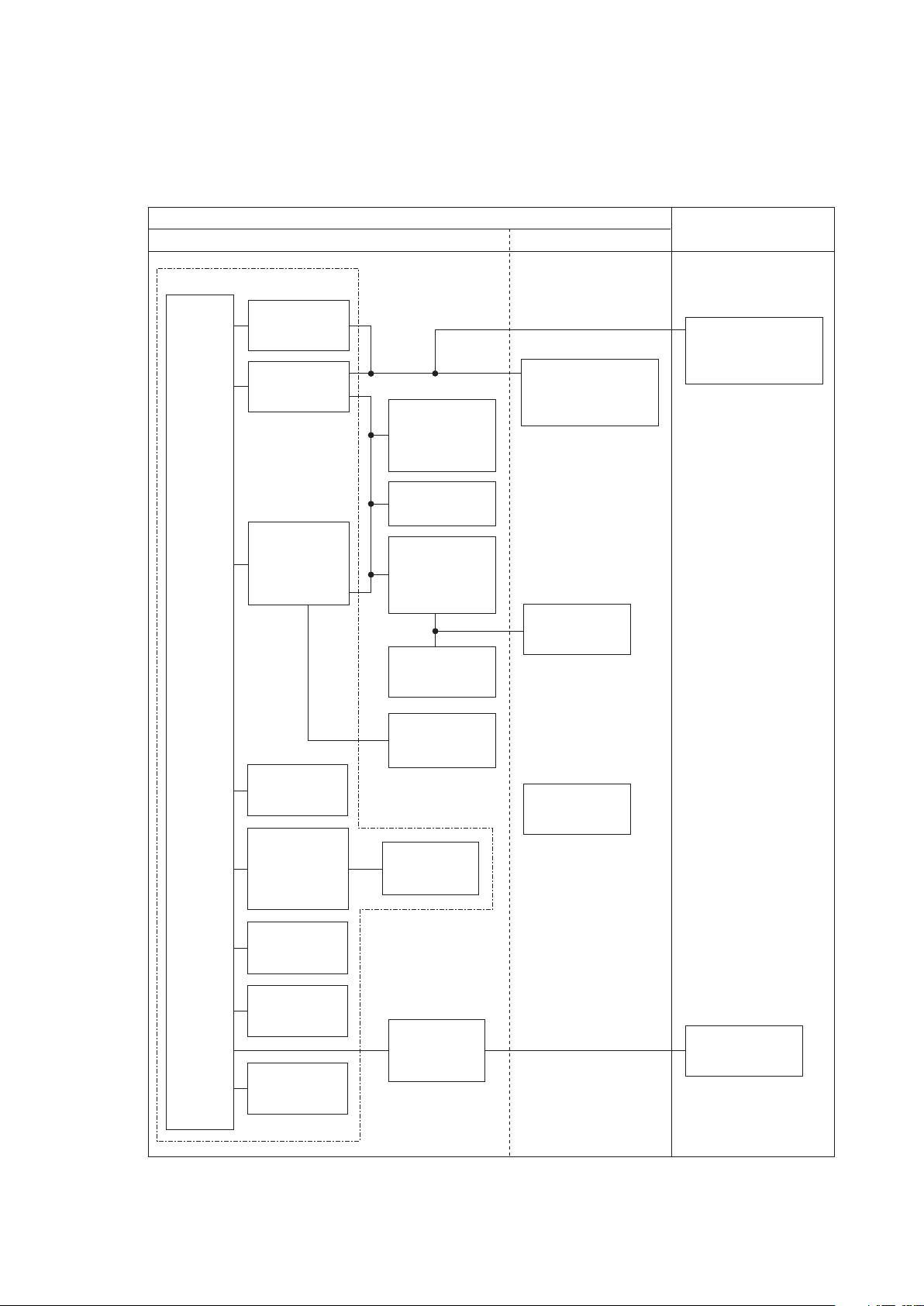
Input unit
AY-631P/633P
AY-651P/653P
AY-661P*/663P*
AY-671P/673P
Recorder
module
WS-671P
Transmitter
ZS-900P
Wireless LAN
station
QI-320PA
BSM-6301/6501/6701
Interface
QI-632P/634P
(For MU-631R)
QI-672P
(For MU-651R/671R)
Interface
QI-631P
(For MU-631R)
Interface
QI-671P
(For MU-651R/671R)
Main unit
MU-631R/
671R/651R
Input unit
AY-660P*
Multigas unit
GF-110PA/210R*
Multigas/Flow unit
GF-120PA*/220R*
Neuro unit
AE-918P*
* These units are not available for BSM-6000A series.
Environment for External Instruments
Use external instruments in the following environment.
When a JA-690PA/JA-694PA data acquisition unit is not connected to the
bedside monitor
Page 18

1. INSTALLATION/CONNECTION
Medically-used room
Patient Environment
Outside the Patient Environment
Non-medically used room
Interface
QI-671P
(For MU-651R/671R)
Interface unit
QI-600P
Interface
QI-632P/634P
(For MU-631R)
QI-672P
(For MU-651R/671R)
Recorder
module
WS-671P
BSM-6301/6501/6701
Transmitter
ZS-900P
Wireless LAN
station
QI-320PA
Sub display
(IEC 60601-1 complied or
using the isolation transformer
complied to IEC 60601-1)
Sub display
(IEC 60601-1 complied or
using the isolation transformer
complied to IEC 60601-1)
Remote controller
RY-910PA
Data acquisition
unit
JA-690PA/694PA
Central monitor
Network printer
(IEC xxx complied)
Hyper isolation
transformer
QW-100Y
(HIT-100)
Smart
expansion unit
AA-672P/674P
Input unit
AY-631P/633P
AY-651P/653P
AY-661P*/663P*
AY-671P/673P
Input unit
AY-660P*
External
instruments
(IEC 60601-1 complied)
External
instruments
(IEC 60601-1 complied)
External
instruments
(IEC 60601-1 complied)
External
instruments
(IEC 60601-1 complied)
Main unit
MU-631R/
671R/651R
Interface
QF series
Communication
cable
IF series
Neuro unit
AE-918P*
Interface
QF series
Communication
cable
IF series
Interface
QI-631P
(For MU-631R)
Mouse
Bar code reader
Multigas unit
GF-110PA/210R*
Multigas/Flow unit
GF-120PA*/220R*
* These units are not available for BSM-6000A series.
When a JA-690PA/JA-694PA data acquisition unit is connected to the
bedside monitor
1
Administrator’s Guide BSM-6000 1.7
Page 19

1.8 Administrator’s Guide BSM-6000
1. INSTALLATION/CONNECTION
To a wall outlet
To a wall ground
terminal
Display, PC
YS-096P2/096P3
Unit connection cable
Network
Connected to multi-link socket
* These units are not available for BSM-6000A series.
** These unit is not available for BSM-6000K series.
QF-901P/902P/903P/
904P/905P*/907P/908P/
909P/911P*/921P**
Interface
IF-913P/914P/917P*/
919P/920P*/922P/
923P/925P
Communication cable
GF-110PA/210R*
Multigas unit
GF-120PA*/220R*
Multigas/flow unit
AE-918P*
Neuro unit
Connected to USB socket
Mouse Bar Code Reader
AY-631P/651P/
661P*/671P
AY-633P/653P/
663P*/673P
Input unit
AY-660P*
Input unit
Hyper isolation
transformer
QW-100Y
(HIT-100)
QI-671P
Interface
(For MU-651R/671R)
WS-671P
Reccorder module
ZS-900P*
Transmitter
DH-600P
Handle
QI-320PA
Wireless LAN station
DI-590P*
Holder
QI-631P
Interface
(For MU-631R)
QI-600P
Interface unit
QI-672P
Interface
(For MU-651R/671R)
QI-632P/634P
Interface
(For MU-631R)
JA-690PA
Data acquisition unit
JA-694PA
YS-096P5
Multi-link cable
Bedside monitor
MU-671R MU-651R MU-631R
AA-672P AA-674P
Smart expansion unit
QI-672P QI-632PQI-634P
Connection Overview
Page 20
1. INSTALLATION/CONNECTION
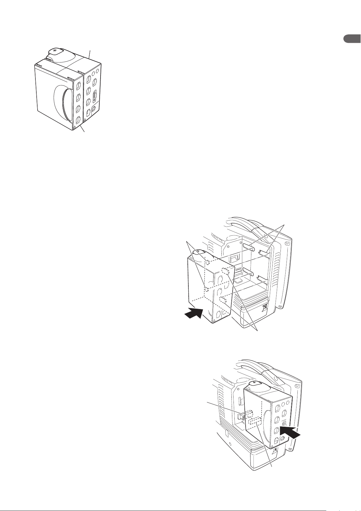
Slots
Tabs
Tabs
Connector on
the monitor
Connector on
the input unit
Input unit
Smart expansion unit
Input unit
Smart expansion unit
Attaching the AA-672P or AA-674P Smart Expansion Unit to the AY series Input Unit
Attach the smart expansion unit to the input unit before
mounting the input unit onto the monitor. Only one smart
expansion unit can be attached to the input unit. For details
on how to attach the smart expansion unit, refer to the
manual provided with the unit.
NOTE
The AA-672P or AA-674P smart expansion unit does
not function when it is attached to the AY-660P input
unit.
Mounting the AY series Input Unit onto the Monitor
1. Mount the input unit onto the rear of the monitor so that the tabs on the input
unit go into the slots on the monitor.
1
2. Slide the input unit in the direction of the arrow until it clicks into place.
Administrator’s Guide BSM-6000 1.9
Page 21

1.10 Administrator’s Guide BSM-6000
1. INSTALLATION/CONNECTION
Using an Optional Handle
A DH-600P handle can be attached to the input unit so that the input unit can be
removed from the main unit and carried around easily. For details on the handle,
refer to the manual provided with the handle.
Attaching the ZS-900P Transmitter
The ZS-900P transmitter transmits data from the monitor to a cardiac telemetry
system or central monitor. A multiple patient receiver is necessary with the
central monitors.
Handle
To connect the transmitter to the monitor, the optional DI-590P holder is
required. Connect the transmitter to the monitor by referring to the DI-590P
holder installation guide.
When the transmitter is connected to the monitor, turn the monitor power on and
check that the LED on the transmitter lights in green. Also check that the channel
number displayed in the upper part of the screen is correct.
ZS-900P transmitter and
ZS-900P transmitter and
DI-590P holder are not
DI-590P holder are not
available for BSM-6000A
available for BSM-6000A
series.
series.
CAUTION
When using a ZS-900P transmitter, the
measurement values and displayed waveform on
the bedside monitor and receiving monitor may
differ due to timing delay of the display and other
factors. Be careful when reading the value and
waveform.
Channel number
CAUTION
When the ZS-900P transmitter is attached to the
bedside monitor, check the alarm, arrhythmia
and monitoring settings on the central monitor
or telemetry system. The transmitter does not
transmit the alarm, arrhythmia and monitoring
setting information.
Page 22
1. INSTALLATION/CONNECTION
CAUTION
The ZS-900P transmitter can only transmit
temperature data from 5 to 45°C (41 to 113°F).
Be careful when reading the value.
• Before connecting the transmitter, turn off the monitor power.
• The ZS-900P transmitter does not comply with the CE mark.
• A ZB-800P or ZB-900P transmitter cannot be used on this monitor.
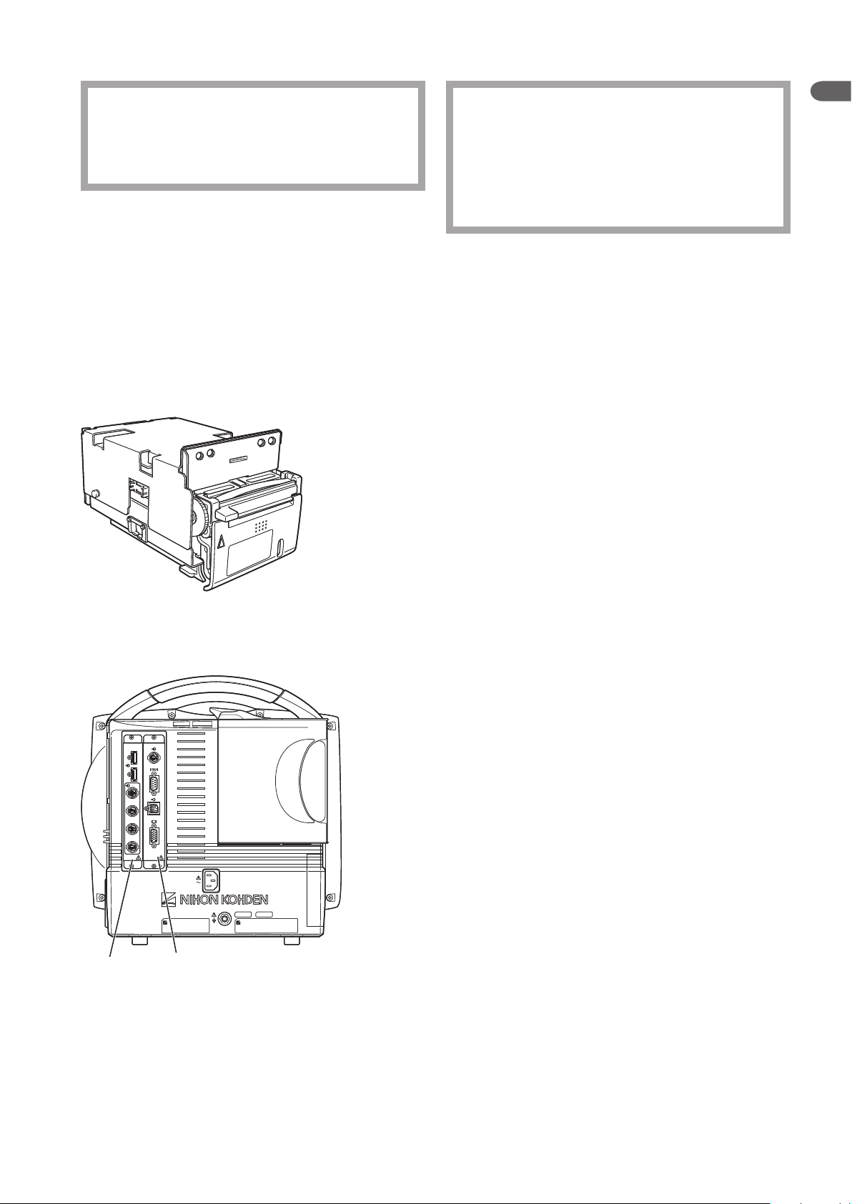
Installing the WS-671P Recorder Module
Install the optional WS-671P recorder module in the monitor by referring to the
WS-671P recorder module installation guide. To load the recording paper, refer
to Operator’s Manual or Section 2 of the User’s Guide Part I.
CAUTION
1
The ZS-900P transmitter can only transmit CO2
data from 0 to 100 mmHg (0 to 13.3 kPa). When
the transmitting data is out of this range, the
receiving monitor displays it as 100 mmHg. Be
careful when reading the value.
NOTE
Installing the QI-631P, QI-632P, QI-634P, QI-671P or QI-672P Interface
When the interface is installed in the monitor, external instruments can be
connected to the monitor.
The illustration on the left shows both the QI-671P and QI-672P
interfaces are installed in the BSM-6701 bedside monitor.
The interface has 2, 3, 4 or 6 sockets.
For BSM-6301:
• QI-631P: RS-232C, RGB
• QI-632P: USB, multi-link, alarm signal output
• QI-634P: USB, multi-link
For BSM-6501 and BSM-6701:
• QI-671P: Multi-link, RS-232C, alarm signal output, RGB
• QI-672P: 2 USB, 4 multi-link
QI-671PQI-672P QI-671PQI-672P
Install the optional interface in the monitor by referring to the manual
provided with the interface.
Administrator’s Guide BSM-6000 1.11
Page 23
1.12 Administrator’s Guide BSM-6000
1. INSTALLATION/CONNECTION
Mouse
QI-672P interface
Mouse
QI-672P interface
QI-672P interface
Bar code reader
QI-672P interface
Bar code reader
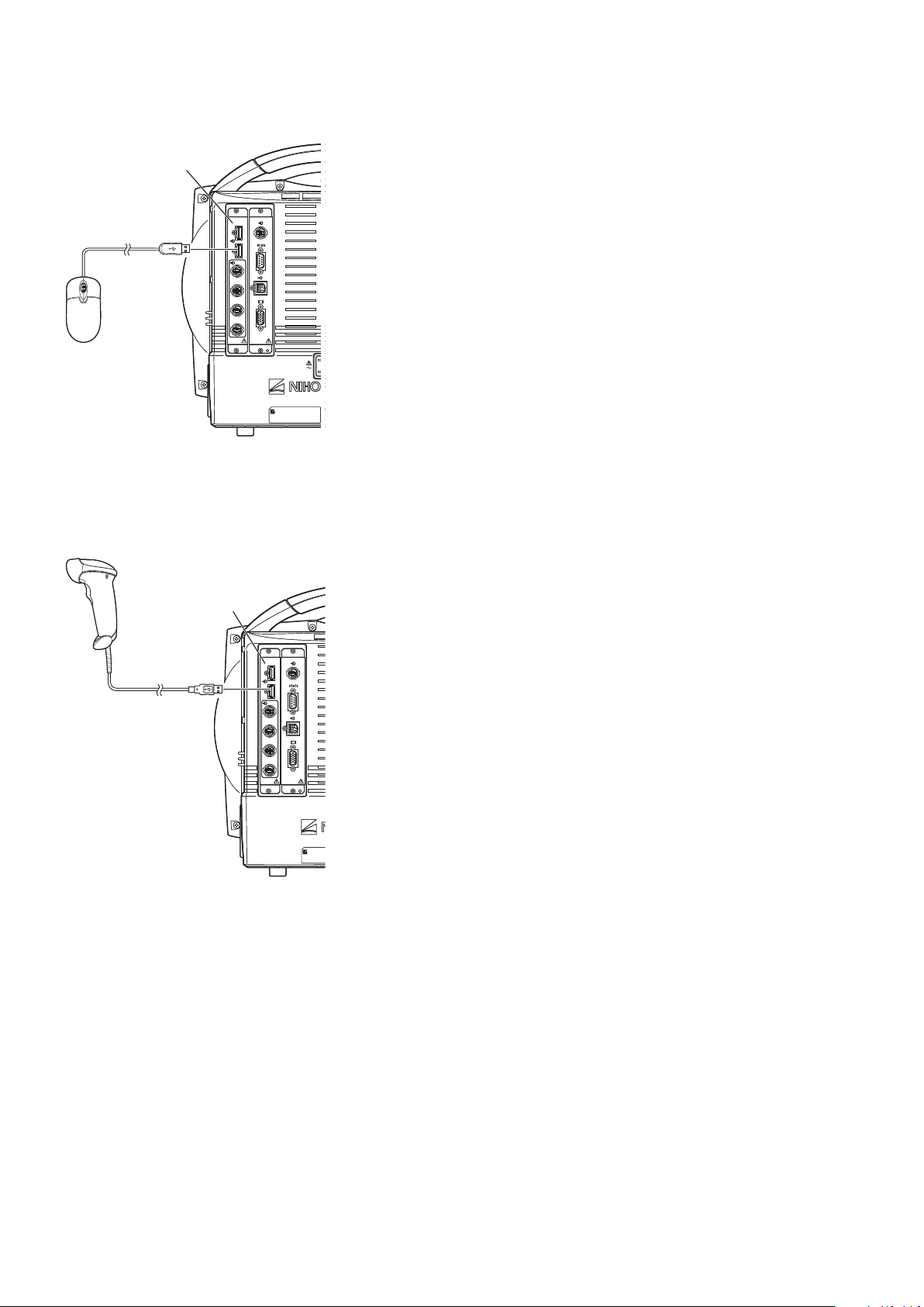
Connecting the Mouse
To connect the mouse, the QI-632P, QI-634P or QI-672P interface is required.
The QI-632P and QI-634P interfaces are for BSM-6301. The QI-672P interface
is for BSM-6501 and BSM-6701.
The illustration on the left shows both the QI-672P and QI-671P interfaces are
installed in the BSM-6701 bedside monitor.
Connect the mouse cable to the USB socket on the interface which is installed in
the monitor.
Connecting the Bar Code Reader
To connect the bar code reader, the QI-632P, QI-634P or QI-672P interface is
required. The QI-632P and QI-634P interfaces are for BSM-6301. The QI-672P
interface is for BSM-6501 and BSM-6701.
The illustration on the left shows both the QI-672P and QI-671P interfaces
installed in the BSM-6701 bedside monitor.
Connect the bar code reader cable to the USB socket on the interface which is
installed in the monitor.
Refer to the “Setting the Bar Code Reader” later in this section for setting the bar
code reader.
Page 24
1. INSTALLATION/CONNECTION
Connecting the JA-690PA or JA-694PA Data Acquisition Unit
To connect the JA-690PA or JA-694PA data acquisition unit, the YS-096P2 or
YS-096P3 unit connection cable is required. Connect the cable to the bedside
monitor and to the unit connection socket on the data acquisition unit.
For details on how to use the data acquisition unit, refer to the data acquisition
unit operator’s manual.
NOTE
• Connect the unit connection cable to the unit connection socket on the
data acquisition unit straight until it locks firmly.
• Keep the cable out of the way by running it along the floor or wall.
Otherwise people may trip over it, causing the instrument to fall and
injure the patient and operator.
1
YS-096P2/YS-096P3 unit
connection cable
Administrator’s Guide BSM-6000 1.13
Page 25

1.14 Administrator’s Guide BSM-6000
1. INSTALLATION/CONNECTION
Connecting External Instruments
To connect the external instruments, the QI-632P or QI-634P interface for BSM-
6301 or QI-671P or QI-672P interface for BSM-6501 and BSM-6701 must be
installed in the monitor.
Connecting a GF-110PA or GF-210R Multigas Unit, GF-120PA or GF-
220R Multigas/Flow Unit or AE-918P Neuro Unit
GF-210R multigas unit, GF-120PA or GF-220R multigas/flow unit and AE-
918P neuro unit are not available for the BSM-6000A series.
Connect the GF-110PA or GF-210R multigas unit, GF-120PA or GF-220R
multigas/owunitorAE-918Pneurounittooneofthemulti-linksocketsonthe
QI-632P, QI-634P, QI-671P or QI-672P interface.
When a multigas unit or multigas/flow unit is connected to the monitor
and the monitor is in operation, do not connect any other instrument to
the monitor with a multi-link cable. If another multi-link cable is connected
to the main unit during operation, the multigas unit or multigas/flow
unit may enter warmup status and automatically restart monitoring 45
seconds (AG-920R, GF-110PA, GF-120PA) or 6 minutes (GF-210R, GF-
220R) after warmup.
NOTE
NOTE
The following example shows both the QI-671P and QI-672P interfaces
installedintheBSM-6701bedsidemonitorandaGF-120PAmultigas/owunit
connected.
Connecting Example
QI-671P interface
QI-672P interface
GF-120PA multigas/flow unit
Page 26

1. INSTALLATION/CONNECTION
QF series interface or
IF series communication cable
To external devices
QI-671P interface
QI-672P interface
Connecting an External Instrument Using a QF Series Interface or IF
Series Communication Cable
Connect the QF series interface cable or IF series communication cable to the
external instrument and to one of the multi-link sockets on the QI-632P, QI-634P,
QI-671P or QI-672P interface.
The following example shows both the QI-671P and QI-672P interfaces installed
in the BSM-6701 bedside monitor.
NOTE
Do not connect or remove the QF series interface or IF series
communication cable connector while the monitor power is on. The
monitor might not function properly.
1
Connecting a Sub Display
A sub display can be connected to the bedside monitor. Connect the sub display
to the RGB socket on the QI-631P interface for a BSM-6301 bedside monitor
or to the QI-671P interface for a BSM-6501 or BSM-6701 bedside monitor. The
subdisplaymustmeetthefollowingspecications.AnNECLCD191VXMor
equivalent display is recommended.
MinimumspecicationsforBSM-6701display:
• Resolution: 1024 × 768
• InputAnalogRGB:0.7Vp-p
• V-sync:60.0Hz
• H-sync: 48.4 kHz
MinimumspecicationsforBSM-6301andBSM-6501display:
• Resolution: 800 × 600
• InputAnalogRGB:0.7Vp-p
• V-sync:60.3Hz
• H-sync: 37.9 kHz
Administrator’s Guide BSM-6000 1.15
Page 27

1.16 Administrator’s Guide BSM-6000
1. INSTALLATION/CONNECTION
To connect the display to the interface, use the YS-080P3 RGB cable (10 m). The
sub display must be connected to the SM-800R isolation transformer.
The screen to be displayed on the sub display can be set to either of the following
on the DISPLAY page of the SYSTEM SETUP window. Refer to Section 3.
• SLAVE: Samescreenasthebedsidemonitor.
• HOME SCREEN: The home screen is always displayed.
Page 28
1. INSTALLATION/CONNECTION
Connecting the Power Cord and Grounding Lead
General
The monitor can operate on either battery or AC power.
When the power cord is plugged into an AC outlet and the power switch on the
front panel is turned on, the monitor operates on AC power.
When a battery pack is inserted and the power cord is disconnected or there is a
sudden power failure, the monitor automatically switches to battery power.
The battery pack is charged when the power cord is plugged into an AC outlet
and the AC current is supplied to the monitor. The battery pack is also charged
during monitoring.
The monitor can operate for about 60 minutes on the BSM-6301 and BSM-6501
or about 45 minutes on the BSM-6701 with a new fully charged battery pack
when:
• Used in normal temperature.
• Recorder is stopped.
• No alarm occurs.
• Monitoring ECG, respiration (impedance) and SpO2.
• <POWERSAVINGMODE>ontheSYSTEMSETUPwindowissettoON.
• <SYNCSOUNDVOLUME>ontheVOLUMEwindowissettoOFF.
• NIBP measurement interval is 15 minutes.
• QI-671P and QI-672P interfaces or QI-631P and QI-632P or QI-634P
interfaces are installed in the monitor.
1
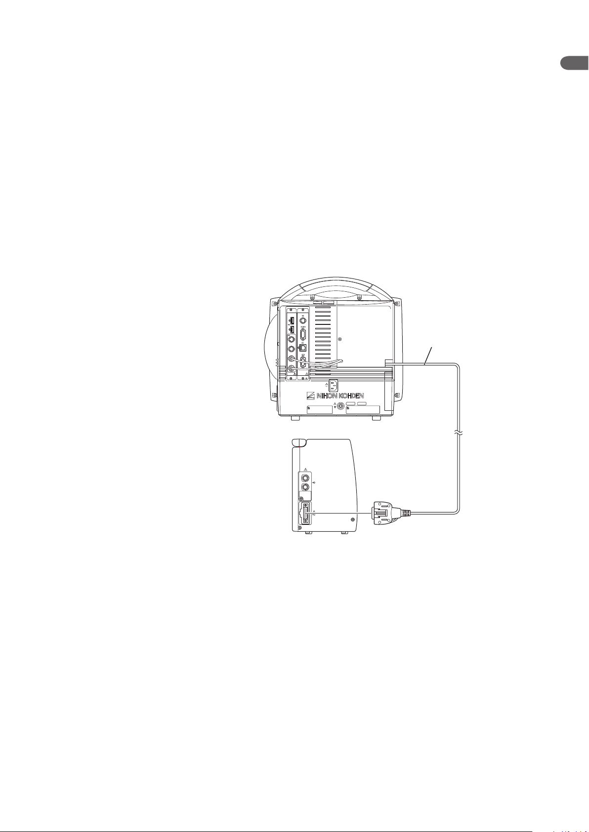
Connecting the Power Cord
WARNING
Only use the provided power cord. Using other power cords may
result in electrical shock or injury to the patient and operator.
Connect the provided power cord to the AC SOURCE socket on the rear panel of
the monitor and plug the cord into a 3-prong AC outlet.
When AC power is supplied to the monitor, the AC power lamp on the front
panel lights.
NOTE
If the AC power lamp does not light, check the power cord connection.
Administrator’s Guide BSM-6000 1.17
Page 29
1.18 Administrator’s Guide BSM-6000
1. INSTALLATION/CONNECTION
AC power lamp lights
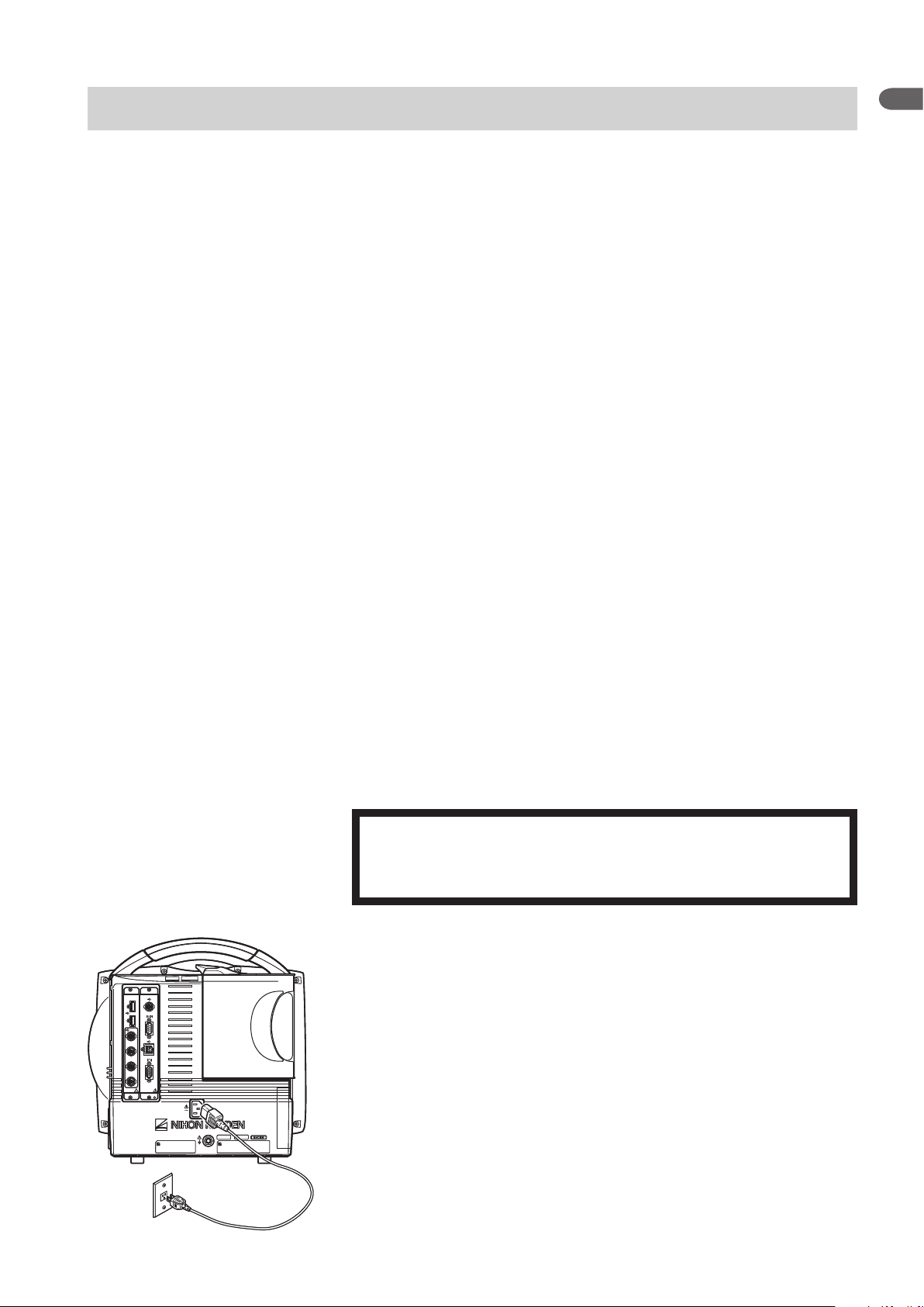
Grounding the Monitor
WARNING
When several medical instruments are used together, ground all
instruments to the same one-point ground. Any potential difference
between instruments may cause electrical shock to the patient and
operator.
When more than one electrical instrument is used, there may be electrical
potential difference between the instruments. The potential difference between
theinstrumentsmaycausecurrenttoowtothepatientconnectedtothe
instruments, resulting in electrical shock (micro shock).
Always perform equipotential grounding when required. It is often required in
the operating room, ICU room, CCU room, cardiac catheterization room and X-
ray room. Consult with a biomedical engineer to determine if it is required.
When equipotential grounding is required, connect the equipotential ground
terminal on the instrument to the equipotential ground terminal on the wall
(equipotential grounding system) with the equipotential grounding lead (potential
equalization conductor).
Page 30

1. INSTALLATION/CONNECTION
Connecting the Monitor to the Network
The network connection method differs according to the installation location of
the monitor and the network components. The network connection must comply
with IEC 60601-1-1 “General Requirements for Safety of Medical Electrical
Equipment”. For details, refer to the “Network and System Installation Guide”
which is available from your Nihon Kohden representative.
WARNING
Connect the monitor to network as specified.
Otherwise the patient and operator may receive
electrical shock or injury. To connect the network,
contact your Nihon Kohden representative.
WARNING
Install all network devices, including printer
and hubs, outside the patient environment (IEC
60601-1-1). If they are installed inside the patient
environment, the patient or operator may receive
electrical shock or injury. For installation, contact
your Nihon Kohden representative.
In a network where this monitor is connected,
connect only the specified instruments.
Unspecified instruments may cause electrical
shock or injury to the patient and operator or
cause instrument malfunction, instrument stop, or
data loss.
Check the software version number of the
monitor before connecting it to the network.
Different software versions have different
communication methods. More than one
communication method in a network may cause
communication failure. For details, refer to the
Network and System Installation Guide.
1
WARNING
WARNING
Administrator’s Guide BSM-6000 1.19
Page 31

1.20 Administrator’s Guide BSM-6000
1. INSTALLATION/CONNECTION
LAN cable
LAN cable
To network
QW-100Y(HIT-100)
Hyper isolation
transformer
Connecting the QW-100Y (HIT-100) Hyper Isolation Transformer
ConnectthemonitortothenetworkwiththespeciedLANcable.Connect
the QW-100Y (HIT-100) hyper isolation transformer between the monitor and
network.
WARNING
Do not use a damaged network cable. The patient or operator may
receive electrical shock when the damaged part is touched.
NOTE
The time on this monitor is automatically adjusted to match the time of
the network as long as the monitor is connected to the network. The date
and time on all monitors in the network are set to the same setting.
Connecting the QI-320PA Wireless LAN Station
Connect the QI-320PA wireless LAN station to the bedside monitor with a
speciedwirelessLANaccesspoint.RefertotheQI-320PAwirelessLAN
station operator’s manual.
QI-320PA
Wireless LAN station
Page 32

1. INSTALLATION/CONNECTION
Power lamp lights
Turning the Power On/Off
Check Before Turning On the Power
Check the following items before turning on the power.
• Enough electrodes and electrode leads are ready.
• Cleaned and sterilized sensors and transducers are ready.
• Power cord is connected properly.
• Equipotential grounding lead is connected properly when equipotential
grounding is required.
• All cables are connected properly.
• Enough recording paper in the recorder (when using an optional recorder).
• Fully charged battery pack is installed in the monitor in case of a sudden power
failure.
• No scratches, damage or dirt on the monitor.
• No damage to the keys and panels.
• No damage to the power cord.
• No damage to the electrode leads, transducers, probes and cables.
• The monitor is not in a wet place.
1
Turning the Power On
CAUTION
Do not turn the monitor off when the system check screen is
displayed. Otherwise the saved data may be damaged or deleted.
If the monitor is turned off during system check, delete all data
because the data is not reliable.
NOTE
• It takes a few minutes for the LCD screen to reach full brightness.
• The shadow of the previous screen may remain for a few minutes after
changing screens.
• There may be some dots on the LCD screen which are always on or
always off, but it does not affect monitoring. This is normal for all LCD
screens.
• Even though the position of symbol marks for the lamps are different on
BSM-6301 and BSM-6501 or BSM-6701, the function and the position
of lamps are the same.
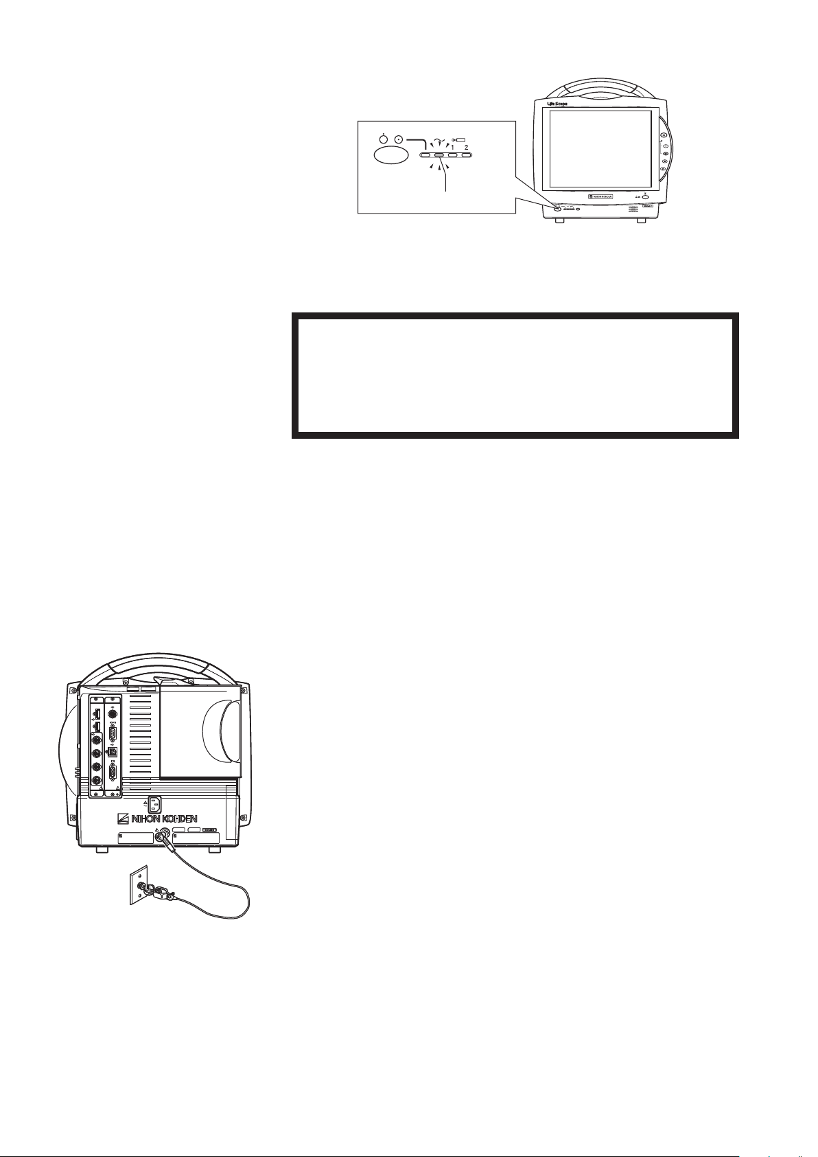
Press the [power] switch on the front panel to turn the power on. The power lamp
and the AC power lamp light and self check starts. When the check is complete,
the home screen appears.
Administrator’s Guide BSM-6000 1.21
Page 33

1.22 Administrator’s Guide BSM-6000
1. INSTALLATION/CONNECTION
If the power lamp does not light, check the power cord connection.
CAUTION
When the monitor is turned on, check that a single beep sounds and
the red, yellow, cyan and green alarm indicator lamps blink once.
This shows that the alarm is functioning properly.
When the monitor power is turned on, alarms are suspended while the monitor is
waiting for the electrodes and probe to be attached to the patient. The monitoring
starts when the connection cord is connected to the socket on the monitor and the
electrodes or probe are attached to the patient. The alarm activates when one of
the following occurs:
• at least one parameter is measured and a value is displayed (when AUTO is
selectedfor<ALARMACTIVATIONDELAY>ontheALARMwindowof
the SYSTEM SETUP window)
• ECG, SpO2 or IBP is continuously monitored for the selected time (when 1
min,2minor3minisselectedfor<ALARMACTIVATIONDELAY>)
• NIBP is measured (when 1 min, 2 min or 3 min is selected for <ALARM
ACTIVATIONDELAY>)
When <AUTO ADMIT> in the SYSTEM CONFIGURATION screen is set
to ON and the monitor power is turned on for more than 30 minutes after the
turning power off, the stored data in the monitor is deleted. When the monitor
is turned on in less than 30 minutes after turning power off, the stored data is
not deleted and monitoring continues. When <AUTO ADMIT> in the SYSTEM
CONFIGURATION screen is set to OFF, the message appears asking whether
monitoring a new patient or not. The factory default setting is ON.
Check After Turning On the Power and During Monitoring
To start monitoring safely and properly, check the following items after turning
on the power. If any problem is detected, take the proper countermeasure
according to the troubleshooting and maintenance sections.
• Thereisnore,smokeorsmell.
• The monitor is not too hot.
• The power lamp and other lamps light.
• The red, yellow, cyan and green alarm indicator lamps blink once and a beep
sounds.
• The start up screen appears and the home screen appears.
• No error message is displayed on the screen.
• The time on the screen is correct.
• The monitor does not affect surrounding equipment.
• The data and waveforms are displayed properly.
• Keys and switches operate properly.
• The touch keys function properly and the key clicking sound is generated.
• Alarm functions properly.
• Alarm sound can be heard.
Page 34

1. INSTALLATION/CONNECTION
• Alarm sound volume setting is appropriate.
• There is no trouble in recording (when using an optional recorder).
After turning the monitor on and when admitting a patient on the monitor,
make sure that the time displayed at the upper right of the screen is
correct. When the date or time is changed during monitoring, the date and
time of all stored data is also changed and might not match the date and
time on the printout.
When the monitor is connected to a network
The time on this monitor is automatically adjusted to match the time of
the network as long as the monitor is connected to the network. The date
and time on all monitors in the network are set to the same setting.
Monitor Status on Power Interruption
When there is a power failure or sudden power interruption, the monitor status is
as follows.
• When a battery pack is installed in the monitor, the BSM-6301 and BSM-6501
operate for about 90 minutes and the BSM-6701 operates for about 60 minutes
on battery power.
• When the monitor has no battery pack installed or the battery pack is
discharged, the monitor turns off. When <AUTO ADMIT> in the SYSTEM
CONFIGURATION screen is set to ON, the patient data and settings return to
the default settings 30 minutes after the monitor is turned off. When <AUTO
ADMIT> is set to OFF, you can select whether to save the settings or initialize
the master settings. If the monitor power is turned off and on again within 30
seconds, monitoring continues.
1
NOTE
Turning the Power Off
When there is a power failure or sudden power interruption, immediately connect
the monitor to the emergency power source. It is recommended to always keep
the battery pack in the monitor.
NOTE
Even though the position of symbol marks for the lamps are different on
BSM-6301 and BSM-6501 or BSM-6701, the function and the position of
lamps are the same.
Press the [power] switch on the front panel for more than 3 seconds to turn the
power off. The screen becomes dark and the power lamp on the front panel turns
off.
Administrator’s Guide BSM-6000 1.23
Page 35

1.24 Administrator’s Guide BSM-6000
1. INSTALLATION/CONNECTION
Check After and Before Turning the Power Off
Check the following items for the next use.
• Previous patient data is deleted.
• Temporarily changed settings are changed back to the previous settings.
• There is no dirt, damage or scratches on the monitor.
• The sensors, probes, transducers, and cables are cleaned and sterilized.
• Accessories are cleaned and stored properly.
• There are enough consumables, such as recording paper, and disposable
electrodes for the next use.
• Battery pack is fully charged.
• The [power] switch on the monitor is turned off and the power cord is
disconnected from the monitor.
• The monitor is not in a wet place.
• Dead batteries are disposed of properly.
• Medical waste is disposed of properly.
• The monitor is stored properly.
Page 36

1. INSTALLATION/CONNECTION
Setting the Bar Code Reader
Scanning the Bar Code Reader Settings
You can use the Symbol LS2208 from Motorola, Inc. Refer to the manual. You
can download the manual from http://support.symbol.com on the Motorola
website.
Following are the minimum settings of the bar code reader. Scan the following
bar codes in order. When scanning the bar code, there is one short high beep. For
further settings, refer to the Symbol LS2208 manual.
*: This setting is a default value. You can skip scanning this bar code if you have
already used this bar code reader with the default value.
Beeper Volume
LowVolume
1
USB Device Type
HID Keyboard Emulation*
USB Country Keyboard Types (Country Codes)
North American Standard USB Keyboard*
Transmit Code ID Character
None*
Scan Data Transmission Format
Scan Options
<DATA> <SUFFIX>
Administrator’s Guide BSM-6000 1.25
Page 37

1.26 Administrator’s Guide BSM-6000
1. INSTALLATION/CONNECTION
Enter
Transmit “No Read” Message
Disable No Read*
Enable/Disable Codabar
Enable Codabar
Initializing the Bar Code Reader
Scanning this bar code returns all data to the default values. Scan the following
bar code if you want to initialize the bar code reader.
Set All Defaults
Checking the Bar Code Reader Operation
Scan the bar code of the patient on the home screen (for BSM-6000A series only)
or the PATIENT ID window of the PATIENT INFO page in the ADMIT window
and check the patient ID is entered on the PATIENT ID window of the PATIENT
INFO page in the ADMIT window.
Page 38

1. INSTALLATION/CONNECTION
Calibrating the Touch Screen
Calibrate the touch screen when the pressed position and the activated position
do not match.
1. Turn the monitor power off.
2. Press the [power] switch while pressing the [Silence Alarms] key on the
front panel until the DIAGNOSTIC CHECK screen is displayed.
3. Press the [Menu] key. The TOUCHPANEL CALIBRATION screen appears.
1
4. Touch the @ mark at the upper left corner of the screen for 2 seconds. When
the mark is correctly touched, another mark appears in the lower right corner
of the screen. Touch the mark for 2 seconds.
When the marks are touched correctly, the “TOUCHPANEL
CALIBRATION SUCCEEDED” message appears, then the DIAGNOSTIC
CHECK screen appears.
5. Touch the RETURN key to display the home screen.
Administrator’s Guide BSM-6000 1.27
Page 39

1.28 Administrator’s Guide BSM-6000
1. INSTALLATION/CONNECTION
Using ECG/BP Output as the Synchronous Signal
The ECG, IBP and heart rate pulse trigger output signal from the monitor can
be used as the synchronizing signal on a medical electrical instrument, such as
IABPequipmentordebrillator,whichcomplieswithIEC60601-1.
CAUTION
When using the output signal from the monitor
as the synchronization signal for other equipment
such as an IABP (intra-aortic balloon pump) or
defibrillator:
• Set the timing of the IABP by checking the
waveform on the IABP screen.
• Check the condition of the bedside monitor
at all times. The output signal may become
unstable.
• Check that the delay time of the output signal is
within the range of the connected equipment.
• When using an IBP waveform as a synchronization signal for other
equipment, connect the IBP line to the MULTI socket on the input unit.
The IBP waveform that is used for the synchronization signal depends
on the “IBP ANALOG OUT” setting in the SYSTEM SETUP window.
- When “IBP ANALOG OUT” is set to “FIXED POSITION”:
The IBP line connected to the top MULTI socket on the input unit is
used.
- When “IBP ANALOG OUT” is set to “HIGHEST PRIORITY LABEL” :
When more than one IBP waveform is acquired, the IBP waveform of
the highest priority label is used.
IBP label priority:
ART > ART2 > RAD > DORS > AO > FEM > UA > LVP > P1 > P2 >
P3 > P4 > P5 > P6 > P7
• The output signal from the ECG/BP OUT socket may become unstable
in the following conditions.
- Electrode is dry or detached.
- Electrode lead is damaged or disconnected from the electrode.
- Electrode lead is pulled.
- AC interference or EMG noise superimposed.
- Air bubbles or blood clog in the circuit for monitoring IBP.
- Cord or cable is disconnected or damaged.
• All instruments which are to be connected to the ECG/BP OUTPUT
socket must use a YJ-910P or YJ-920P ECG/BP output cable and
comply with the IEC 60601-1 safety standard for medical equipment.
• When using an IABP, set <CALCULATION METHOD> on the OTHER
ECG/BP OUT socket
ECG/BP OUT socket
Outputs1V/1mVECG,1V/100
Outputs1V/1mVECG,1V/100
mmHg BP and open collector
mmHg BP and open collector
heart rate trigger signals
heart rate trigger signals
page of the PRESS window to “PEAK” to improve measurement
accuracy.
• The AY-660P input unit has no ECG/BP OUT socket and no signal can
be output.
CAUTION
Only a Nihon Kohden defibrillator can use
the output signal from the monitor as a
synchronization signal. Check that the delay time
of the output signal (heart rate trigger 20 ms
maximum) is within the range of the connected
defibrillator.
NOTE
Page 40

1. INSTALLATION/CONNECTION
Connect the YJ-910P or YJ-920P ECG/BP output cable to the ECG/BP OUT
socket on the input unit and the external instrument.
The following shows the delay time of the output signal.
Output Signal Delay Time
ECG 20 ms
BP 40 ms
Heart rate trigger 20 ms
1
Administrator’s Guide BSM-6000 1.29
Page 41

Section 2 Changing SYSTEM
CONFIGURATION Screen
Settings
Overview ..............................................................................................................................................................2.2
Setting Items on the SYSTEM CONFIGURATION Screen ....................................................................... 2.2
Displaying the SYSTEM CONFIGURATION Screen ................................................................................. 2.3
Closing the SYSTEM CONFIGURATION Screen ..................................................................................... 2.5
SITE Window ....................................................................................................................................................... 2.6
NETWORK Window .............................................................................................................................................2.7
UNITS Window .................................................................................................................................................... 2.8
TRANSPORT Window ......................................................................................................................................... 2.9
PC Window ........................................................................................................................................................ 2.11
CHANGE PASSWORD Window ........................................................................................................................ 2.12
OTHER Window ................................................................................................................................................2.13
Initializing the Monitor ........................................................................................................................................ 2.14
2
Administrator’s Guide BSM-6000 2.1
Page 42

2.2 Administrator’s Guide BSM-6000
2. CHANGING SYSTEM CONFIGURATION SCREEN SETTINGS
Overview
The section explains how to change settings on the SYSTEM
CONFIGURATION screen.
The initial settings on the SYSTE M CONFIGURATION screen must be
changed before monitoring. Changing these settings during monitoring interrupts
monitoring. All other settings can be changed any time without interrupting
monitoring. You can check the contents of the SYSTEM CONFIGURATION
screen settings on the CONFIGURATION page of the SYSTEM SETUP window
so that the monitor power does not need to be turned off and monitoring is not
interrupted (refer to Section 3).
This section also explains how to initialize the monitor. This procedure returns
all settings to the factory default settings and deletes all stored data in memory.
Setting Items on the SYSTEM CONFIGURATION Screen
SITE window NETWORK window
UNITS window TRANSPORT window
Page 43

2. CHANGING SYSTEM CONFIGURATION SCREEN SETTINGS
PC window CHANGE PASSWORD window
OTHER window
2
Displaying the SYSTEM CONFIGURATION Screen
This procedure interrupts all monitoring. Only change these settings
before or after monitoring.
1. Turn the monitor power off.
2. Press the [power] switch while pressing the [Silence Alarms] key on the
front panel until the DIAGNOSTIC CHECK screen is displayed.
3. Touch the SYSTEM CONFIG key. The dialog box to enter the password
appears.
CAUTION
Administrator’s Guide BSM-6000 2.3
Page 44

2.4 Administrator’s Guide BSM-6000
2. CHANGING SYSTEM CONFIGURATION SCREEN SETTINGS
4. Enter the password with the number keys and touch the ENT key. The
SYSTEM CONFIGURATION screen appears.
The default password is “1234”.
5. Touch the desired tab to display the desired window.
6. Change any necessary settings.
Page 45

2. CHANGING SYSTEM CONFIGURATION SCREEN SETTINGS
Closing the SYSTEM CONFIGURATION Screen
1. Touch the close button ( ) on the SYSTEM CONFIGURATION screen to
return to the DIAGNOSTIC CHECK screen.
2. Touch the RETURN key. The home screen appears.
2
Administrator’s Guide BSM-6000 2.5
Page 46

2.6 Administrator’s Guide BSM-6000
2. CHANGING SYSTEM CONFIGURATION SCREEN SETTINGS
SITE Window
Select the site according to the operating environment. The default settings,
including alarm upper and lower limit settings, differ according to site.
OR: Sleep mode is not available. SIM mode for NIBP is available.
ICU: Sleep mode is available. SIM mode for NIBP is not available.
NICU: Sleep mode is available. SIM mode for NIBP and 12 lead analysis
is not available.
To change the site, select the new site. The “SITE SETTING WILL BE
CHANGED. OK?” message appears. Touch the YES key to change the site.
When the site is changed, the settings change to the factory default settings
according to the new site. The factory default settings of the SYSTEM
CONFIGURATION screen and SYSTEM SETUP window are listed in the
“Factory Default Settings” in Section 4 of this manual. Other default settings are
listed in the Operator’s Manual.
Page 47

NETWORK Window
2. CHANGING SYSTEM CONFIGURATION SCREEN SETTINGS
2
Set the network settings when the bedside monitor is connected to a central
monitor network.
CAUTION
The network must be managed by the network
administrator. Make sure that each monitor in the
network has a different IP address. Otherwise,
data communication cannot be performed
properly. When adding a monitor to an already
operating network, set the IP address on the
monitor before connecting the monitor to the
network.
CAUTION
When the monitor is connected to a central
monitor network, set the Bed Name (Bed ID)
and Group Name on the monitor. Otherwise,
the default settings are used for the bed name
and group name and the bed may be incorrectly
identified on the central monitor.
GROUP
Assign a group name for the bedside monitor. When the monitor has acquired the
information of the network to which it is connected, the group names assigned by
the central monitor appear. Select the group name from this list for the bedside
monitor. For details, refer to the central monitor operator’s manual.
IP ADDRESS SETUP: AUTO, MANUAL
When set to AUTO, the IP address and subnet mask are set automatically.
When set to MANUAL, touch the EDIT key to set the IP address, subnet mask
and default gateway.
Administrator’s Guide BSM-6000 2.7
Page 48
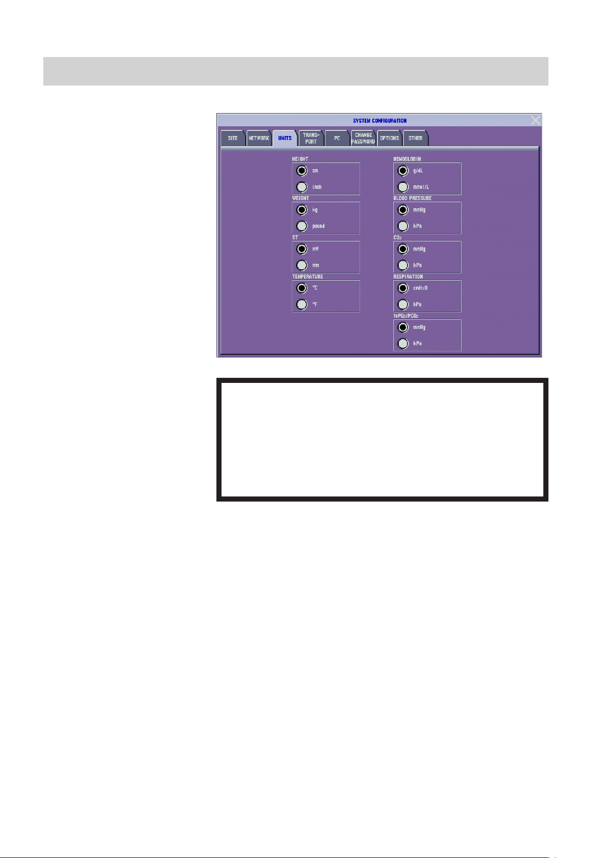
2.8 Administrator’s Guide BSM-6000
2. CHANGING SYSTEM CONFIGURATION SCREEN SETTINGS
UNITS Window
Select the unit for each parameter.
WARNING
ST, CO2, RESPIRATION, tcPO2/tcPCO2 and HEMOGLOBIN settings
only affect the individual bedside monitor, not on all monitors
connected to the network. The unit settings must be the same on all
bedside monitors and central monitors in the network. Otherwise,
the different measurement values and alarms will be displayed on
different monitors depending on the unit settings on each monitor.
NOTE
The CO2 and respiration unit settings are not available on the BSM-6000A
series.
Page 49

TRANSPORT Window
2. CHANGING SYSTEM CONFIGURATION SCREEN SETTINGS
2
DATA TRANSPORT USING INPUT UNIT: ENABLE, DISABLE
Select whether to enable the transport function. When the transport function is
enabled, the patient information and review data can be sent to another bed by
disconnecting the input unit from one monitor and connecting it into another
monitor.
NOTE
To use the transport function, set the <DATA TRANSPORT USING
INPUT UNIT> setting on the TRANSPORT window of the SYSTEM
CONFIGURATION screen on both the original monitor and the
destination monitor to ENABLE.
ENABLE: Enable the transport function of the monitor.
DISABLE: Disable the transport function of the monitor.
USE SETTINGS IN INPUT UNIT: On, Off
On: Patient information, pacing detection On/Off, QRS detection type,
arrhythmia analysis On/Off, vital sign upper/lower alarm limits settings,
arrhythmia alarms settings, arrhythmia recall settings, parameters to be
saved for full disclosure and ECG lead settings of TRACE 1 and TRACE 2
are sent to destination monitor.
Off: Patient information, pacing detection On/Off and QRS detection type are
sent to destination monitor.
Administrator’s Guide BSM-6000 2.9
Page 50

2.10 Administrator’s Guide BSM-6000
2. CHANGING SYSTEM CONFIGURATION SCREEN SETTINGS
TIME ZONE: 0 to ±12:00
When installing the monitor, change the time zone setting to the
same setting as the other bedside monitors and central monitors. If
the time zone setting is not the same, the data which was in the input
unit before transport is deleted when using the transport function
with the input unit.
Set the time zone in respect to GMT (Greenwich Mean Time). The time
difference can be selected in 30 minute steps.
This setting must be the same on all monitors in the same network. Otherwise
data communication problems may occur.
You can also change the time zone setting on the OTHER window of the
SYSTEM CONFIGURATION screen.
CAUTION
AUTO ADMIT: On, Off
On: When the monitor power is off for 30 minutes or more, the previous patient
and monitoring data is deleted. If the monitor power is off for less than
30 minutes, the patient and monitoring data is not deleted and monitoring
continues.
Off: The previous patient and monitoring data is not deleted when the monitor
is turned off. The “NEW PATIENT?” dialog box appears when the power
is turned on. When the “YES” key is touched, the previous patient and
monitoring data is deleted. When the “NO” key is touched, the patient and
monitoring data is not deleted and monitoring continues.
NOTE
When <DATA TRANSPORT USING INPUT UNIT> on the TRANSPORT
window of the SYSTEM CONFIGURATION screen is set to ENABLE,
AUTO ADMIT is fixed to OFF.
Page 51

PC Window
2. CHANGING SYSTEM CONFIGURATION SCREEN SETTINGS
Change settings according to the PC connected to the bedside monitor.
2
Administrator’s Guide BSM-6000 2.11
Page 52

2.12 Administrator’s Guide BSM-6000
2. CHANGING SYSTEM CONFIGURATION SCREEN SETTINGS
CHANGE PASSWORD Window
Set the 4-digit password required for displaying the SYSTEM SETUP window.
1. Enter the current password in the <OLD PASSWORD> box using the
number keys on the screen. The default password is “1234”.
2. Touch the ENT key. The “PLEASE ENTER NEW PASSWORD” message
appears.
3. Enter the new password in the <NEW PASSWORD> box using the number
keys on the screen.
4. Touch the ENT key to register the new password.
Page 53

OTHER Window
2. CHANGING SYSTEM CONFIGURATION SCREEN SETTINGS
2
ZS-900P TYPE: TYPE 8, TYPE A
Select the parameter group for transmitting data by the ZS-900P transmitter. CO2
data cannot be received by a monitor on which CO2 is not available.
TYPE 8: ECG, SpO2, NIBP, IBP connected to MULTI socket 1 or 2,
temperature connected to the TEMP sockets and respiration
(thermistor) connected to MULTI socket 1 or 2
TYPE A: ECG, SpO2, NIBP, IBP connected to MULTI socket 1 or 2,
temperature connected to the TEMP sockets and CO2 or respiration
(thermistor) connected to MULTI socket 1 or 2
ZS-900P transmitter is not available for BSM-6000A series.
TIME ZONE: 0 to ±12:00
Set the time zone in respect to GMT (Greenwich Mean Time). The time
difference can be selected in 30 minute steps.
This setting must be the same on all monitors in the same network. Otherwise
data communication problems may occur.
SIMULATION MODE
When this item is checked, it enters SIMULATION MODE and when it returns
to the home screen, simulated waveforms and numeric value appear on the
screen. These can be used for demonstration of the monitor.
When the power is turned off after SIMULATION MODE is checked,
SIMULATION MODE is turned off.
For normal monitoring, uncheck this item.
Administrator’s Guide BSM-6000 2.13
Page 54

2.14 Administrator’s Guide BSM-6000
2. CHANGING SYSTEM CONFIGURATION SCREEN SETTINGS
Initializing the Monitor
Use the following procedure to initialize the monitor. Initializing the monitor
sets all settings to the factory default settings for ICU mode. The factory default
settings of the SYSTEM CONFIGURATION screen and SYSTEM SETUP
window are listed in the “Factory Default Settings” in Section 4 of this manual.
Other default settings are listed in the Operator’s Manual.
All patient data and stored data are deleted and all settings return to
the factory default settings.
1. If the monitor power is on, turn it off.
2. Press the [power] switch while pressing the [Silence Alarms] key on the
front panel until the DIAGNOSTIC CHECK screen is displayed.
CAUTION
3. Touch the INITIALIZE key. The dialog box to enter the password appears.
4. Enter the password with the number keys and touch the ENT key. The
conrmationdialogboxappears.
The default password is “1234”.
5. Touch the YES key to initialize the monitor.
Touch the NO key to cancel initializing.
Page 55

2. CHANGING SYSTEM CONFIGURATION SCREEN SETTINGS
Wheninitializingisnished,the“SYSTEMINITIALIZED”message
appears.
2
6. Touch the RETURN key on the DIAGNOSTIC CHECK screen to display
the home screen.
Administrator’s Guide BSM-6000 2.15
Page 56

Section 3 Changing SYSTEM SETUP
Window Settings
Overview ..............................................................................................................................................................3.3
Setting Items on the SYSTEM SETUP Window ........................................................................................ 3.3
Displaying the SYSTEM SETUP Window .................................................................................................3.8
Closing the SYSTEM SETUP Window ...................................................................................................... 3.9
The INFO Page of the INFO Window ...................................................................................................... 3.10
The CONFIGURATION Page of the INFO Window ................................................................................. 3.10
The MAINTENANCE Page of the INFO Window.....................................................................................3.11
BATTERY Tab ................................................................................................................................ 3.11
LOAD/SAVE SETTINGS Tab ........................................................................................................ 3.11
SYSTEM Window .............................................................................................................................................. 3.12
DISPLAY Page ........................................................................................................................................3.12
LAYOUT Page ......................................................................................................................................... 3.13
VOLUME Page ........................................................................................................................................ 3.15
BED ID Window ................................................................................................................................................. 3.17
PARAMETERS Window .....................................................................................................................................3.18
ECG Page ............................................................................................................................................... 3.18
NIBP Page ...............................................................................................................................................3.20
NIBP MODE Page ................................................................................................................................... 3.21
STAT Tab ....................................................................................................................................... 3.21
SIM Tab ......................................................................................................................................... 3.21
INTERVAL Tab .............................................................................................................................. 3.22
VENOUS PUNCTURE Tab ...........................................................................................................3.23
INITIAL CUFF PRESS Tab ............................................................................................................3.23
CO2 Page.................................................................................................................................................3.24
GAS Page ...............................................................................................................................................3.24
MAINTENANCE Tab .....................................................................................................................3.24
SETTINGS Tab ..............................................................................................................................3.25
INFO Tab ....................................................................................................................................... 3.26
FLOW/Paw Page ..................................................................................................................................... 3.26
CAL Tab .........................................................................................................................................3.26
SETTINGS Tab ..............................................................................................................................3.27
MAINTENANCE Tab .....................................................................................................................3.27
INFO Tab ....................................................................................................................................... 3.28
EEG Page ...............................................................................................................................................3.28
OTHER PARAM Page ............................................................................................................................. 3.29
ALARM Window ................................................................................................................................................. 3.31
SILENCE/SUSPEND Page ..................................................................................................................... 3.31
DISPLAY/SOUND Page ..........................................................................................................................3.33
ALARM PRIORITY Page .........................................................................................................................3.34
ARRHYTH PRIORITY Page ....................................................................................................................3.35
TECHNICAL PRIORITY Page .................................................................................................................3.36
SLEEP Page ...........................................................................................................................................3.37
COLOR Window ................................................................................................................................................ 3.38
3
Administrator’s Guide BSM-6000 3.1
Page 57

RECORD Window ............................................................................................................................................. 3.40
RECORDER Page...................................................................................................................................3.40
PRINTER Page ....................................................................................................................................... 3.41
Using Network Printer ................................................................................................................... 3.42
MASTER Window .............................................................................................................................................. 3.45
MAIN ALARMS/ECG ALARMS/PRESS ALARMS/TEMP ALARMS/GAS ALARMS/OTHER
ALARMS Pages ......................................................................................................................................3.45
ARRHYTH Page ......................................................................................................................................3.46
RY-910P/MOUSE Window ................................................................................................................................. 3.48
KEYS Window ................................................................................................................................................... 3.49
3.2 Administrator’s Guide BSM-6000
Page 58

3. CHANGING SYSTEM SETUP WINDOW SETTINGS
Overview
This section explains how to change settings on the SYSTEM SETUP window.
The SYSTEM SETUP window can only be entered by an administrator who has
the password to access these windows. Changing the settings on the SYSTEM
SETUP window does not interrupt monitoring, but it is recommended to check
and change them before monitoring a patient because these settings involve basic
measurement conditions.
Setting Items on the SYSTEM SETUP Window
SYSTEM - DISPLAY page SYSTEM - LAYOUT page
3
SYSTEM-VOLUMEpage BEDIDwindow
PARAMETERS - ECG page PARAMETERS - NIBP page
Administrator’s Guide BSM-6000 3.3
Page 59

3.4 Administrator’s Guide BSM-6000
3. CHANGING SYSTEM SETUP WINDOW SETTINGS
PARAMETERS - NIBP MODE - STAT tab PARAMETERS - NIBP MODE - SIM tab (OR site only)
PARAMETERS-NIBPMODE-INTERVALtab PARAMETERS-NIBPMODE-VENOUSPUNCTURE
tab
PARAMETERS - NIBP MODE - INITIAL CUFF PRESS PARAMETERS - CO2 page
tab
Page 60

3. CHANGING SYSTEM SETUP WINDOW SETTINGS
PARAMETERS - GAS - MAINTENANCE tab PARAMETERS - GAS - SETTINGS tab
PARAMETERS - GAS - INFO tab PARAMETERS - FLOW/Paw - CAL tab*
3
PARAMETERS - FLOW/Paw - SETTINGS tab* PARAMETERS - FLOW/Paw - MAINTENANCE tab*
PARAMETERS - FLOW/Paw - INFO tab* PARAMETERS - EEG page
* FLOW/Paw is not available for BSM-6000A series. * EEG is not available for BSM-6000A series.
Administrator’s Guide BSM-6000 3.5
Page 61

3.6 Administrator’s Guide BSM-6000
3. CHANGING SYSTEM SETUP WINDOW SETTINGS
PARAMETERS - OTHER PARAM page ALARM - SILENCE/SUSPEND page
ALARM - DISPLAY/SOUND page ALARM - ALARM PRIORITY page
ALARM - ARRHYTH PRIORITY page ALARM - TECHNICAL PRIORITY page
ALARM - SLEEP page COLOR window
Page 62

3. CHANGING SYSTEM SETUP WINDOW SETTINGS
RECORD - RECORDER page RECORD - PRINTER page
MASTER - MAIN ALARMS page MASTER - ARRHYTH page
3
RY-910P/MOUSE window KEYS window
Administrator’s Guide BSM-6000 3.7
Page 63

3.8 Administrator’s Guide BSM-6000
3. CHANGING SYSTEM SETUP WINDOW SETTINGS
Displaying the SYSTEM SETUP Window
1. Press the [Menu] key on the front panel to display the MENU window.
2. Touch the SYSTEM key on the MENU window.
3. Enter the password with the number keys and touch the ENT key. The
SYSTEM SETUP window appears. (The default password is “1234”.)
The password is set on the CHANGE PASSWORD window of the SYSTEM
CONFIGURATION screen. Refer to Section 2.
Page 64

Setting tabs
3. CHANGING SYSTEM SETUP WINDOW SETTINGS
4. Touch the desired setting tab to display the desired window.
3
5. Change any necessary settings.
Closing the SYSTEM SETUP Window
Touch the close button ( ) or press the [Home] key. The home screen appears.
Administrator’s Guide BSM-6000 3.9
Page 65

3.10 Administrator’s Guide BSM-6000
3. CHANGING SYSTEM SETUP WINDOW SETTINGS
The INFO Page of the INFO Window
The INFO page shows the software version of the monitor. The page also lists
the options installed in the monitor.
The CONFIGURATION Page of the INFO Window
The CONFIGURATION page shows the settings on the SYSTEM
CONFIGURATION screen of the DIAGNOSTIC CHECK screen. This lets you
check the contents of the settings without having to restart the monitor to display
the SYSTEM CONFIGURATION screen.
NOTE
The settings on the SITE and CHANGE PASSWORD windows are not
displayed.
Page 66

3. CHANGING SYSTEM SETUP WINDOW SETTINGS
The MAINTENANCE Page of the INFO Window
The MAINTENANCE page has two tabs.
BATTERY Tab
The BATTERY tab shows the status of the batteries installed in the monitor.
3
LOAD/SAVE SETTINGS Tab
OntheLOAD/SAVESETTINGStab,youcansavesettingsonthemonitoras
aletotheSDcardandcopythesettingstoadifferentmonitor.Refertothe
Service Manual for details.
Administrator’s Guide BSM-6000 3.11
Page 67

3.12 Administrator’s Guide BSM-6000
3. CHANGING SYSTEM SETUP WINDOW SETTINGS
SYSTEM Window
The SYSTEM window has four pages.
DISPLAY Page
WAVE DISPLAY: MOVING, FIXED
Select waveform sweep mode on the home screen.
MOVING:Waveformsweepsfromtheright.
FIXED: Waveform does not sweep; it is refreshed from the left.
DISPLAY COLOR MODE: PARAMETER, ALARM
There are two color display modes.
PARAMETER: A different color can be set for each parameter. When an alarm
occurs, the alarmed parameter data is highlighted.
ALARM: The same color selected at <ALARM MODE COLOR> of
the COLOR window is set for all parameters. When an alarm
occurs, the alarmed parameter color changes according to the
color set at <ALARM PRIORITY COLOR> of the ALARM
window.
SUB DISPLAY: SLAVE, HOME SCREEN
Select the screen to be displayed on the sub display.
SLAVE: Samescreenasthebedsidemonitorisdisplayedonthesub
display.
HOME SCREEN: The home screen is always displayed.
WhenFIXEDisselectedfor<WAVEDISPLAY>andHOMESCREENis
selected for <SUB DISPLAY>, trendgraph, PWTT trendgraph and OCRG cannot
be displayed.
Page 68

3. CHANGING SYSTEM SETUP WINDOW SETTINGS
CURRENT TREND: NORMAL, PWTT, OCRG 1 cm/min, OCRG 3 cm/
min, OFF
Select the trendgraph type displayed on the home screen.
NORMAL: Trendgraph
PWTT: PWTT trendgraph
OCRG 1 cm/min: OCRG display with the horizontal scale 1 cm/min
OCRG 3 cm/min: OCRG display with the horizontal scale 3 cm/min
OFF: No trendgraph/PWTT trendgraph/OCRG display on the home
screen
POWER SAVING MODE: On, Off
When operating the monitor on battery power, the brightness of the screen can be
adjusted to save battery power.
On: Dim, longer battery operation time
Off: Normal screen brightness, shorter battery operation time
FILL IN CO2 WAVEFORM: On, Off
When set to On, the CO2waveformislledin.
3
LAYOUT Page
CO2 waveform
is filled in
Administrator’s Guide BSM-6000 3.13
Page 69

3.14 Administrator’s Guide BSM-6000
3. CHANGING SYSTEM SETUP WINDOW SETTINGS
NUMERIC PARAMETER AREA: LEFT SIDE, SIDE + SMALL BOTTOM,
SIDE + LARGE BOTTOM
Select the area for displaying numeric values on the home screen.
LEFT SIDE: The numeric values are displayed at the left side of
SIDE + SMALL BOTTOM: The numeric values are displayed at the left and
the home screen.
bottom of the home screen. The values at the
bottom of the screen are small.
SIDE + LARGE BOTTOM: The numeric values are displayed at the left and
bottom of the home screen. The values at the
bottom of the screen are large.
Page 70

3. CHANGING SYSTEM SETUP WINDOW SETTINGS
LARGE NUMERIC SCREEN LAYOUT: 2 × 2, 3 × 4
Select the layout type for the LARGE NUMERICS window.
2 × 2 3 × 4
3
VOLUME Page
ALARM MINIMUM VOLUME
Set the minimum volume for the alarm sound.
Administrator’s Guide BSM-6000 3.15
Page 71

3.16 Administrator’s Guide BSM-6000
3. CHANGING SYSTEM SETUP WINDOW SETTINGS
NIBP COMPLETION
Set the volume for the NIBP measurement completion sound. The NIBP
measurement completion sound is enabled when <COMPLETION SOUND>
on the NIBP page of the PARAMETERS window is set to On. When
<COMPLETION SOUND> is set to Off or the volume is set to minimum, there
is no sound.
KEY CLICK
Set the volume for the click sound when a key on the screen is touched. When set
to minimum, there is no click sound.
INTERBED ALARM
Set the volume for the interbed alarm sound. The interbed alarm sound is enabled
when <INTERBED ALARM> on the SETTINGS page of the INTERBED
window is set to ON. When <INTERBED ALARM> is set to OFF, there is no
sound.
Page 72

BED ID Window
3. CHANGING SYSTEM SETUP WINDOW SETTINGS
Enteranidenticationnameforthebed.Upto10alphanumericcharacterscan
be entered.
CAUTION
When the monitor is connected to a central monitor network, set the
Bed Name (Bed ID) and Group Name on the monitor. Otherwise, the
default settings are used for the bed name and group name and the
bed may be incorrectly identified on the central monitor.
1. Touch the EDIT key. The keyboard appears.
3
2. Touch the desired letters and numbers to enter the bed ID.
3. Touch the ENT key to register the bed ID.
Administrator’s Guide BSM-6000 3.17
Page 73

3.18 Administrator’s Guide BSM-6000
3. CHANGING SYSTEM SETUP WINDOW SETTINGS
PARAMETERS Window
The PARAMETERS window has eight pages.
ECG Page
ECG page when site is OR/ICU
ECG ELECTRODES: IEC, AHA
Select the electrode lead type.
IEC: R, L, F, RF, C
AHA: RA,LA,LL,RL,V
SYNC SOUND PITCH: HIGH, MIDDLE, LOW
Select high, middle, or low pitch synchronized sound.
HUM FILTER: 50 Hz, 60 Hz
Selectthehumlter.
50 Hz: Set to 50 when operating only in 50 Hz area
60 Hz: Set to 60 when operating only in 60 Hz area
NOTE
Make sure that the appropriate line frequency is selected. Otherwise,
noise may interfere on the ECG waveforms.
ARRHYTHMIA TYPE: STANDARD, EXTENDED
This setting is not available on the BSM-6000A series. For BSM-6000A series,
arrhythmia type is STANDARD only.
There are 2 patterns of arrhythmia analysis. Normally, use “STANDARD”.
STANDARD: ASYSTOLE,VF,VT,VPCRUN,TACHYCARDIA,
BRADYCARDIA,COUPLET,EARLYVPC,BIGEMINY,
FREQVPC,VPC
EXTENDED: ASYSTOLE,VF,VT,EXTTACHY,EXTBRADY,VPCRUN,
VBRADY,SVTACHY,TACHYCARDIA,BRADYCARDIA,
Page 74

3. CHANGING SYSTEM SETUP WINDOW SETTINGS
PAUSE,COUPLET,EARLYVPC,MULTIFORM,VRHYTHM,
BIGEMINY,TRIGEMINY,FREQVPC,VPC,IRREGULAR
RR, PROLONGED RR, NO PACER PULSE, PACER NON-
CAPTURE
NOTE
When “EXTENDED” is selected for arrhythmia type and the bedside
monitor is connected to a central monitor network that has old
software so that “EXTENDED” arrhythmias cannot be monitored, the
“COMMUNICATION LOSS” message appears for the bedside monitor
and the bedside monitor cannot be monitored on the central monitor.
PACING MARK POSITION: ABOVE WAVE, OVERLAP WAVE
Select the pacing mark position on the ECG waveform displays on the home
screen and ECG window.
ABOVEWAVE: Pacingmarkisdisplayedabovethewave.
OVERLAPWAVE: Pacingmarkisdisplayedoverlappingwave.
Pacing mark
3
ECG page when site is NICUECG page when site is NICU
ABOVE WAVE OVERLAP WAVE
ALARM INDICATOR QRS SYNC: On, Off
When set to On, the green lamp of the alarm indicator blinks in synchronization
with the patient’s QRS.
ST MEASUREMENT On, Off
ST measurement can be turned on or off . This setting is only available when the
site is NICU.
Administrator’s Guide BSM-6000 3.19
Page 75

3.20 Administrator’s Guide BSM-6000
3. CHANGING SYSTEM SETUP WINDOW SETTINGS
NIBP Page
COMPLETION SOUND: On, Off
When set to On, a “peep” sounds when NIBP measurement is complete. The
volume for this sound is set at <NIBP COMPLETION> on the DISPLAY-
VOLUMEpage.
SIM: On, Off
Select On when using SIM mode for NIBP. This setting is only available when
the site is OR.
NIBP INTERVAL KEY STARTS NIBP: On, Off
WhensettoOn,therstNIBPmeasurementstartsinautomeasurementwhen
[NIBP Interval] key is pressed to select the interval.
INTERVAL MASTER: MANUAL, STAT, SIM, 1, 2, 2.5, 5, 10, 15, 30 min,
1, 2, 4 or 8 h
Select the initial NIBP measurement mode when <AUTO ADMIT> in the
SYSTEM CONFIGURATION screen is set to ON and 30 minutes elapse after
monitor power off or the patient data is deleted. SIM mode is only available
when the site is OR and <SIM> is set to On.
OLD DATA DISPLAY: DIM, HIDE
Select whether to dim or hide the NIBP data on the home screen when the time
in <TIME UNTIL DATA IS OLD> elapses after the last NIBP measurement.
TIME UNTIL DATA IS OLD: 10 min, 30 min, 1 h or 24 h
Select how long to wait after NIBP measurement to dim or hide the NIBP data
on the home screen.
NOTE
When 24 h is selected, the NIBP data is hidden 24 hours after
measurement even when DIM is selected for <OLD DATA DISPLAY>.
Page 76

NIBP MODE Page
3. CHANGING SYSTEM SETUP WINDOW SETTINGS
TheNIBPMODEpagehasvetabs.
STAT Tab
3
Set the program for the STAT mode measurement.
The STAT mode is for measuring blood pressure during induction of general
anesthesia. There are two stages. In <STAGE 1>, repetitive measurement
isperformedattheintervalsetfor<INTERVAL>fortheperiodsetfor
<OPERATINGTIME>.Afterstage1nishes,periodicmeasurementstartsatthe
interval set for <STAGE 2>.
Setting Items
STAGE1INTERVAL: STAT/1min*
STAGE 1 OPERATING TIME: 5 min/10 min
STAGE2INTERVAL: MANUAL/1min/2min/2.5min/5min/10
min/15 min/30 min
* 1 minute interval measurement reduces burden on the patient.
SIM Tab
Administrator’s Guide BSM-6000 3.21
Page 77

3.22 Administrator’s Guide BSM-6000
3. CHANGING SYSTEM SETUP WINDOW SETTINGS
Set the program for the SIM mode measurement. This tab appears only when
<SIM> is set to On on the NIBP page.
The SIM mode is for measuring blood pressure during infusion of local
anesthesia such as spinal anesthesia (also called lumbar anesthesia or
subarachnoid block) and epidural anesthesia. There are two stages. In <STAGE
1>,repetitivemeasurementisperformedattheintervalsetfor<INTERVAL>
fortheperiodsetfor<OPERATINGTIME>.Afterstage1nishes,periodic
measurement starts at the interval set for <STAGE 2>.
Setting Items
STAGE1INTERVAL: 1min/2min/2.5min
STAGE 1 OPERATING TIME: 5 min/10 min/15 min
STAGE2INTERVAL: 2min/2.5min/5min
INTERVAL Tab
SelectthemeasurementmodetobedisplayedontheNIBPINTERVALSwindow
which appears on the left part of the screen when the [NIBP Interval] key is
pressed.
Page 78

3. CHANGING SYSTEM SETUP WINDOW SETTINGS
VENOUS PUNCTURE Tab
VENOUS PUNCTURE: On, Off
When set to On, venous puncture mode is available for NIBP.
3
Slider
TARGET CUFF PRESSURE
Set the maximum cuff pressure for each patient type in venous puncture mode.
1. Select the patient type by touching the ADULT, CHILD or NEONATE key.
2. Touch and drag the slider to select the cuff pressure. Use the or key to
adjust setting.
INITIAL CUFF PRESS Tab
Setthemastersettingfortheinitialcuffinationpressure.Whena
patient is admitted or discharged, or <AUTO ADMIT> in the SYSTEM
CONFIGURATION screen is set to ON and 30 minutes elapse after monitor
poweroff,theinitialcuffinationpressureontheNIBPwindowreturntothis
master setting.
Administrator’s Guide BSM-6000 3.23
Page 79

3.24 Administrator’s Guide BSM-6000
3. CHANGING SYSTEM SETUP WINDOW SETTINGS
CO2 Page
Use this page for inspecting CO2 measurement accuracy. For details, refer to the
Service Manual.
GAS Page
The GAS page has three tabs.
NOTE
GF-210R multigas unit and GF-120PA or GF-220R multigas/flow unit are
not available for the BSM-6000A series.
MAINTENANCE Tab
Use this page for gas calibration. For details, refer to the Service Manual.
CAUTION
When the monitoring value is not appropriate, perform gas
calibration. Perform gas calibration once a year for stable measuring
accuracy.
MAINTENANCE page when GF-110PA or GF-120PA is
connected
MAINTENANCE page when GF-210R or GF-220R is
connected
Page 80

3. CHANGING SYSTEM SETUP WINDOW SETTINGS
SETTINGS Tab
Set the settings on the SETTINGS tab when monitoring anesthetic gas with a
GF-110PAorGF-210RmultigasunitorGF-120PAorGF-220Rmultigas/ow
unit.
3
AGENT HOLD TIME: 10 to 60 min (5 min steps)
Set the time to delete the anesthetic agent data from the home screen after the
end of gas monitoring.
MAX Ttot: 20 to 40 s (5 s steps)
Set the time to display spontaneous value instead of Fi/ET values for gas values
when there is apnea.
TEMPERATURE AND HUMIDITY COMPENSATION: ATPD, STPD,
BTPS
Select the temperature and humidity for compensating the gas measurement
values (it is assumed that the sensor temperature is 22ºC (71.6ºF) and humidity
40%).
ATPD: Ambient Temperature 25ºC (77ºF), atmospheric Pressure, Dry (0%)
STPD: Standard Temperature 0ºC (32ºF), 1 atmospheric Pressure, Dry (0%)
BTPS: Body Temperature 37ºC (98.6ºF), atmospheric Pressure, Saturated
(100%)
MAC: UNCORRECTED, AMBIENT PRESSURE CORRECTED,
ENHANCED
NOTE
This setting is not available on the BSM-6000A series.
Select the type of MAC to be displayed. For details on the MAC calculation
method, refer to the GF-110PA or GF-210R multigas unit or GF-120PA or GF-
220Rmultigas/owunitOperator’sManual.
UNCORRECTED: Displays uncorrected MAC. Labeled
“MAC” on the screen.
AMBIENT PRESSURE CORRECTED: Displays ambient pressure-corrected
Administrator’s Guide BSM-6000 3.25
Page 81

3.26 Administrator’s Guide BSM-6000
3. CHANGING SYSTEM SETUP WINDOW SETTINGS
ENHANCED: Displays enhanced MAC correction.
Labeled “MAC-Enhnc” and
“MAC-Awake” on the screen.
INFO Tab
The INFO tab shows information about the GF-110PA or GF-210R multigas unit
orGF-120PAorGF-220Rmultigas/owunit.Fordetails,refertotheService
Manual.
MAC. Labeled “MAC-Ambnt” on the
screen.
INFO page when GF-120PA is connected
FLOW/Paw Page
INFO page when GF-220R is connected
The FLOW/Paw page has four tabs.
NOTE
GF-120PA and GF-220R multigas/flow unit are not available for BSM-
6000A series.
CAL Tab
Use this page for gas calibration. For details, refer to the Service Manual.
Page 82

3. CHANGING SYSTEM SETUP WINDOW SETTINGS
SETTINGS Tab
GAS SAMPLING CORRECTION: AUTO, OFF
ThissettingisavailableonlywhenusingaGF-120PAorGF-220Rmultigas/ow
unit. When the sampling line for gas monitoring is attached to the sampling port
ontheowadapterorconnectedbetweentheowtubeandpatient,therewill
be a difference between the ventilation volume setting on the anesthetic machine
and the actual ventilated volume of the patient because of the gas sampled by
themultigas/owunit.Thisdifferenceiscompensatedforinowmeasurement
when this item is set to AUTO. For example, if the sampling volume is set to 200
mL/minontheGASwindow,3.3mL/minissubtractedfromthemeasuredow
value.Theowvolumesarealsocalculatedfromthecompensatedowvalue.
AUTO: When <GAS MEASUREMENT> on the GAS window is set to On, the
owvalueiscompensatedwheneverpatientrespirationisdetectedby
the monitor.
OFF: No compensation.
3
MAINTENANCE Tab
UsethispageforinspectingtheGF-120PAorGF-220Rmultigas/owunit.For
details, refer to Service Manual.
Administrator’s Guide BSM-6000 3.27
Page 83

3.28 Administrator’s Guide BSM-6000
3. CHANGING SYSTEM SETUP WINDOW SETTINGS
INFO Tab
The INFO tab shows the model and software version of the GF-120PA or GF-
220Rmultigas/owunit.
EEG Page
NOTE
AE-918P neuro unit is not available for BSM-6000A series.
AUTO IMPEDANCE CHECK: ON, OFF
When auto check is turned On, measurement signals of two frequencies higher
than the EEG frequency band are applied to check impedance while measuring
EEG. If the result is not “PASS”, the “CHECK ELECTRODES” or “HIGH
IMPEDANCE” message appears on the screen.
The impedance for the Z electrode cannot be automatically checked. Check
impedance for the Z electrode manually.
Page 84

3. CHANGING SYSTEM SETUP WINDOW SETTINGS
CAUTION
Never check the skin-electrode impedance with the needle electrode
inserted in the patient. Failure to follow this caution causes electrical
burn where electrodes are inserted.
NOTE
It is recommended to use auto impedance check function so that
electrode off, lead disconnection and high impedance of an electrode can
be automatically detected. However, noise from the automatic impedance
check may affect other devices. In that case, set the automatic impedance
check to Off.
BAND SETTINGS: 0 to 60.0 Hz
If necessary, change the frequency band setting.
3
OTHER PARAM Page
PRESS FILTER: 12 Hz, 20 Hz
SelectthenoiselterforIBPmonitoring.Fornormalmonitoring,setthelterto
12Hz.ToseetheIBPwaveformsindetail,setthelterto20Hz.
IBP ANALOG OUT: FIXED POSITION, HIGHEST PRIORITY LABEL
Select the IBP output condition.
FIXED POSITION: IBP line connected to the top MULTI socket on
the input unit is used for IBP output.
HIGHEST PRIORITY LABEL: IBP line of the highest priority label is used for
IBP output.
Label priority:
Administrator’s Guide BSM-6000 3.29
ART > ART2 > RAD > DORS >
AO>FEM>UA>LVP>P1>
P2 > P3 > P4 > P5 > P6 > P7
Page 85

3.30 Administrator’s Guide BSM-6000
3. CHANGING SYSTEM SETUP WINDOW SETTINGS
NOISE REDUCTION ON IMPEDANCE RESP: On, Off
In the impedance method, noise from the heart beat may interfere on the
respiration waveform due to electrode position, and the respiration rate may
increase to almost the same rate as the heart rate. In such a case, set this setting
to On to reduce noise interference on the respiration waveform.
If the respiration rate is miscounted in the thermistor method, set this item to Off.
When this item is set to On and the timing of the respiration and heart
beat coincide, respiration rate might not be counted. In such a case, set
this item to Off or check the patient’s respiration by observing the patient’s
chest movement or the respiration waveform on the screen.
NOTE
Page 86

ALARM Window
SILENCE/SUSPEND Page
3. CHANGING SYSTEM SETUP WINDOW SETTINGS
The ALARM window has six pages.
3
SILENCE/SUSPEND page when site is ICU/NICU
SILENCE ALARMS TIME: 1, 2 or 3 min
Select the interval for silencing an alarm.
ALARM ACTIVATION DELAY: AUTO, 1, 2 or 3 min
To prevent unnecessary alarms immediately after monitoring starts or monitoring
resumes, alarm activation can be delayed for a short time. For details, refer to
Operator’s Manual or Section 5 of the User’s Guide Part I.
AUTO: Alarm function activates when ECG, SpO2 or IBP is monitored or
NIBP is measured and a value is displayed.
1, 2, 3 min: Alarm function activates when one of the following requirements is
met.
• ECG, SpO2 or IBP is continuously monitored for the selected time.
• NIBP is measured.
• Heart rate becomes 0.
SILENCE SpO2 ALARM: On, Off
This setting is not available for BSM-6000K series. Select what happens when
another alarm occurs during SpO2 alarm silence.
On: SpO2 alarms are handled differently than other alarms. When an SpO2
upper/lower limit alarm is silenced and another alarm which is not SpO2
upper/lower limit alarm occurs during alarm silence, the alarm sound,
indication and recording occur as usual. If another SpO2 upper/lower limit
alarm occurs during SpO2 alarm silence, the alarm silence continues and the
second SpO2 alarm is not indicated.
Off: All alarm types are handled the same way. When an SpO2 upper/lower limit
alarm is silenced and another alarm occurs during alarm silence, the alarm
sound, indication and recording occur as usual.
Administrator’s Guide BSM-6000 3.31
Page 87

3.32 Administrator’s Guide BSM-6000
3. CHANGING SYSTEM SETUP WINDOW SETTINGS
ALARM INACTIVATION: SUSPEND ALARMS, ALL ALARMS OFF
Select the alarm off mode. The selected mode appears as the alarm off key on the
MENU window.
SUSPEND ALARMS: Alarm function is suspended for the selected interval.
ALLALARMSOFF: Alarmfunctionissuspendedindenitely.
When the site is OR, select the alarm off type in the
REMINDER: When this item is checked, the “ALL ALARMS OFF” or
“BYPASS” message blinks for 3 seconds every 3 minutes. When this item is
SILENCE/SUSPEND page when site
SILENCE/SUSPEND page when site
is OR
is OR
unchecked, the message does not blink.
ALARM INDICATOR LIT: When this item is checked, the red lamp of the
alarm indicator lights when all alarms are off.
The alarm off key on the MENU window
Select the interval in the <SUSPEND ALARMS TIME>
box.
<ALARMS OFF TYPE> box.
ALARM INACTIVATION setting ICU/NICU site OR site
SUSPEND ALARMS
ALARMS OFF TYPE: BYPASS
ALL ALARMS OFF
ALARMS OFF TYPE: ALL ALARMS OFF
Alarm off keys
Page 88

3. CHANGING SYSTEM SETUP WINDOW SETTINGS
Alarm off function
SUSPEND MONITORING key
Use this key to temporarily stop patient monitoring for examination. When this
key is touched, all alarms and NIBP STAT/SIM and auto measurements are
suspended. Alarms resume when the SUSPEND MONITORING key is touched
againorwhenthe<ALARMACTIVATIONDELAY>conditionismet.
SUSPEND ALARMS key
Use this key to suspend all alarms for the time set in <SUSPEND ALARMS
TIME>.
BYPASS key
Use this key when the patient is connected to a heart-lung machine. When this
key is touched, all alarms and NIBP STAT/SIM and auto measurements are
indenitelysuspended.TouchtheBYPASSkeyandtouchtheYESkeyonthe
conrmationwindow.AlarmsresumewhentheBYPASSkeyistouchedagain.
ALL ALARMS OFF key
Usethiskeytosuspendallalarmsindenitely.TouchtheALLALARMSOFF
keyandtouchtheYESkeyontheconrmationwindow.Alarmsresumewhen
the ALL ALARMS OFF key is touched again.
3
DISPLAY/SOUND Page
LIMIT DISPLAY: MARK BRIGHT, MARK DIM, VALUES
Select the alarm off mark display on the screen.
MARK BRIGHT: A normal brightness alarm off mark is displayed beside each
parameter value whose vital signs alarm is set to OFF.
MARK DIM: A dimmed alarm off mark is displayed beside each parameter
value whose vital signs alarm is set to OFF.
VALUES: Theupper/loweralarmlimitsaredisplayedbesideparameter
values. For BSM-6000A series, when the limit is set to OFF,
“OFF” is displayed. For BSM-6000K series, when the limit is
set to OFF, “---” is displayed.
Administrator’s Guide BSM-6000 3.33
Page 89

3.34 Administrator’s Guide BSM-6000
3. CHANGING SYSTEM SETUP WINDOW SETTINGS
ALARM SOUND TYPE: NK1, NK2, IEC
Select the alarm sound standard.
NK1andNK2: NihonKohdenspeciedsound
IEC: IECdenedsound
ALARM SOUND
TYPE setting
ALARM PRIORITY Page
CRISIS WARNING ADVISORY
NK1
NK2
IEC IEC standard (ceg-gC) IEC standard (ceg) IEC standard (ec)
ALARM PRIORITY COLOR
Select the combination of colors for the alarmed parameter when <DISPLAY
COLOR MODE> is set to ALARM on the SYSTEM window.
ADVISORY ALARM SOUND INTERVAL: 20 s, 120 s
Select the sound interval for advisory level alarms.
The ALARM PRIORITY page has two tabs.
Continuous pip sound Continuous ping sound Single beep every 20
or 120 seconds
Continuous ping sound Continuous ding ding
sound
Single beep every 20
or 120 seconds
Select the alarm level and alarm indicator color for each parameter. The color
combination depends on the <ALARM PRIORITY COLOR> setting on the
DISPLAY/SOUND page.
CRISIS: The parameter data is highlighted with a sound selected at
<ALARM SOUND TYPE> and red blinking lamp.
WARNING: The parameter data is highlighted with a sound selected at
<ALARM SOUND TYPE> and yellow blinking lamp.
ADVISORY: Theparameterdataishighlightedwithasoundselectedat
<ALARM SOUND TYPE> every 20 or 120 seconds (interval
selectedat<ADVISORYPRIORITYALARMSOUND
INTERVAL>)andcyanoryellow(colorselectedat<ALARM
PRIORITY COLOR>) lamp lit.
Page 90

ARRHYTH PRIORITY Page
3. CHANGING SYSTEM SETUP WINDOW SETTINGS
3
ARRHYTH PRIORITY page when
ARRHYTHMIA TYPE is EXTENDED
Select the alarm level and alarm indicator color for each arrhythmia type. The
color combination depends on the <ALARM PRIORITY COLOR> setting on
the DISPLAY/SOUND page.
The arrhythmia type setting is not available on the BSM-6000A series. For
BSM-6000A series, arrhythmia type is STANDARD only.
CRISIS: The parameter data is highlighted with a sound selected at
WARNING: The parameter data is highlighted with a sound selected at
ADVISORY: Theparameterdataishighlightedwithasoundselectedat
ARRHYTH PRIORITY page when
ARRHYTHMIA TYPE is STANDARD
NOTE
<ALARM SOUND TYPE> and red blinking lamp.
<ALARM SOUND TYPE> and yellow blinking lamp.
<ALARM SOUND TYPE> every 20 or 120 seconds (interval
selectedat<ADVISORYPRIORITYALARMSOUND
INTERVAL>)andcyanoryellow(colorselectedat<ALARM
PRIORITY COLOR>) lamp lit.
Administrator’s Guide BSM-6000 3.35
Page 91

3.36 Administrator’s Guide BSM-6000
3. CHANGING SYSTEM SETUP WINDOW SETTINGS
TECHNICAL PRIORITY Page
Select the alarm level and alarm indicator color for the three technical alarms.
The color combination depends on the <ALARM PRIORITY COLOR> setting
on the DISPLAY/SOUND page.
WARNING: The parameter data is highlighted with a sound selected at
<ALARM SOUND TYPE> and yellow blinking lamp.
ADVISORY: Theparameterdataishighlightedwithasoundselectedat
<ALARM SOUND TYPE> every 20 or 120 seconds (interval
selectedat<ADVISORYPRIORITYALARMSOUND
INTERVAL>)andcyanoryellow(colorselectedat<ALARM
PRIORITY COLOR>) lamp lit.
Page 92

SLEEP Page
3. CHANGING SYSTEM SETUP WINDOW SETTINGS
3
EXIT SLEEP MODE ON CRISIS ALARM: On, Off
WARNING
When using sleep function, monitor the patient on the central
monitor or telemetry system. Otherwise, the bedside monitor alarm
may be overlooked. When <EXIT SLEEP MODE ON CRISIS
ALARM> check box on the ALARM page of the SYSTEM SETUP
window is Off, bedside monitor alarms and sync sound appear on
the central monitor but do not appear on the bedside monitor during
sleep mode.
On: When a crisis alarm occurs during sleep mode, the sleep mode is exited
and the home screen appears. When an alarm other than crisis occurs, sleep
mode continues.
Off: The sleep mode continues even when a crisis alarm occurs.
SLEEP MODE WILL END AT
Set the clock time to exit sleep mode.
1. Touch the EDIT key in the <SLEEP MODE WILL END AT> box.
2. Enter the clock time with the number keys on the screen.
3. Touch the ENT key to register the time.
Administrator’s Guide BSM-6000 3.37
Page 93

3.38 Administrator’s Guide BSM-6000
3. CHANGING SYSTEM SETUP WINDOW SETTINGS
COLOR Window
Select the color for each parameter display. To display the parameters in different
colors, the <DISPLAY COLOR MODE> on the SYSTEM window must be set
to PARAMETER.
1. Touch the parameter key. The COLOR TABLE window appears.
2. Select the desired color for the parameter.
3. Touch the close button ( ) to close the COLOR TABLE window.
Page 94

3. CHANGING SYSTEM SETUP WINDOW SETTINGS
When ALARM is selected for the <DISPLAY COLOR MODE> on the
SYSTEM window, all parameters are displayed in the same color. Select the
color for all parameter display on the ALARM page.
3
Administrator’s Guide BSM-6000 3.39
Page 95
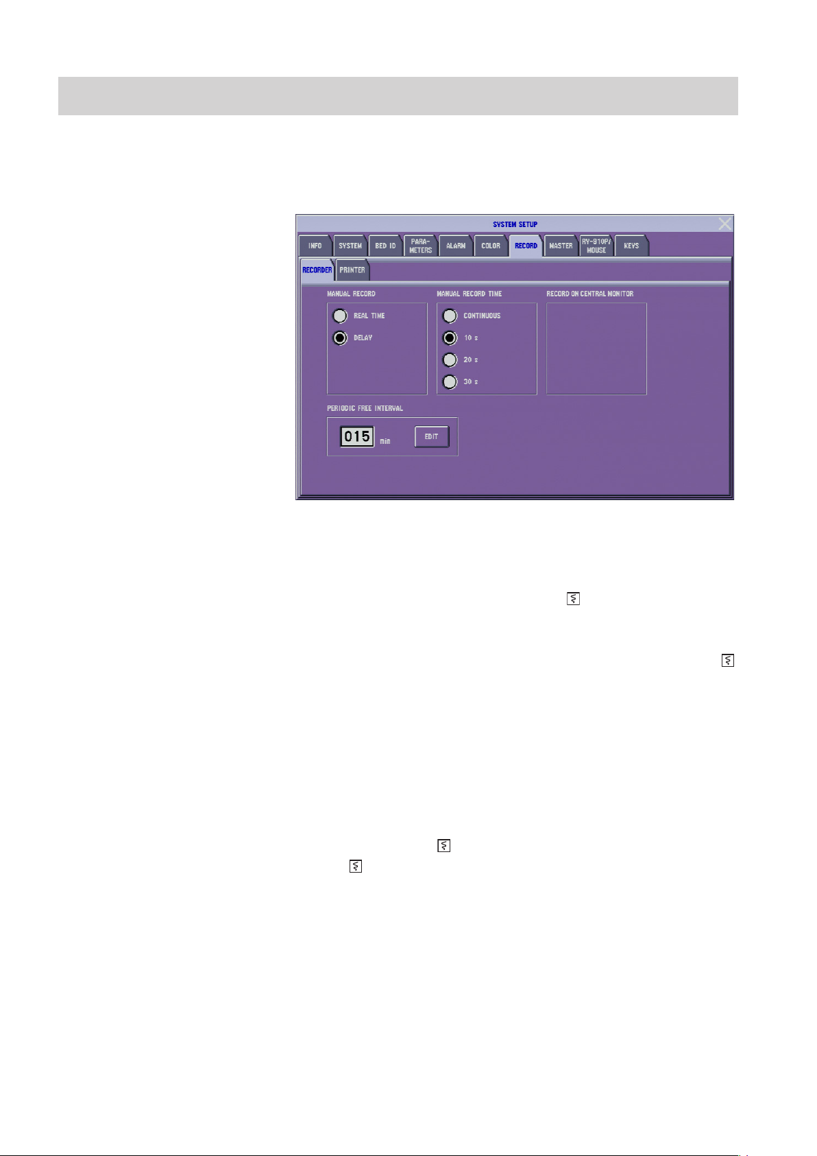
3.40 Administrator’s Guide BSM-6000
3. CHANGING SYSTEM SETUP WINDOW SETTINGS
RECORD Window
The RECORD window has two pages.
RECORDER Page
MANUAL RECORD: REAL TIME, DELAY
There are two manual recording modes.
REAL TIME: The beginning of the recorded waveform is when the RECORD
key on the screen is touched or the [ record] key on the front
panel is pressed.
DELAY: The beginning of the recorded waveform is 8 seconds before the
RECORD key on the screen is touched or 8 seconds before the [
record] key on the front panel is pressed.
When manually recording on a central monitor recorder in the central monitor
networkfrommonitorwithnooptionalrecorder,thissettingisxedatREAL
TIME.
MANUAL RECORD TIME: CONTINUOUS, 10 s, 20 s, 30 s
Select the length for manual recording. When CONTINUOUS is selected, the
recording starts when the [ record] key on the front panel is pressed and stops
when the [ record] key on the front panel is pressed.
When manually recording on a central monitor recorder in the central monitor
network from monitor with no optional recorder, this setting is automatically
changed to 30 s when CONTINUOUS is selected.
PERIODIC FREE INTERVAL: 1 to 120 min
You can select the FREE time interval from 1 to 120 min in 1 min steps for
periodic recording. See “Setting Periodic Recording” in Operator’s Manual or
Section 10 of the User’s Guide Part I.
Page 96

3. CHANGING SYSTEM SETUP WINDOW SETTINGS
1. TouchtheEDITkey.ThePERIODICFREEINTERVALwindowopens.
2. Enter the interval by touching the number keys on the screen.
3
PRINTER Page
3. Touch the ENT key to register the value.
RECORD ON CENTRAL MONITOR
When the bedside monitor has no optional recorder, recording can be performed
on the central monitor recorder in the central monitor network. Select the central
monitor for the remote recording destination from the list of central monitors
(bed IDs).
Change the settings according to the network printer.
PAPER SIZE: A4, LETTER
Select the paper size of the network printer.
Administrator’s Guide BSM-6000 3.41
Page 97

3.42 Administrator’s Guide BSM-6000
3. CHANGING SYSTEM SETUP WINDOW SETTINGS
IP ADDRESS
Set the IP address of the network printer.
1. Touch the EDIT key beside the <IP ADDRESS> box.
2. Use the number keys on the screen to enter the IP address of the network
printer.
3. Touch the SET key to register the IP address.
PRINTER NAME
Enter the printer name. Up to 16 alphanumeric characters can be entered.
Normally, use the default setting “lp”. If data cannot be printed, change the
settingtotheprinternamespeciedintheprintermanual.Iftheprintingstill
cannot be performed, contact your Nihon Kohden representative.
1. Touch the EDIT key beside the <PRINTER NAME> box.
2. Use the alphanumeric keys on the screen to enter the printer name of the
network printer.
3. Touch the SET key to register the printer name.
HOSPITAL
You can print the hospital or institution name at the top of the printing paper. Up
to 32 alphanumeric characters can be entered.
1. Touch the EDIT key beside the <HOSPITAL> box.
2. Use the alphanumeric keys on the screen to enter the hospital name of the
network printer.
3. Touch the SET key to register the hospital name.
Using Network Printer
Printer Settings in the Network
Data of a bedside monitor can be printed on a PostScript network printer which
supports lpr protocol. The settings and network address on the printer must be
set so that PostScript data of the monitor can be printed. The printer must have at
least 32 MB memory. For details about the printer, refer to the printer manual or
contact your Nihon Kohden representative.
For a network printer, we recommend HP LaserJet 4200N or equivalent.
Settings on the Printer
Set the network address on the printer and other settings so that PostScript data
of the monitor can be printed. For the network address, when setting the network
address automatically on the monitors, change the settings as shown below.
When setting the network address manually on the monitors, the network address
of the printer must be different from the network address of the monitors.
Page 98

3. CHANGING SYSTEM SETUP WINDOW SETTINGS
IP address: 010.255.255.250
Subnet mask: 255.000.000.000
Default gateway address: 000.000.000.000
Access control address*: 000.000.000.000
Access control mask*: 000.000.000.000
* HP printers do not have access control address and access control mask
settings.
After changing the settings on the printer, turn the printer power off and on so
that the IP address is recognized by the printer.
The HP LaserJet 4200N printer automatically recognizes PostScript, so there
is no setting for PostScript on this printer. Only the network address (IP
ADDRESS, SUBNET MASK and DEF. GATEWAY) needs to be set on this
printer.
Settings on the Bedside Monitor
Set the settings on the PRINTER page of the SYSTEM SETUP window on the
bedside monitor as follows.
Printer Name*: lp
IP Address: Set the printer’s IP address.
* If data cannot be printed when this setting is “lp”, change the setting to
theprinternamespeciedintheprintermanual.Ifprintingstillcannotbe
performed, contact your Nihon Kohden representative.
3
Printer Setting Example
Administrator’s Guide BSM-6000 3.43
Page 99

3.44 Administrator’s Guide BSM-6000
3. CHANGING SYSTEM SETUP WINDOW SETTINGS33. CHANGING SYSTEM SETUP WINDOW SETTINGS
Page 100

MASTER Window
For fast and easy alarm setup, a group of alarm items can be set all together
at one time. This is called an alarm master. For example, there may be typical
alarm settings at your hospital, or you may have certain alarm settings for certain
patients.
Even when alarms are set by an alarm master, individual alarm settings in the
alarm master can still be changed on the ALARM LIMITS or ARRHYTH
ALARM window or the alarm setting in each parameter setup window.
When <AUTO ADMIT> in the SYSTEM CONFIGURATION screen is set to
ON, the alarm settings return to the master settings 30 minutes after the monitor
is turned off. When <AUTO ADMIT> is set to OFF, you can select whether to
save the settings or initialize the master settings.
WARNING
If more than one medical equipment is used together in the same
facility, make sure all equipments have the same alarm default
settings (alarm master). If the medical equipments have different
alarm default settings and when initialized, the alarm settings
differ with the other equipments and alarm cannot be managed
appropriately in the facility. If using different alarm default settings
according to areas or wings in the facility, manage the alarms
appropriately.
MAIN ALARMS/ECG ALARMS/PRESS ALARMS/TEMP ALARMS/GAS ALARMS/OTHER ALARMS Pages
Selected parameter
Upper limit
Upper limit
slider
Setting bar
Lower limit
Lower limit
slider
Administrator’s Guide BSM-6000 3.45
 Loading...