

Page 1

Life Scope® BSM-6000 Series
Bedside Monitor and BSM-1700
Series Transport Monitor
Clinical Reference Guide
Version 08-12+
© 2019 All Rights Reserved
Page 2

us.nihonkohden.com
Page 3

Table of Contents
Introduction 1
Life Scope
BSM-1700 Series Transport Monitor 4
Basic Operating Concepts 6
Admission Procedure 7
Discharge Procedure 8
ECG Monitoring 9
ECG Signal Acquisition – Electrode Placement 9
ECG Signal Acquisition – Skin Preparation 11
ECG Parameter Operations 12
Arrhythmia Analysis 13
ECG Monitoring – Troubleshooting 15
Non-Invasive Blood Pressure (NIBP) Data Acquisition 16
NIBP Parameter Operations 17
NIBP Monitoring - Troubleshooting 18
®
BSM-6000 Series Bedside Monitor 2
Pulse Oximetry (SpO
SpO
SpO
Parameter Operations 21
2
Monitoring - Troubleshooting 24
2
) Data Acquisition 20
2
Respiration (RESP) Data Acquisition 25
RESP (RR) Parameter Operations 26
RESP Monitoring - Troubleshooting 27
End Tidal CO
End Tidal CO
cap-ONE
Data Acquisition Using the TG-920P CO2 Sensor 28
2
Data Acquisition Using the TG-980P/TG-970P
2
®
Sensor 31
CO Parameter Operations for TG-980-P/TG-970-P 32
CO Parameter Operations 33
CO Monitoring - Troubleshooting 34
us.nihonkohden.com
Page 4

Temperature (TEMP) 35
Monitoring Screen Options 36
Vital Signs, Parameter and Arrhythmia Alarms 37
Interbed Alarms 39
Noise Detection 40
ST Alarms 41
Arrhythmia Alarms 41
Atrial Fibrillation Alarm 42
Arrhythmia Troubleshooting - Interventions 43
12-Lead Electrocardiogram/ST Analysis 44
12-Lead ECG Procedure 45
ST Analysis 46
ST Alarms 46
To Change the ST Measurement Points 47
To View Minute to Minute Stored ST Data 47
Invasive Blood Pressure (IBP) 48
IBP Parameter Operations 48
Set Up/Zero IBP (Invasive Blood Pressure) 48
Change IBP Label (On Screen and in Cable) 50
Calculation Method – STANDARD, PEAK 50
IBP Monitoring - Troubleshooting 52
PA Catheter Insertion 53
Perform Hemodynamic Readings 53
CO Monitoring - Troubleshooting 55
Patient Data Review 56
Trend Window 57
Trend Graphs 57
Tables 57
us.nihonkohden.com
Page 5

NIBP Trend 58
HEMO Calculations 58
LUNG Trend 59
Arrhythmia Recall Window 60
Alarm History Window 61
Full Disclosure Window 62
Zoom In Window 62
ST Window 63
12-Lead Window 63
OCRG Window (Oxy-cardio-respiratory-gram) 64
Drug Calculations 65
Drug Calculations Operations 66
LUNG Calculations 67
LUNG FUNCTION Operations 68
Anesthesia Agent Monitoring 69
Recording 71
Transport Function 72
BSM-1700 Series Monitor 73
BSM-1700 Home Screen Display: Standard Mode/Transport Mode 74
Transport Mode 75
Transport Function using the BSM-1700 75
Connecting to the BSM-6000 Series Monitor 76
Menu Window 77
Using ZM-View Function 78
Starting and Ending ZM-View Function 79
System Settings 80
Cleaning and Disinfecting 81
us.nihonkohden.com
Page 6

Introduction
4
Introduction
This Clinical Reference Guide is designed to assist you to learn the
monitors’ basic operations during the pre-implementation training class or
as a self-study tool as you use the system on your clinical unit. It is also
designed as a reference tool when you need a refresher for infrequently
performed procedures.
The procedures in this guide reflect Life Scope TR Bedside Monitor (BSM)
6000 Series and the BSM- 1700 series monitor. Both are based on the use
of the monitor in an adult or pediatric environment. The BSM- 1700 series
monitor operates similarly to the BSM-6000 series and any differences
between the two will be explained at the end of this guide. Otherwise the
basic operation is nearly identical to each other and this guide will serve to
reflect both BSM’s.
The Clinical Reference Guide is an adjunct to the Operator’s Manual and
does not replace it. Please refer to that manual for critical technical and
other specific information, and for additional information as directed in this
guide.
Whenever you see this icon in this guide, a one touch
“shortcut” is available for the particular function. That shortcut
This Clinical Reference Guide is designed to assist you to learn the
monitors’ basic operations during the pre-implementation training class
or as a self-study tool as you use the system on your clinical unit. It is also
designed as a reference tool when you need a refresher for infrequently
performed procedures.
1
The procedures in this guide reflect Life Scope
®
BSM-6000 series bedside
monitor and the BSM-1700 series transport monitor. Both are based on the
use of the monitor in an adult or pediatric environment. The BSM-1700
series monitor operates similarly to the BSM-6000 series and any differences
between the two will be explained at the end of this guide. Otherwise,
the basic operations are nearly identical to each other and this guide will
serve to reflect both BSM’s.
The Clinical Reference Guide is an adjunct to the Operator’s Manual and
does not replace it. Please refer to that manual for critical, technical, and
other specific information, and for additional information as directed in
this guide.
Whenever you see this icon in this guide, a one touch
“shortcut” is available for the particular function. That shortcut is
described with the icon.
For additional assistance, please contact your hospital biomedical
services representative. For technical or clinical product assistance, a tollfree customer support service is provided at 1-800-325-0283.
us.nihonkohden.com
Page 7

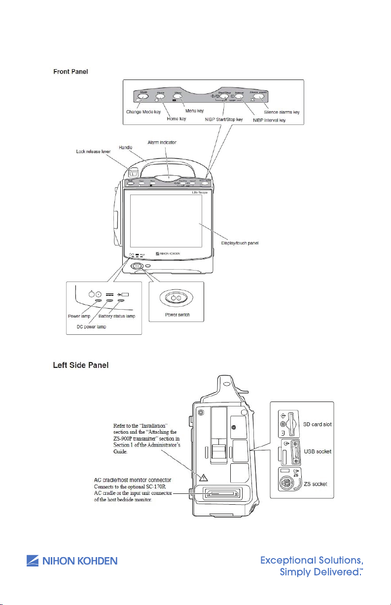
Life Scope® BSM-6000 Series Bedside Monitor
5
Life Scope TR 6000 Series
Bedside Monitor
2
us.nihonkohden.com
Page 8

3
6
The monitor operates on AC power with optional batteries for backup.
When the monitor is operating on battery, the screen brightness can be
dimmed to conserve power.
The batteries are recharged when the monitor is connected to AC power,
and they should be changed every year. Refer to the Operator’s Manual
for additional information.
us.nihonkohden.com
Page 9
BSM-1700 Series Transport Monitor
7
BSM-1700 Series Monitor
4
us.nihonkohden.com
Page 10

5
8
The BSM-1700 series monitor can operate on either battery power or DC
power supplied by the optional cradle. Battery life is approximately 4-5
hours. When not in use, it is recommended to keep the BSM-1700 docked
in the cradle and plugged in to charge.
us.nihonkohden.com
Page 11
Basic Operating Concepts
9
Basic Operating Concepts
Normally, the monitoring screen is displayed on the bedside monitor. Key
operations are performed on the touch screen display using a gentle touch
with the fingertip or touch pen, the infrared remote controller, or a computer
mouse that is connected to the USB port: 1) Touch (or click) the
PARAMETER VALUE to enter the parameter menus, 2) Touch (or click)
the PATIENT NAME area to enter the PATIENT INFO menu, 3) Touch a
FUNCTION KEY in the upper left corner to access frequently used
functions.
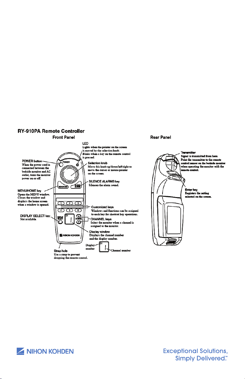
The BSM-6000 and 1700 Series bedside monitors have an optional
infrared remote controller:
Normally, the monitoring screen is displayed on the bedside monitor. Key
operations are performed on the touch screen display using a gentle
touch with the fingertip or touch pen, the infrared remote controller, or a
computer mouse that is connected to the USB port: 1) Touch (or click) the
PARAMETER VALUE to enter the parameter menus; 2) Touch (or click) the
PATIENT NAME area to enter the PATIENT INFO menu; 3) Touch a FUNCTION
KEY in the upper left corner to access frequently used functions.
The BSM-6000 and -1700 Series bedside monitors have an optional infrared
remote controller:
6
The MENU window can be displayed by pressing the MENU key on the
front panel or on the remote controller. When you access a function on
the monitor, the menu is displayed in a tabbed “file folder” format. Touch
or click on the tab to access the individual menu. The monitoring screen
can be displayed at any time by pressing the HOME key on the front
panel or on the remote controller.
us.nihonkohden.com
Page 12

Admission Procedure
The Life Scope BSM 6000 Series bedside monitor is ready for data
collection once the power is turned ON.
1. Press the power switch and release — the monitoring screen
appears after monitor warms up.
2. Verify the alarm settings and input unit (see VITAL SIGNS,
PARAMETER, and ARRHYTHMIA ALARMS section in this guide).
3. Connect the patient.
4. Enter patient demographic information (optional).
a. Press the MENU key
b. Touch the ADMIT button in the PATIENT section on the menu
OR Touch the patient name field at the top of the screen
c. Select the patient type (Adult, Pediatric, or Neonate),
if necessary.
i. Selecting each patient type will set the vital sign alarm
limits, arrhythmia alarm settings, NIBP initial cuff inflation
pressure, invasive pressure scales, QRS detection type, and
trend graph scales, based on the patient type.
7
d. Touch the NAME data button and/or touch the PATIENT ID
e. Enter the patient name and/or number using the
on-screen keyboard.
f. DEL clears all characters to the right of the cursor.
g. BS erases to the left of the cursor, one character at a time.
h. Touch the ENTER button to enter the patient name or number.
i. If demographics are entered after patient monitoring has
commenced, do not press the ADMIT key. Data loss could
occur if this action is performed post demographic entry.
Press the HOME key to return to the monitoring screen. If the bedside
monitor is a part of a network with a central nursing station (CNS),
the information can be entered at the central station using the
ADMIT/DISCHARGE menu.
us.nihonkohden.com
Page 13

Discharge Procedure
4
Introduction
This Clinical Reference Guide is designed to assist you to learn the
monitors’ basic operations during the pre-implementation training class or
as a self-study tool as you use the system on your clinical unit. It is also
designed as a reference tool when you need a refresher for infrequently
performed procedures.
The procedures in this guide reflect Life Scope TR Bedside Monitor (BSM)
6000 Series and the BSM- 1700 series monitor. Both are based on the use
of the monitor in an adult or pediatric environment. The BSM- 1700 series
monitor operates similarly to the BSM-6000 series and any differences
between the two will be explained at the end of this guide. Otherwise the
basic operation is nearly identical to each other and this guide will serve to
reflect both BSM’s.
The Clinical Reference Guide is an adjunct to the Operator’s Manual and
does not replace it. Please refer to that manual for critical technical and
other specific information, and for additional information as directed in this
guide.
Whenever you see this icon in this guide, a one touch
“shortcut” is available for the particular function. That shortcut
The discharge procedure is performed between patients to delete
information from the bedside monitor and the CNS and to reset default
alarm settings on both monitors. When this procedure is not performed,
the most current 24 hours of data is stored in memory. The amount of
time that data is stored after power is turned off on the bedside monitor
depends on the setup functions. Once the information is deleted, it
CANNOT be retrieved.
To discharge a patient:
1. Press the MENU key
2. Touch the ADMIT button in the PATIENT section in the menu
OR Touch the patient name field at the top of the screen
3. Touch the DISCHARGE tab
4. Touch YES to confirm. This procedure readies the monitor for the
next patient’s admittance.
5. Turn the monitor power off, if needed (press and hold the power
switch for 3 seconds until the display blanks).
8
A “COMMUNICATION LOSS” message displays on the central station when
the bedside monitor is turned off.
Suspend Monitoring
The SUSPEND MONITORING function is used to suspend data processing and
alarms during temporary interruptions in monitoring. No patient information
is deleted with this procedure, but the monitoring screen remains active and
alarms are suspended while the patient is disconnected.
1. Disconnect the patient from the monitor.
2. Press the MENU key.
3. Touch the SUSPEND MONITORING button in the ALARM section.
The menu closes and the “SUSPEND MONITORING ALL ALARMS OFF”
message appears. Monitoring resumes automatically once the patient is
reattached, depending on the configured time interval.
A SUSPEND MONITORING function button may be present on the
screen and/or the remote for a one-touch function.
us.nihonkohden.com
Page 14
ECG Monitoring
12
12
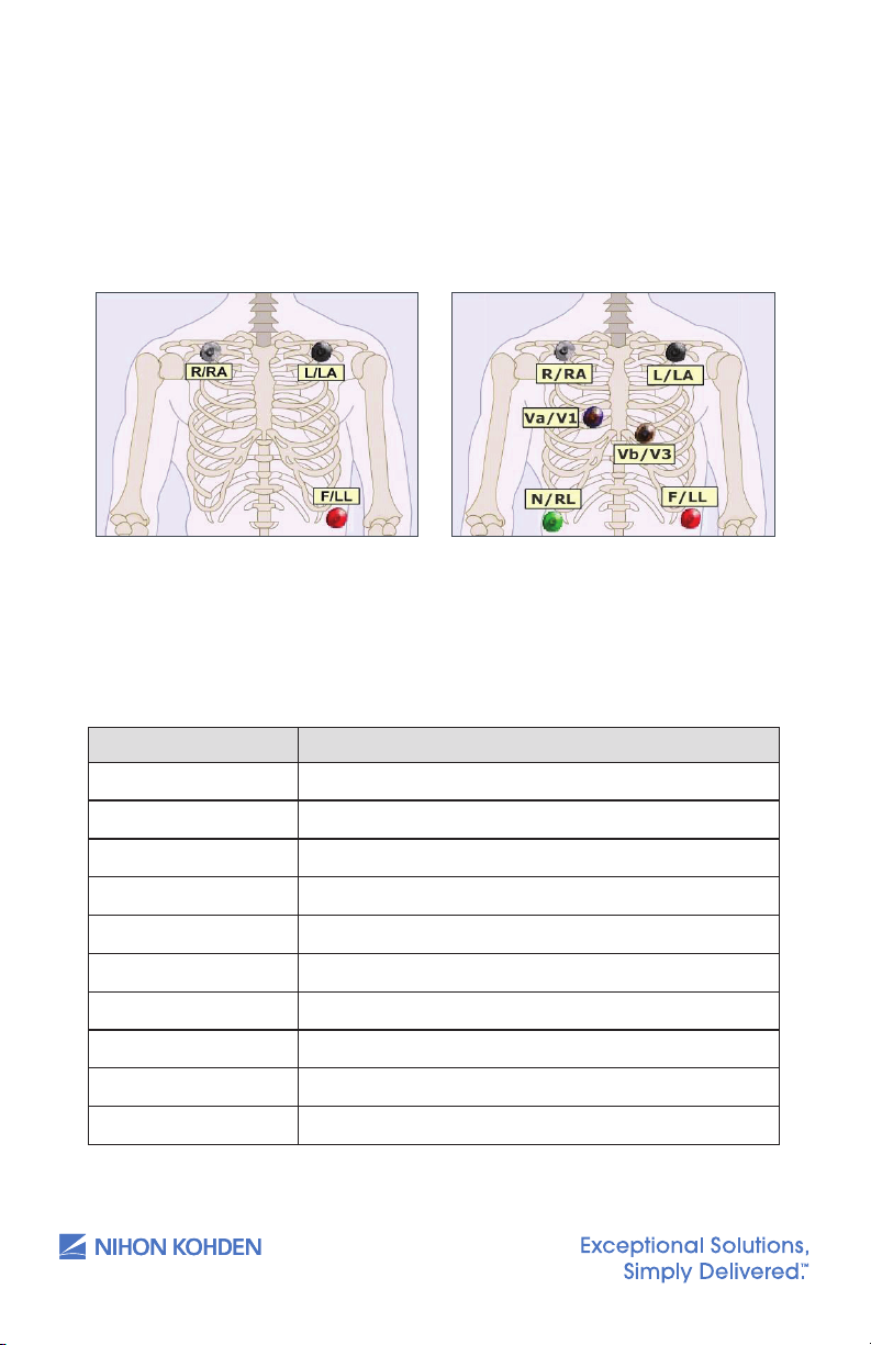
ECG Signal Acquisition – Electrode Placement
The Life Scope G9 bedside monitor is equipped to use 3, 6, or 10
electrodes to monitor heart rate, rhythm, and ST segments, as well as
impedance respiration.
9
Chest electrodes may be placed in any chest lead position, depending on
the monitoring requirements. V1 and V3 are shown. V1 is useful for arrhythmia
monitoring. V3 is the most sensitive lead for anterior wall ischemia. Other Vleads are useful for ST segment and arrhythmia monitoring as well.
*Default V leads
3 Electrode Placement
Chest Lead Position
R/RA (white) Midclavicular line 2 fingers below R clavicle
L/LA (black) Midclavicular line 2 fingers below L clavicle
N/RL (green) R anterior-axillary line at edge or lower rib
F/LL (red) L anterior-axillary line at edge of lower rib
*V1 (blue) 4th inter-costal space(ICS), right sternal border
V2 4th ICS, left sternal border
*V3 (orange) Halfway between V2 and V4
V4 5th ICS, left mid-clavicular line
V5 Anterior axillary line at same level as V4
V6 Mid-axillary line at same level as V4
6 Electrode Placement
us.nihonkohden.com
Page 15

The 10-electrode ECG cable is used to perform diagnostic-quality
13
12-lead electrocardiograms, as with an ECG cart. Electrode placement
for the procedure on the bedside monitor should be the same as the
cart procedure to provide consistency for serial comparison between
ECGs. Electrode placement is suggested here but should be decided by
individual hospital protocols. Tab or patch electrodes may be used.
10
10 Electrode Placements
Limb electrodes should be placed on the actual limbs if the hospital
protocols require this placement for diagnostic 12-lead ECG samples.
Continuous 12-lead monitoring is difficult with the limb leads on the
extremities because of the motion artifact, so use the torso limb
placement for continuous monitoring, when possible.
See the 12-lead ECG section in this guide for the 12-lead procedure.
us.nihonkohden.com
Page 16

ECG Signal Acquisition – Skin Preparation
14
The ECG waveform is monitored for heart rate, arrhythmias, ST segment
measurements, and pacemaker activity. Electrical impulses are
conducted through the gel on the ECG electrodes, so moist gel is
required for proper detection. Inadequate detection can cause electrical
noise on the ECG tracing and inaccurate interpretation by the monitor.
We recommend that electrodes be changed at least daily to promote
adequate signal detection but follow the recommendations of your
electrode manufacturer and/or hospital policy.
Proper skin preparation is also important for respiration monitoring, as the
respiration parameter uses the same electrodes. It is most important to
remove hair and dead skin cells for accurate detection, and to remove
skin oils so the electrodes will adhere to the patient’s skin.
1. Select the electrode site according to the diagram above.
2. Trim excess hair according to hospital protocols.
3. Gently abrade skin areas with dry gauze to remove dead skin cells.
4. If skin is oily, clean the site with soap/water and friction and then wipe
off with dry gauze. You may use an alcohol prep according to your
policy, if needed.
11
5. Attach the lead wire to the electrode.
6. Attach the electrode to the patient, pressing the circumference of
electrode to secure it.
7. Position the ECG cable to prevent tangling.
Stress Loop: The lead wires can transmit electrical interference to the
monitor; to minimize this interference with patient movement, fasten the
individual lead wire to the skin with surgical tape.
us.nihonkohden.com
Page 17

ECG Parameter Operations
4
Introduction
This Clinical Reference Guide is designed to assist you to learn the
monitors’ basic operations during the pre-implementation training class or
as a self-study tool as you use the system on your clinical unit. It is also
designed as a reference tool when you need a refresher for infrequently
performed procedures.
The procedures in this guide reflect Life Scope TR Bedside Monitor (BSM)
6000 Series and the BSM- 1700 series monitor. Both are based on the use
of the monitor in an adult or pediatric environment. The BSM- 1700 series
monitor operates similarly to the BSM-6000 series and any differences
between the two will be explained at the end of this guide. Otherwise the
basic operation is nearly identical to each other and this guide will serve to
reflect both BSM’s.
The Clinical Reference Guide is an adjunct to the Operator’s Manual and
does not replace it. Please refer to that manual for critical technical and
other specific information, and for additional information as directed in this
guide.
Whenever you see this icon in this guide, a one touch
“shortcut” is available for the particular function. That shortcut
The heart rate is calculated by using a moving average or by counting
each individual beat. The AVERAGE mode uses an average of 12 beats
and updates them with each new beat to display the new average every
3 seconds. The INSTANT mode updates the heart rate with each beat and
displays the new rate every 3 seconds.
The ECG menu allows adjustments while monitoring ECG. To access the
ECG parameter menu, touch the heart rate value.
MAIN Tab Options:
Sensitivity – Increases or decreases the size of the ECG tracings.
1. Touch x1/4, x1/2, Auto, x1, x2, or x4. Ensure correct electrode
a. Auto allows the monitor to set a sensitivity that is required for
detection based on the previous 16 beats.
Lead – The top lead is analyzed for arrhythmias when SINGLE arrhythmia
analysis is selected; the top two leads are analyzed with MULTIPLE. Ensure
correct electrode placement and then select the option to display the
lead with QRS complexes that are > 5 mm tall.
placement and then select the option to display the QRS at > 5 mm tall.
12
Touch the desired lead to display in the top position — unavailable leads
are grayed out.
Alarms – HEART RATE/VPC/ST
Increase, decrease, or turn OFF alarm limits
1. Touch limit and then
2. Touch limit and then
Change alarm limit by touching and dragging the slider.
LEARN
Initiates a “relearn” of the patient’s dominant QRS for arrhythmia processing
and the “LEARNING” message is displayed on screen. Use this function
whenever the patient’s rhythm has changed, incorrect detection occurs, or
to store a new dominant template in the MAIN or ARRHYTHMIA ANALYSIS tabs.
ST ALARMS tab: allows for setting alarms on all monitored leads.
Provides alarm settings for individual or ALL leads. Individual settings set
alarms relative to iso point; ALL sets relative to current ST measurements.
us.nihonkohden.com
s
to increase
t
to decrease OR
Page 18

Arrhythmia Analysis
Arrhythmia alarms occur when ARRHYTHMIA ANALYSIS is turned on in the
ARRHYTH ANALYSIS tab, the individual arrhythmia alarm is turned to ON,
and the monitor detects an arrhythmia event. Single (top) or multiple (top
two) ECG leads are selected for analysis in the ARRHYTH ANALYSIS tab.
To view or change these settings:
1. Touch the heart rate value.
2. Touch the ARRHYTH tab.
3. Touch the ON button for the arrhythmia events you want to alarm.
OTHER Tab Options:
Filters – DIAG, MONITOR, MAXIMUM
Filters reduce AC interference on the ECG waveform. MONITOR should be
chosen for routine patient monitoring.
HUM Filter – ON/OFF
HUM filters reduce interference on the ECG waveform during battery
operation. ON should be chosen for routine patient monitoring with the
monitor plugged into AC power.
Number of Electrodes
Signals the monitor to the type and numbers of ECG lead wires. Choose
STANDARD for Nihon Kohden lead blocks. Use INDIV 6 or INDIV 10 when
using individual or disposable lead wires.
13
ECG Measurement – ON/OFF
This option is available if SpO
and pulse rate monitoring are needed and
2
can only be turned off if no ECG signal is detected. Turn OFF to view only
SpO
and SpO2 PR when patient is connected to SpO2 probe and monitor.
2
Sync Pitch – FIXED, SpO
Provides a variable change in the audible tone as the SpO
, PRESS
2
value
2
changes. FIXED does not change as the value changes.
Sync Source – ECG, SpO
, PRESS
2
Provides the sync sound from the selected pulse source. If the QRS SYNC
function is enabled, a green light on top of the monitor also flashes with
each pulse.
When SpO
or PRESS is selected, the associated pulse rate is displayed in
2
the corresponding color when the PR is ON. This is helpful in OR when the
cautery is in use. SYNC SOUND VOLUME is controlled in MENU > VOLUME.
us.nihonkohden.com
Page 19

HR Display Mode – AVERAGE, INSTANT
Two modes that can be used to calculate heart rate:
AVERAGE – Monitor detects 12 consecutive beats (including VPCs),
averages the R-R intervals, and uses this average to calculate the current
HR. When a new beat is detected, the HR is recalculated using the latest
12 beats. The HR display is updated every 3 seconds.
INSTANT – HR is calculated based on the last 2 beats and is updated every
3 seconds.
Pacing
Detection – ON/OFF
Turn this to ON when the patient has a pacemaker. This tells the monitor
to detect the pacer spike and look for capture following that spike. False
arrhythmia alarms could occur if detection is left OFF with an internal
pacemaker present.
Mark – ON/OFF
Turn this ON to enhance the pacer spike ON SCREEN. The enhanced spike
is not printed.
14
Auto Lead Change – ON/OFF
This option is available with the 6 or 10 electrode cable. This allows for the
monitored lead to automatically change between lead I, II, and III if lead
wires or electrodes become disconnected for more than 5 seconds.
ECG 2/3 Waves Tab:
This allows you to select the numbers of ECG leads to display (1, 2, or 3), the
lead to display in each position, and to change the sensitivity on the second
and third leads. Choose the primary (top) ECG lead in the ECG MAIN tab.
V-Leads Tab:
This allows you to assign the V-leads for the Va and Vb chest leads when
using the 6 electrode cable. Once the leads are assigned, they become
available on the ECG 2/3 Waves tab.
ST Point Tab:
This allows you to adjust the measurement points from the default settings
and the markers show the iso, r-wave, j-point, and ST point. Use the < >
keys for changes.
us.nihonkohden.com
Page 20

ECG Monitoring – Troubleshooting (see operator manual)
Problem Possible Cause Action
Inaccurate HR QRS is too small Change sensitivity so QRS is >
5 mm tall
Arrhythmia alarm
occurs frequently
when HR is normal
ECG waveform
does not appear
on screen when
electrodes are
properly attached
AC interference
on the waveform
Baseline
wandering
QRS is not detected
correctly
Dominant QRS is
not appropriate for
arrhythmia monitoring
Patient moved or EMG
noise is superimposed
NUMBER OF
ELECTRODES setting
in ECG MENU is not
correct
Electrode is dry Change electrode(s)
ECG FILTER is set to
DIAGNOSTIC
Baseline is not stable
due to respiration
or movement
The electrode is dry Change electrodes
Change to different lead with a
tall QRS and small T wave (View
all leads of available ECG in the
12-Lead Analysis tab)
Learn ECG or change the
ECG lead
Move electrodes to positions with
less muscle. Use stress loops.
Set correct number of electrodes
for attached ECG cable. Use
STANDARD unless individual lead
wires are used.
Set ECG FILTER to MONITOR or
MAXIMUM
Move electrodes to positions with
less muscle. Consider stress loops.
15
Inaccurate
pacemaker
detection or false
VPC calls for
paced beats
us.nihonkohden.com
Contact resistance
between skin and
electrode is high
The ECG filter is set to
DIAGNOSTIC
Pacemaker impulse
is not detected and/
or paced beats
are labeled as
ventricular
Abrade skin gently with dry gauze
before applying electrodes
Set the ECG filter to MONITOR or
MAXIMUM
Ensure PACING DETECTION is ON.
Display a different ECG lead, such
as V1. Try alternate electrode
placement: Move LL up and
RA down.
Page 21

Non-Invasive Blood Pressure (NIBP)
19
Data Acquisition
The Nihon Kohden NIBP monitor uses the occlusive-oscillometric method
to measure systolic, diastolic, and mean arterial non- invasive blood
pressure. This method may yield dierent results from direct, invasive
arterial pressure.
The initial adult inflation volume is 180mmHg, pediatric is 140mmHg, and
then subsequent inflations are 30mmHg above the last systolic reading.
ADULT/CHILD is displayed in the NIBP numeric area when that hose/cuff is
connected.
The monitor automatically detects the neonatal hose when connected
and displays a “NEONATAL” message in the NIBP numeric area. The
initial neonatal inflation volume is 70-100mmHg (based on system
configuration), and then subsequent inflations are 30mmHg above the last
systolic reading.
The NIBP is measured from the change in amplitude pattern of pulsatile
oscillation in cuff pressure as the cuff pressure is reduced from above
systolic to below diastolic pressure. The systolic pressure is the pressure
at which the pulsatile oscillation suddenly increases, and the diastolic
pressure is the pressure at which the pulsatile oscillation suddenly
decreases. The mean arterial pressure is the point where maximum
pulsatile oscillation occurs.
16
INACCURATE READINGS MAY OCCUR DURING PATIENT MOVEMENT.
Cuff selection should be based on the size of the patient’s arm. The
American Heart Association recommends that the cuff width be 40% of
the circumference of the upper arm. Inappropriate cu size can result in
inaccurate NIBP results.
us.nihonkohden.com
Page 22

NIBP Parameter Operations
4
Introduction
This Clinical Reference Guide is designed to assist you to learn the
monitors’ basic operations during the pre-implementation training class or
as a self-study tool as you use the system on your clinical unit. It is also
designed as a reference tool when you need a refresher for infrequently
performed procedures.
The procedures in this guide reflect Life Scope TR Bedside Monitor (BSM)
6000 Series and the BSM- 1700 series monitor. Both are based on the use
of the monitor in an adult or pediatric environment. The BSM- 1700 series
monitor operates similarly to the BSM-6000 series and any differences
between the two will be explained at the end of this guide. Otherwise the
basic operation is nearly identical to each other and this guide will serve to
reflect both BSM’s.
The Clinical Reference Guide is an adjunct to the Operator’s Manual and
does not replace it. Please refer to that manual for critical technical and
other specific information, and for additional information as directed in this
guide.
Whenever you see this icon in this guide, a one touch
“shortcut” is available for the particular function. That shortcut
1. Ensure the appropriate cuff size for the patient and position extremity
at heart level, as readings may vary with a cuff higher or lower than
this position. Monitor automatically identies hose connected
(ADULT/CHILD, NEONATE) and displays that on screen.
2. Press the NIBP INTERVAL key to display the automatic interval options
and select the desired interval.
3. Press the NIBP START/STOP key to initiate reading.
Single NIBP readings can be started at any time using the NIBP
START/STOP key
To access the NIBP parameter menu, touch the NIBP value.
MAIN Tab Options:
Initial Cu Pressure Type:
This allows you to choose ADULT or CHILD to adjust the initial inflation
pressure. Subsequent inflations are 30mmHg over the last systolic reading.
Measurement Interval – Manual to 8-hour
Touch the desired interval and then press the NIBP START/STOP key to
initiate the automatic readings. Inflation may start automatically if
configured to do so.
17
•
STAT mode takes continuous readings for 10 minutes as set in
the setup menu (view in NIBP Mode tab).
SIM mode is available in the OR mode and allows for staged
readings as set in the setup menu (view in NIBP Mode tab).
NIBP intervals may be set using the NIBP INTERVAL key.
Alarms – SYSTOLIC, DIASTOLIC, MAP
Increase, decrease, or turn OFF alarm limits
1. Touch limit then
2. Touch limit then
Set value to ABOVE MAXIMUM or BELOW MINIMUM to turn alarm OFF.
PWTT Tab: ON/OFF – choose to set the trigger time in minutes. Available
with NK SpO
when SpO
us.nihonkohden.com
•
s
to increase
t
to decrease
monitors and allows for automatic blood pressure readings
2
indicates a change in blood pressure.
2
Page 23

OTHER Tab Options:
Target Cu Pressure – Adjusts inflation volume. Use this for patient
comfort before the cuff inflates.
Display Oscillation Graph – Graph shows the detected pulse amplitude
on a pressure scale and can be used to determine if the reading was
affected by patient movement or other interference. Can be turned ON/
OFF. (Graph only displayed on home screen if there is enough room.)
NIBP Monitoring – Troubleshooting (see operator manual)
Problem Possible Cause Action
Cuff inflation
pressure is <
10mmhg or NIBP
data disappears for
a few seconds
Cuff does not inflate
when NIBP START/
STOP key is pressed
Abnormal
measurement results
are displayed
Auto measurement
does not start even
when time interval
has passed
Cuff suddenly
inflates
Cuff hose is not
connected to monitor
socket properly
Hose is not connected
to socket
Cuff size is incorrect Select cuff size appropriate to
Cuff is not wrapped
correctly
Patient movement Take readings without patient
Measurement on
wrong site
Time interval is set
incorrectly or NIBP
START/STOP key was
not pressed to set
interval
Measurement mode is
set to AUTO
NIBP measurement is
triggered by PWTT
Connect hose to monitor
properly
Connect the hose to socket
firmly
patient’s size
Position cuff snuggly on
patient’s arm
movement
Position cuff over artery
Check interval and press NIBP
START/STOP key
Check time interval
PWTT TRIGGERED NIBP is set to a
threshold on the SYSTEM SETUP
screen
18
us.nihonkohden.com
Page 24

Problem Possible Cause Action
“MEASURE TIME OUT”
message
“SYSTOLIC OVER”
message is displayed
Cannot measure
NIBP
Patient movement or
irregular pulse
Blood pressure is
higher than the
NEONATAL mode can
detect
Noise interfered with
calculation of NIBP
Pulse wave is unstable
due to arrhythmias
Cu or hose has leak Change cu or hose
Reposition, retry, or use another
method
Change to the ADULT/CHILD
hose and use the appropriately
sized cuff for the infant.
Remove cause
Check blood pressure using
alternative methods
19
Blood congestion
occurs
Thrombus occurs
NIBP data on the
screen is dark
“CHECK CUFF AND
HOSE” message is
displayed
“PATIENT MOVEMENT
REMEASURING”
message is displayed
Measuring over long
periods of time at
intervals less than2.5
minutes
Sickle cell patients NIBP is contraindicated on sickle
10 minutes elapsed
from last reading
Cu or hose has leak
or is hose is bent or
obstructed
Patient moved during
measurement
Patient moved during
measurement or pulse
is too small to detect.
Cu is not appropriate
for patient or is
attached incorrectly
Increase measuring interval
Use alternate site for NIBP
measurements
cell anemia patients
NIBP data returns to normal
brightness with next reading
Check cu and hose for leaks or
straighten hoses
Wait for patient to stop moving
and measure again
Wait for patient to stop moving
and measure again
Check that cu is appropriate
and positioned correctly
us.nihonkohden.com
Page 25

Pulse Oximetry (SpO2) Data Acquisition
23
2
cable, which accepts
The Nihon Kohden SpO2 monitor uses a SpO2 cable, which accepts
reusable or disposable probes. The monitor comes in three options for
pulse oximetry: Nihon Kohden, Nellcor OxiMax, and Masimo. The menu
options vary slightly depending on the algorithm used.
Nihon Kohden probes are obtained from Nihon Kohden, but Nellcor and
Masimo probes are obtained from those companies directly. There are
many options for probes from each company, ranging from neonate to
adult, and it is important to use the appropriate probe for the size and
age of the patient. There are options for probes that are used on the
ear and forehead, in addition to the traditional foot or hand and finger
probes. See the operator manual for additional information.
The probe is positioned with the photo emitter (cable side) on top so light
is passed through the measurement site to the photo detector directly
opposite the emitter. Results are best if used on fingers without nail
polish or acrylic nails. Ambient light may affect readings, so placing the
extremity under cover may improve detection.
20
When measuring SpO
for long periods of time, it is recommended that
2
the site be alternated to relieve pressure on the measuring digit.
Change site every four hours for reusable and every four to eight hours for
disposable probes. Discontinue use of probe if skin irritation occurs or signs
of circulatory compromise.
The SpO
monitor is able to “read through”
2
motion and alerts you to this condition by
placing an “M” on the screen.
The Masimo version uses this symbol to indicate
a “low Signal IQ” that is discussed below.
us.nihonkohden.com
Page 26

SpO2 Parameter Operations
To access the SpO2 parameter menu, touch the SpO2 value.
MAIN Tab Options:
Sensitivity – X1/8 to X8 – AUTO finds the appropriate size and adjusts the
size of the SpO
Touch the setting and observe the waveform in the SpO
waveform on the screen and on the recording paper.
2
window.
2
21
Alarms – SpO
Alarm Limits
2
Increase, decrease, or turn OFF alarm limits.
1. Touch limit then
2. Touch limit then
s
to increase
t
to decrease
Set value to ABOVE MAXIMUM or BELOW MINIMUM to turn alarm OFF.
OTHER Tab Options:
Sync Source – ECG, SpO2, PRESS
Provides the sync sound from the selected pulse source. If the QRS
SYNC function is enabled, a green light on top of the monitor also
flashes with each pulse. WHEN SpO
ASSOCIATED PULSE RATE IS DISPLAYED IN THE CORRESPONDING COLOR
WHEN THE PR IS ON. This is helpful in OR when the cautery is in use.
SYNC SOUND VOLUME is controlled in MENU>VOLUME.
Sync Pitch – FIXED, SpO
, PRESS
2
Provides a variable change in the audible tone, as the SpO
changes and can be configured in one of two ways. FIXED does not
change as the value changes.
OR PRESS IS SELECTED,THE
2
value
2
SPO2 VALUE Sync Pitch of Sync Sound
100 to 81% High to low pitch, in 1% steps
100 to 40% High to low pitch, in 1% steps
Less than 81%
or less than 40%
us.nihonkohden.com
Low Pitch
Page 27

Nihon Kohden Monitors Only
Response - FAST, NORMAL, SLOW
There are three response modes in the Nihon Kohden version of the BSM.
Each uses a different time to ensure accurate measurements according
to patient conditions. When measurement conditions are unstable, the
response becomes slower in all modes.
FAST: Select this mode for special applications that require a fast
response time, such as with short apnea episodes.
NORMAL: Select this for normal monitoring.
22
SLOW: Select this when you need to suppress a rapid change in SpO
.
2
Masimo Monitors Only
Perfusion Index
Indicates the percentage of pulsatile (arterial) to non-pulsatile (venous)
signals. The range of Perfusion Index is 0.02% (very weak pulse strength)
to 20% (very strong pulse strength). Placing the sensor at the site with the
highest Perfusion Index number improves the performance during motion.
Perfusion Index Display
To display the Perfusion Index, press the SpO
Press ON/OFF tab for PI DISPLAY. The PI will be displayed next to the
associated SpO
value.
2
Signal IQ
The signal quality indicator is used to identify the occurrence of the pulse
and the associated signal quality of the measurement. The Signal IQ,
shown as a vertical line, coincides with the peak of the arterial pulsation on
the waveform. The height of the line indicates the quality of the measured
signal. When the signal quality is very low, the height of the line becomes
low and a “M” is displayed along with the SpO
tab, then NUMERIC DISPLAY.
2
value on the monitor.
2
us.nihonkohden.com
Page 28

Averaging Time (SEC) – 2, 4, 8, 10, 12, 14, 16
This is the averaging time for the SpO
the pulse continuously and displays the average SpO
value. The monitor samples
2
based on this
2
selection. Longer average times produce more stable numbers. Shorter
average times display more changes in the SpO
values and may detect
2
rapid changes in the patient’s condition.
Sensitivity Mode – MAX, NORMAL, APOD
These settings provide more options for improving readings. MAX should
be used when obtaining the reading is most difficult. It is designed to
detect with the weakest signals. NORMAL provides the best combination
of sensitivity and probe-off detection. APOD (adaptive Probe Off
Detection) is the least sensitive for low perfusion states but is the best
detection for “probe-off” conditions.
Fast Sat – ON/OFF
Enables rapid tracking by minimizing averaging times. This setting is
helpful during induction, intubation, and sleep studies.
23
us.nihonkohden.com
Page 29

SpO2 Monitoring – Troubleshooting (see operator manual)
Problem Possible Cause Action
Unstable SpO2 value Probe size is not
appropriate
Probe is on same limb as
NIBP
An ESU is used Locate ESU as far as possible from
Measuring on venous
pulse
value on
SpO
2
monitor and CO
oximeter do not
match
2
Probe is not positioned
appropriately
Site is inappropriate Attach probe to site 6-14 mm
Measuring site is not
clean
Too much abnormal
hemoglobin (HbCO,
MetHb, etc.)
Dye is injected in blood Cannot measure correctly
Use correct probe
Use another limb
probe; wait for pulse wave to
stabilize
Reposition probe
Position probe with emitter and
detector facing each other
thick
Remove nail polish or use
alternate site
Cannot measure correctly
24
Measuring during CPR Cannot measure correctly
Probe is damaged Probe is disinfected
by an unspecified
procedure
See manufacturer’s
recommendations for specified
procedure
Probe is used repeatedly Replace probe
MODULE
“SpO
2
FAILURE” message
Probe is damaged Turn off monitor, replace probe,
turn on monitor
appears
“DETECTING PULSE”
message is displayed
for a long time
Detected pulse is too
small to measure.
Reposition probe; consider Masimo
controls for average time, sensitive
Mode, and Fast Sat
Noise on waveform Light interference Cover site with blanket
Line frequency on
Set line frequency correctly
monitor is incorrect
No SpO
data on
2
screen
“M” message
appears
us.nihonkohden.com
SpO2 connection cord is
not connected
Displayed with
considerable body or
probe movement
Connect OEM-10 connection
cord
Change probe site; consider
Masimo controls for average time,
sensitive mode, and Fast Sat
Page 30

Respiration (RESP) Data Acquisition
28
1.
It is preferable to place the LL electrode
on the lowest left rib at the anterior
axillary line. This position is used for
most patients when the LL electrode
positioning is important for ECG
monitoring. Select R-F.
2.
Movement of the chest influences
respiration measurement. This position
is used for patients with rapid, shallow
respirations. Select R-L.
3.
This position is used for improved
respiration detection and is
recommended when respiration
monitoring is a priority. The respiration
amplitude is larger and more easily
detected. The LL electrode is positioned
higher on the chest at the 5th ICS, left
mid-axillary line. Select R-F.
The flashing lungs are the breath indicators. When the monitor
detects the rise (inspiration) and fall (exhalation) in a respiratory
The Nihon Kohden monitor uses the ECG monitoring system to detect
respiration using the thoracic impedance method. This method measures
changes in impedance between the right arm and left leg electrodes
(ECG Lead II - R and F) or right arm and left arm electrodes (ECG Lead I R and L). Movement in the chest and abdomen influences measurement,
and amplitude varies greatly depending on placement of the electrodes.
Repositioning of the ECG electrodes may be necessary for optimal
respiration monitoring.
It is preferable to place the LL
electrode on the lowest left rib at
the anterior axillary line. This position
is used for most patients when the LL
electrode positioning is important for
ECG monitoring. Select R-F.
Movement of the chest influences
respiration measurement. This position
is used for patients with rapid, shallow
respirations. Select R-L.
25
This position is used for improved
respiration detection and is
recommended when respiration
monitoring is a priority. The respiration
amplitude is larger and more easily
detected. The LL electrode is positioned
The flashing lungs are the breath indicators. When the monitor
detects the rise (inspiration) and fall (exhalation) in a respiratory
cycle, it flashes the lungs and adds the breath to its rate. The rate
displayed is a moving number that updates every three seconds and is
based on the previous detected breaths.
The keys to accurate respiratory detection are 1) fresh electrodes; 2) the
recommended electrode placement; 3) the appropriate respiratory lead
selection; and 4) the appropriate sensitivity for the patient.
us.nihonkohden.com
higher on the chest at the 5th ICS, left
mid-axillary line. Select R-F.
Page 31

RESP (RR) Parameter Operations
29
2
Alarm Limits
To access the RESP parameter menu, touch the RR value.
MAIN Tab RESP Options:
Imp Resp Lead – R-L (ECG lead I) /R-F (ECG lead II) Selects RESP
measurement electrode (see RESP Introduction in this guide)
Sensitivity – X1/4 To X4
Determines the size of RESP waveform onscreen and the recording paper
26
Alarms – RESP/APNEA/CO
alarm limits
1. Touch limit then
2. Touch limit then
Set value to ABOVE MAXIMUM or BELOW MINIMUM to turn alarm OFF.
Apnea alarm is set for seconds [s] without respiration detection.
When alarm limit is turned OFF, there is no APNEA alarm.
Alarm Limits Increase, decrease, or turn OFF
2
s
to increase
t
to decrease
OTHER Tab Options:
Imp Resp Measure – ON/OFF
Turns RESP monitoring ON or OFF.
Waveform, value, and alarms are unavailable when turned OFF
Resp/CO
RESP waveform in compressed or expanded format. 25 mm/s is real time
format.
An alternate method for measuring respiration is the thermistor method.
In this case, a separate sensor and monitoring cable is attached to the
patient’s nose or ventilator circuit, which is attached to the multi-function
socket on the monitor. This method measures and compares temperature
changes caused by respiration. The menus are the same.
Sweep Speed – 1 mm/s, 6 mm/s, 12.5 mm/s, 25 mm/s Displays
2
us.nihonkohden.com
Page 32

RESP Monitoring – Troubleshooting (see operator manual)
Problem - Impedance Possible Cause Action
Waveform is not
displayed
Waveform is a flat line ECG leads or
IMP RESP MEASURE is
turned OFF
electrodes are not
positioned correctly
Electrode is dry Change electrodes
Set to ON using RESP > Other
MENU
Connect them correctly
27
Skin-electrode
contact impedance
is high
RESP waveform and
rate are not stable
RESP rate is not
accurate
Problem - Thermistor Possible Cause Action
Waveform not
displayed
Amplitude of
waveform too
small or rate is not
accurate
ECG electrode
positions are not
appropriate for RESP
measurement
Electrode is dry Change electrodes
RESP waveform
amplitude is too small
Respiratory rate is
rapid or shallow
Electrode is not in
proper position
Malfunction of RESP
pickup
Position of pickup is
not correct
Wrong pickup is used
for airway
Temperature of
inspired air is too
warm
Gently abrade electrode
site with dry gauze prior to
electrode placement
Reposition electrodes using
recommended placement
Change RESP sensitivity to
amplitude > 5mm
Change RESP signal R- F or R-L
through the RESP MENU
Position LL electrode higher (5
ICS) and monitor R-F lead
Replace pickup
Reposition pickup or increase
sensitivity to > 5mm
Use pickup that is appropriate
for airway
Use impedance method.
Monitor cannot detect RESP
th
us.nihonkohden.com
Page 33

End Tidal CO2 Data Acquisition Using
31
2
2
and
the TG-920P CO
The Nihon Kohden monitor uses the semi-quantitative mainstream method
to monitor carbon dioxide levels in the patient’s exhaled breath. A
disposable airway adapter is used with the CO
non-intubated patients.
Sensor
2
sensor for intubated and
2
28
For intubated patients, the adapter is placed on the endotracheal or
tracheal tube or close to the patient within the airway circuit. For the
non-intubated patient, the adapter is placed on the patient as a nasal
cannula with the mouth guide positioned within 1 cm of the lower lip to
detect exhaled air from the mouth.
The CO
sensor detects the infrared light from the light emitter which
2
passes through the expired air in the airway adapter. The sensor then
measures the partial pressure of the expired CO
, and the CO2 adapter
2
processes the electrical signal of the infrared into digital data which is sent
to the bedside monitor.
us.nihonkohden.com
cap-ONE
®
TG-920P Sensor
Page 34

Alveolar levels of CO2 and approximate end-tidal exhaled levels are used
32
2
approximate end-tidal exhaled levels, and
2
values to be 3-5 mmHg lower than alveolar levels
2
and RESP values are
2
waveform.
2
during
2
is available during this calibration process,
2
values could be higher than they are actually displayed.
32
2
and RESP values are
2
waveform.
2
during
for normal reference values; 35-45 mmHg.
29
Expect ETCO
the dead space in the airway. CO
monitor along with a CO
values to be 3-5 mmHg lower than alveolar levels due to
2
and RESP values are displayed on the
2
waveform.
2
The sensor performs a self-calibration when it is first attached to the
patient and periodically during the inspiration phase of the respiratory
cycle. The sensor assumes a zero level of CO
CO
is available during this calibration process, CO2 values could be
2
during this time, so if any
2
higher than actually displayed.
Please refer to the operator manual of the bedside monitor for additional
information.
For intubated patients, the sensor cable must be positioned parallel to the
floor to keep the adapter’s transparent windows upright so the exhaled
breath can be analyzed. This also prevents moisture and secretions from
settling and obscuring the windows.
Intubated - Disposable adapter YG-111T. Single patient use – the dead
space volume is 4ml. Do not use on children less than 3 years of age or
7kg. Change the adapter every 24 hours.
When using the CO
sensor in a ventilator circuit with an inline suction
2
catheter, position the disposable airway adapter to the side of the circuit
so that the catheter does not go through the adapter, as this could
damage the windows. Place the adapter on the patient side of the filter
and as close to the airway as possible.
us.nihonkohden.com
Page 35

The non-intubated disposable adapter (YG-122T) is for single patient use –
33
the dead space volume is 1.2ml. Do not use on children less than 3 years
of age or 10kg. Change the adapter every 24 hours.
The YG-122T adapter can be used for oral and nasal monitoring, with
and without oxygen delivery. By removing the oral cup, it can be used for
nasal monitoring with and without oxygen delivery.
Nasal only detection would be used during oral based procedures where
the oral cup would interfere with oral access.
30
Only the Hudson RCI
®
oxygen cannula #1103 can be used with the cap-ONE.
Caution: Using the CO2 sensor with an oxygen mask is not
recommended unless the O
and then with caution. CO
and actual CO
levels may be higher than displayed.
2
delivered is greater than 5 L/min,
2
may be retained within the mask
2
us.nihonkohden.com
Page 36

End Tidal CO2 Data Acquisition Using the
34
End Tidal CO2 Data Acquisition using the
TG-970P CapONE sensor
Nihon Kohden also uses the new TG-970P CapONE sensor to
offer additional CO2 monitoring solutions for adult, pediatric, and
infant patient populations in a smaller, lighter size. This sensor
uses the same infrared technology as the TG-920P sensor; the
only difference is that the sensor MUST be calibrated before use.
For intubated patients, the adapter is placed on the endotrachael
or tracheal tube or close to the patient within the airway circuit.
For the non-intubated patient, the pediatric or infant oxygen mask
is placed on the patient to detect exhaled air from the nares and
mouth.
TG-980P/TG-970P cap-ONE Sensor
Nihon Kohden also uses the new TG-980P/TG-970P cap-ONE sensor to offer
additional CO
populations in a smaller, lighter size. This sensor uses the same infrared
technology as the TG-920P sensor; the only difference is that the sensor
MUST be calibrated before use.
monitoring solutions for adult, pediatric, and infant patient
2
Photo detector and
light emitter
Interface connector
31
TG-980P CO
For intubated patients, the adapter is placed on the endotracheal or
tracheal tube or close to the patient within the airway circuit.
For the non-intubated patient, the pediatric or infant oxygen mask is
placed on the patient to detect exhaled air from the nares and mouth.
sensor
2
Change the adapter every 24 hours or sooner if it becomes dirty.
For specific disposable airway adapter indications, please consult the
operator’s manual for each specific airway adapter.
us.nihonkohden.com
Page 37

CO2 Parameter Operations for TG-980-P/TG-970-P
36
2
Parameter Operations for TG-970-P
2
parameter menu, touch the CO2 value once the TG-
2
cable is plugged into any yellow multi-port socket:
2
sensor.
1. Select ZERO CAL tab.
2. Connect adapter and select AIR CAL under the Select
Calibration Method.
Then “expose sensor to air” message appears.
3. Expose the airway adapter to air and touch the YES to
start calibration.
4. When the “calibration complete” message is displayed, the
calibration is complete and can be placed on the patient.
Normal CO2 waveform
Phase I – Respiratory baseline
Phase II – Expiratory upstroke
Phase III – Expiratory plateau
EtCO2 - ☼ peak EtCO2 level –
measured value
Phase IV – Inspiratory downstroke
36
2
value once the TG-
To access the CO2 parameter menu, touch the CO2 value once the TG980-P/TG-970-P CO
The airway adapter must be first calibrated to the dead space before
patient use. Connect the airway adapter (intubated or mask) to the
CO
sensor.
2
1. Select ZERO CAL tab.
2. Connect adapter and select AIR CAL under the SELECT
CALIBRATION METHOD.
Then “EXPOSE SENSOR TO AIR” message appears.
3. Expose the airway adapter to air and touch the YES to
start calibration.
4. When the “CALIBRATION COMPLETE” message is displayed, the
calibration is complete and can be placed on the patient.
cable is plugged into any yellow multi-port socket:
2
Normal CO2 waveform
Phase I – Respiratory baseline
Phase II – Expiratory upstroke
Phase III – Expiratory plateau
- ☼ peak EtCO2 level –
EtCO
2
measured value
Phase IV – Inspiratory downstroke
32
us.nihonkohden.com
Page 38

CO2 Parameter Operations
To access the CO2 parameter menu, touch the CO2 value:
The monitor assumes that inspired CO
levels are 0 mmHg, so actual
2
values may be higher than displayed if re-breathing is occurring.
MAIN Tab CO2 Options
Alarms – RESP/APNEA/CO2 Alarm Limits
Increase, decrease, or turn OFF expired and inspired CO
alarm limits:
2
33
1. Touch limit then
2. Touch limit then
s
to increase
t
to decrease
Set value to ABOVE MAXIMUM or BELOW MINIMUM to turn alarm OFF.
When alarm limit is turned OFF, there is no APNEA alarm
See the operator manual for additional information.
SCALE Tab: 0-20, 0-40, 0-60, 0-80
Adjusts the scale and waveform lines for the waveform. Higher values
require a higher scale.
Touch the desired button to select a preset scale or drag the slider bar to
set a different one.
GAS COMP Tab: AIR, O2 + AIR, O2 + N2O
When N2O is mixed in the inspiration or when a high concentration of oxygen
is inspired, the sensitivity of the CO
absorbing infrared ray is affected, and,
2
as a result, measurements cannot be performed correctly. When using
anesthetic gas or a respirator, set the inspiration composition. The monitor
corrects the concentration automatically according to the setting.
1.
When not using gas that influences measurement, touch AIR.
2.
When using respirator and anesthesia device, touch O
a. Set O
3.
When using anesthetic gas, touch O
a. Set O
ratio using top function dial.
2
+ N2O.
2
and N2O ratios using top function dials.
2
+ AIR
2
OTHER Tab Options:
Resp/CO2 Sweep Speed – 1 mm/s, 6 mm/s, 12.5 mm/s, 25 mm/s Displays
the RESP or CO
the real time format.
waveform in compressed or expanded format. 25 mm/s is
2
us.nihonkohden.com
Page 39

CO2 Monitoring - Troubleshooting (see operator manual)
Problem Possible Cause Action
Measured value is low CO2 is mixed in
inspiration
Airway adapter is dirty Replace disposable adapter
Refer to “Measurement error”
section in operator manual
34
Measured value is
high
Measured value is
inaccurate
Respiration waveform
does not appear
Red LED on CO
2
sensor blinks
Measurement is
performed where
Consider atmospheric pressure
when making evaluation
atmospheric pressure
is low, i.e. high altitude
Anesthetic gas is used Set correct gas composition
Oscillation Check respirator and remove
cause
Suctioning procedure Wait for at least 20 seconds
after suctioning, detect
inspiration again, and correct
error
100% O
administered
Jackson Rees
is
2
Value is expected to be 10%
less than actual value
Cannot measure correctly
or Mapleson D
respiration circuit is
attached to patient
Respiration rate of
Cannot measure correctly
patient is very high or
irregular
Oscillation Check respirator and remove
cause
Airway adapter is
Replace CO
sensor or adapter
2
disconnected from
sensor
Sensor is faulty Replace sensor
Apnea for longer than
20 sec.
Red LED blinks when apnea is
longer than 20 sec., regardless
of alarm settings
us.nihonkohden.com
Page 40

Temperature (TEMP)
Continuous temperature monitoring is available on the bedside monitor.
Two temperatures can be monitored simultaneously using YSI 400 series
probes and cables and the TEMP ports on the monitor. Two additional
temperatures can be monitored, for a total of four, by adding the
temperature connection cord. The connection cord is connected to a
multi-parameter socket and temperature values are displayed on the
HOME screen.
TEMP Parameter Operations
To access the TEMP parameter menu, touch the TEMP value.
MAIN Tab Options:
Alarms – Temp Alarm Limits
Increase, decrease, or turn OFF alarm limits.
35
1. Touch limit then
2. Touch limit then
Set value to ABOVE MAXIMUM or BELOW MINIMUM to turn alarm OFF.
Change alarm limit by touching and dragging the scrollbar.
s
to increase
t
to decrease
LABEL Tab:
Allows labeling of the temperature monitoring site(s)
1. Touch LABEL tab
2. Touch TEMP 1 or TEMP 2 button
3. Touch desired label button
OTHER Tab:
sT SITES –
Allows viewing changes (delta) between two temperatures.
Touch the desired button on the left and then the SELECTABLE ITEM on the
right to set selections.
us.nihonkohden.com
Page 41

Monitoring Screen Options
4
Introduction
This Clinical Reference Guide is designed to assist you to learn the
monitors’ basic operations during the pre-implementation training class or
as a self-study tool as you use the system on your clinical unit. It is also
designed as a reference tool when you need a refresher for infrequently
performed procedures.
The procedures in this guide reflect Life Scope TR Bedside Monitor (BSM)
6000 Series and the BSM- 1700 series monitor. Both are based on the use
of the monitor in an adult or pediatric environment. The BSM- 1700 series
monitor operates similarly to the BSM-6000 series and any differences
between the two will be explained at the end of this guide. Otherwise the
basic operation is nearly identical to each other and this guide will serve to
reflect both BSM’s.
The Clinical Reference Guide is an adjunct to the Operator’s Manual and
does not replace it. Please refer to that manual for critical technical and
other specific information, and for additional information as directed in this
guide.
Whenever you see this icon in this guide, a one touch
“shortcut” is available for the particular function. That shortcut
LARGE NUMERICS –
Allows the current monitored data to be displayed in an enlarged format.
To access the LARGE NUMERICS menu:
1. Press the MENU key.
2. Touch the LARGE NUMERICS button on the menu. Press the HOME
key to return to monitoring screen
OR Touch the LARGE NUMERICS key in the upper left corner of the
screen, if one is available
SLEEP –
Allows the screen to be darkened, alarms to be suspended in the room,
and the sync sound to be turned off. Monitoring with alarms continues
when the bedside monitor is connected to a CNS. When connected to a
CNS, the audible alarms will be heard only at the CNS.
To access SLEEP MODE menu:
36
1. Press the MENU key.
2. Touch the SLEEP button.
3. Touch the YES button to confirm.
To turn off SLEEP MODE, touch the display or any hard key.
TOUCHKEYS OFF –
Allows the touch screen to be deactivated for cleaning.
1. Press the MENU key.
2. Touch the TOUCHKEYS OFF button.
3. Touch the YES button to confirm.
To reactivate the touch screen, press any hard key.
us.nihonkohden.com
Page 42

Vital Signs, Parameter and Arrhythmia Alarms
41
Vital Signs, Parameter and Arrhythmia Alarms
There are four types of alarms; vital signs, arrhythmias, parameter and
other. When the monitor detects an abnormal patient condition, it can
generate an alarm sound, a screen indication and alarm lamp indication.
Recordings can also be obtained.
BSM-6000
BSM-1700
There are four types of alarms: vital signs, arrhythmias, parameter, and
other. When the monitor detects an abnormal patient condition, it
can generate an alarm sound, a screen indication, and alarm lamp
indication. Recordings can also be obtained.
BSM-6000 BSM-1700
There are three alarm levels and patient and technical alarms.
Refer to the operator manual for detailed information.
37
Level Sound Display Lamp Cause
CRISIS Continuous
“pips”
WARNING Continuous
“bing bongs”
ADVISORY Single “bong”
us.nihonkohden.com
every 20 or
120 seconds
Blinking highlighted
numeric data
Highlighted
numeric data
Non- highlighted
message
Flashing
red
Flashing
yellow
None Lower level
Vital signs or high
level arrhythmia
conditions
Vital signs or
arrhythmia
conditions
arrhythmia or
technical conditions
(i.e. probe off)
Page 43

Silence Alarms
The SILENCE key silences an active alarm for 2 or 3 minutes, which
was determined when your monitors were installed. An “ALARMS
SILENCED” message appears briefly and an icon appears in the
upper right corner of screen for the duration of the silence.
Suspend Alarms
The SUSPEND ALARMS button in the MENU suspends future alarms
for 2 minutes such as during electrode changes and an “ALARMS
SUSPENDED” message with the remaining suspension time is
displayed. Press the SUSPEND ALARMS button again to reactivate
alarms before the set suspension time.
Suspend Monitoring
The SUSPEND Monitoring button in the MENU places the monitor into
a standby mode when the patient is disconnected from the monitor.
A “SUSPEND MONITORING” message is displayed. Monitoring
automatically resumes when the patient is reconnected, with the
exception of NIBP readings. Press the NIBP START key to restart readings.
Alarm Master
For fast and easy alarm setup, a group of alarms can be set together
at one time. There is one alarm master for vital signs and one alarm
master for arrhythmias. These alarm masters serve as the unit default
settings for each new patient and each patient type (neonate,
pediatric, and adult).
38
Alarm master settings were determined when your monitors were
installed, but individual alarm settings can still be changed on the
VITAL ALARM and ARRHYTH ALARM windows or on the alarm setting
tab of each parameter menu.
Alarm Volume
Alarm volume can be adjusted to a preset minimum, if desired.
1. Press MENU key.
2. Touch the VOLUME button in Setup section.
3. Touch
Touch
us.nihonkohden.com
s
to increase volume OR
t
to decrease volume
Page 44

Interbed Alarms
INTERBED ALARMS are broadcast through the monitoring network to other
bedside monitors. Each bedside monitor can be programmed to receive
INTERBED ALARMS based on caregiver preferences.
When an interbed alarm occurs, the highlighted bed name appears
in the upper right corner of the HOME screen. Up to 20 beds can be
monitored by each bedside monitor at one time.
To select beds to monitor in interbed:
1. Press the MENU key.
2. Touch the INTERBED button.
3. Touch the SELECT BEDS tab.
a. Touch the desired position in the SELECTED BEDS section.
b. Touch GROUP, or unit, and then the desired bed.
Use the VACANT button to deselect the desired bed from the slot.
To change the INTERBED ALARM controls, touch the SETTINGS tab
39
a. Touch the ON button to enable the AUTO INTERBED DISPLAY
(VIEW OTHER BEDS tab) when alarms occur in any
monitored bed.
The VIEW OTHER BEDS tab shows vital signs for all monitored beds. Touch
the desired bed to display the waveforms with the numerics.
us.nihonkohden.com
Page 45

Noise Detection
4
Introduction
This Clinical Reference Guide is designed to assist you to learn the
monitors’ basic operations during the pre-implementation training class or
as a self-study tool as you use the system on your clinical unit. It is also
designed as a reference tool when you need a refresher for infrequently
performed procedures.
The procedures in this guide reflect Life Scope TR Bedside Monitor (BSM)
6000 Series and the BSM- 1700 series monitor. Both are based on the use
of the monitor in an adult or pediatric environment. The BSM- 1700 series
monitor operates similarly to the BSM-6000 series and any differences
between the two will be explained at the end of this guide. Otherwise the
basic operation is nearly identical to each other and this guide will serve to
reflect both BSM’s.
The Clinical Reference Guide is an adjunct to the Operator’s Manual and
does not replace it. Please refer to that manual for critical technical and
other specific information, and for additional information as directed in this
guide.
Whenever you see this icon in this guide, a one touch
“shortcut” is available for the particular function. That shortcut
When body movement “noise” is detected on the ECG waveform, a
“CANNOT ANALYZE” message is displayed on the screen and arrhythmia
processing is suspended. When continuous noise is detected for more
than 30 seconds, a continuous WARNING alarm is generated, indicating
that ECG monitoring has been interrupted.
Eliminate the source of the noise (this is usually changing electrodes) to
resume ECG monitoring. You may also try repositioning the electrodes
and/or using stress loops.
Detached Electrode
When an electrode or lead-wire becomes detached during ECG monitoring,
a “CHECK ELECTRODES” message is displayed with an audible alarm.
Vital Signs Alarms
Vital signs alarms occur when a high or low parameter limit is exceeded.
These limits are set in individual parameter menus or in the ALARM LIMITS
tab on the main menu.
40
1. Press the MENU key.
2. Touch ALARM LIMITS button in PATIENT section.
3. Touch the parameter button for the limit you want to change.
a. Touch limit then
b. Touch limit then
s
to increase
t
to decrease
Set value to ABOVE MAXIMUM or BELOW MINIMUM to turn alarm OFF.
OR touch the APPLY MASTER button then YES to apply the master
settings for this patient.
us.nihonkohden.com
Page 46

ST Alarms
ST alarms occur when an ST measurement level is reached or exceeded.
ST is measured in mm, or mV (which is 10 times larger than mm.) One mm
= 1/10 of one mV. These limits are set in the ECG > ST ALARMS menu (see
the ECG section in this guide).
Arrhythmia Alarms
Arrhythmia alarms occur when ARRHYTHMIA ANALYSIS is enabled, the
individual arrhythmia alarm is turned ON, and the monitor detects an
arrhythmia event.
These alarms are set as defaults in the monitor configuration screens,
but they may be changed in the ECG parameter menu or in ARRHYTH
ALARMS on the MAIN menu.
1. Press the MENU key.
2. Touch the ARRHYTH ALARMS button in the PATIENT section.
3. Touch ON button for the arrhythmia event you want to alarm.
41
4. Alarm occurs when the set number is reached.
OR touch the APPLY MASTER button then YES to apply master settings
for this patient.
us.nihonkohden.com
Page 47

Atrial Fibrillation Alarm
An atrial fibrillation (A-Fib) alarm is available for A-Fib lasting longer
than two minutes. If a patient enters an episode of A-Fib, the monitor
will initially indicate “Irregular RR”, then the monitor will alarm for A-Fib
after about two minutes and show A-Fib on the monitor. When a patient
converts to normal sinus rhythm (NSR) that lasts longer than two minutes,
the End A-Fib alarm will activate (an additional delay may be set by your
administrator). Consult with your Nihon Kohden representative for further
network requirements.
42
us.nihonkohden.com
Page 48

Arrhythmia Troubleshooting – Interventions
Problem Possible Cause Action
Heart rate is
undercounted
Heart rate is being
double counted
Rhythm is classified as
Asystole when ECG
rhythm is NSR
Difficulty in monitoring
a paced rhythm
Monitor not alarming
for arrhythmias
Monitor is falsely
alarming for
movement and
artifact
R wave amplitude is less than
5mm
Large P or T wave is being
counted as a QRS
R wave amplitude is less than 0.5
mV (one large box) and monitor
is unable to sense and count QRS
complexes
Narrow QRSs can be counted as
pacing spikes.
Pacing detection is turned OFF Turn Pacing detection to ON and reposition
Pacer spike is too small, and
monitor is unable to detect
Pace spike is too large, and
monitor is calling Asystole
Is there NOISE or artifact? Monitor suspends arrhythmia monitoring
Arrhythmia detection is turned
to OFF.
Individual arrhythmia alarm is
turned to OFF.
Are electrodes fresh and secure? Change electrodes at least every 24hrs
Are electrodes placed correctly? Place electrodes between bones and
Are lead wires secured with stress
loops?
Is cable stabilized? Secure ECG cable to prevent movement
Select the ECG lead and/or sensitivity that
provides a QRS amplitude of >5 mm tall.
Monitor another lead, which will display a
smaller P or T wave. The QRS must be more
than double the size of the T or the P wave.
Change monitored lead to one with a
larger R wave.
Turn pace detection to OFF.
RA electrode lower and LL electrode
higher on chest.
Monitor another lead, such as V1.
Try alternate electrode placement: Move
LL up and RA down.
Monitor a lead that displays a pacer spike
smaller than the QRS.
Turn ECG filter to Maximum for a cleaner
waveform display.
during NOISE/CANNOT ANALYZE situations.
Correct the problem that is causing the
noise.
Turn arrhythmia detection to ON
Turn individual alarm ON.
clear of large muscles
Secure lead wires with stress loops
between wires and electrodes
Change ECG filter to Maximum
43
Monitor is not storing
arrhythmia alarms
us.nihonkohden.com
Arrhythmia detection is turned OFF Turn arr hythmia detection to ON
Arrhythmia recall is turned OFF Turn Arrhythmia Recall to ON
Page 49

12-Lead Electrocardiogram/ST Analysis
48
The 10 electrode ECG cable is used to perform single diagnosticquality 12-Lead electrocardiograms (ECG), as with an ECG cart, or to
continuously monitor 12-leads of ECG. A diagnostic interpretation is
obtained with the 12-lead ECG and it can be printed on standard 8 ½” x
11” paper when the monitor has access to a laser printer.
Electrode placement for bedside monitor 12-lead ECGs should be the
same as the cart procedure to provide consistency for serial comparison
between ECGs. Limb electrodes should be moved from the torso, but
protocols should be decided by each individual hospital.
Up to six 12-lead ECG samples can be saved in the bedside monitor.
44
us.nihonkohden.com
Chest Lead Position
R/RA (white) Midclavicular line, 2 fingers below R clavicle
L/LA (black) Midclavicular line, 2 fingers below L clavicle
N/RL (green) R anterior-axillary line at edge of lower rib
F/LL (red) L anterior-axillary line at edge of lower rib
V1 4th intercostal space, right sternal border
V2 4th intercostal space, left sternal border
V3 Halfway between V2 and V4
V4 5th intercostal space, left mid-clavicular line
V5 Anterior axillary line at same level as V4
V6 Mid-axillary line at 5th intercostal space
Page 50

12-Lead ECG Procedure
1. Explain the procedure to the patient and connect the 12-lead
cable to the monitor.
2. Apply electrodes and lead-wires according to the hospital policy.
3. Press the MENU key.
4. Touch the 12 LEAD ANALYSIS button. The display allows you to
check for waveforms in each lead. Check electrodes/lead-wires if
waveforms are absent.
5. Ensure that the patient’s age and gender appear on the right
side of screen, as this is used in the interpretation of the 12-lead
ECG.
If it does not, touch the PATIENT INFO button and enter it.
6. Ask the patient to lie still and touch the START button.
The monitor will acquire ECG data for about 20 seconds and an
“ANALYZING PLEASE WAIT” message is displayed. The 12-lead is
completed when this message disappears.
45
To view and print the 12-lead ECG sample:
1. Touch the 12 LEAD button to display the 12-lead review window.
The most current 12-lead sample is highlighted when you open
this window. The ANALYSIS tab provides the waveform view with
the ST measurements, the REPORT tab provides the interpretation,
and the AVERAGE tab provides the average waves with the
actual measurement points that were used.
2. Display the REPORT tab and then touch PRINT to record (to strip
recorder) or print (to laser printer).
3. Touch the desired PRINT option button.
Press the HOME key to return to the monitoring screen.
us.nihonkohden.com
Page 51

ST Analysis
50
Your Nihon Kohden bedside monitor is equipped to continuously monitor
your patient’s ST segments as a part of the ECG monitoring system. ST
segment monitoring can be another valuable vital sign in patient care.
Early detection of ST segment changes can trigger timely intervention for
cardiac ischemia or circulatory compromise.
The ST level is the amplitude between the baseline and the ST wave.
The ECG waveform is averaged for 15 seconds to remove artifacts. The
baseline and the ST wave are detected from the averaged ECG and the
ST level is measured and displayed in millimeters or milli-Volts, which is 10
times larger than mm. One mm = 1/10 of one mV.
46
**Note: If there are too many arrhythmias or noise is superimposed on
the ECG, or the heart rate is below 32, ST level measurement may not be
performed, and the ST level is not displayed.
ST analysis is performed on the display lead of ECG when using the 3electrode cable, on eight leads when using the 6-electrode cable and on
all 12-leads when using a 10-electrode cable.
All leads of ECG can be viewed in the 12 LEAD ANALYSIS menu.
ST Alarms
ST alarm limits can be set by individual lead(s) or by setting all leads in
the ST ALARMS menu. Individual lead limits are set as +/- mm from the
isoelectric line. All leads set the limit from the current ST positions. See the
ECG section in this guide.
us.nihonkohden.com
Page 52

To Change the ST Measurement Points
51
It may become necessary to change the ST measurement points.
Some instances might be: rapid heart rates, extremely slow heart rates,
conduction abnormalities, or any situation when the ST measurements are
not what you expect.
To change the ST measurement points:
1. Touch the heart rate value to enter the ECG parameter setup menu.
2. Touch the ST POINT tab.
47
Use the ISO POINT arrows to move ISO POINT CURSOR (before
QRS). Use the J POINT arrows to move J POINT CURSOR.
Use the ST POINT arrows to move ST POINT CURSOR
3. Touch SET button to apply new measurement settings.
To View Minute to Minute Stored ST Data
1. Press the MENU key.
2. Touch the ST button in the REVIEW section.
To set a reference sample:
1. Touch the desired sample set.
2. Touch the SAVE AS REF button.
Touch the timeline arrows to scroll through time and the up and down
arrows to scroll through samples.
us.nihonkohden.com
Page 53

Invasive Blood Pressures (IBP)
4
Introduction
This Clinical Reference Guide is designed to assist you to learn the
monitors’ basic operations during the pre-implementation training class or
as a self-study tool as you use the system on your clinical unit. It is also
designed as a reference tool when you need a refresher for infrequently
performed procedures.
The procedures in this guide reflect Life Scope TR Bedside Monitor (BSM)
6000 Series and the BSM- 1700 series monitor. Both are based on the use
of the monitor in an adult or pediatric environment. The BSM- 1700 series
monitor operates similarly to the BSM-6000 series and any differences
between the two will be explained at the end of this guide. Otherwise the
basic operation is nearly identical to each other and this guide will serve to
reflect both BSM’s.
The Clinical Reference Guide is an adjunct to the Operator’s Manual and
does not replace it. Please refer to that manual for critical technical and
other specific information, and for additional information as directed in this
guide.
Whenever you see this icon in this guide, a one touch
“shortcut” is available for the particular function. That shortcut
Invasive blood pressure and/or intracranial pressure may be monitored on
some bedside monitors. Up to seven multi- connector ports are provided
for invasive pressure monitoring, depending on your monitor.
The IBP connection cord has a memory chip for saving the site label and
zero balance values. Attach the labeled connection cord to port to
display the invasive line label on screen.
IBP Parameter Operations
To enter the IBP menu, touch the IBP value on the screen.
Set Up/Zero IBP (Invasive Blood Pressure)
Insert Monitor may have an ALL ZERO key in the upper le corner
1. Insert cable(s) into yellow port(s). The screen will ask “DO YOU
NEED TO ZERO?” Select YES if necessary.
2. Open transducer stopcock(s) to air, off to pt.
3. Touch ALL ZERO or individual parameter ZERO CAL button and
watch for zero values and date and time of zeroing with each
parameter label in this menu.
48
4. Close stopcock(s), then replace caps.
5. Set scales for individual parameters in these same SCALE/ZERO
CAL menus.
ICP line MUST be zeroed using the ZERO CAL button.
A “ZERO UNSTABLE” message indicates that pressure was sensed during
the procedure and that it was not successful. Repeat procedure, close
the stopcock, and then apply the dead-end cap to transducer stopcock.
Resume IBP Monitoring
When replacing IBP cables into BSM and zeroing is not required:
1. Insert pressure cable(s) into yellow port(s).
2. Screen changes to ask, “DO YOU NEED TO ZERO?”
3. Select NO.
IBP cable retains ZERO reference and is used in this instance.
us.nihonkohden.com
Page 54

Draw Blood from the Arterial Pressure Line
It is important to close the stopcock to the transducer in order to draw a
sample from the patient. Drawing causes negative pressure in the line,
and if the stopcock to the transducer is open, the negative pressure on
the transducer could cause the monitor to reject the current zero state
and show the message “DO YOU NEED TO ZERO?” on the screen. Select
NO in this instance to maintain the current zero.
When using an in-line sample set, if you choose to leave the transducer
stopcock open, try withdrawing the samples slowly to retain the zero and
prevent the message “DO YOU NEED TO ZERO?” from appearing.
MAIN Tab Options:
Each IBP parameter has its own tab within the MAIN tab. A ZERO ALL and
a ZERO CAL button are displayed here. The ZERO ALL key will zero all lines
together or individual lines separately, based on which transducers are
open to air. The ICP line MUST be zeroed using the ZERO CAL button.
Alarm Limits –
1. Touch the desired pressure tab.
2. Touch the desired parameter.
49
a. Touch
b. Touch
Set value to ABOVE MAXIMUM or BELOW MINIMUM to turn alarm OFF.
s
to increase high or low limit
t
to decrease
SCALE Tab
The blood pressure waveform corresponds to the color of the displayed
IBP values (ART, PAP, CVP, etc.) The scale control assigns the value to the
scale lines that are displayed as SEPARATE or COMMON or DUAL scales
through the OTHER tab. To change the values of the scale lines:
1. Touch the SCALE tab.
2. Touch the desired pressure tab.
3. Touch the desired scale button based on the current IBP value or
touch and drag the slider bars to create your own scale.
us.nihonkohden.com
Page 55

Change IBP Label (On Screen and in Cable)
1. Touch IBP parameter value.
2. Touch the LABEL tab.
3. Touch the appropriate IBP position key.
4. Touch the appropriate label name.
Note: Trends are displayed using the label names. If you change the
label on the IBP (such as from ART to FEM), you must adjust the
settings in the TRENDS menu to display the new label in the list.
OTHER Tab Options:
Sync Source – ECG, SpO2, PRESS
Provides the sync sound from the selected pulse source. If the QRS SYNC
function is enabled, a green light on top of the monitor also flashes with
each pulse. WHEN SpO
RATE IS DISPLAYED IN THE CORRESPONDING COLOR WHEN THE PR IS ON.
This is helpful in OR when the cautery is in use. SYNC SOUND VOLUME is
controlled in MENU>VOLUME
Sync Pitch – FIXED, SpO2, PRESS
Provides a variable change in the audible tone as the SpO
changes. FIXED does not change as value changes.
OR PRESS IS SELECTED, THE ASSOCIATED PULSE
2
value
2
50
Systolic BP Value Pitch of Synch Sound
> 120 mmHg High pitch
120 to 20 mmHg High pitch to low pitch in 5 mmHg steps
< 20 mmHg Low pitch
Calculation Method – STANDARD, PEAK
There are two modes for calculating IBP values:
STANDARD – Values calculated by a moving average. The monitor
averages eight consecutive pulses and displays as IBP values. When a
new pulse is detected, the value is recalculated using the latest eight
pulses. The IBP display is updated every three seconds.
PEAK – Highest pulse wave in eight consecutive pulses is measured for
systolic, diastolic and mean values. Values are updated every three
seconds. This mode could be helpful when IABP is used.
us.nihonkohden.com
Page 56

CPP Display – ON/OFF
This allows the monitor to display the cerebral perfusion pressure (CPP)
when ICP and ART are both monitored on the BSM. Touch the desired
button to activate it.
Numeric Display –
Allows for systolic/diastolic/mean or mean on-screen display for invasive
pressures. Touch the desired display option for each pressure.
Press Scale (IBP Display) – SEPARATE, COMMON, DUAL
Allows for changes in the display of the IBP waveforms on the HOME
screen. Touch the desired button to activate it.
Separate – IBP waveforms are displayed in their own scale lines
Common – All IBP waveforms are displayed within common scale lines but
with their own line scales as indicated by the scale value in each IBP color.
Dual – High IBP pressures are displayed within one set of scale lines and
the low IBP pressures are displayed within another set of scale lines. This
may be helpful to separate the ART pressure from the PAP during insertion
procedures.
CVP Auto ET Mode – ON/OFF
When using ETCO
Auto ET Mode, as this feature will use the CO
monitoring combined with a CVP line, turn ON CVP
2
signal to calculate the end
2
tidal CVP mean resulting in a more stable CVP value with less variation
from respiration.
51
PPV/SPV Display –
Select either PPV (Pulse Pressure Variation) or SPV (Systolic Pressure
Variation) to see on home screen when using an ART line. PPV indicates
the variability of the difference between systolic and diastolic pressure in
one beat in the respiration cycle. SPV indicates the variability of systolic
pressure in the respiration cycle.
*PPV or SPV is accurately measured when the patient is using a ventilator
and when the patient is not moving and no arrhythmias are present. In
the following cases, PPV or SPV is not accurate or cannot be measured:
• Patient movement • Respiration rate less than 6 breaths/min
• Spontaneous respiration • Ventilation volume less than 8ml/kg
• Arrhythmia • Acute right heart failure
us.nihonkohden.com
Page 57

IBP Monitoring – Troubleshooting (see operator manual)
Problem Possible Cause Action
Acquired blood
pressure is different
from estimated value
Air bubbles in pressure circuit Remove air bubbles
An extra tubing is attached
to circuit
Transducer is positioned
incorrectly
Pressure transducer with
different sensitivities is used
Other causes Re-zero transducer
Remove extra tubing
Reposition pressure
transducer to Phlebostatic
axis.
Check transducer
52
No IBP value appears
on screen
NO IBP waveform is
on screen
“ZERO IMBALANCE”
message is displayed
“ZERO IMBALANCE”
message is displayed
after drawing blood
with an inline draw set
“ZEROING COMPLETE”
message is displayed
“CHECK SENSOR”
message is displayed
“ZERO UNSTABLE”
message is displayed
“CONNECTOR OFF”
message is displayed
Measurement is OUT OF
RANGE
Pressure transducer or
pressure cable is damaged
Pressure scale set incorrectly Adjust pressure scale around
Zero balance is not adjusted Perform ZERO procedure
The negative pressure has
negated the zero
Zero procedure is
completed
Pressure transducer is
disconnected from pressure
cable or is faulty
Transducer is exposed
to pressure during zero
balance procedure
Dead-end cap is reapplied
to transducer stopcock prior
to closing stopcock after
zero procedure
IBP cable has been
removed
Check the measuring
condition
Replace cable or transducer
current IBP value
Turn off stopcock between
the transducer and the
reservoir port prior to drawing
sample
IBP monitoring is available
Connect cable to transducer
Re-zero with transducer open
to air
Close stopcock prior to
reapplying dead-end cap
Press SILENCE ALARMS key.
IBP parameter is removed
from screen
us.nihonkohden.com
Page 58

PA Catheter Insertion
Prepare Monitor
1. Set up and zero the PAP transducer (see above).
2. Change the IBP display on the HOME screen, if desired.
a. Touch the PAP value.
b. Touch OTHER tab.
c. Touch COMMON press scale – This puts all pressure waveforms
on a common scale to appear larger on the HOME screen.
Reset to the appropriate display scale once catheter is placed,
if desired.
d. Touch SCALE and set ART scale to 0-50 – This removes the ART
waveform from the common scale for PA catheter insertion. Reset
to appropriate scale in ART menu once catheter is placed.
e. Press the HOME key.
3. See Record Rhythm Strip in this guide to record ECG and PAP
waveforms to the built-in recorder.
To display the PAP waveform with a cursor during the insertion, display
the PCWP window by touching the PAP value and then touch the
PCWP button. Touch and drag the cursor to move its position.
53
Perform Hemodynamic Readings
Initial Preparation
Perform this step the first time readings are performed and check the
settings each shift to ensure that they have not been changed. Incorrect
settings will generate inaccurate readings and calculations.
1. Insert the CO cable into the monitor and the temp probe into the
closed injectate system.
2. Touch the Tb value.
3. Touch the CATHETER tab.
4. Touch EDWARDS or BD for these brands.
5. Touch the appropriate intersect box for your injectate volume and
type of temperature probe.
OR Touch CONSTANT and enter the computation constant using
keypad, then touch ENT.
6. Touch the HEIGHT/WEIGHT tab and verify or enter height/weight
using the keypad and touch ENT.
us.nihonkohden.com
Page 59

Perform Hemodynamic Readings (continued)
Hemodynamic Calculations - CO/PCWP
ART, CVP, and PAP mean values are automatically input into the
calculation window. To change these values or to enter the NIBP MAP
value, touch the appropriate IBP (ART, PAP, CVP) tab, touch and drag the
cursor to the appropriate value, and then touch SET to enter.
To perform CO measurements:
1. Touch the MEASURE tab.
2. Inject when “INJECT” message is displayed in the window.
3. Repeat injections as required.
To delete or record CO measurements, if necessary:
1. Touch the desired value line.
2. Touch DELETE or RECORD.
To perform a PCWP reading:
1. Touch the PCWP tab.
2. Inflate the catheter balloon.
3. Touch the FREEZE button and deflate the balloon.
4. Touch the PAP value button next to the waveform to set the
cursor on the MEAN of the waveform.
5. Touch and drag the cursor or use the up/down arrows over the
PCWP waveform to fine tune the value.
6. Touch SET to enter this PCWP value into the calculations.
To view and save hemodynamic calculations:
1. Touch the RESULT tab.
2. Touch the ADD button to save this calculation to the monitor’s
bedside memory. If calculations are not saved, they remain in this
screen until another CO is performed but cannot be viewed in
the Hemo List or the central monitor.
3. Touch the SHOW button to view all saved calculations.
54
When CO measurements cannot be performed automatically
In some cases, automatic measurements cannot be performed correctly
because the temperature baseline is unstable due to noise or patient
conditions, such as physiological changes. In such cases, touch the
MANUAL button in the CO MEASURE window and inject within 30 seconds.
us.nihonkohden.com
Page 60

CO Monitoring – Troubleshooting (see operator manual)
Problem Possible Cause Action
CO value is
different from
expected
“DETECTING
BASELINE” message
is displayed
“INJECT” message
does not change
to MEASURING CO
“INJECTION TIME
OUT” message is
displayed
CO SETTINGS are incorrect Check CO SETTINGS and
CO injections take too
long
Searching for baseline
temperature
Monitor has not detected
injection
Injection wasn’t
completed within 4
minutes after MANUAL
START button was touched
input correct information
Inject over 10-20 seconds
Wait for baseline to be
detected and INJECT
message to be displayed
or touch the MANUAL START
button
Inject again. Is injectate fluid
too warm?
Touch MANUAL START button
and inject within 30 seconds
55
“OUT OF RANGE”
message is
displayed
“Ti TEMP ERROR”
message is
displayed
Tb TEMP ERROR Blood temperature is < 15
Tb OFF CO connection cord is not
us.nihonkohden.com
Calculated value is outside
of measuring range
Injectate temperature is
dierent from CO SETTINGS.
Room temperature may
be >27 degrees C
CO temperature probe is
faulty
degrees or > 45 degrees C
Catheter is faulty Replace catheter
connected to catheter or
cord/catheter are faulty
Check CO SETTINGS and
re-inject Iced injectate
bolus sensed by the monitor
may not have reached
appropriate temperature
Use appropriate temperature
and settings. Move bath
probe to cooler area in room
Check all connections,
tighten if necessary. Replace
temperature probe if
message continues to display.
Check connections or
change catheter /cord
Page 61

Patient Data Review
60
FUNCTION calculator
60
The monitor stores vital sign and hemodynamic data, arrhythmia alarm
events, ST segments, beat-to-beat ECG full disclosure waveform data,
and 12-lead ECG’s. All stored data can be reviewed at the bedside
monitor, or at the central station, if applicable.
Real-time Trendgraph – Located to right of parameter value, displays the
latest 30 minutes of parameter data. When enabled, this trendgraph can
be dragged right or left.
Trend window – Displays trendgraphs, tabular trends, hemodynamic
trends, lung (pulmonary) trend from the past 24 hours.
Graph pages 1-3 – allows up to 6 parameters on each page table
pages 1-3 – allows up to 15 parameters on each page NIBP Trend–
allows up to 10 parameters with NIBP S/D/M & PR HEMO – displays the
calculations from the PCWP/CO sequence
LUNG Trend – Displays the calculations from the LUNG
FUNCTION calculator
Recall window – Displays up to 8,192 arrhythmia waveforms of 4 seconds
before and 4 seconds after arrhythmia detection.
Alarm History – Displays up to 8,192 vital sign and arrhythmia alarms.
56
Full Disclosure – Displays up to 24 hours of up to five waveforms
ST level Recall – Displays up to 1,440 files from all ECG leads
12-Lead window – Displays the last six 12-lead ECG analysis samples.
OCRG window – Displays the last 24 hours of heart rate and pulse
oximetry values and plot trends, and a compressed respiration waveform
and values in a five second resolution.
Event Bar
An event bar is located beneath each of the review screens. Event
categories (arrhythmia, technical, limit, or operational) can be displayed
and the associated events that occur are noted in the color of the alarm
associated levels.
The arrows move the cursor on the time line. The arrows skip
between events. The data that is displayed in the reviews windows is
associated with the event bar cursor.
us.nihonkohden.com
Page 62

TREND Window
61
Trend Window
Allows you to display GRAPH, TABLE, or NIBP HEMO and LUNG trends
1.
Press MENU key
2.
Touch TREND button in the REVIEW section
Trendgraphs
You can select up to 6 for each page using the SETTINGS button
61
Trend Window
Allows you to display GRAPH, TABLE, or NIBP HEMO and LUNG trends
1.
Press MENU key
2.
Touch TREND button in the REVIEW section
Trendgraphs
You can select up to 6 for each page using the SETTINGS button
Tables
Allows you to display GRAPH, TABLE, or NIBP HEMO and LUNG trends
1. Press MENU key
2. Touch TREND button in the REVIEW section
Trend Graphs
You can select up to six for each page using the SETTINGS button
57
Tables
us.nihonkohden.com
Page 63

NIBP Trend
62
NIBP Trend
62
NIBP Trend
HEMO Calculations
The hemo calculations are performed in the PCWP/CO sequence.
HEMO Calculations
The HEMO calculations are performed in the PCWP/CO sequence.
58
us.nihonkohden.com
Page 64

LUNG Trend
63
LUNG Trend
The LUNG calculations are done using the LUNG FUNCTION calculator.
The LUNG calculations are done using the LUNG FUNCTION calculator.
59
us.nihonkohden.com
Page 65

Arrhythmia Recall Window
64
Arrhythmia Recall Window
The Recall window displays eight stored arrhythmia events. Scroll to
change.
64
Arrhythmia Recall Window
The Recall window displays eight stored arrhythmia events. Scroll to
change.
The monitor labels the beats as N “normal”, S “supra-ventricular”, E “early
VPC”, A “abnormal”, P “paced”, ? “impossible to classify”, - “impossible to
classify due to noise (or during learning) and V, “ventricular” beats.
The RECALL window displays eight stored arrhythmia events. Scroll to change.
The monitor labels the beats as N “normal”, S “supra-ventricular”, E “early
VPC”, A “abnormal”, P “paced”, ? “impossible to classify”, - “impossible to
classify due to noise (or during learning)”, and V, “ventricular” beats.
60
us.nihonkohden.com
Page 66

Alarm History Window
65
Alarm History Window
The screen displays eight stored alarms with most recent alarm at the
bottom. Scroll to up/down view other alarms.
The screen displays eight stored alarms with most recent alarm at the
bottom. Scroll to up/down view other alarms.
61
us.nihonkohden.com
Page 67

Full Disclosure Window
66
Full Disclosure Window
66
Full Disclosure Window
Zoom-in Window
Zoom In Window
62
us.nihonkohden.com
Page 68

ST Window
67
ST Window
Each monitored ECG lead is analyzed and stored each minute for 24 hours.
67
ST Window
Each monitored ECG lead is analyzed and stored each minute for 24 hours.
12 Lead Window
The 12 Lead analysis is done using the 12 Lead Analysis function.
Each monitored ECG lead is analyzed and stored each minute for 24 hours.
12-Lead Window
The 12-lead analysis is done using the 12-Lead Analysis function.
63
us.nihonkohden.com
Page 69

OCRG (Oxy-cardio-respiratory-gram)
68
OCRG (Oxy-cardio-respiratory-gram)
The OCRG is useful for evaluating the respiratory patterns in the neonate.
The heart rate, oxygen saturation level and respiratory rate are tracked and
displayed every five seconds.
The Event Bar at the bottom of the screen is used to evaluate the alarm
conditions and the associated vital sign data.
The OCRG window is time-linked to all other review screens so that trend
data, arrhythmia events and full disclosure waveforms can be used in this
assessment.
All OCRG data can be recorded to a bedside recorder or printed to a
network laser printer.
The OCRG is useful for evaluating the respiratory patterns in the neonate.
The heart rate, oxygen saturation level, and respiratory rate are tracked
and displayed every five seconds.
The Event Bar at the bottom of the screen is used to evaluate the alarm
conditions and the associated vital sign data.
The OCRG window is time-linked to all other review screens so that trend
data, arrhythmia events, and full disclosure waveforms can be used in
this assessment.
All OCRG data can be recorded to a bedside recorder or printed to a
network laser printer.
64
us.nihonkohden.com
Page 70

Drug Calculations
The DRUG function is available to calculate continuous IV infusion rates
and dosages.
There are three windows for drug calculations: DRUG, SETTINGS, and
DOSE. Drug dosages and infusion flow rates can be calculated using 17
preset drugs or four user definable presets. See the operator manual for a
listing of the preset equations.
Flow rate is calculated using this formula:
Flow rate = Dosage X Patient Weight X Solution Amount
Drug Amount
Dosage can also be calculated when flow rate is known.
When the patient’s weight is entered under the ADMIT function, this
information is updated into the DRUG SETTINGS window.
These items can be changed for calculation. When settings are changed,
dosage and flow rate are automatically recalculated.
65
1. Drug Amount
2. Solution Volume
3. Dose
4. Sample Rate
5. Weight
6. Dose Step
Drug calculation data remains in the monitors’ memory. Patient data is
deleted with discharge (DELETE ALL) procedure or when the monitor is
turned o for 30 minutes.
us.nihonkohden.com
Page 71

Drug Calculations Operations
1. Press the MENU key.
2. Touch the DRUG button.
3. Touch the DRUG tab.
4. Touch the desired drug name button OR
5. To enter customized drug:
a. Touch DRUG A-D button.
b. Touch EDIT button and enter the desired name using onscreen
keypad, then touch ENT button to enter the drug name.
c. Touch the desired measurement unit for the named drug.
6. Touch the SETTINGS tab.
7. Touch the desired setting to change, and then enter the value
using onscreen keypad.
8. Touch ENT button to enter the value.
9. Touch the DOSE tab.
66
10. Touch the desired DOSE STEP button to change the titration steps.
11. Touch PRINT to record to built-in recorder or print to laser printer,
if available.
us.nihonkohden.com
Page 72

LUNG Calculations
Explanation of the Lung Trend Table
Label Name Unit
BSA Body surface area m
CI Cardiac Index L/min/m
AaDO
CaO
2
DO
2
I Oxygen delivery index mL/min
DO
2
CvO
2
avDO
VO
2
VO
I Oxygen consumption index mL/min/m
2
O2ER Oxygen extraction ratio %
PaO
2/O2
Qs/Qt Shunt fraction %
Alveolar arterial oxygen tension difference mmHg
2
Arterial Oxygen content mL/dL
Oxygen delivery mL/min
Venous oxygen difference mL/dL
Arteriovenous oxygen difference mL/dL
2
Oxygen consumption mL/min
Oxygenation ratio mmHG
There are two windows to the LUNG FUNCTION calculator. The DATA ENTRY
window allows you to enter the information for the calculation, and the LUNG
FUNCTION window displays the results and allows you to save and print them.
The monitor automatically acquires the following data when the LUNG
FUNCTION window is opened:
• Patient’s height and weight from the ADMIT window
• CO and CI when CO is measured
• CCO value instead of CO if it is measured
• Inspired O
when O2 or anesthetic gas is monitored
2
2
2
2
67
Data is input into the DATA ENTRY window to complete the LUNG calculations:
Item Name Unit Setting Range
Height cm/inch 0.1 to 299.9 Automatic from ADMIT
Weight kg/pound 0.1 to 449.9 Automatic from ADMIT
CO L/min 0.01 to 20.0 Automatic from HEMO
O
2
Atmospheric pressure mmHg/kPa 235 to 795 Obtain from lab
PaCO
2
Hb g/dL, mmol/L 0.1 to 50.0 Obtain from CBC
PaO
2
SaO
2
PvO
2
SvO
2
us.nihonkohden.com
% 1 to 100 O2 delivery %
mmHg/kPa 0 to 200 Obtain from ABG
mmHg/kPa 0 to 800 Obtain from ABG
% 1 to 100 Current Pulse Oximetry
mmHG/kPa 1 to 100 Obtain from mixed venous ABG
% 0 to 99 Obtain from mixed venous ABG
Page 73

LUNG FUNCTION Operations
1. Press the MENU key.
2. Touch the LUNG FUNCTION button.
3. Touch the data button and enter the value using the keypad.
4. Touch ENT button to enter the value.
5. Touch the LUNG FUNCTION tab to display the calculations.
a. Touch ADD to save the calculations to the LUNG TREND
review window.
b. Touch SHOW to display the LUNG TREND review window.
c. Touch PRINT to record or print the current calculation.
68
us.nihonkohden.com
Page 74

Anesthesia Agent Monitoring
73
Anesthesia Agent Monitoring
Anesthetic agents can be monitored on the BSM when the GF-210RA
agent monitor is used. The GF-210RA agent monitor warms up within 60
seconds and will automatically detect up to five agents (isoflurane,
desflurane, sevoflurane, halothane, and enflurane) and the inspired and
expired values for O2, CO2, N2O, and respiration. Up to eight gas
parameters selected in the OTHER page of the GAS window are displayed
on the monitor HOME screen.
Anesthetic agents can be monitored on the BSM when the GF-210RA
agent monitor is used. The GF-210RA agent monitor warms up within
60 seconds and will automatically detect up to five agents (isoflurane,
desflurane, sevoflurane, halothane, and enflurane) and the inspired
and expired values for O
parameters selected in the OTHER page of the GAS window are displayed
on the monitor HOME screen.
, CO2, N2O, and respiration. Up to eight gas
2
69
us.nihonkohden.com
Page 75

SCALE Tab: 0-20, 0-40, 0-80
Adjusts the scale and waveform lines for the waveforms in the MEASURE
tab. Higher values require a higher scale.
Touch the desired parameter tab and then the button to select a preset
scale or drag the slider bar to set a different one.
70
Alarms Tab: RR, APNEA, O
Increase, decrease, or turn OFF alarm limits:
1. Touch the limit then
2. Touch the limit then
Set value to ABOVE MAXIMUM or BELOW MINIMUM to turn alarm OFF.
Sampling Tab: AUTO, MANUAL
Sets the sampling mode and rate of sampling for analysis.
AUTO – Volume is 200 mL/minute when the adult dryline (water trap)
is used.
Volume is 100 mL/minute when the neonatal dryline is used.
MANUAL – You can select from 120-200 mL/minute for adult and 70-120 for
neonatal. If a value is set outside of this range, the mode
changes to AUTO. Use the slider bar to change the value and
then touch SET to enter it.
, CO2, N2O and AGENT LIMITS
2
s
to increase
t
to decrease
ZERO CAL Tab:
The monitor periodically performs the zero calibration with air, and it takes
about five seconds for this to occur. It may be necessary to perform a
manual zero calibration if inappropriate data appears or before the GAS
calibration procedure is performed (see the BSM service manual). To do
so, touch the CAL button and observe for a “CAL COMPLETED” message.
OTHER Tab:
This screen determines what agent parameters are displayed on the BSM
HOME screen. Touch the desired position on the NUMERIC DISPLAY section
and then the desired SELECTABLE ITEM on the right. The parameters display
on the HOME screen in this order.
MAC = the concentration that is needed to prevent movement in 50%
of subjects in response to a pain stimulus. The monitor uses the noncorrective MAC method:
%Et(AA1)/x(AA)+%Et(AA2)/x(AA)+%Et(N
us.nihonkohden.com
O/x(N2O)
2
Page 76

Recording
75
Press the oval RECORD button located on the right front of the BSM to
record ECG rhythm strips to either the bedside or central recorders.
When no bedside recorder exists, this button records to the central
monitor automatically.
To set second or third channel waveforms to record whenever this button
is used:
1. Press the MENU key.
2. Touch the RECORD button.
3. Touch the desired TRACE 2 or TRACE 3 recording button and then
the desired parameter button to record in those positions.
4. Press the RECORD button to record.
Dual and multiple waveform recordings may be done from the central
monitor as well. Single or multiple waveform strips may be printed from
the FULL DISCLOSURE review on the central monitor. See the CNS operator
manual for additional information.
The PRINT button on the open windows offers options to RECORD and to
PRINT when a laser printer is available on the monitoring network.
71
Automatic Recording
On bedside monitors with built-in recorders, alarms can be set to
automatically record. A recording beginning eight seconds before and
ending 12 seconds after the event is generated when ALARM RECORDING
function is enabled. Recording OFF icon (see above) appears in upper
right corner of screen when this function disabled.
1. Press the MENU key.
2. Touch the RECORD button.
3. Touch the ON button in the ALARM RECORDING section.
* The BSM offers an option for periodic recordings to automatically record
at preset times. Choose a preset time from the Periodic Recording Interval
(min) keys, or enter a different interval using the FREE key. When an
interval is selected, a strip recording will occur at these times on this BSM
until the periodic interval is set to OFF.
us.nihonkohden.com
Page 77

Transport Function
Patient data is stored in the monitor’s input unit, which may be transferred
to another monitor with the patient. The monitor must be prepared prior to
removing the input unit to prevent data loss or corruption.
To begin the data transport process:
1. Touch the X-PORT DATA function key (or MENU>ADMIT>X- PORT
DATA) to open the transport dialogue screen.
2. Touch YES to prepare the input unit for disconnection. Wait for
the message “REMOVE THE INPUT UNIT” and then remove the input
unit (or disconnect DAU) from the BSM.
3. Place input unit (or connect DAU) into a transport monitor.
The “CONNECT INPUT UNIT” message remains on the vacated BSM until
another input unit is inserted.
4. When you insert the input unit into a different monitor, you must
CONFIRM the patient’s information. Touch OK to use this information*.
* Patient demographics, 2 leads of ECG full disclosure, and tabular trends
are stored. The invasive blood pressure cables store the last zero.
72
If you insert an input unit into a monitor that has data (such as the monitor
that you just vacated in this procedure), you must decide whether to use
that data.
1. Touch YES to use data from the bedside monitor.
OR
2. Touch NO to delete and start over with new patient.
If you choose to delete the data, the ADMIT screen appears for entering
new patient information.
Note: When transporting data between beds on a monitoring network
with a CNS, the CNS data is held in a virtual zone until the input unit is
replaced onto the network. At that time, the BSM-6000 communicates
with the CNS to automatically transfer that patient’s data to the new CNS.
us.nihonkohden.com
Page 78

BSM-1700 Series Monitor
77
BSM-1700 Series Monitor
The 1700 series BSM can either be utilized as a stand-alone transport
monitor or as an input unit/transport solution in conjunction with the BSM-
6000 series models.
Both the 6000 series and 1700 series operate very similarly and the next
several pages of this guide will serve to identify the differences of the BSM-
1700 series.
The 1700 series BSM can either be utilized as a stand-alone transport
monitor or as an input unit/transport solution in conjunction with the BSM6000 series models.
The 6000 and 1700 series’ operate very similarly to each other and the
next several pages of this guide will serve to identify the differences of the
BSM-1700 series.
73
us.nihonkohden.com
Page 79

BSM-1700 Home Screen Display:
78
BSM-1700 Home Screen Display:
Standard Mode / Transport Mode
Standard Mode/Transport Mode
74
us.nihonkohden.com
Page 80

Transport Mode
79
Transport Mode
75
Transport Function using the BSM-1700
When using the BSM-6000 series with the BSM-1700 transport monitor as the
input unit, you must first complete a few steps prior to disconnecting the
BSM-1700 from the monitor or patient data may be lost.
To begin the data transport process:
1. Touch the X-PORT DATA function key (or MENU>ADMIT>X- PORT
DATA) to open the transport dialogue screen.
2. Touch YES to prepare BSM-1700 for disconnection. Wait for the
message “REMOVE THE INPUT UNIT” and then remove the 1700
transport (or disconnect the 1700) from the BSM-6000.
3. The BSM-1700 automatically switches to the transport mode
display once disconnected from the BSM-6000.
4. Transport patient as needed using the BSM-1700.
The “CONNECT INPUT UNIT” message remains on the vacated BSM until
another input unit/BSM-1700 is inserted.
us.nihonkohden.com
Page 81

5. When you insert the 1700 transport into a different monitor,
80
80
80
5.
When you insert the 1700 transport into a different monitor, you
must CONFIRM the patient’s information. Touch OK, to use this
information*.
Touch YES to use data from the bedside monitor
OR
Touch NO to delete and start over with new patient.
1.
Align the tabs on the BSM rear panel
to the slot on the BSM-6000 monitor
rear panel.
2.
Attach the rear panel of the
BSM-1700 to the rear panel of the
BSM-6000 and slide until the
connector clicks.
Confirm DC power lamp on BSM-
1700 front panel lights. Once
connected, the BSM-1700 screen will
turn off.
you must CONFIRM the patient’s information. Touch OK to use
this information*.
* Patient demographics, 2 leads of ECG full disclosure, and tabular trends
are stored. The invasive blood pressure cables store the last zero.
If you insert a BSM-1700 transport into a monitor that has data (such as
the monitor that you just vacated in this procedure), you must decide
whether to use that data.
Touch YES to use data from the bedside monitor.
OR
Touch NO to delete and start over with new patient.
If you choose to delete data, the ADMIT screen appears for entering new
patient information.
Connecting to the BSM-6000 Series Monitor
1. Align the tabs on the BSM rear
panel to the slot on the BSM-6000
monitor rear panel.
76
2. Attach the rear panel of the
BSM-1700 to the rear panel of the
BSM-6000 and slide until the
connector clicks.
us.nihonkohden.com
Confirm DC power lamp on BSM1700 front panel lights. Once
connected, the BSM-1700 screen
will turn off.
Page 82

Menu Window
81
Menu Window
77
us.nihonkohden.com
Page 83

Using ZM-View Function
The ZM-VIEW function is only available for the BSM-6000A series.
The ZM-VIEW function enables data measured by a transmitter to be
shown in the ZM-VIEW window on the bedside monitor by pairing the
bedside monitor and transmitter. This function allows you to simultaneously
monitor the parameters measured by the transmitter and bedside monitor
for the same patient.
The parameters that can be monitored after pairing the bedside monitor
and transmitter are ECG, impedance respiration (IMP-RR), SpO
NIBP. Available parameters depend on the device used for measurement.
The parameters
measured by the
transmitter and
bedside monitor
are displayed as
monitoring
parameters on the
central monitor.
, CO2, and
2
78
Example: ECG,
IMP-RR and SpO
2
are measured by
the transmitter.
NIBP and CO
are
2
measured by the
bedside monitor.
Do not do any of the following while using the ZM-VIEW function:
• Admit or discharge patients • Change the monitored bed
• Transfer patients • Turn all alarms off
• Change devices • Use a function key
us.nihonkohden.com
Page 84

Starting and Ending ZM-VIEW Function
1. Display the MENU window.
2. Touch the ZM-VIEW key. The SELECT BEDS window appears.
3. Assign the transmitter.
a. Touch the group then the transmitter to select the transmitter to
pair with the bedside monitor.
b. Select which patient information and settings to apply: bedside
monitor or transmitter. The transmitter and monitor are paired,
and the ZM-VIEW window appears on the monitor screen.
4. To end using the ZM-VIEW function, touch the END key on the ZM VIEW window. A confirmation window appears.
5. Touch the YES key on the confirmation window.
Turning the bedside monitor power off while using the ZM-VIEW
function also ends the pairing.
The pairing does not end when a signal loss occurs or when the transmitter
power is turned off.
79
WARNING
When an alarm which occurred while using the ZM-VIEW function is
silenced, the alarm does not reactivate even if the Silence Alarms key is
pressed while the alarm is silenced. Visually check the patient condition
frequently until the selected time for the ALARM ACTIVATION DELAY
setting elapses.
us.nihonkohden.com
Page 85

System Settings
The System Settings are found on the Main Menu and are set up during
the installation of your bedside monitors. However, these settings can be
changed, if necessary.
Date and time, alarm and sync tone volumes, screen brightness, screen
display functions, and recording settings can be modified using this
section of the Main Menu.
Caution: Date and time changes aect the entire network if this
monitor is connected to a monitoring system with central stations.
To modify these settings:
1. Press the MENU key.
2. Touch the SETTING button.
a. DATE & TIME
i. Touch the year, month, day, hour, or minute.
ii. Enter the value using the onscreen keypad and touch SET.
b. VOLUME
i. Touch SYNC SOUND ON or OFF.
ii. Adjust SYNC VOLUME and ALARM SOUND VOLUME, using the
c. DISPLAY
i. Choose 1-3 ECG leads to display on the HOME screen.
ii. Choose ECG and RESP SWEEP speeds.
iii. Choose PRESS SCALE display.
d. RECORD
i. Choose which waveform(s) to print as the second and third
waveform(s) on the built-in recorder.
ii. Choose ALARM RECORDING ON or OFF with built-in recorder.
iii. Choose PERIODIC REC INTERVAL for automatic recordings to
built-in recorder.
s or, t or touch and drag the slider bar.
80
iv. Choose the recording speed.
The SYSTEM tab offers additional configuration screens that are password
protected and the settings were configured during the installation of
your equipment.
us.nihonkohden.com
Page 86

Cleaning and Disinfecting
Please consult the Operator’s Manual or the Cleaning and Disinfecting
Guide for a complete list of approved cleaning and disinfecting agents.
*The use of any other disinfectant solutions may cause damage to the
equipment and may void the product warranty.
81
us.nihonkohden.com
Page 87

82
us.nihonkohden.com
Page 88

For more information, please
contact us at 1-800-325-0283 or
visit us.nihonkohden.com
Except ional S oluti ons, Sim ply Delivere d is a
tradem ark of Nihon Koh den.
Nihon Ko hden Univer sity i s a registered
tradem ark of Nihon Koh den.
Life Sco pe and cap- ONE are regist ered
trademarks of Nihon Kohden Corporation.
Huds on RCI is a re giste red trade mark of
Teleflex Incorporated.
MTSI 0 03 [H]- CO-2543
 Loading...