


MultiSync XG85
MultiSync XG135LC
Large Screen MultiSync Projection Monitor
Installation Manual
Model Number:
XG-852/XG-1352
XG-852G/XG-1352G
The projector must be installed by trained personnel

CONTENTS
INSTALLATION SET-UP INSTRUCTION ............................................3
Before Installation .................................................................................................. 3
Carrying the Projector............................................................................................ 3
Note on Installation................................................................................................ 4
XG85 ........................................................................................ 5
Projection Distance and Screen Size for Ceiling Mount ...................................... 5
Projection Distance and Screen Size for Desk Top ............................................. 6
Projection Distance and Screen Size for Rear Projection.................................... 7
XG135LC .................................................................................... 8
Projection Distance and Screen Size for Ceiling Mount ...................................... 8
Projection Distance and Screen Size for Desk Top ............................................. 9
Projection Distance and Screen Size for Rear Projection.................................. 10
PROJECTION CONFIGURATION CHANGE ........................................ 11
Before Installation Change ................................................................................... 11
Removing and Reinstalling Top Cover ................................................................. 13
Scan Reversal ...................................................................................................... 14
Removing and Reinstalling Front Panel ............................................................... 15
Screen Size Change (Adjusting Focus Rings and CRT Angle) for XG85 ............... 15
Screen Size Change (Adjusting Focus Rings and CRT Angle) for XG135LC ................... 17
Lens Focus Adjustment........................................................................................ 19
Important
When installing the projector, follow the warnings and cautions in the manual.
Failure to observe this precaution could result in electric shock or injury.
If installing the projector on the ceiling, use only optional ceiling kits (two
types) supplied by the manufacturer . Refer to the manual included with the
optional ceiling kit for ceiling installation. When ordering the kit, specify the
part name, PG CMKIT-F.
Installation
The Installation Set-Up Instruction chapter covers how to install the projector
and gives you the details about the relative position of the projector and the
screen.
The Projection Configuration Change chapter gives you the procedures for
adjustments such as image polarity change, proper adjustment of the focus
rings and CRT angle adjustment. You must reconfigure the projector for your
application when it differs from the factory setting.
2
12345
6
6
6
6
12345
12345
12345
INSTALLATION SET-UP INSTRUCTION.
Before Installation
The installation procedure is different according to the projection system and screen size. From the factory the projector is set for
ceiling mount, 100 inch diagonal screen size and a projection angle of 12.4 degrees (XG85)/12.2 degrees (XG135LC).
Installation and preliminary adjustments are required as shown on table below.
Adjustment
Projection type
Ceiling mounting Front projection
Desk top Front projection type
Ceiling mounting/Rear projection
Desk top Rear projection
Screen size
items
(diagonal)
100 inch
other than 100 inch
100 inch
other than 100 inch
100 inch
other than 100 inch
100 inch
other than 100 inch
Various
adjustments
None
Yes
Yes
Yes
Yes
Yes
Yes
Yes
H Polarity
change
None
None
Yes
Yes
Yes
Yes
None
None
Focus ring and CRT angle change
None (
Set the focus ring when changing projection angle
Yes
None (
Set the focus ring when changing projection angle
Yes
et the focus ring when changing projection angle
None (S
Yes
None (
Set the focus ring when changing projection angle
Yes
NOTE: For XG85, the “100 inch” covers the range of screen size between 80 and 129 inches. For XG135LC, The ''100 inch'' covers
the range of screen size between 90 and 109 inches.
NOTE: Focus ring adjustment on pages 15 and 16 for XG85, and 17 and 18 for XG135LC.
)
)
)
)
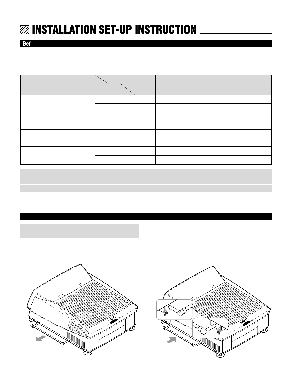
Carrying the Projector
WARNING:
Be sure to use the handles when carrying the projector.
Pulling Out the Handle
Pull out the handle from the bottom side.
Retracting the Handle
Press down the two levers at the same time to retract the
handle.
3
INSTALLATION SET-UP INSTRUCTION
Note on Installation
CAUTION ON INSTALLATION
Position the projector according to the procedures specified in
the following pages. Be sure to maintain the correct projection
distance, direction and angle for optimum performance.
Deviating from the correct installation could degrade the
performance of the projector and may cause reliability
problems.
WARNING:
Static displays that are left on for extended periods may
cause CRT burns that are not covered under warranty.
For screen sizes other than 100", 120", and 180" diagonal,
adjust the CRT angle using the threaded holes. See pages
16 and 18 for detailed procedures.
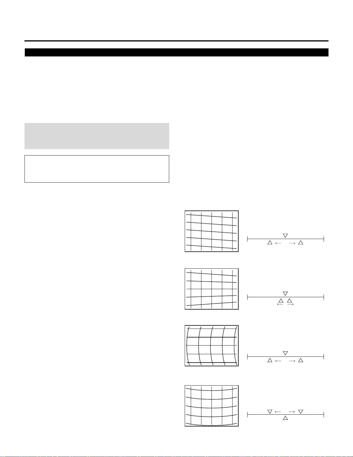
CAUTION ON ALIGNMENT ADJUSTMENT
The adjustment value of the items on the right must be within
the recommended range of the values on the right. If it is hard
or impossible to adjust the items on the right within the
recommended range of values, the most probable cause of this
is incorrect position of the projector. Check for correct
projection distance, direction and angle, and reposition as
recommended in this manual.
Value Recommendation
• TILT
within ±50%
H
V
-100% +100%
• V-KEY
within ±10%
H
V
-100% +100%
• H-BOW
within ±50%
H
• V-BOW
within ±50%
4
V
-100% +100%
H
V
-100% +100%
INSTALLATION SET-UP INSTRUCTION
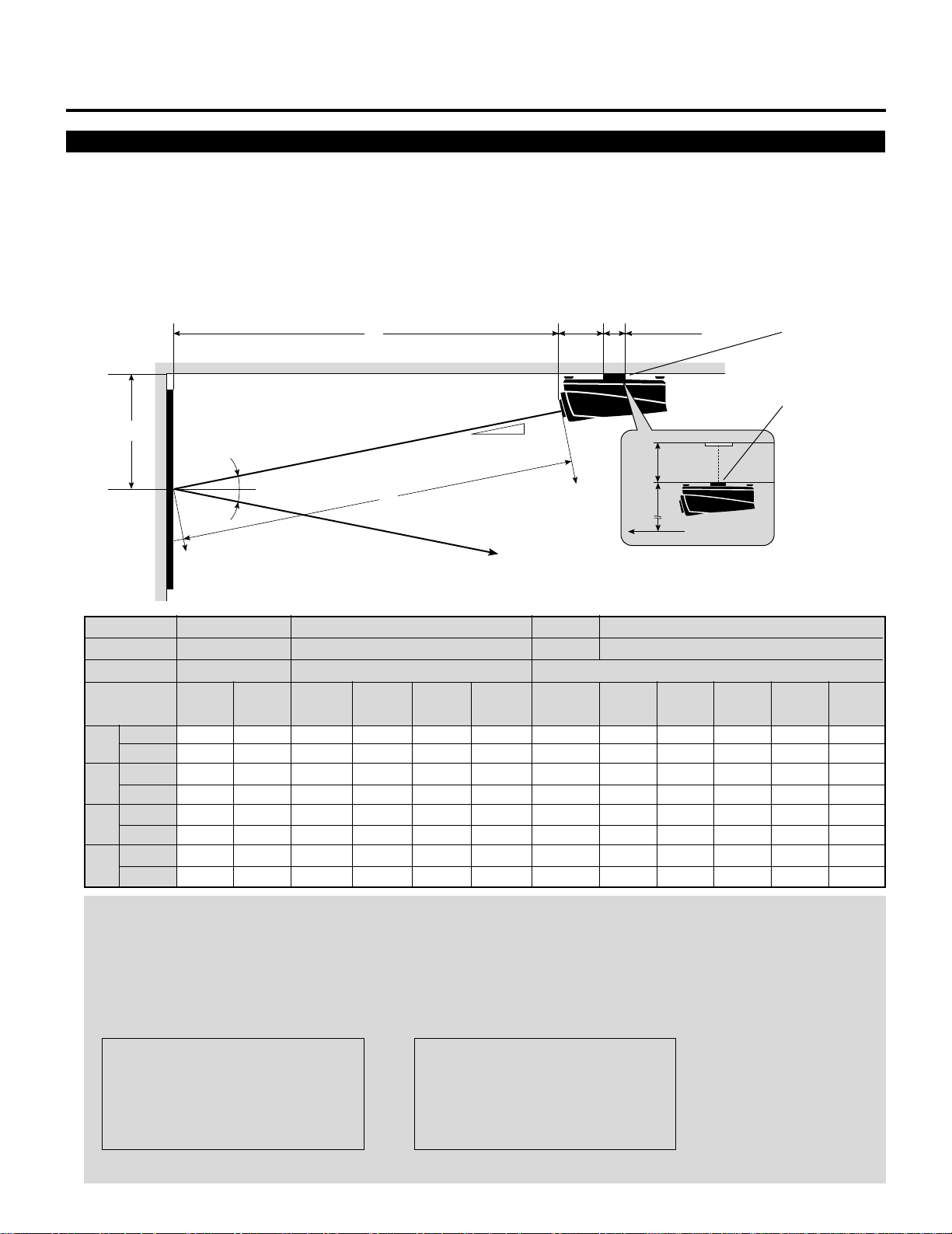
Ceiling Mount Projection Distance and Screen Size for XG85
•
Install in such a way that the projector and screen are positioned in the proper direction and at the proper angle. If not, the projector's
performance will be affected and its reliability will decrease. Be sure to position the projector properly.
The manufacturer will not be held responsible for any problems occurring when the projector is not installed in the proper position.
The following shows the proper relative positions of the projector and screen. Refer to the table to determine the position of
installation
Ceiling Mount System
B
Screen center
α
β (=sinα)
γ (=cosα)
Screen size H-Width
(4:3 Diagonal)
inch
A
mm
inch
B
mm
inch
C
mm
inch
E
mm
48"
(60")
70.28
1785
26.00
661
68.72
1746
–
–
α
α
56"
(70")
81.54
2071
28.36
721
79.73
2025
–
–
64"
(80")
91.6
2318
30.86
784
89.13
2264
–
–
C
A
72"
(90")
101.74
2584
33.11
841
99.36
2524
–
–
80"
(100")
112.68
2862
35.46
901
110.05
2796
–
–
Line of sight
96"
(120")
133.43
3389
39.91
1014
130.32
3310
–
–
α
11.15"
(283mm)
120"
(150")
164.69
4183
47.19
1199
160.72
4083
–
–
5.12"
(130mm)
144"
(180")
196.11
4981
54.38
1381
191.31
4860
–
–
E
B
Screen center
0.9760.9770.978
160"
(200")
214.02
5436
58.31
1481
208.78
5303
1.69
43
12.7°12.6°12.4°12.1°
0.2200.2180.2150.210
192"
(240")
258.51
6566
68.10
1730
252.18
6406
3.91
100
Ceiling Mounting
Ceiling Mounting
When using a screen 150"
(3810mm) or larger (in the
diagonal direction)
216"
(270")
290.48
7378
75.12
1908
283.37
7198
5.88
150
240"
(300")
315.67
8018
80.66
2049
307.95
7822
9.35
238
NOTE:
• For screens 150 inches (3810mm) or larger (in the diagonal direction), set so that the distance between the surface of
installation of the mounting A and the ceiling is E.
• Set the projection distance based on the width of the screen.
• If the figures on the table do not match the figures in the formulae, use the figures on the table.
• For screen sizes of 60 to 300 inches not indicated on the table, use the following proportional formulae:
Units=inches W"=Screen H-Width
A = (25/962W"112.5)24.99`70.28
B = (β2A)`11.26
C = γ2A
E = (1/22Screen Height)1B
Units=mm W"=Screen H-Width
A = (25/962W"112.5)2126.64`1785
B = (β2A)`286
C = γ2A
E = (1/22Screen Height)1B
• The margin of error for projection distance (A) is53%.
5
INSTALLATION SET-UP INSTRUCTION
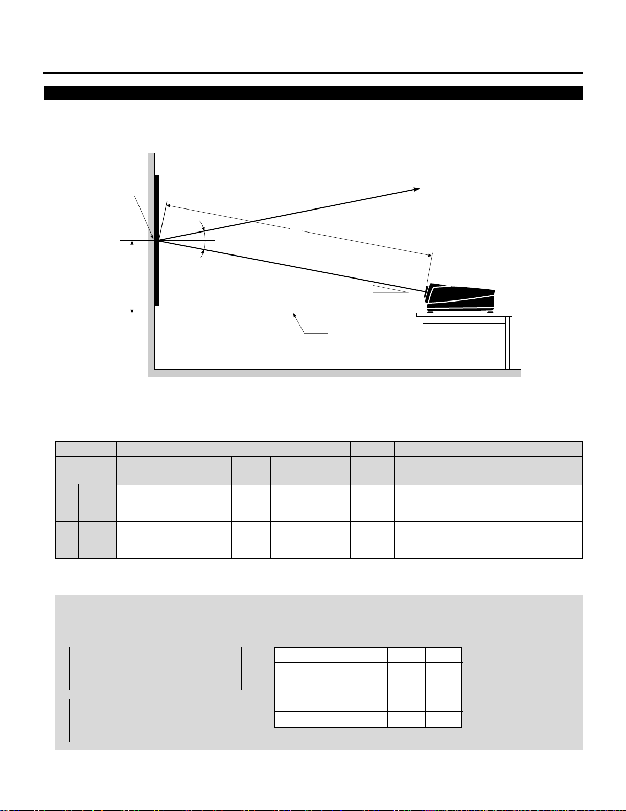
Desk Top Projection Distance and Screen Size for XG85
• The following shows the relative position relationship of the projector with the screen. See table below.
Desk Top System
Screen center
α
Screen size H-Width
(4:3 Diagonal)
α
α
D
12.1° 12.4°
48"
(60")
56"
(70")
64"
(80")
72"
(90")
Line of sight
A
α
Desk top line
A:Distance between the lens and the screen center
D:Distance between the desk top and the screen center
12.6° 12.7°
80"
(100")
96"
(120")
120"
(150")
144"
(180")
160"
(200")
(240")
192"
216"
(270")
240"
(300")
inch
A
mm
inch
D
mm
70.28
1785
24.81
631
81.54
2071
27.17
691
91.26
2318
29.68
754
101.74
2584
31.93
811
112.68
2862
34.28
871
133.43
3389
38.73
984
164.69
4183
46.01
1169
196.11
4981
53.20
1351
214.02
5436
57.13
1451
NOTE:
• The projection distance is based on the screen width.
• Sizes not found between 48 (60) and 240 (300) inches are determined by the following formulae:
Units=inches W"=Screen H-Width
A = (25/962W"112.5)24.99`70.28
D = (β2A)`10.08
Units=mm W"=Screen H-Width
A = (25/962W"112.5)2126.64`1785
Screen size (Diagonal)
60–79"
80–129"
130–179"
180–300"
α
12.1°
12.4°
12.6°
12.7°
β
0.210
0.215
0.218
0.220
D = (β2A)`256
6
258.51
6566
66.91
1700
290.48
7378
73.94
1878
315.67
8018
79.48
2019

INSTALLATION SET-UP INSTRUCTION
Rear Screen Projection Distance and Screen Size for XG85
The following shows the relative position relationship of the projector with the screen. See table below.
Rear Projection System
A
Screen center
Line of sight
α
A:Distance between the lens and the screen center
α
Screen size H-Width
(4:3 Diagonal)
inch
A
mm
70.28
12.1° 12.4°
48"
(60")
1785
56"
(70")
81.54
2071
64"
(80")
91.26
2318
72"
(90")
101.74
2584
80"
(100")
112.68
2862
96"
(120")
133.43
3389
12.6° 12.7°
120"
(150")
164.69
4183
144"
(180")
196.11
4981
NOTE:
• The projection distance is based on the screen width.
• Sizes not found between 48(60)and 240(300)inches are determined by the following formulae:
Units=inches W"=Screen H-Width
A = (25/962W"112.5)24.99`70.28
Units=mm W"=Screen H-Width
A = (25/962W"112.5)2126.64`1785
Screen size (Diagonal)
60–79"
80–129"
130–179"
180–300"
α
12.1°
12.4°
12.6°
12.7°
160"
(200")
214.02
5436
192"
(240")
258.51
6566
216"
(270")
290.48
7378
240"
(300")
315.67
8018
7

INSTALLATION SET-UP INSTRUCTION
Ceiling Mount Projection Distance and Screen Size or XG135LC
•
Install in such a way that the projector and screen are positioned in the proper direction and at the proper angle. If not, the projector's
performance will be affected and its reliability will decrease. Be sure to position the projector properly.
The manufacturer will not be held responsible for any problems occurring when the projector is not installed in the proper position.
The following shows the proper relative positions of the projector and screen. Refer to the table to determine the position of
installation
Ceiling Mount System
B
Screen center
α
β (=sinα)
γ (=cosα)
Screen size H-Width
(4:3 Diagonal)
inch
A
mm
inch
B
mm
inch
C
mm
inch
E
mm
48"
(60")
71.10
1806
25.38
645
69.61
1768
–
–
α
α
56"
(70")
82.83
2104
27.78
705
81.10
2060
–
–
64"
(80")
94.61
2403
30.18
767
92.62
2353
–
–
C
A
72"
(90")
106.34
2701
33.31
846
103.89
2639
–
–
80"
(100")
118.07
2999
35.79
909
115.36
2930
–
–
Line of sight
96"
(120")
140.91
3579
40.61
1032
137.66
3497
–
–
α
11.15"
(283mm)
12.4°
0.215
120"
(150")
175.16
4449
48.45
1231
171.13
4347
–
–
5.12"
(130mm)
144"
(180")
209.57
5323
56.55
1436
204.54
5195
–
–
E
B
Screen center
160"
(200")
232.48
5905
61.55
1563
226.90
5763
–
–
12.6°12.2°11.8°
0.2180.2110.204
0.9760.9770.979
192"
(240")
278.15
7065
71.51
1816
271.47
6895
0.47
12
Ceiling Mounting
Ceiling Mounting
When using a screen 150"
(3810mm) or larger (in the
diagonal direction)
216"
(270")
309.17
7853
78.28
1988
301.75
7665
2.72
69
240"
(300")
338.62
8601
84.70
2151
330.50
8395
5.28
134
NOTE:
• For screens 150 inches (3810mm) or larger (in the diagonal direction), set so that the distance between the surface of
installation of the mounting A and the ceiling is E.
• Set the projection distance based on the width of the screen.
• If the figures on the table do not match the figures in the formulae, use the figures on the table.
• For screen sizes of 60 to 300 inches not indicated on the table, use the following proportional formulae:
Units=inches W"=Screen H-Width
A = (25/962W"112.5)25.47`71.85
B = (β2A)`10.83
C = γ2A
E = (1/22Screen Height)1B
Units=mm W"=Screen H-Width
A = (25/962W"112.5)2141`1825
B = (β2A)`275
C = γ2A
E = (1/22Screen Height)1B
• The margin of error for projection distance (A) is53%.
8

INSTALLATION SET-UP INSTRUCTION
Desk Top Projection Distance and Screen Size for XG135LC
• The following shows the relative position relationship of the projector with the screen. See table below.
Desk Top System
Screen center
α
Screen size H-Width
(4:3 Diagonal)
D
48"
(60")
α
α
11.8° 12.2°
56"
(70")
64"
(80")
72"
(90")
80"
(100")
Line of sight
A
α
Desk top line
A:Distance between the lens and the screen center
D:Distance between the desk top and the screen center
12.4° 12.6°
96"
(120")
120"
(150")
144"
(180")
160"
(200")
192"
(240")
216"
(270")
240"
(300")
inch
A
mm
inch
D
mm
71.10
1806
24.20
615
82.83
2104
26.59
675
94.61
2403
29.00
737
106.34
2701
32.13
816
118.07
2999
34.61
879
140.91
3579
39.43
1002
175.16
4449
47.27
1201
209.57
5323
55.37
1406
232.48
5905
60.37
1533
NOTE:
• The projection distance is based on the screen width.
• Sizes not found between 48 (60) and 240 (300) inches are determined by the following formulae:
Units=inches W"=Screen H-Width
A = (25/962W"112.5)25.47`71.85
D = (β2A)`10.04
Units=mm W"=Screen H-Width
A = (25/962W"112.5)2141`1825
Screen size (Diagonal)
60–89"
90–129"
130–179"
180–300"
α
11.8°
12.2°
12.4°
12.6°
β
0.204
0.211
0.215
0.218
D = (β2A)`245
9
278.15
7065
70.33
1786
309.17
7853
77.10
1958
338.62
8601
83.52
2121

INSTALLATION SET-UP INSTRUCTION
Rear Screen Projection Distance and Screen Size for XG135LC
The following shows the relative position relationship of the projector with the screen. See table below.
Rear Projection System
A
Screen center
Line of sight
α
A:Distance between the lens and the screen center
α
Screen size H-Width
(4:3 Diagonal)
inchmm71.10
A
48"
(60")
1806
11.8° 12.2°
56"
(70")
82.83
2104
64"
(80")
94.61
2403
72"
(90")
106.34
2701
80"
(100")
118.07
2999
96"
(120")
140.91
3579
12.4° 12.6°
120"
(150")
175.16
4449
144"
(180")
209.57
5323
NOTE:
• The projection distance is based on the screen width.
• Sizes not found between 48(60)and 240(300)inches are determined by the following formulae:
Units=inches W"=Screen H-Width
A = (25/962W"112.5)25.47`71.85
Units=mm W"=Screen H-Width
A = (25/962W"112.5)2141`1825
Screen size (Diagonal)
60–89"
90–129"
130–179"
180–300"
α
11.8°
12.2°
12.4°
12.6°
160"
(200")
232.48
5905
192"
(240")
278.15
7065
216"
(270")
309.17
7853
240"
(300")
338.62
8601
10

12345
6
6
6
6
6
12345
12345
12345
12345
PROJECTION CONFIGURATION CHANGE.
Before Installation Change
The projector is electrically and mechanically set for 100 inch diagonal screen, front throw ceiling mount and a projection angle of
12.4˚ (XG85)/12.2˚(XG135LC). If your application is different from the factory setting(for example, ceiling to floor and screen
size between 60 and 300 inch), you will have to reconfigure the projector for your application. Follow the change procedures
according to the instructions below.
For XG85
To change screen size only:
1) Set the focus ring to the proper position. (See pages15 and 16.)
For 100" screen size
R – A-3, B-3
G – A-1, B-3
B – A-3, B-3
For 120" screen size
R – A-3, B-3
G – A-1, B-3
B – A-3, B-3
For 180" screen size
R – A-5, B-5
G – A-1, B-5
B – A-5, B-5
f
2) Adjust the angle of the CRT's. (See page 16.)
To change to the ceiling mount system (rear)
1) Reverse the scan. (See page 14.)
f
2) Set the focus ring to the proper position. (See pages 16 and 17.)
For 100" screen size
R – A-3, B-3
G – A-1, B-3
B – A-3, B-3
For 120" screen size
R – A-3, B-3
G – A-1, B-3
B – A-3, B-3
For 180" screen size
R – A-5, B-5
G – A-1, B-5
B – A-5, B-5
For 100" screen size
Move the CRT to the 100 position
For 120–180" screen size and the
other screen sizes
Move the CRT to the 120, 180, or
60–300 position
To change to the desk top system (front)
1) Reverse the scan. (See page 14.)
f
2) Set the focus ring to the proper position. (See pages 15 and 16.)
For 100" screen size
R – A-3, B-3
G – A-1, B-3
B – A-3, B-3
For 120" screen size
R – A-3, B-3
G – A-1, B-3
B – A-3, B-3
For 180" screen size
R – A-5, B-5
G – A-1, B-5
B – A-5, B-5
f
3) Adjust the angle of the CRT's. (See page 16.)
For 100" screen size
Move the CRT to the 100 position
For 120–180" screen size and the
other screen sizes
Move the CRT to the 120, 180, or
60–300 position
f
4) Select an installation from the PJ ORIENTATION menu in
the SETTING menu. (See “Projection Type Selection” in the
setup manual.)
f
3) Adjust the angle of the CRT's. (See page 17.)
For 100" screen size
Move the CRT to the 100 position
For 120–180" screen size and the
other screen sizes
Move the CRT to the 120, 180, or
60–300 position
f
4) Select an installation from the PJ ORIENTATION menu in
the SETTING menu. (See “Projection Type Selection” in the
setup manual.)
To change to the desk top system (rear, 0 projection angle)
1) Set the focus ring to the proper position. (See pages 16 and 17.)
For 100" screen size
R – A-3, B-3
G – A-1, B-3
B – A-3, B-3
For 120" screen size
R – A-3, B-3
G – A-1, B-3
B – A-3, B-3
For 180" screen size
R – A-5, B-5
G – A-1, B-5
B – A-5, B-5
f
2) Adjust the angle of the CRT's (See page 17.)
For 100" screen size
Move the CRT to the 100 position
For 120–180" screen size and the
other screen sizes
Move the CRT to the 120, 180, or
60–300 position
f
3) Select an installation from the PJ ORIENTATION menu in
the SETTING menu. (See “Projection Type Selection” in the
setup manual.)
11

PROJECTION CONFIGURATION CHANGE
For XG135LC
To change screen size only:
1) Set the focus ring to the proper position. (See page 17.)
For 100" screen size
R – H-3, V-3
G – H-5, V-3
B – H-3, V-3
For 120" screen size
R – H-3.5, V-2.5
G – H-5, V-2.5
B – H-3.5, V-2.5
For 180" screen size
R – H-3.5, V-2.5
G – H-5, V-2.5
B – H-3.5, V-2.5
f
2) Adjust the angle of the CRT's. (See page 18.)
For 100" screen size
Move the CRT to the 100 position
To change to the desk top system (front)
1) Reverse the scan. (See page 14.)
For 120–180" screen size and the
other screen sizes
Move the CRT to the 120, 180, or
60–300 position
To change to the ceiling mount system (rear)
1) Reverse the scan. (See page 14.)
f
2) Set the focus ring to the proper position. (See page 17.)
For 100" screen size
R – H-3, V-3
G – H-5, V-3
B – H-3, V-3
For 120" screen size
R – H-3.5, V-2.5
G – H-5, V-2.5
B – H-3.5, V-2.5
For 180" screen size
R – H-3.5, V-2.5
G – H-5, V-2.5
B – H-3.5, V-2.5
f
3) Adjust the angle of the CRT's. (See page 18.)
For 100" screen size
Move the CRT to the 100 position
For 120–180" screen size
Move the CRT to the 120, or 180.
f
4) Select an installation from the PJ ORIENTATION menu in
the SETTING menu. (See “Projection Type Selection” in the
setup manual.)
f
2) Set the focus ring to the proper position. (See page 17.)
For 100" screen size
R – H-3, V-3
G – H-5, V-3
B – H-3, V-3
For 120" screen size
R – H-3.5, V-2.5
G – H-5, V-2.5
B – H-3.5, V-2.5
For 180" screen size
R – H-3.5, V-2.5
G – H-5, V-2.5
B – H-3.5, V-2.5
f
3) Adjust the angle of the CRT's. (See page 18.)
For 100" screen size
Move the CRT to the 100 position
For 120–180" screen size and the
other screen sizes
Move the CRT to the 120, 180, or
60–300 position
f
4) Select an installation from the PJ ORIENTATION menu in
the SETTING menu. (See “Projection Type Selection” in the
setup manual.)
To change to the desk top system (rear, 0 projection angle)
1) Set the focus ring to the proper position. (See page 17.)
For 100" screen size
R – H-3, V-1
G – H-5, V-1
B – H-3, V-1
For 120" screen size
R – H-3.5, V-1
G – H-5, V-1
B – H-3.5, V-1
For 180" screen size
R – H-3.5, V-1
G – H-5, V-1
B – H-3.5, V-1
f
2) Adjust the angle of the CRT's (See page 18.)
For 100" screen size
Move the CRT to the 100 position
For 120–180" screen size and the
other screen sizes
Move the CRT to the 120, 180, or
60–300 position
f
3) Select an installation from the PJ ORIENTATION menu in
the SETTING menu. (See “Projection Type Selection” in the
setup manual.)
12

Removing and Reinstalling Top Cover
CAUTION:
• Be sure to turn off the projector and unplug the power cord before
opening the top cover.
PROJECTION CONFIGURATION CHANGE
To remove the top cover:
1 Loosen four screws A.
• These are retaining screws.
• There are two lids on the top cover. Open the lid to access the
two screws each.
• The other two screws hold the front panel.
2 Slide and open the top cover in the direction of the arrow.
Screws A
3 To reinstall it, aligning the catches with the hole and slide the top
cover in the direction of the arrow.
4 Tighten the two A screws.
13

PROJECTION CONFIGURATION CHANGE
Scan Reversal
You will have to reverse the horizontal polarity when changing the projector’s configuration.
NOTE: For vertical polarity , scan reversal can be changed using the PROJECTION feature in the SETTING MODE menu.
To reverse the scan, proceed as follows:
CAUTION: Always disconnect the projector from the AC source before reversing the plug. Failure to observe this precaution may
result in electric shock or damage to the projector.
1 Remove the top cover.
• See Removing and reinstalling Top Cover section.
2 Reverse the horizontal scan.
• To reverse the scan there are three plugs on the sweep board. EB, EG and ER are the horizontal connectors.
First remove the dummy plug.
Secondly remove the plug and turn it 180 degrees, then reinstall. Do this for all three of horizontal connectors depending upon
your application (See Table below). Third, install the dummy plug on the opposite side.
Horizontal polarity
Desk top, front / Ceiling, rear
EB ER
Red
Blue
Dummy
plug
Desk top, rear / Ceiling, front
EB EGEG
Red
ER
Dummy
plug
Blue
Red
Blue
14

PROJECTION CONFIGURATION CHANGE
Removing and Reinstalling Front Panel
The projector can project an image from 60 to 300 inches diagonal. From the factory the projector is set for ceiling mount, 100 inch
diagonal screen size and a projection angle of 12.4 degrees. The projector can be used in three other degree applications.
Before the following procedures, remove the front panel by loosening the two screws B which hold the front panel. There are two
screws on each side.
Screws B
g
• Reverse the preceding steps to reinstall the front panel.
Screen Size Change(Adjusting Focus Rings and CRT Angle) for XG85
• Adjusting Focus Rings for the XG85
There are three sets of adjusting focus rings, two between each CRT and lens.
These focus rings are used for maintaining optimum edge focus for the various screen sizes and projection angles.
*When setting the focus rings or changing CRT angle, you must first remove the front panel.
1 Loosen the four screws at the lens.
CAUTION: Be careful not to remove any of the four screws
completely. The falling lens can cause serious injury especially
when the projector is installed on the ceiling.
Screws
Screws
15

PROJECTION CONFIGURATION CHANGE
2Rotate and set the knobs (A and B) to the
right position. The table below lists which
position the knob should be set to for any
given screen size and angle. The similar
table is also on the back of the front panel.
knob A
knob B
A
1 2 3 4 5
B
Rotate
60-300
100
180120
60-300
180 120
100
3 Tighten the four screws at the lens.
Position of Knobs for the XG85
Projection angle
and screen size (Diagonal)
12.1°
12.4°(Factory preset)
12.6°
12.7°
0°
• Adjusting Angle of CRTs for the XG85
To adjust the angle of the CRTs, remove screws E and loosen screws
C and D.
Now you can move the tube and lens assembly to one of the three
other positions. Then replace screws E and tighten screws C and D.
This process needs to be done for the red and blue CRTs. The green
CRT is never repositioned. Use the table below to select the proper
setting for your screen size.
60" – 79"
80" – 129"
130" – 179"
180" – 300"
60" – 79"
80" – 129"
130" – 179"
180" – 300"
ED DE
F
100
60-300
CRT
R
Knob
G
Knob
ABABAB
2
1
2
2
3
1
3
3
4
1
4
4
5
1
5
5
1
1
1
2
1
1
1
3
1
1
1
4
1
1
1
5
180120
B
Knob
2
3
4
5
2
3
4
5
100
180 120
2
3
4
5
1
1
1
1
F
60-300
NOTE: The threaded hole marked “60-300” F is drilled lengthwise so
you can move the CRT assembly to any screen size. Adjust the red
and blue lens so that the red or blue beam is aligned with the green
beam. After doing this, adjust the lens focus (see the next page).
Then tighten the screws E.
Metal impression stamp screen size
Range of screen size (diagonal)
60-300
60"-300"
100
100"
16
120
120"
CC
180
180"

PROJECTION CONFIGURATION CHANGE
Screen Size Change(Adjusting Focus Rings and CRT Angle) for XG135LC
• Adjusting Focus Rings for the XG135LC
There are three sets of adjusting focus rings, two between each CRT and lens.
These focus rings are used for maintaining optimum edge focus for the various screen sizes and projection angles.
*When setting the focus rings or changing CRT angle, you must first remove the front panel.
1 Loosen the four screws.
2 Rotate and set the knobs (H and V) to the
right position. The table below lists which
position the knob should be set to for any
given screen size and angle. The similar
table is also on the back of the front panel.
knob H
54321 54321
H V
Rotate
Screws
Screws
knob V
54321 54321
5
4
3
2
1
5
4
3
2
1
H V
H V
1
2
3
4
5
1
2
3
H V
54
3 Tighten the four screws.
Position of Knobs for the XG135LC
R
Knob
HV
1
2
3
3.5
3.5
3.5
4
1
2
3
3.5
4
Projection angle
and screen size (Diagonal)
11.8°
12.2°
(Factory preset)
12.4°
12.6°
0°
17
CRT
60" – 69"
70" – 89"
90" – 109"
110" – 129"
130" – 169"
170" – 209"
210" – 300"
60" – 69"
70" – 89"
90" – 109"
110" – 209"
210" –300"
2.5
2.5
2.5
G
Knob
HVHV
5
5
5
4
5
4
3
5
3
2.5
5
2.5
5
2.5
5
2
5
2
1
5
1
1
5
1
1
5
1
1
5
1
1
5
1
3.5
3.5
3.5
3.5
1
2
3
4
1
2
3
4
B
Knob
5
4
3
2.5
2.5
2.5
2
1
1
1
1
1

PROJECTION CONFIGURATION CHANGE
• Adjusting Angle of CRTs for the XG135LC
To adjust the angle of the CRTs, remove screws E and loosen screws
C and D.
Now you can move the tube and lens assembly to one of the three
other positions. Then replace screws E and tighten screws C and D.
This process needs to be done for the red and blue CRTs. The green
CRT is never repositioned. Use the table below to select the proper
setting for your screen size.
NOTE: The threaded hole F is drilled lengthwise so you can move the
CRT assembly to any screen size. Adjust the red and blue lens so that
the red or blue beam is aligned with the green beam. After doing this,
adjust the lens focus (see the next page).
Then tighten the screws E.
FFDD
54321 54321
5
4
3
2
1
5
4
3
2
1
H V
H V
1
2
3
4
5
1
2
3
H V
4
5
EC CE
Metal impression stamp screen size
Range of screen size (diagonal)
60-300
60"-300"
100
100"
120
120"
180
180"
18

Lens Focus Adjustment
Adjust the center focus and edge focus mechanically to
obtain the best screen focus.
NOTE:
• Plug the power cord and turn on the projector before adjustment.
• The lens focus adjustment must be performed for each lens.
• Select the FOCUS test pattern using the TEST button on the full
function remote control.
Proceed as follows:
PROJECTION CONFIGURATION CHANGE
1 Press the R, G, or B button on the full function remote control to
project the CRT beam to be adjusted.
• You can turn on or off each CRT beam(R, G and B)separately.
2 Adjust the center focus.
• Loosen the wing nut A. Rotate the lens using the wing nut A
until the center of the screen is in focus.
When you get the best center focus, tighten the wing nut A.
NOTE: Do not over-tighten the wing nut.
3 Adjust the edge focus.
• Loosen the wing nut B. Rotate the lens barrel until the edge area
of the screen is focused. Tighten the wing nut B.
4 Recheck center focus.
• If it is out of focus, repeat steps 2 and 3.
5 Repeat steps 1 to 4 for the other CRTs.
6 Reinstall the front panel.
Wingnut B
Wingnut A
B
EDGE Focus
A
CENTER
Focus
19

NEC Corporation
Printed in Japan
78409141
 Loading...