


MultiSync XG85
MultiSync XG135LC
Large Screen MultiSync Projection Monitor
Set-Up Manual
Model Number:
XG-852/XG-1352
XG-852G/XG-1352G
1

2

12345
6
6
6
6
6
12345
12345
12345
12345
CONTENTS.
PART NAMES AND FUNCTIONS ......................................... 4
Front Terminal Panel ...................................................................4
Rear Control Panel ......................................................................4
Optional Boards...........................................................................6
Remote Control Unit....................................................................8
Battery installation and replacement ...................................11
Remote control cautions.....................................................11
Handling remote control and batteries ................................11
Set-Up (for service personnel)
BEFORE SET-UP ......................................................... 14
Displaying the Menu and Adjustment Screens ..........................14
Storing Projector Settings (Automatic Save Feature) ................15
On ADJUST MODE ....................................................................17
Test Pattern...............................................................................18
SIGNAL ENTRY............................................................19
Signal Entry Procedures ............................................................19
Checking and Setting Various Parameters ................................30
ADJUSTMENT .............................................................38
Set-Up Procedure......................................................................38
Electrical Focus Adjustment ......................................................39
Alignment Adjustment...............................................................43
Static Convergence Adjustment ................................................50
Dynamic Convergence Adjustment............................................51
Color Temperature and White Balance Adjustment ...................59
R, G, and B Gain Adjustment.....................................................60
PASSCODE................................................................ 61
Entering Passcode.....................................................................61
Registering Passcode................................................................62
Changing Your Passcode ..........................................................64
Canceling Your Passcode..........................................................66
SETTING .................................................................. 68
Displaying the Various Setting Features ....................................68
Projection Type Selection..........................................................69
Connecting to the Switcher .......................................................71
Default Input Selection ..............................................................73
Focus Edge Mode...................................................................... 76
S-Video Mode Selection ............................................................78
Video Mode Selection................................................................80
Auto Power ON Mode Setting....................................................82
Warm-Up Mode Setting ............................................................84
Automatic Save Feature.............................................................86
Phosphor Saver Setting ............................................................88
Signal Switching Mute Mode Setting ........................................90
Direct Entry Access Setting .......................................................92
Blue Focus Tracking Setting......................................................94
Optional Terminal Baud Rate Selection .....................................95
RGB/COMPONENT Search Setting ............................................ 96
On-Screen Display Mode Setting...............................................98
On-Screen Display Color Setting .............................................100
Date, Time Display Setting ...................................................... 102
Entering Date and Time ...........................................................104
PJ Address Display Setting .....................................................106
"NEW SIGNAL" Message Display Setting .................................107
Auto Sequence Setting ............................................................108
Address Setting.......................................................................117
Projector Version Number.......................................................120
Checking and Setting the Running Time .................................121
Viewing Default Data ..............................................................122
REFERENCE ADJUSTMENT............................................ 123
REF. ADJUST menu.................................................................123
ASTIG Adjustment...................................................................124
Bright Uniformity Adjustment..................................................126
White Uniformity Adjustment ..................................................127
Raster Centering Adjustment ..................................................128
Appendix
TIMING CHARTS ........................................................ 130
Pre-set Signals........................................................................130
Input Signal Reference Chart...................................................131
Input Signal Timing .................................................................132
MESSAGE LIST.......................................................... 133
3
12345
6
6
6
6
12345
12345
12345
PART NAMES AND FUNCTIONS
PART NAMES AND FUNCTIONS.
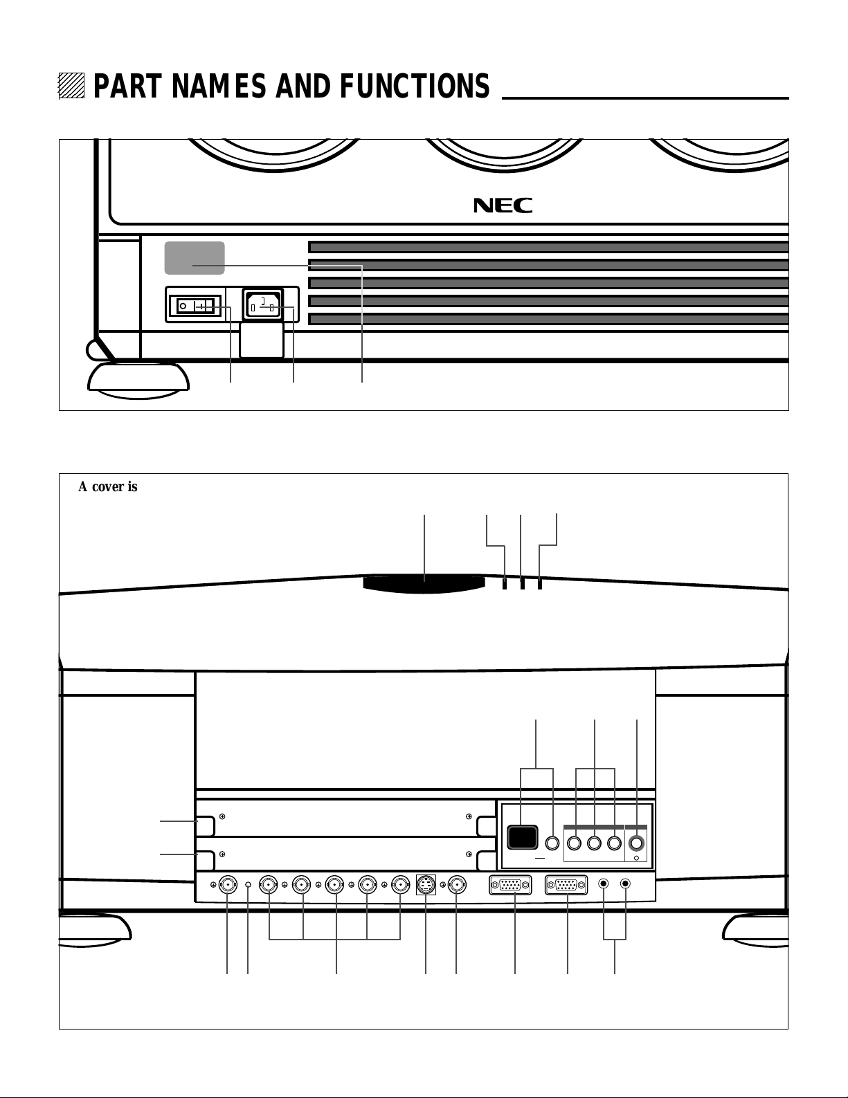
Front Terminal Panel
1 32
Rear Control Panel
A cover is provided to attach the rear control panel.
I
H
4 65 7
89
INPUT SELECT POWER
INPUT SELECT ENTERON/OFFINDICATOR
0
I
ACAT OUT R/Cr G/Y B/Cb H/HV V S-VIDEO VIDEO OPTION REMOTE1 REMOTE2
J
A
4
OUT IN
GFEDCB

PART NAMES AND FUNCTIONS
Front Panel
1 Power Switch (Main power)
To turn on the main power to the projector press the
switch to the ON position (I). The STANDBY and the RC
READY indicator will light.
In this condition you can start up the projector by pressing
the POWER ON button on the remote control or the
POWER button on the rear panel.
Press to the OFF position (0) to turn the main power off.
NOTE: When turning off the main power,first return the
projector to the standby condition by pressing the
POWER OFF button on the remote control or the POWER
button on the rear panel and thin turn off the main
POWER switch.These procedures are necessary to
protect your projector and the connected equipment.
2 AC INPUT
Connect the supplied power cord here.
3 Remote Sensor
Receives the signal from the supplied remote control
when used in the wireless condition.
Rear Panel
4 Remote Sensor
Receives the signal from the supplied remote control
when used in the wireless condition.
5 POWER Indicator
Lights up when the projector is turned on.
6 STANDBY Indicator
Lights up when the projector’s main POWER swicth is on
Flashes when the projector is not connected with the
Switcher correctly or when the Switcher is turned off.
7 RC READY Indicator
Lights up when the projector's main POWER switch is on.
Flashes when the projector receives a signal from the
remate control.
8 Two Digit Display
INDICATOR:
Displays projector error codes.(“00” in normal operation)
ON/OFF Switch:
Turns the INDICATOR on or off.
9 INPUT SELECT Buttons
INPUT: press to display the INPUT SELECT screen.
SELECT: press to select an input by highlighting the
input terminal.
ENTER: press to execute selection and to switch input.
0 POWER Button
Turns the projector on or off when the projector is in the
standby condition (Main Power switch must be on and the
STANDBY and the RC READY indicator lit).
A ACAT OUT Terminal
This is a video output connector for the optional built in
CCD camera. The CCD camera is needed in order to
perform automatic convergence with the optional ACAT
software.
B
R/Cr, G/Y, B/Cb H/V and V Input Terminals (INPUT A)
Connect R,G,B,H (Horizontal sync) and V (Vertical sync)
outputs of the external equipment (such as the Switcher).
If using a component with a combined sync (SYNC)
output,connect it to the H/V terminal. When using
luminance and color-difference signals of HDTV and
DVD, connect a Pr/Cr to the R, a Y to the G and a Pb/Cb
to the B input of the projector.
C S-VIDEO Input Terminal
(INPUT A)
Connect to the S-video output of the external equipment
such as a VCR with an S-video output.This terminal
allows switching between S2 and S1 VIDEO input modes.
D VIDEO Input Terminal
(INPUT A)
Connect to the video output of the external equipment
such as a VCR or laser disk player.
E OPTION Terminal
For system expansion such as PC-control.
F REMOTE 1 Terminal
This terminal allows external control of the projector from
either the Switcher or from an external control.When the
Switcher is used,connect to the REMOTE 1 terminal on
the back of the Switcher.
NOTE: The ISS-6020/ISS-6020G Switcher is compatible
.
with this projector.
G REMOTE 2 Terminal
IN: for the supplied service remote control.
OUT: connect to a second projector’s IN terminal to relay
the input at the IN terminal.
NOTE: The wireless control does not work when the plug
of the supplied remote cable is inserted into the REMOTE 2 IN terminal.
H INPUT B
Slot for adding optional RGB or video input cards.
I INPUT C
Slot for adding optional RGB or video input cards.
NOTE: The optional RGB INPUT and VIDEO INPUT
modules can be installed in the INPUT B and INPUT C
slots.
J Active Indicator (green LED)
Lights up when the INPUT A slot is selected.
5

PART NAMES AND FUNCTIONS
OPTIONAL Boards
VIDEO INPUT Board [XG VIDIN (A)]
Front view
LRLR
VIDEO INPUT
1 Active Indicator (green LED) ...... Lights up when this board is selected.
2 VIDEO INPUT Terminal ............... Connects composite video output signals.
3 S-VIDEO INPUT Terminal ........... Connects S-video output signals.
4 VIDEO INPUT Terminal ............... Connect to the audio outputs of the external equipment such as a VCR.
5 S-VIDEO INPUT Terminal ........... Connect to the S-video audio outputs of the external equipment such as a VCR
RGB INPUT Board [XG RGBIN (A)]
Front view
RGB INPUT
R G B H/HV V
1 23
1 Active Indicator (green LED) ...... Lights up when this board is selected.
2 R Input Terminal.......................... Connects an Red output signal.
3 G Input Terminal ......................... Connects a Green output signal.
4 B Input Terminal.......................... Connects a Blue output signal.
5 H/HV Input Terminal.................... Connects horizontal sync or horizontal/vertical sync output signals.
6 V Input Terminal .......................... Connects a vertical sync output signal.
7 AUDIO Input Terminals............... Connect to the audio outputs of the external equipment such as ISS-6020/6020G.
VIDEO
S-VIDEO
312
AUDIO INPUT
4
S-VIDEOVIDEO
5
(Not available on this model.)
with S-video outputs. (Not available on this model.)
45
6
(Not available on this model.)
LR
AUDIO INPUT
7
RGB INPUT Board
Top view
8 Rotary Switch (S1001)
9 Jumper(S1002, S1003, S1004)
9
8
6
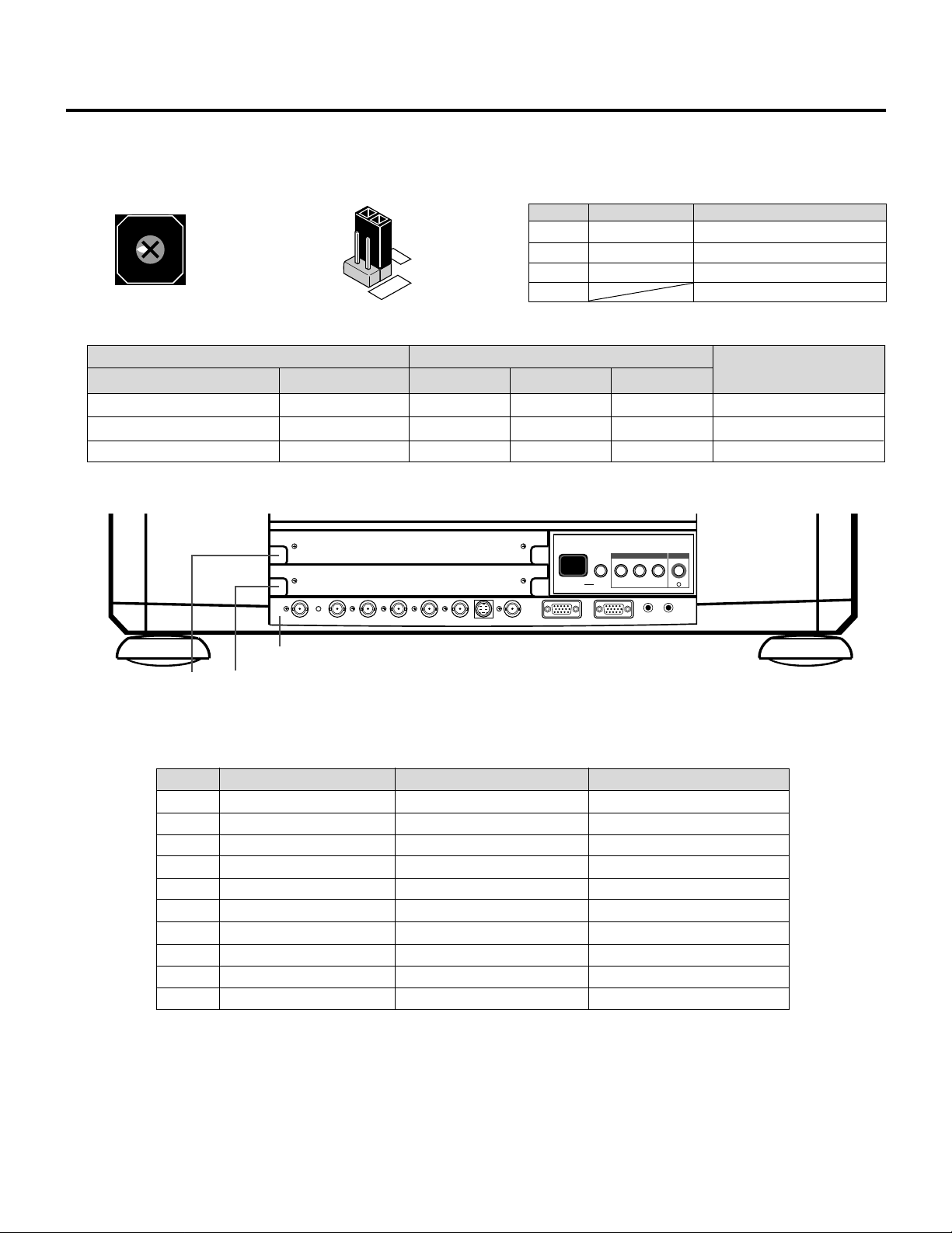
PART NAMES AND FUNCTIONS
The combination of the rotary switch and the jumper pins allows the projector to accept VIDEO or COMPONENT signals. Note that
this board cannot accept RGB signals when board is set to VIDEO input.
Rotary switch (S1001)
5
6
4
7
3
8
2
9
1
0
Jumper (S1002, S1003, S1004)
Setting of Rotary switch and Jumpers
Rotary Switch(S1001)
0
1
*
3
* indicates factory preset.
SLOT FOR OPTIONAL MODULE
Setting of Rotary switch
No.
0
RGB
4
2
3
VIDEO
1
3
2, 4-9
Mark
VIDEO
OPTION
RGB
Table for Setting Rotary Switch and Jumpers.
Input Signal
Jumpers
(2, 3) Short
(2, 3) Short
(1, 2) Short
ACAT OUT R/Cr G/Y B/Cb H/HV V S-VIDEO VIDEO OPTION REMOTE1 REMOTE2
R terminal
VIDEO
Pr/Cr
R
G terminal
Y
Y
G
B terminal
Pb/Cb
INPUT SELECT POWER
INPUT SELECT ENTERON/OFFINDICATOR
OUT IN
VIDEO input
COMPONENT INPUT
RGB input
Not used
* No.3 is factory preset.
Board Identification
C
COMPONENT
B
I
Input
*
VIDEO
RGB
INPUT A slot
INPUT B slotINPUT C slot
Corresponding slot number
You can also select the input signal directly by pressing the INPUT “1” through “10” button. In this case INPUT buttons function as
follows:
INPUT A slot
*1
1
2
3
4
5
RGB
VIDEO
S-VIDEO
*2
*3
INPUT B slot
RGB/COMPONENT/VIDEO
S-VIDEO
INPUT C slot
6
*2
7
*3
8
RGB/COMPONENT/VIDEO
S-VIDEO
9
10
COMPONENT
*1 Some settings allow you to retrieve a COMPONENT signal automatically. See “RGB/COMPONENT Search Setting”.
*2 When the optional RGB input board is installed and the RGB input is set, an RGB signal will be selected; when the RGB input
board is installed and the COMPONENT input is set, a COMPONENT signal will be selected; when the optional RGB input
board is installed and the VIDEO input is set, a VIDEO signal will be selected.
When the optional VIDEO input board is installed, a VIDEO signal will be selected.
*3 An S-VIDEO signal will be selected when :
1. the optional RGB input board is installed and the VIDEO input is set.
2. the optional VIDEO input board is installed.
7
PART NAMES AND FUNCTIONS
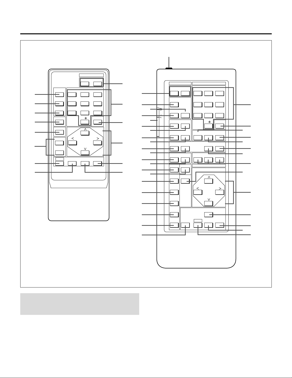
Remote control unit
4
OPERATE
8
1 ABC 2 DEF 3 GHI
PICTURE
4 JKL 5 MNO 6 PQR
MUTE
SOUND
7 STU 8 VWX 9 YZ /
MUTE
9
0
DISPLAY
B
STATIC
R
Q
B
NORMAL ENTER
W
User Remote Control
RC-6320
POWER
ON OFF
10 ,.
CAPTION
X
1
POWER INPUT
1 ABC 2 DEF 3 GHIOFFON
1
ADJUST
SOUND MUTE
PHASETILT
4 JKL 5 MNO 6 PQRTEST
7 STU 8 VWX 9 YZ/
10 ,.
CAPTION
HELP INFO
RGBPOINTSTATIC
POSITION
CURSOR
INPUT LIST
KELVINFOCUS
K
Y
L
M
N
O
P
Q
Z
K
2
Y
3
4
5
ON
OFF
OPERATE
PIC FUNC
SOUND FUNC
6
7
PIC MUTE
8
R
9
DISPLAY
0
A
ENDCTL
U
VS
B
D
C
J
BOW
ADDRESS
E
AMPLIT
F
LINEAR
R
G
H
I
KEYSTN
PINCUS
NORMAL
STORE
T
CTL ENTER END
U
V
S
W
NOTE: The full function remote control is designed for setup
adjustment. Use the user remote control for normal
operation.
Full Function Remote Control
RC-6321
1POWER Buttons (ON/OFF)
Press the ON button to turn the projector on when the
projector is in the standby condition (STANDBY and RC
READY indicators lit). Press the OFF button to return the
projector to the standby condition.
2TEST Button
Press to display the “TEST PATTERN” menu from which
you can select a test pattern.
8

PART NAMES AND FUNCTIONS
3ADJUST Button
Press to display the “ADJUST” menu.
4OPERATE Button
Press to display the “OPERATE” menu.
5Backlight Switch
Turns the backlight on and off.
If no button operation is made within 30 seconds with
the Backlight ON, the Backlight will turn off to
conserve battery life.
6PIC FUNC Button
Press to display the picture adjustment screen.
NOTE: Some function items will not be available
depending on the type of video signal.
7SOUND FUNC Button
Press to display the VOLUME adjustment screen. You
can adjust the volume of the ISS-6020/ISS-6020G
Switcher.
NOTE: Even if the on-screen display may be turned off
with pressing CTL and DISPLAY, any adjustment will
still change the projector’s memory settings. This mode
is available even when an input is switched to another or
the power is turned off using the POWER OFF button on
the remote control.
AFOCUS Button
Press to enter the FOCUS mode.Pressing with CTL will
bring you to the ASTIG adjustment screen.
BSTATIC Button
Press to enter the STATIC mode. You can adjust the static
convergence.
CPOINT Button
Press to enter the POINT mode. You can adjust the point
convergence.
DTILT Button
Press to enter the TILT, SKEW mode. You can adjust the
tilt and the skew of the projected image.
8PICTURE (PIC) MUTE Button
Press to mute the picture. Press again to display the
picture. You can also mute the picture by holding
down CTL and pressing PICTURE MUTE buttons. To
restore the picture, holding down CTL and press
PICTURE MUTE again. Or simply press END.
NOTE: When the picture is muted by using CTL and
PICTURE MUTE buttons, even if an input is
switched to another or the power is turned off using
the remote POWER OFF button, the mute cannot be
canceled.
9SOUND MUTE Button
Press to mute the sound. Press again to return the
sound.
NOTE: This works only with the ISS-6020/ISS-6020G
Switcher.
0DISPLAY Button
Press to turn on or off the on-screen display. Pressing
with CTL eliminates the on-screen display; pressing
with CTL will restore display.
EBOW Button
Press to enter the BOW mode. You can adjust the horizontal and the vertical bow of the projected image.
Pressing with CTL will bring you to the LINE DISTORTION adjustment screen.
FAMPLIT Button
Press to enter the AMPLITUDE mode. You can adjust the
horizontal width and the vertical height of the projected
image.
GLINEAR Button
Press to enter the LINEARITY mode. You can adjust the
horizontal and the vertical linearity of the projected image.
Pressing with CTL will bring you to the LINEARITYBALANCE adjustment screen.
HKEYSTN Button
Press to enter the KEYSTONE mode. You can adjust the
horizontal and the vertical keystone of the projected
image. Pressing with CTL button will bring you to the
KEY-BALANCE alignment screen.
9

PART NAMES AND FUNCTIONS
IPINCUS Button
Press to enter the PINCUSHION mode. You can adjust
the horizontal and the vertical pincushion of the projected
image. Pressing with the CTL button will bring you to the
PIN-BALANCE alignment screen.
JPHASE Button
For service personnel only.
KINPUT Button
Selects menus and switches input signals.
LHELP Button
Press to display the explanation of the current selected
function and available functions.
MINPUT LIST Button
Press to display the memory list of the recorded input
signals.
NINFO Button
Press to display the various parameters and settings of the
currently displayed image. Pressing with the CTL button
displays some of items available in SETTING MODE.
OKELVIN Button
Press to enter the KELVIN mode. You can adjust the
color temperature and, the white and the black level.
PPOSITION Button
Press to enter the position mode. You can adjust the
horizontal, vertical position and horizontal, vertical
blanking and image size.
QR, G, and B Buttons
Turn each CRT beam on and off separately. When using
with the CTL button, you can select the CRT to be
adjusted during convergence and focus adjustments. Note
that the G button is only on the full function remote
control.
SNORMAL Button
Returns the standard level for each signal. When pressed
once, the confirmation message will be displayed. When
“YES” is selected and ENTER is pressed, the data will be
returned to the standard level. While holding down the
CTL button, press the NORMAL button to display the
“LOAD/CANCEL” menu to select either LOAD (last
stored level) or CANCEL (data cancelled).
TSTORE Button
Memorizes the adjustments setting of each signal separately.
When pressed once, the confirmation message “STORE?”
will be displayed. When selecting “YES” and ENTER, the
data will be stored in memory.
UEND Button
Ends the adjustment mode.
VENTER Button
Executes menu selection and switches to selected input.
WCTL Button
Used in conjunction with other buttons, similar to a shift
key on a computer.
XRemote Control Jack
Insert the plug of the supplied remote cable here when the
full function remote control is used in the wired condition.
YCAPTION Button
Press to display the CLOSED CAPTION menu.
ZADDRESS Button
Press to display the ADDRESS menu. Pressing with CTL
allows you to specify the address for the remote control.
RCURSOR Buttons
Used for increasing and decreasing control levels, cursor
movement and convergence adjustments.
10
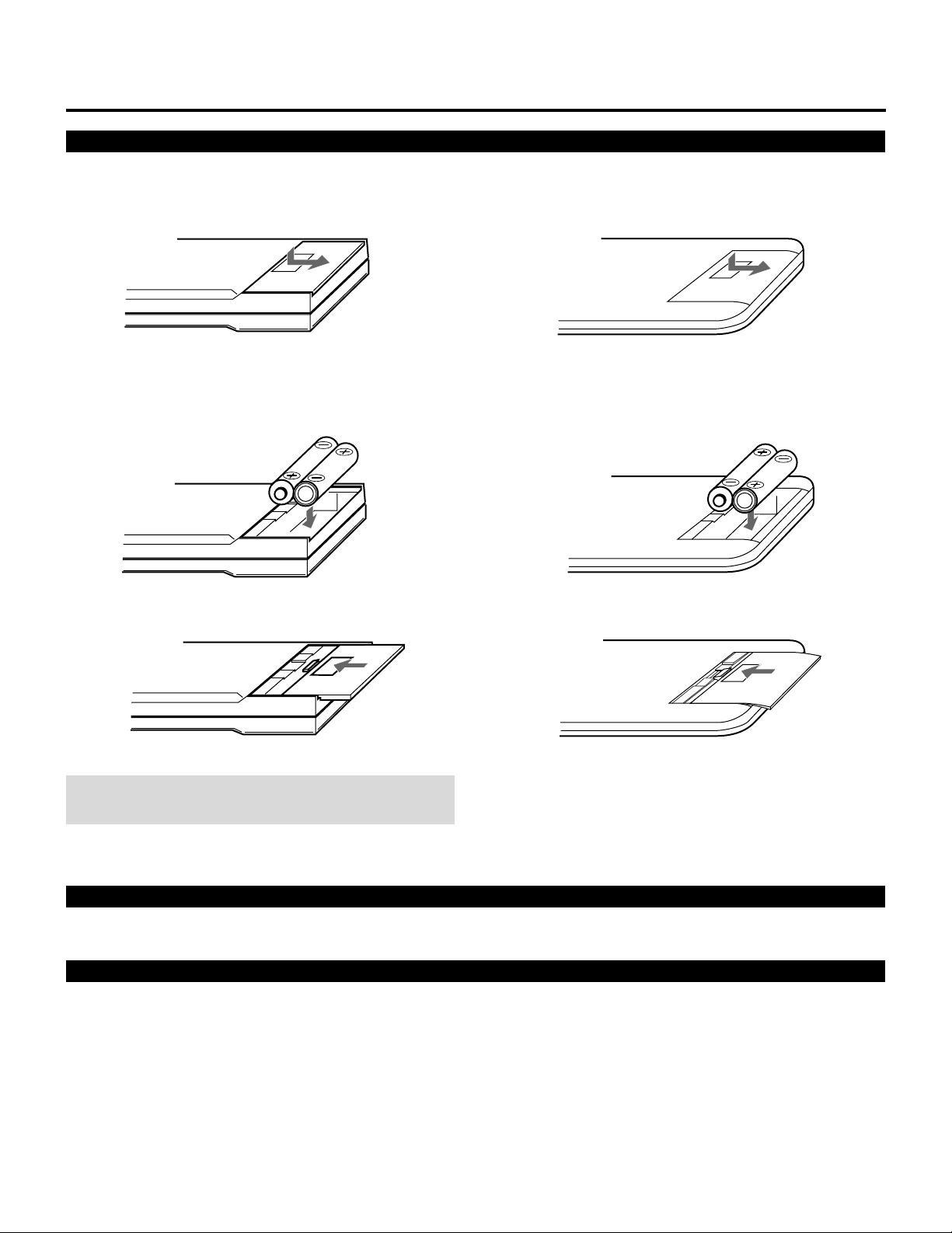
Battery installation and replacement
PART NAMES AND FUNCTIONS
User remote control (RC-6320)
Press down on the battery compartment cover and slide
1
the cover in the direction of the arrow.
2 Install the two new batteries, making sure that their
polarity matches the , . diagrams inside the battery
compartment. Incorrect polarity could damage the unit.
Full function remote control (RC-6321)
Press down on the battery compartment cover and slide
1
the cover in the direction of the arrow.
2 Install the two new batteries, making sure that their
polarity matches the , . diagrams inside the battery
compartment. Incorrect polarity could damage the unit.
3 Close the battery compartment cover.3 Close the battery compartment cover.
NOTE: The remote control is powered by two alkaline 1.5V
AA batteries.
Remote control cautions
Use the remote control within a distance of about 7m (23 ft.) and at 30 degrees angle left and right.
Handling remote control and batteries
• Do not drop or mishandle the remote.
• Do not get the remote wet. If the remote gets wet, wipe it dry immediately.
• Avoid heat and humidity.
• When not using the remote for a long period, remove the batteries.
• Do not use new and old batteries together, or use different types together.
• Do not take apart the batteries, heat them, or throw them into a fire.
• Avoid using the full function remote control as wireless with the backlight switch ON for an extended period of time. This can
cause short battery life.
11

12

Set-Up
(for service personnel)
Set-Up
The Signal Entry chapter explains how to register a new
input signal and how to set various parameters of the
currently selected signal.
The Adjustment chapter gives you the procedures for
various adjustment such as focus, alignment, convergence. This chapter also explains the passcode. It is a
convenient way to prevent any tampering of projector
set-up information by unauthorized individuals.
The Setting chapter gives you details on setting for
various use.
CONTENTS
Before Set-Up ................................................14
Signal Entry....................................................19
Adjustment .....................................................38
Passcode .......................................................61
Setting............................................................68
Reference Adjustment .................................123
13
12345
6
6
6
6
6
12345
12345
12345
12345
BEFORE SET-UP.
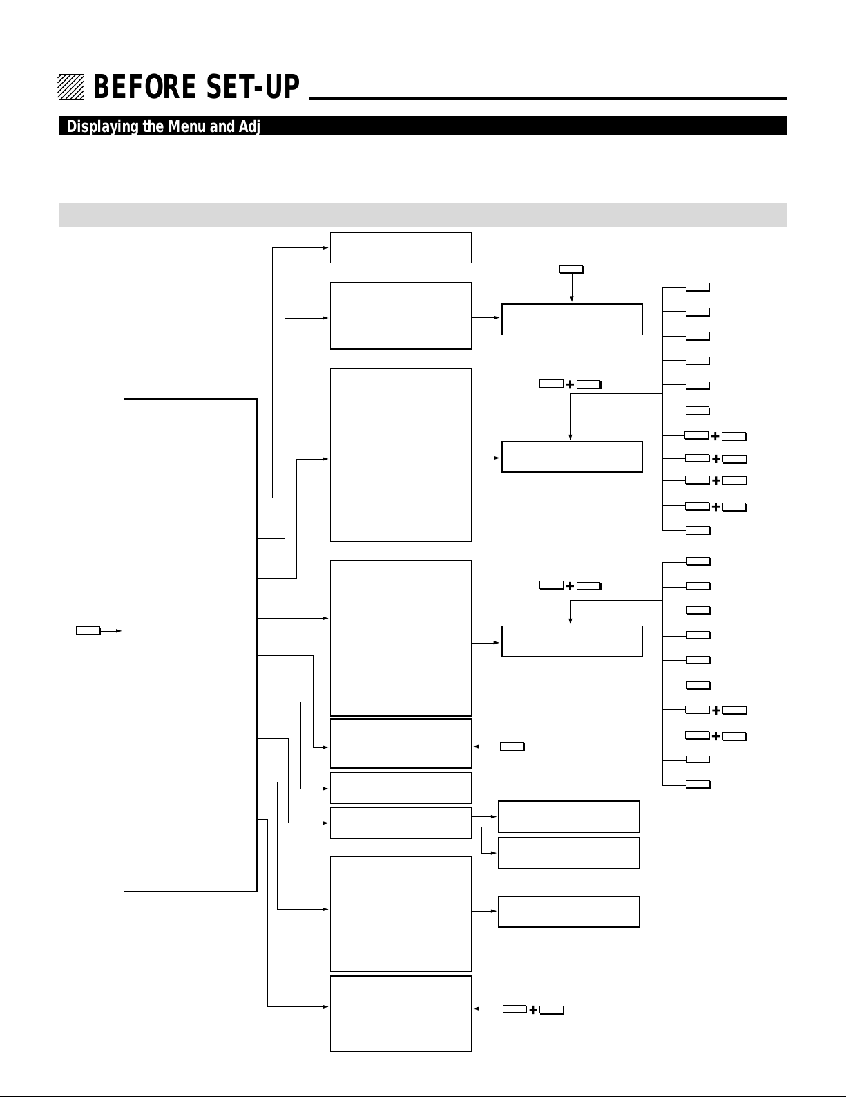
Displaying the Menu and Adjustment Screens
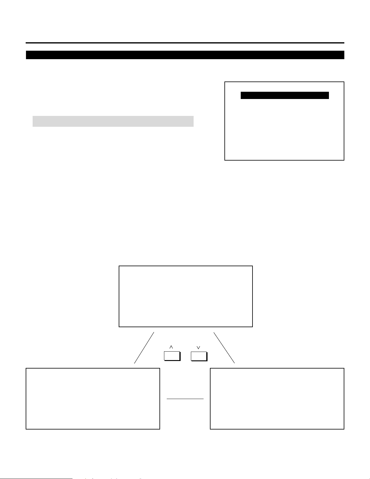
Access of all set-up functions is done through the menu system.
Depending upon button selection, your desired screen will be displayed as shown below:
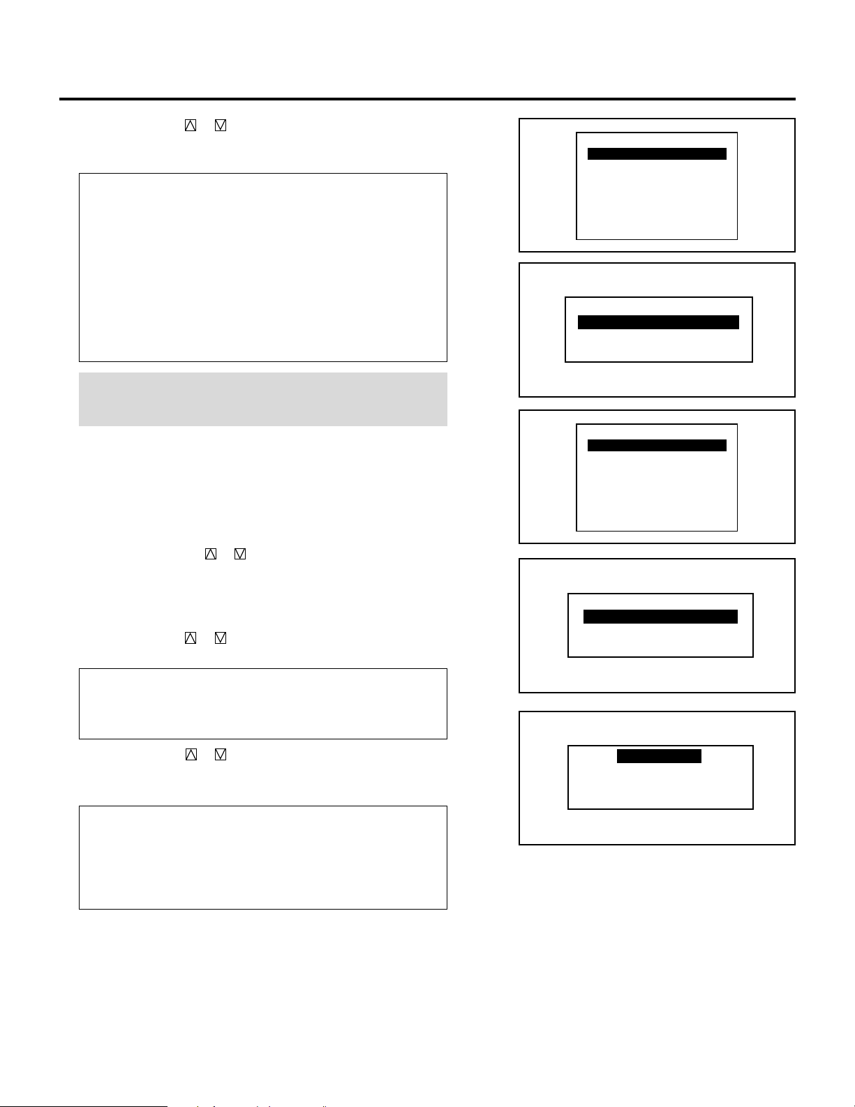
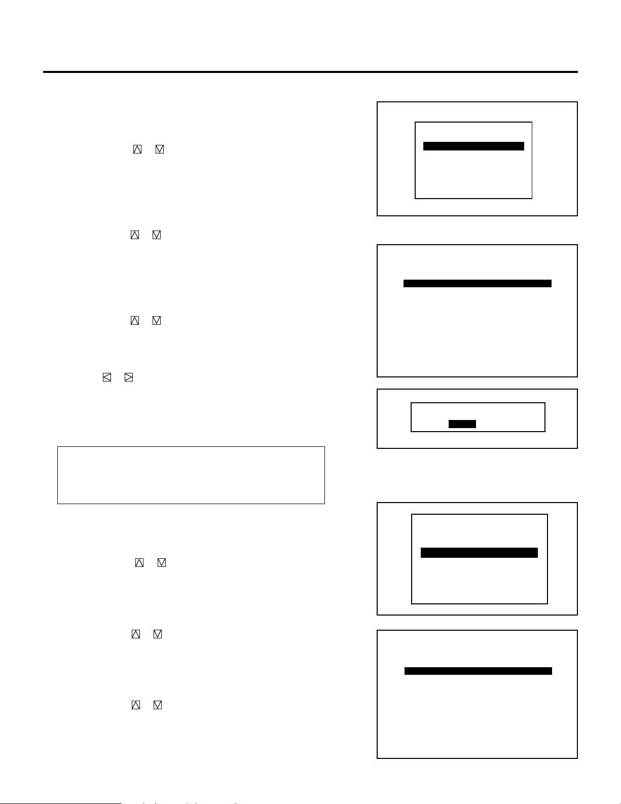
ADJUST menu
NOTE: Some function items will not be used depending on the input video signal or connected peripheral equipment.
ADJUST
ADJUST menu
– ADJUST –
1 / SIGNAL ENTRY
2 / FOCUS
3 / ALIGNMENT
4 / CONVERGENCE
5 / KELVIN
6 / R,G,B GAIN
7 / PASSCODE
8 / OPTION
SIGNAL ENTRY screen
FOCUS menu
– FOCUS –
1 / CENTER
2 / EDGE ALL
3 / EDGE SEPA.
4 / CORNER
ALIGNMENT menu
– ALIGNMENT –
01 / TILT, SKEW
02 / BOW
03 / AMPLITUDE
04 / LINEARITY
05 / KEY-STONE
06 / PIN-CUSHION
07 / LINEAR-BAL.
08 / KEY-BALANCE
09 / PIN-BALANCE
10 / LINE DIST.
11 / R,G,B POINT
CONVERGENCE menu
– CONVERGENCE –
1 / TILT, SKEW
2 / BOW
3 / AMPLITUDE
4 / LINEARITY
5 / KEY-STONE
6 / PIN-CUSHION
7 / LINEAR-BAL
8 / LINE DIST.
9 / POINT
10/ PHASE
– KELVIN –
1 / COLOR TEMP.
2 / WHITE BAL.
Adjustment screen
FOCUS
Adjustment screen
CTL
Sub menu and
Adjustment screen
CTL
R,B
Sub menu and
Adjustment screen
KELVIN
TILT
BOW
AMPLIT
LINEAR
G
KEYSTN
PINCUS
CTL
CTL
CTL
CTL
POINT
TILT
BOW
AMPLIT
LINEAR
KEYSTN
PINCUS
CTL
CTL
POINT
PHASE
LINEAR
KEYSTN
PINCUS
BOW
LINEAR
BOW
9 / REF. ADJUST
PASSCODE menu
OPTION menu
– OPTION –
NEW PASSCODE?
input screen
PASSCODE
DISABLE? menu
1 / SETTING MODE
2 / MENU MODE
3 / SEQUENCER
4 / PJ ADDRESS
Sub menu
/ Setting screen
5 / VERSION
6 / HOUR METER
7 / DEFAULT DATA
– REF. ADJUST –
1 / ASTIG
CTL
ADJUST
2 / BRIGHT UNIFORM.
3 / WHITE UNIFORM.
4 / RASTER CENTERING
14
Storing Projector Settings (Automatic Save Feature)
You have two options to store projector settings in the memory:
automatically and manually.
• Storing time is four seconds.
• The Automatic Save Feature mode has been set to DISABLE by
factory. For information on setting, see “Automatic Save Feature”
on page 86.
mWhen the Automatic Save Feature mode is set to “ENABLE”,
projector settings will be stored in the projector’s memory
automatically.
Settings are stored automatically when any one of the following
procedures is performed:
• The END button is pressed several times to return the adjustment screen to the source screen.
• One input is switched to another.
• The projector is turned off.
• After every 10 minutes of elapsed time.
BEFORE SET-UP
mWhen the Automatic Save Feature mode is set to “DISABLE”,
projector settings can be stored in the projector’s memory
manually.
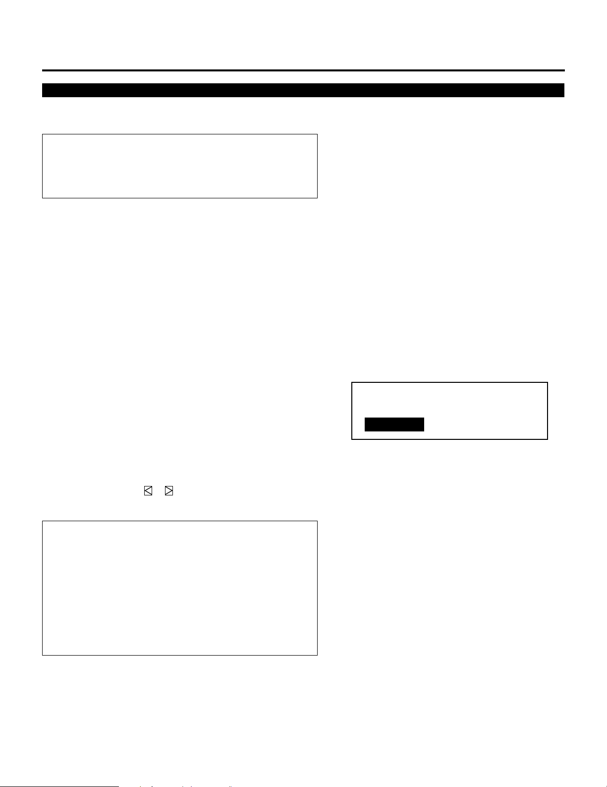
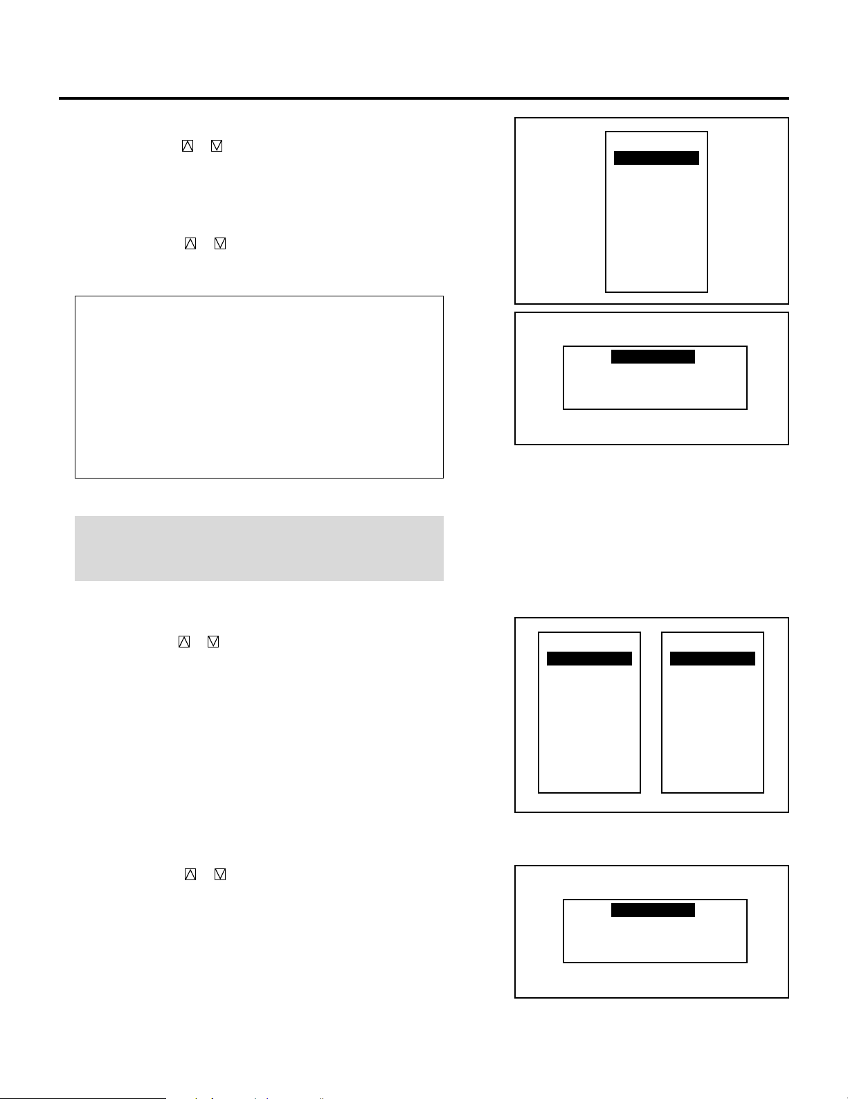
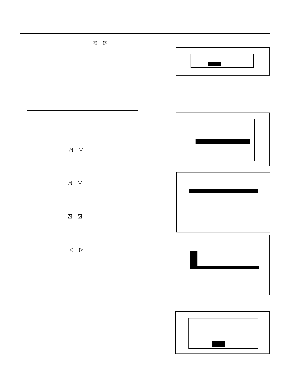
When you try to return the source screen by pressing END
several times, the “STORE ?” menu is displayed.
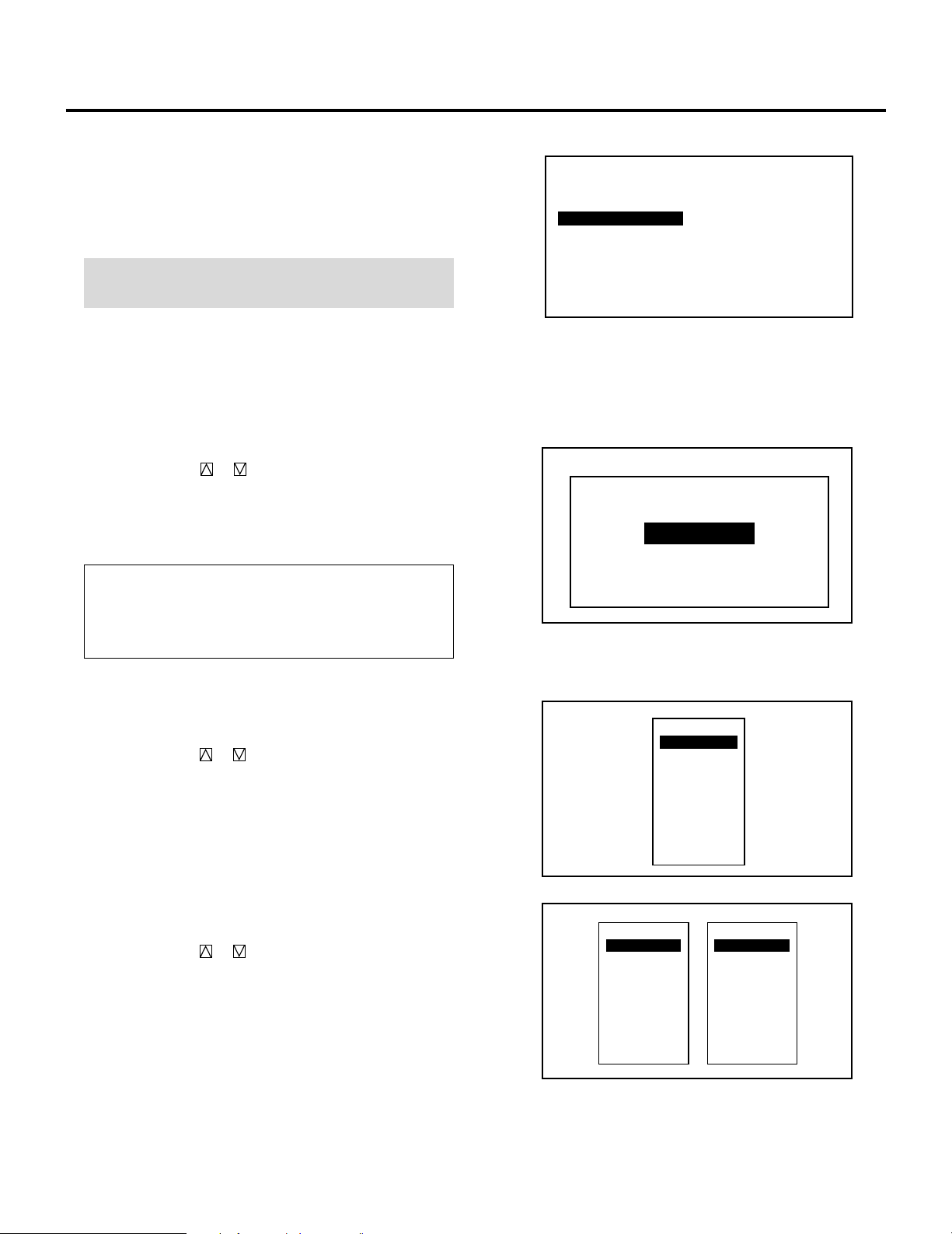
To manually save settings, proceed as follows:
1. Use the END button to display the “STORE” menu from the
current adjustment screen or menu.
2. Use the CURSOR or button to highlight “CURRENT”,
“NEW”, or “CANCEL” and press ENTER.
Items to select
• CURRENT ------Overwrites the currently projected signal and
saves the settings. NOTE: An unregistered signal
cannot be stored under the ''CURRENT''
settings.
• NEW ------------ Starting at memory location No.51, this function
saves an unregistered signal as a new signal in
memory.
• CANCEL -------- Does not save settings.
CURRENT
STORE ?
NEW CANCEL
15

BEFORE SET-UP
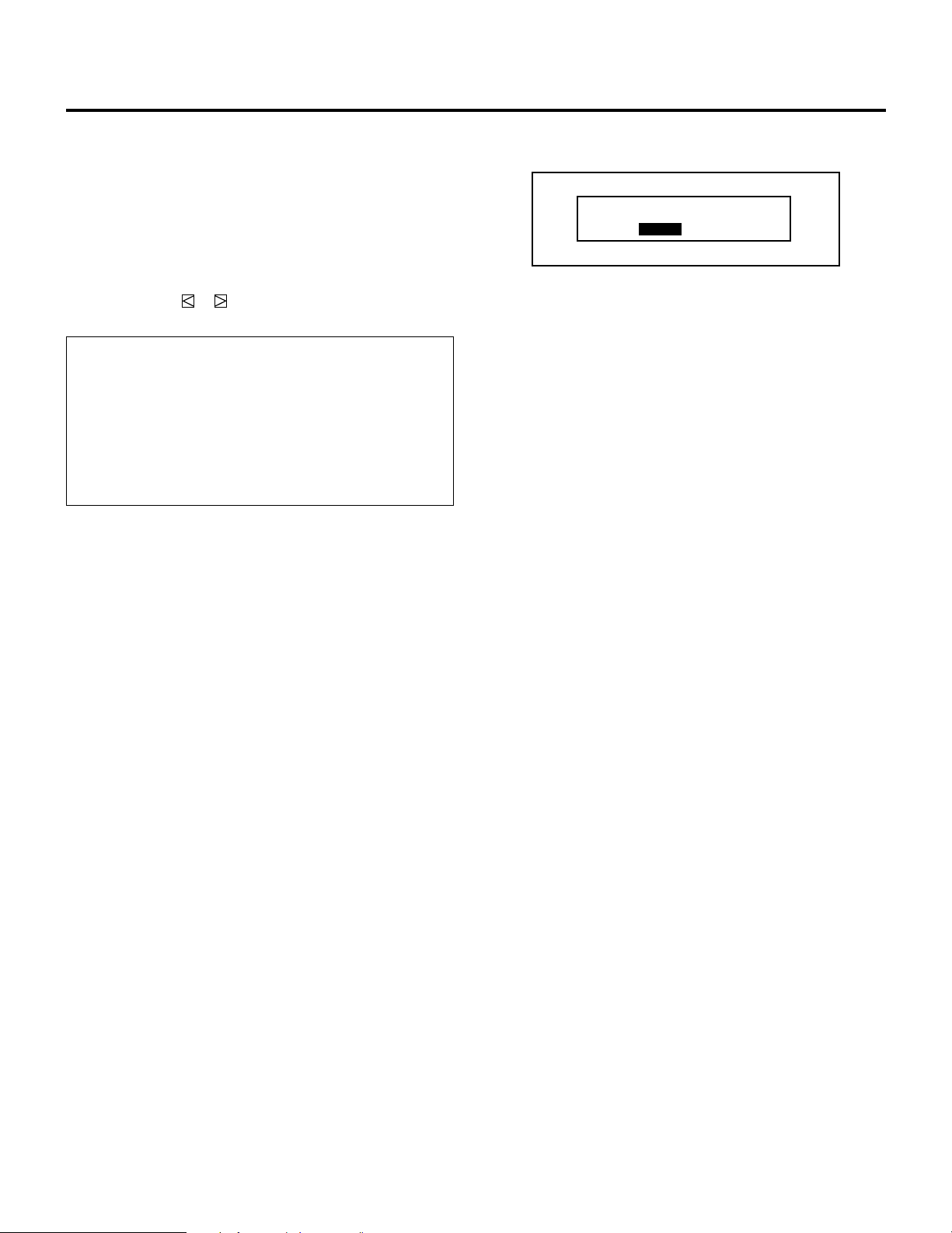
mWhen selecting “NEW”
The current settings are registered as a new signal and are
saved to an unassigned line starting at memory location
No.51.
A registered name is automatically given.
The “NEW ENTRY?” menu will be displayed.
Use the CURSOR or button to highlight “YES” or
“NO” and press ENTER.
Items to select
• YES------------- Registers settings as a new signal and
saves the signal in an unassigned
location starting at memory location
No.51.
• NO -------------- Does not register settings.
A registered name is given as follows:
VIDEO/S-VIDEO----- Video standard with a list number
e.g. NTSC51 or PAL52.
RGB --------------------- ”RGB” with a list number e.g.
RGB60.
COMPONENT -------- ”COMPO” with a list number, e.
g. COMPO 70.
NEW ENTRY?
LIST No. **
NAME ********
YES NO
NOTE:
• If the Input list does not have any unassigned memory
location starting at No. 51 then, the “NEW” item will be
selectable. For signal registration see “SIGNAL ENTRY”
on page 19.
• The Automatic Save Feature is available only for signals
listed in the INPUT LIST.
16

On ADJUST MODE
The ADJUST mode contains various adjustment items for set-up.
Open the ADJUST menu and select the item you wish to adjust. To
display the ADJUST menu, proceed as follows:
1 Press the ADJUST button.
• The projector may ask for your passcode.
2 Enter your registered passcode.
BEFORE SET-UP
When a passcode has not been registered:
• Since no passcode is programmed at the factory, pressing the
ADJUST button will open the ADJUST menu.
• See “Entering Passcode”, “Registering Passcode”, “Changing
Your Passcode” and “Canceling Your Passcode” on pages 61
through 66.
When your passcode has already been registered:
• When finishing the ADJUST mode, the “RETURN USER
MODE?” menu will be displayed. If you select “YES” and
press ENTER to end the ADJUST mode, you will have to
enter your passcode to re-enter the ADJUST mode.
• When finishing the ADJUST mode by either selecting “NO”
or pressing END, you do not need to enter your passcode to
re-enter the ADJUST mode. To exit the ADJUST mode
temporarily during adjusting, select “NO”.
PASSCODE?
****
17
BEFORE SET-UP
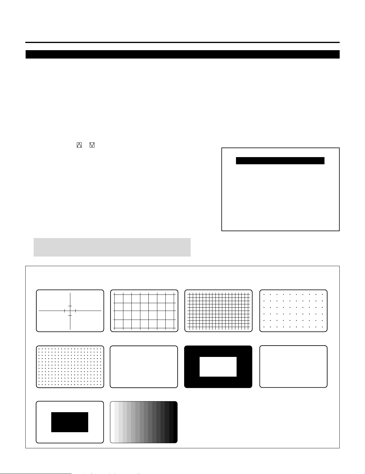
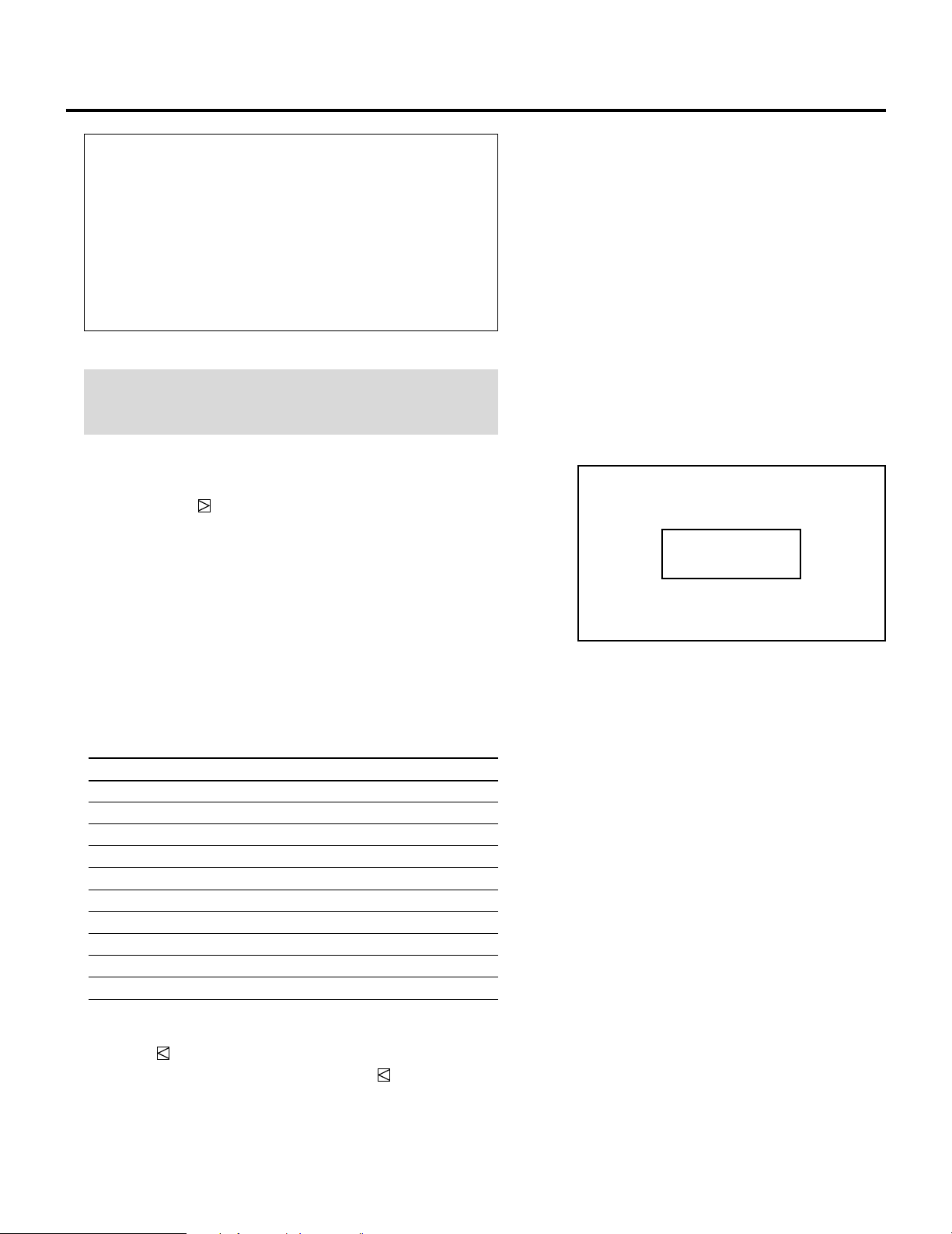
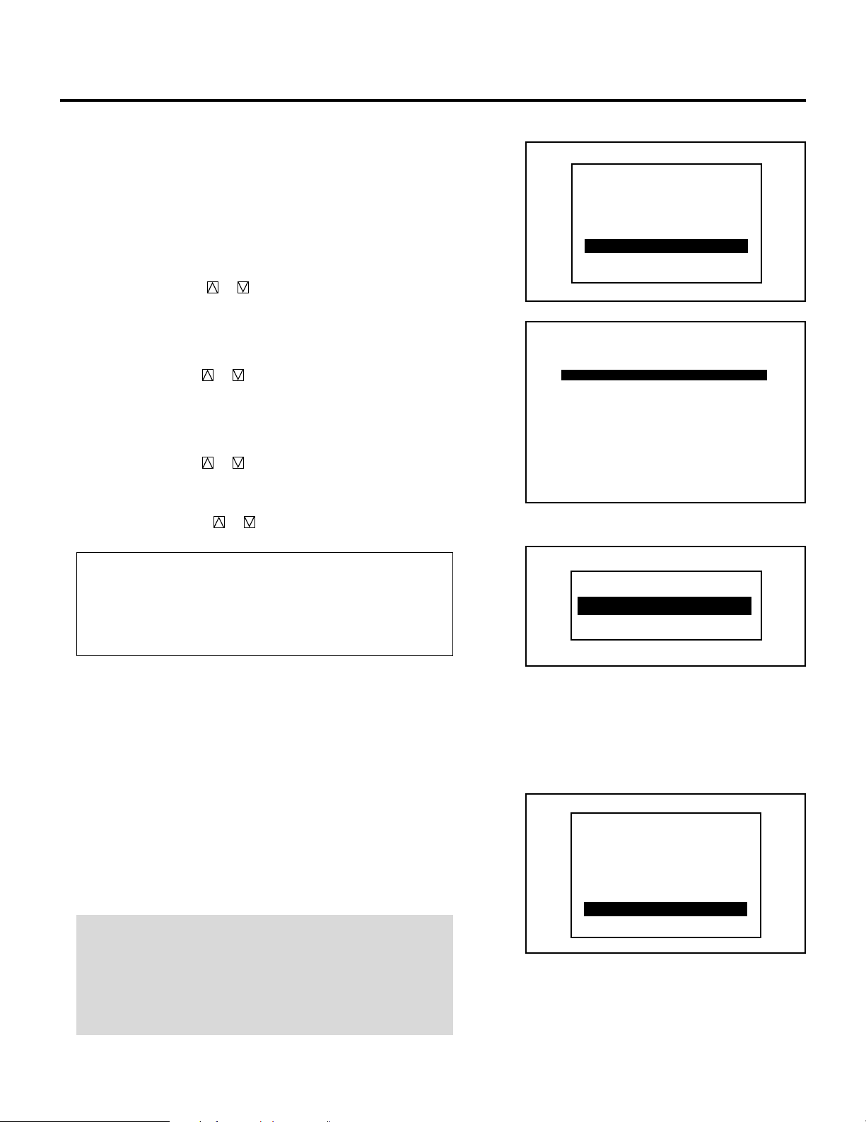
Test Pattern
This projector will generate a selection of test signals.
Ten kinds of internal test patterns can be selected from the TEST
PATTERN menu.
To display the TEST PATTERN menu, proceed as follows:
1 Press the TEST button on the Full function remote control.
• The “TEST PATTERN” menu will be displayed.
• When the END button is pressed, the “TEST PATTERN” menu
will disappear.
2 Use the CURSOR or button to highlight the test pattern you
wish to use and press ENTER.
• The selected test pattern will be displayed.
3 To return to the source screen, press the TEST and then the END
button.
• When the TEST button is pressed, the “TEST PATTERN”
menu will be displayed and when the END button is pressed,
the screen will be changed to the source screen.
• The projector will return to the original source screen by
pressing the END button only when no menu or no adjustment
screen is displayed.
– TEST PATTERN –
CROSS-HAIR
CROSS-COARSE
CROSS-FINE
DOT-COARSE
DOT-FINE
FOCUS
WINDOW-WHITE
ALL WHITE
WINDOW-BLACK
GRAY SCALE
NOTE: If there is no test pattern, the beams have been turned
off by the R, G, and B buttons on the remote control.
Adjustment test pattern
CROSS-HAIR CROSS-COARSE CROSS-FINE DOT-COARSE
DOT-FINE
WINDOW-BLACK
H H H H H H H H H H H H H H H H H H H H H H H H H H
H H H H H H H H H H H H H H H H H H H H H H H H H H
H H H H H H H H H H H H H H H H H H H H H H H H H H
H H H H H H H H H H H H H H H H H H H H H H H H H H
H H H H H H H H H H H H H H H H H H H H H H H H H H
H H H H H H H H H H H H H H H H H H H H H H H H H H
H H H H H H H H H H H H H H H H H H H H H H H H H H
H H H H H H H H H H H H H H H H H H H H H H H H H H
H H H H H H H H H H H H H H H H H H H H H H H H H H
H H H H H H H H H H H H H H H H H H H H H H H H H H
H H H H H H H H H H H H H H H H H H H H H H H H H H
H H H H H H H H H H H H H H H H H H H H H H H H H H
H H H H H H H H H H H H H H H H H H H H H H H H H H
H H H H H H H H H H H H H H H H H H H H H H H H H H
FOCUS WINDOW-WHITE
GRAY SCALE
ALL WHITE
18
12345
6
6
6
6
6
12345
12345
12345
12345
SIGNAL ENTRY.
On Signal Entry
The projector uses a micro-processor to automatically read and distinguish between all video signals input at the same time. These
signals are then used to make optimum adjustments for focus, convergence, alignment, etc. Various parameters must be registered
into the micro-processor beforehand to ensure the video signals are recognized and adjusted to optimum quality.
The Signal Entry registers these video signals in the SIGNAL ENTRY list and at the same time obtains the various parameters
pertaining to these signals. Always access this mode first whenever inputting video signals for the first time so that you can register
the video signals before making any adjustments. If the current input signal(s) has not been registered, the “UNREGISTERED
SIGNAL” message is displayed on screen.
NOTE: If you have software which changes scanning mode due to the graphic board of your PC (such as VGA), it will be necessary
to register signal entry for each scanning mode. This can be done using your PC by way of stopping the software in each scanning
mode and performing a signal entry operation.
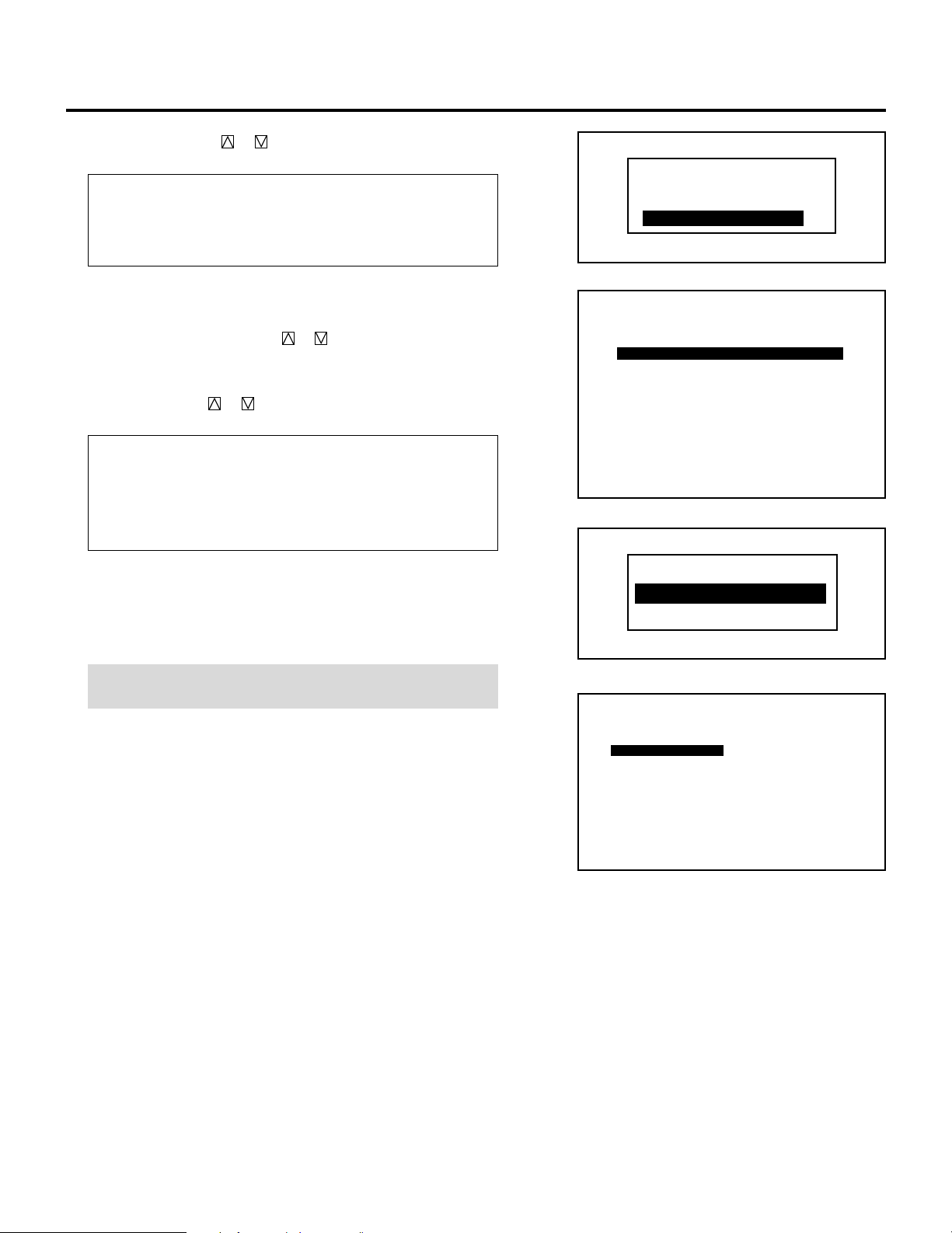
Signal Entry Procedures
To make the signal entry, proceed as follows:
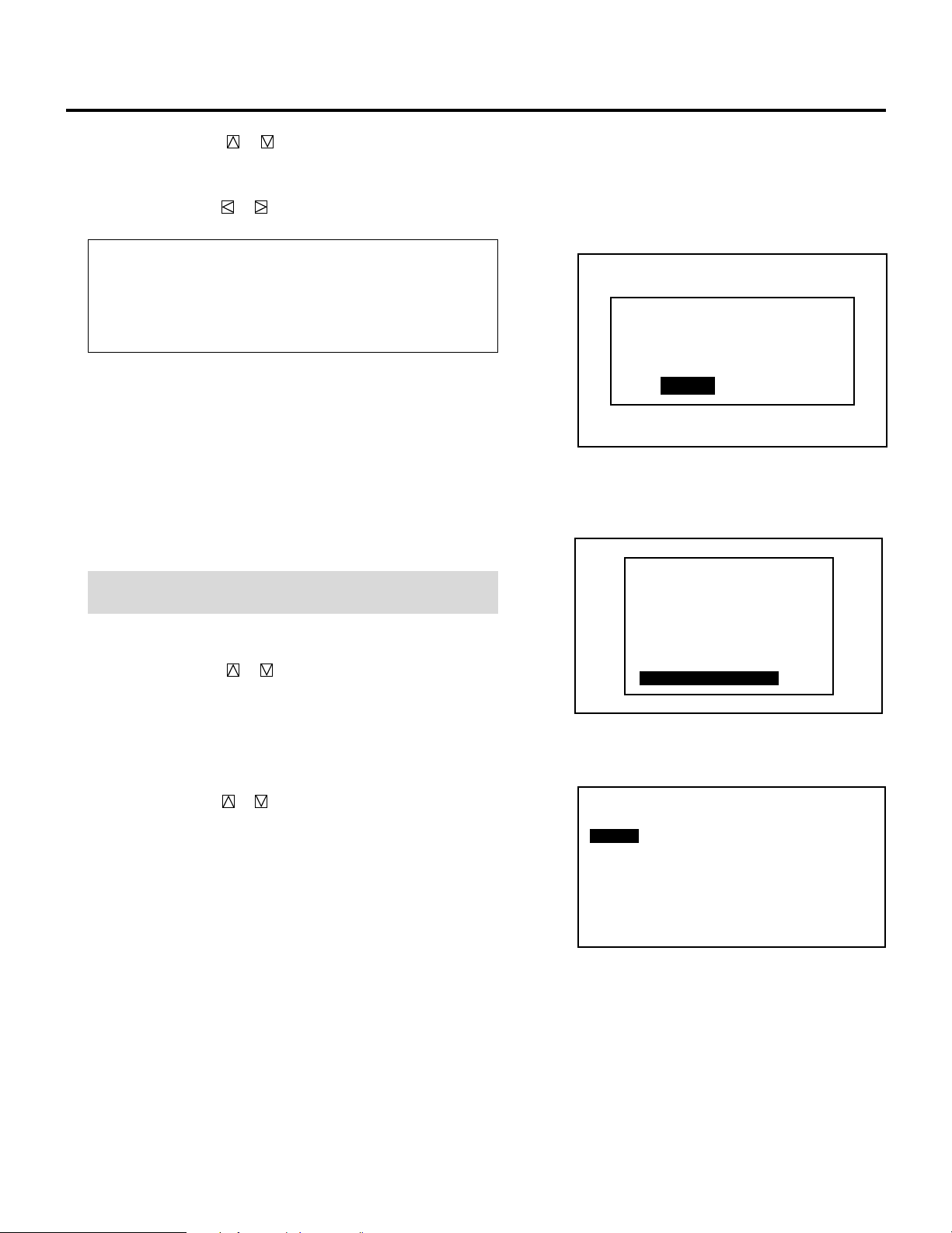
1 Press the ADJUST button.
• The “ADJUST” menu is displayed.
NOTE: The projector may ask you to enter your passcode. See
61 for the explanation of the PASSCODE.
2 Use the CURSOR or button to highlight the “1/SIGNAL
ENTRY” line and press ENTER.
• The “SIGNAL ENTRY” list will be displayed.
• You can also select the “SIGNAL ENTRY” list directly by
pressing the INPUT “1” button.
3 Use the CURSOR or button to select the desired line and
press ENTER.
• The Signal entry menu will be displayed.
– ADJUST –
1 / SIGNAL ENTRY
2 / FOCUS
3 / ALIGNMENT
4 / CONVERGENCE
5 / KELVIN
6 / R,G,B GAIN
7 / PASSCODE
8 / OPTION
9 / REF.ADJUST
NOTE: To advance to the next page or to the previous page,
hold down the CTL button then press the
CURSOR or button. To directly access a page, hold down
the CTL button then press any one of the INPUT buttons.
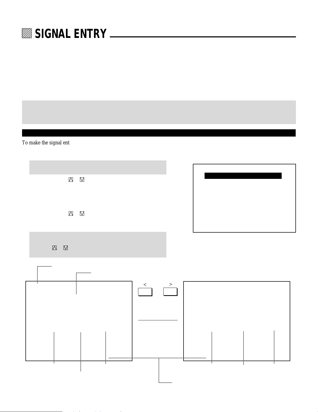
Page / total pages – sheet No.
Connect condition of the Switcher
P01/10–1 SIGNAL ENTRY
STANDALONE
NO
01
02
03
04
05
06
07
08
09
10
NAME
NTSC3.58
NTSC4.43
PAL
SECAM
VESA1024
OUTPUT DATA : LIST NO.✻✻
SOURCE
VIDEO
VIDEO
VIDEO
VIDEO
RGB
INPUT
A
A
A
A
A
§ ©
Signal name
Input terminal
P01/10–2 SIGNAL ENTRY
STANDALONE
NO
01
02
03
04
05
06
07
08
09
10
DATE
00/00/00
00/00/00
00/00/00
00/00/00
00/00/00
OUTPUT DATA : LIST NO.✻✻
Entry dateRgistered input module
FH
15.74kHz
15.74kHz
15.74kHz
15.74kHz
48.60kHz
Horizontal
Frequency
Output data for the signal currently projected.
FV
60.00Hz
60.00Hz
50.00Hz
50.00Hz
60.00Hz
Vertical
Frequency
19
SIGNAL ENTRY
4 Use the CURSOR or button to select the item and then press
ENTER.
• The Input terminal menu will be displayed.
Items to select
• NEW ENTRY ........ Registers a new signal.
• ENTRY COPY....... Copies any registered signal entry.
• ENTRY MOVE ...... Moves any registered signal entry.
• ENTRY DELETE ... Deletes any registered signal entry from
SIGNAL ENTRY.
• DATA COPY.........Copies gain data from any one of the
registered signals.
•
CHANGE DEFAULT
.Rewrites the data stored in DEFAULT AREA.
• SOURCE EDIT...... Changes setting various parameteres of the
registered signals.
NOTE: When a vacant line is selected, the “SIGNAL ENTRY”
menu has three items only: “NEW ENTRY”, “ENTRY COPY” and
“ENTRY MOVE”.
m Selecting “NEW ENTRY”
When connecting a signal for the first time, you need to register it
into the projector’s memory. You can copy the initial setting for
the new signal from any other signal that has already been
registered or use the factory preset setting.
To do this, proceed as follows:
1) Use the CURSOR or button to select “NEW ENTRY”
and press ENTER.
• The “INPUT TERMINAL SELECT”menu will be displayed.
When using the projector in stand alone application:
Use the CURSOR or button to select one of the three slots,
and press ENTER.
Items to select
• INPUT A.......... Standard
• INPUT B.......... Optional board
• INPUT C.......... Optional board
SIGNAL ENTRY
NEW ENTRY
ENTRY COPY
ENTRY MOVE
ENTRY DELETE
DATA COPY
CHANGE DEFAULT
SOURCE EDIT
SIGNAL ENTRY
NEW ENTRY
ENTRY COPY
ENTRY MOVE
SIGNAL ENTRY
NEW ENTRY
ENTRY COPY
ENTRY MOVE
ENTRY DELETE
DATA COPY
CHANGE DEFAULT
SOURCE EDIT
TERMINAL SELECT
INPUT A
INPUT B
INPUT C
Use the CURSOR or button to select “VIDEO”, “RGB”, “SVIDEO”, or “COMPO.”and press ENTER.
• The “NAME INPUT” screen will be displayed.
Items to select
•VIDEO......... Selecs the VIDEO input signal of this projector.
•RGB............ Selects the RGB input signal of this projector.
•S-VIDEO ..... Selects the S-VIDEO input signal of this projector.
•COMPO ...... Selects the Y/Cb/Cr input signal of this projector.
• Go on to Step 2).
20
VIDEO
RGB
S-VIDEO
COMP.
When using with a single Switcher ISS-6020/ISS-6020G:
Use the CURSOR or button to select the input slot number
of the Switcher and press ENTER.
• Input slot numbers are from 1 through 10.
Use the CURSOR or button to select “VIDEO”, “RGB”,
“S-VIDEO” or “COMPO.” and press ENTER.
• The “NAME INPUT” screen will be displayed.
Items to select
• VIDEO ---------Selects the signal from the VIDEO input
terminal of the VIDEO input board.
• RGB ----------- Selects the signal from the RGB input terminal
of the RGB input board.
• S-VIDEO ------Selects the signal from the S-VIDEO input
terminal of the VIDEO input board.
• COMPO. ------Selects the signal as COMPONENT signal from
the RGB input terminal of the RGB input board.
MASTER
SLOT–01
SLOT–02
SLOT–03
SLOT–04
SLOT–05
SLOT–06
SLOT–07
SLOT–08
SLOT–09
SLOT–10
VIDEO
RGB
S-VIDEO
COMP.
SIGNAL ENTRY
* Go on to Step 2).
NOTE: Signal registry is not possible unless the installed input
board matches the selected signal. Check if the installed input
board matches the slot number.
When using with two or more ISS-6020/ISS-6020G switchers:
Use the CURSOR or button to select the input slot number
of the master Switcher and press ENTER. Then select the slot
number of the slave Switcher and press ENTER.
• The “MASTER” menu will be displayed when the slot number
of the master Switcher is selected.
• The “SLAVE” menu will be displayed when the slot number of
the slave Switcher is selected.
• Input slot numbers are from 1 through 10.
• The “NAME INPUT” screen will be displayed when you finish
entering the slot number.
Use the CURSOR or button to select “VIDEO”, “RGB”,
“S-VIDEO” or “COMPO.” and press ENTER.
• The “NAME INPUT” screen will be displayed.
MASTER
SLOT–01
SLOT–02
SLOT–03
SLOT–04
SLOT–05
SLOT–06
SLOT–07
SLOT–08
SLOT–09
SLOT–10
VIDEO
RGB
S-VIDEO
COMP.
SLAVE
SLOT–01
SLOT–02
SLOT–03
SLOT–04
SLOT–05
SLOT–06
SLOT–07
SLOT–08
SLOT–09
SLOT–10
21
SIGNAL ENTRY
Items to select
• VIDEO ---------- Selects the signal from the VIDEO input
terminal of the VIDEO input board.
• RGB ------------ Selects the signal from the RGB input terminal
of the RGB input board.
• S-VIDEO ------- Selects the signal from the S-VIDEO input
terminal of the VIDEO input board.
• COMPO.--------Selects the signal as COMPONENT signal from
the RGB input terminal of the RGB input board.
• Go on to Step 2).
NOTE: Signal registry is not possible unless the installed input board
matches the selected signal. Check if the installed input board
matches the slot number.
2) Input the source name by selecting one character at a time with
the INPUT buttons 1 through 10 and by moving the cursor with
the CURSOR button. After finishing the selection of the
characters, press ENTER.
• Up to eight characters can be selected.
• Eight characters are assigned to one INPUT button.
• Whenever the INPUT button is pressed, characters will be rotated.
For example:
A → B → C → 1 → A .....
• When pressing the INPUT button while holding down the CTL
button, another group of characters will be rotated.
For example:
a → b → c → ! → a .....
• The characters corresponding to these INPUT buttons are as
follows:
NAME INPUT
––––––––
When using With CTL
INPUT 1 A, B, C, and 1 a, b, c, and !
INPUT 2 D, E, F, and 2 d, e, f, and “
INPUT 3 G, H, I, and 3 g, h, i, and #
INPUT 4 J, K, L, and 4 j, k, l, and $
INPUT 5 M, N, O, and 5 m, n, o, and %
INPUT 6 P, Q, R, and 6 p, q, r, and &
INPUT 7 S, T, U, and 7 s, t, u, and ‘
INPUT 8 V, W, X, and 8 v, w, x, and (
INPUT 9 Y, Z, ?, and 9 y, z, /, and )
INPUT 10 *, ,, ., and 0 ;, :, +, and -
• If you have made an error in the input of a character, use the
CURSOR button and enter the correct letter or number.
To delete one character, move the CURSOR button to the
character to be deleted and then press the NORMAL button.
To delete all the entered name, hold down the CTL button then
press NORMAL.
•The “INITIAL DATA SELECT” menu will be displayed.
22
3) Use the CURSOR or button to select an item and press
ENTER.
Items to select
• DEFAULT ............. Uses the data stored in the DEFAULT AREA
• TEMPORARY.......Uses the data which is currently displayed
•
ENTRY NUMBER
....Copies the data from the registered signal
SIGNAL ENTRY
INITIAL DATA SELECT
DEFAULT
TEMPORARY
ENTRY NUMBER
• When selecting “ENTRY NUMBER”, the “DATA COPY
SELECT SOURCE” message will be displayed at the bottom of
the screen. Use the CURSOR or button to select the signal
you wish to copy the initial settings from and press ENTER.
• The “DATA COPY MODE” menu will be displayed.
Use the CURSOR or button to select an item and press
ENTER.
Items to select
• ALL...................... Copies all the settings.
• EXCEPT H-POSI&PHASE
............................Copies the settings except H-position and
Phase adjustments data.
• The “SOURCE INFORMATION” screen will be displayed.
• Pressing END will return to the “SIGNAL ENTRY” list. Go on
to Step 5.
NOTE: You can check and change various parameters on the
“SOURCE INFORMATION” menu. See page 29.
P01/10-1
NO
0 1 NTSC3.58 VIDEO A
02
03
04
05
06
07
08
09
10
SIGNAL ENTRY
NAME
PAL
VGA480
NTSC
DATA COPY SELECT SOURCE
STANDALONE
SOURCE
VIDEO
RGB
S-VIDEO
DATA COPY MODE
ALL
EXCEPT H-POSI & PHASE
P01/03
SOURCE INFORMATION
INPUT
A
A
A
23
NAME
INPUT TERMINAL
INPUT SOURCE
VIDEO MODE
FREQUENCY
SYNC POLARITY
∗∗∗∗∗∗∗∗
INPUT A
RGB
RGB
FH = KHz
FV = Hz
HD(-) VD(+)
•
∗∗∗∗∗
•
∗∗∗∗∗
SIGNAL ENTRY
m When selecting “ENTRY COPY”
You can copy one of the registered input to another selected line.
To do this, proceed as follows:
1) Use the CURSOR or button to select “ENTRY COPY” and
then press ENTER.
•The “ENTRY COPY SELECT SOURCE” message will be
displayed at the bottom of the screen.
2) Use the CURSOR or button to select a line you wish to
copy from and then press ENTER.
• The “ENTRY COPY SELECT DESTINATION” message will
be displayed at the bottom of the screen.
3) Use the CURSOR or button to select a line you wish to
copy to and press ENTER.
• When there is already a registered signal in the selected line, the
“ENTRY DATA OVERWRITE?” prompt is displayed. Use the
CURSOR or button to select “YES” or “NO” and then
press ENTER.
• When the “ENTRY COPY END” message is displayed, this
completes the ENTRY COPY mode.
•
The “SIGNAL ENTRY” list is displayed. Go on to Step
5.
SIGNAL ENTRY
NEW ENTRY
ENTRY COPY
ENTRY MOVE
ENTRY DELETE
DATA COPY
CHANGE DEFAULT
SOURCE EDIT
P01/10-1
NO
0 1 NTSC3.58 VIDEO A
02
03
04
05
06
07
08
09
10
SIGNAL ENTRY
NAME
PAL
VGA480
NTSC
ENTRY COPY SELECT SOURCE
ENTRY DATA OVERWRITE?
YES NO
STANDALONE
SOURCE
VIDEO
RGB
S-VIDEO
INPUT
A
A
A
Items to select
• YES ......... Overwrites the selected signal that has already
been registered.
• NO ........... Stops overwriting.
m When selecting “ENTRY MOVE”
You can move one of the registered inputs to another selected
line. To do this, proceed as follows:
1) Use the CURSOR or button to select “ENTRY MOVE”
and then press ENTER.
• The “ENTRY MOVE SELECT SOURCE” message will be
displayed at the bottom of the screen.
2) Use the CURSOR or button to select a line you wish to
move and then press ENTER.
• The “ENTRY MOVE SELECT DESTINATION” message
will be displayed at the bottom of the screen.
3) Use the CURSOR or button to select a line you wish to
move to and press ENTER.
• When there is already a registered signal in the selected
line, the “ENTRY DATA OVERWRITE?” prompt will be
SIGNAL ENTRY
NEW ENTRY
ENTRY COPY
ENTRY MOVE
ENTRY DELETE
DATA COPY
CHANGE DEFAULT
SOURCE EDIT
P01/10-1
NO
0 1 NTSC3.58 VIDEO A
02
03
04
05
06
07
08
09
10
SIGNAL ENTRY
NAME
PAL
VGA480
NTSC
ENTRY MOVE SELECT SOURCE
STANDALONE
SOURCE
VIDEO
RGB
S-VIDEO
INPUT
A
A
A
24
displayed. Use the CURSOR or button to select
“YES” or “NO” and then press ENTER.
• When the “ENTRY MOVE END” message will be
displayed, this completes the ENTRY MOVE mode.
• The “SIGNAL ENTRY” list will be displayed. Go
on to Step 5.
Items to select
• YES ......... Overwrites the selected signal that has
already been registered.
• NO ........... Stops overwriting.
SIGNAL ENTRY
ENTRY DATA OVERWRITE?
YES NO
m When selecting “ENTRY DELETE”
You can delete one of the signals in the currently selected
lines. To do this, proceed as follows:
1) Use the CURSOR or button to select “ENTRY
DELETE” and then press ENTER.
• The “DELETE : SELECT START LINE” message
will be displayed at the bottom of the screen.
2) Use the CURSOR or button to select the first of
the lines you wish to delete and then press ENTER.
• The “DELETE : SELECT END LINE” message
will be displayed at the bottom of the screen.
3) Use the CURSOR or button to select the end of
the lines you wish to delete and then press ENTER.
• The “SELECT LINE DELETE?” menu will be
displayed.
4) Use the CURSOR or button to select "YES/NO"
and then press ENTER.
• The “SIGNAL ENTRY” list will be displayed. Go
on to Step 5.
Items to select
• YES ......... Deletes the selected signal that has already
been registered.
• NO ........... Stops deleting.
SIGNAL ENTRY
NEW ENTRY
ENTRY COPY
ENTRY MOVE
ENTRY DELETE
DATA COPY
CHANGE DEFAULT
SOURCE EDIT
P01/10-1
NO
0 1 NTSC3.58 VIDEO A
02
03
04
05
06
07
08
09
10
P01/10-1
NO
01 NTSC3.58 VIDEO A
02
03
04
05
06
07
08
09
10
SIGNAL ENTRY
NAME
PAL
VGA480
NTSC
DELETE : SELECT START LINE
SIGNAL ENTRY
NAME
PAL
VGA480
NTSC
PAL
DELETE : SELECT END LINE
STANDALONE
SOURCE
VIDEO
RGB
S-VIDEO
STANDALONE
SOURCE
VIDEO
RGB
S-VIDEO
S-VIDEO A
INPUT
A
A
A
INPUT
A
A
A
25
SELECTED LINES DELETE?
START LINE : 01
END LINE : 05
YES NO
SIGNAL ENTRY
m When selecting “DATA COPY”
To help assist in adjusting multiple inputs this projector has a
feature called DATA COPY. This feature allows you to copy the
memory data from one input to another input. By copying this
data from an input that has already been adjusted to an existing
input you will not have to do a complete adjustment.
To do this, proceed as follows:
1) Use the CURSOR or button to select “DATA COPY”
and then press ENTER.
• The “DATA COPY SELECT SOURCE” message will be
displayed at the bottom of the screen.
2) Use the CURSOR or button to select the signal to copy
from and then press ENTER.
• The “DATA COPY SELECT DESTINATION” message
will be displayed at the bottom of the screen.
3) Use the CURSOR or button to select the signal you wish
to copy to and press ENTER.
• The “DATA COPY MODE” menu will be displayed.
Use the CURSOR or button to select an item and press
ENTER.
Items to select
• ALL................................... Copies all the settings.
• EXCEPT H-POSI&PHASE.. Copies the settings except Hposition and Phase adjustments
data.
SIGNAL ENTRY
NEW ENTRY
ENTRY COPY
ENTRY MOVE
ENTRY DELETE
DATA COPY
CHANGE DEFAULT
SOURCE EDIT
P01/10-1
NO
0 1 NTSC3.58 VIDEO A
02
03
04
05
06
07
08
09
10
SIGNAL ENTRY
NAME
PAL
VGA480
NTSC
DATA COPY SELECT SOURCE
STANDALONE
SOURCE
VIDEO
RGB
S-VIDEO
DATA COPY MODE
ALL
EXCEPT H-POSI & PHASE
INPUT
A
A
A
• When “GAIN DATA COPY END” message will be displayed,
this completes the DATA COPY mode.
• The “SIGNAL ENTRY” list will be displayed. Go on to Step 5
m When selecting “CHANGE DEFAULT”
All of the adjustment data of the selected signal will be stored in
the DEFAULT AREA.
The data stored in the DEFAULT AREA can be recalled by
pressing the NORMAL button.
Selecting “DEFAULT” from the “INITIAL DATA SELECT”
menu during signal entry will utilize the data stored in the
“DEFAULT AREA”.
NOTE: The default area is comprised of six locations depending
on the horizontal frequency. The adjustment data will be stored in
one of these locations corresponding its horizontal frequency. To
refer the current default area, see "DEFAULT DATA" of the
OPTION menu on page 118.
To do this, proceed as follows:
26
SIGNAL ENTRY
NEW ENTRY
ENTRY COPY
ENTRY MOVE
ENTRY DELETE
DATA COPY
CHANGE DEFAULT
SOURCE EDIT
1) Use the CURSOR or button to select “CHANGE
DEFAULT” and press ENTER.
• The “STORE TO DEFAULT AREA?” will be displayed.
2) Use the CURSOR or button to select an item and press
ENTER.
Items to select
• YES ......... The picture parameter data of the selected signal
will be stored in the DEFAULT AREA.
• NO ........... The picture parameter data of the selected signal
will not be stored in the DEFAULT AREA.
SIGNAL ENTRY
STORE TO DEFAULT AREA?
( DEFAULT No. ✻ )
• If the “SIGNAL ENTRY” list will be displayed, this
completes the CHANGE DEFAULT mode.
• To end the “SIGNAL ENTRY” list, go on to Step 5.
m When selecting “SOURCE EDIT”
This feature allows you to change various parameters of the
source on the selected line. This can be done to the current
projected signal as well as not projected source.
NOTE: The setting INPUT TERMINAL cannot be done to the
current projected signal.
To do this, proceed as follows:
1) Use the CURSOR or button to select “SOURCE EDIT”
and then press ENTER.
• The “SOURCE INFORMATION” screen will be displayed.
• The “SOURCE INFORMATION” screen will be also
displayed by pressing the INFO button on the service remote
while the SIGNAL ENTRY is displayed.
2) Use the CURSOR or button to select the item and then
press ENTER.
• The selected setting screen is displayed.
YES NO
SIGNAL ENTRY
NEW ENTRY
ENTRY COPY
ENTRY MOVE
ENTRY DELETE
DATA COPY
CHANGE DEFAULT
SOURCE EDIT
P01/03 SOURCE INFORMATION
NAME ✻✻✻✻✻✻✻✻
INPUT TERMINAL INPUT A
INPUT SOURCE RGB
VIDEO MODE RGB
FREQUENCY FH=✻✻✻.✻✻kHz
FV=✻✻.✻✻Hz
SYNC POLARITY HD(–) VD(+)
27
SIGNAL ENTRY
SLOT–01
SLOT–02
SLOT–03
SLOT–04
SLOT–05
SLOT–06
SLOT–07
SLOT–08
SLOT–09
SLOT–10
MASTER
mWhen selecting "INPUT TERMINAL"
You can select the input terminal for the registered
signal. This feature is useful when you need to
change the input terminal due to adding optional equipment.
NOTE: This setting cannot be done to the current projected signal.
To do this, proceed as follows:
1) Use the CURSOR buttons to select “INPUT TERMINAL” and then press ENTER.
• The “INPUT TERMINAL SELECT” menu will be
displayed.
When used in the stand alone operation:
Use the CURSOR or button to select an input slot
from three slots: INPUT A, INPUT B, and INPUT C, and
press ENTER.
• The "SIGNAL ENTRY" screen is displayed.
Items to select
• INPUT A .............. Standard installed terminal
• INPUT B .............. Optional board terminal
• INPUT C .............. Optional board terminal
P01/03 SOURCE INFORMATION
NAME ✻✻✻✻✻✻✻✻
INPUT TERMINAL INPUT A
INPUT SOURCE RGB
VIDEO MODE RGB
FREQUENCY FH=✻✻✻.✻✻kHz
FV=✻✻.✻✻Hz
SYNC POLARITY HD(–) VD(+)
INPUT TERMINAL SELECT
INPUT A
INPUT B
INPUT C
When used with a single Switcher ISS-6020/ISS6020G:
Use the CURSOR or button to select the desired slot
number "1" through "10 (0)" of the Switcher and press
ENTER.
• The "SIGNAL ENTRY" screen is displayed.
When used with two or more Switchers ISS-6020/
ISS-6020G:
Use the CURSOR or button to select the master slot
number "1" through "10 (0)" first from the master menu,
then select the slave slot number "1" through "10 (0)"
from the slave menu and press ENTER.
• The "SIGNAL ENTRY" screen is displayed.
• For changing parameters of the setting feature, see pages
29 to 35.
28
MASTER
SLOT–01
SLOT–02
SLOT–03
SLOT–04
SLOT–05
SLOT–06
SLOT–07
SLOT–08
SLOT–09
SLOT–10
SLAVE
SLOT–01
SLOT–02
SLOT–03
SLOT–04
SLOT–05
SLOT–06
SLOT–07
SLOT–08
SLOT–09
SLOT–10
5 To complete the signal entry, press the END button.
• Whenever the END button is pressed, the menus will
sequence in this order:
“ADJUST” menu → Source screen.
• When your passcode is in effect, the “RETURN USER
MODE?” screen will be displayed. If this happens, use
the CURSOR or button to select either “YES” or
“NO” and press ENTER.
Items to select
• YES ......... When you try to enter the ADJUST mode
the next time, you will need to re-enter your
passcode.
• NO ........... When you try to enter the ADJUST mode
the next time, you will not need to re-enter
your passcode.
SIGNAL ENTRY
RETURN USER MODE?
YES NO
29
SIGNAL ENTRY
Checking and Setting Various Parameters
Parameters of the signal currently projected can be displayed.
For changing parameters of the other registered signals, perform on
the SIGNAL ENTRY screen. See pages 19 to 35.
To view or change the parameters, proceed as follows:
1 Press the ADJUST button.
The “ADJUST” menu will be displayed.
NOTE: The projector may ask you to enter your passcode.
• See page 59 for Passcode explanation.
2 Press the INFO button.
• The “SOURCE INFORMATION” screen will be displayed.
• The “SOURCE INFORMATION” screen will be displayed also
when you exit the “SIGNAL ENTRY” screen.
3 Check and / or set the various parameters of the signal currently
projected.
The menu items you can set are NAME, SYNC CONTROL,
COUNTER, DISPLAY TIME, SOURCE LOCK, AKB, G-Y
MATRIX, POSITION, FONT, APERTURE, SYNC TERMINATION and AFC. See the following pages for an explanation of
each setting.
– ADJUST –
1 / SIGNAL ENTRY
2 / FOCUS
3 / ALIGNMENT
4 / CONVERGENCE
5 / KELVIN
6 / R,G,B GAIN
7 / PASSCODE
8 / OPTION
9 / REF.ADJUST
P01/03 SOURCE INFORMATION
NAME ✻✻✻✻✻✻✻✻
INPUT TERMINAL INPUT A
INPUT SOURCE RGB
VIDEO MODE RGB
FREQUENCY FH=✻✻✻.✻✻kHz
SYNC POLARITY HD(–) VD(+)
P03/03 SOURCE INFORMATION
POSITION WIDE
FONT NORMAL
APERTURE
SYNC TERMINATION 75Ω
AFC NORMAL
MANUAL
LEVEL1
§ ©
§ ©
FV=✻✻.✻✻Hz
§ ©
P02/03 SOURCE INFORMATION
SYNC CONTROL AUTO
COMP.
COUNTER ✻✻✻✻✻
D I S P L A Y T I M E ✻✻✻✻: ✻✻
S O U R C E LOCK OFF
AKB OFF
G-Y MATRIX
30
 Loading...