

Page 1
NEC Solutions (America), Inc.
Visual Systems
VT46/460/465/560/660/660K Installation Guide
Desktop and Ceiling Mounted v2.0
Contents
Product Description, Lens Specs, Notes and Formulas Page 1
Diagrams and Distance Charts
Ceiling Mounted Installation
Desktop Setup
Cabinet Dimensions
Top, Front and Right Side
Bottom, Back and Left Side
Ceiling Mount Dimensions
Control Codes
Product Description
Type: 3 panel LCD projector Brightness: VT46: 1200 ANSI Lumens
VT46/460/465/560: 0.7” p-Si TFT VT460: 1500 ANSI Lumens
VT660/660K: 0.7” p-Si TFT wMLA VT465: 1800 ANSI Lumens
Resolution: VT46/460/465: 800x600 (SVGA) VT560: 1300 ANSI Lumens
VT560/660/660K: 1024 x 768 (XGA) VT660: 1700 ANSI Lumens
Dimensions: 12.2”(W) x 3.9”(H) x 9.6”(D) VT660K: 2000 ANSI Lumens
Weight: 6.5 lbs
Lens Specifications
Throw Ratio: 1.5 - 1.8:1(for 100” diagonal) Focal Length: 21.6mm – 25.9mm
Offset Angle: 9.5°-11.4°
Screen Sizes: 21”-300” Manual Zoom / Manual Focus
(for 100” diagonal) F/#: 1.7 – 2.0
Notes
For screen sizes not indicated on the projection charts, use the formulas below.
If a value in a chart does not match the results of the formulas, use the values in the chart.
The ceiling must be strong enough to support the projector and the installation must be in accordance with any local
building codes.
All formulas are based on a 4:3 aspect ratio and screen.
4:3 sources can be displayed on a 16:9 screen without vertical “squeezing”, see “Aspect Ratio” in the user manual.
Distances are in inches, for millimeters multiply by 25.4.
Distances may vary ±5%.
Formulas (for a 4:3 screen)
units: inches (for millimeters multiply final number by 25.4)
Calculate projection values by plugging the screen width (H) into the projection formulas.
Projection Formulas:
B = 0.3023H H = Horizontal Screen Width (4:3)
C (wide) = 1.5165H – 1.357 V = Vertical Screen Height (4:3)
C (tele) = 1.8197H – 1.629 B = Vertical distance between lens center and screen center
D = 0.0727H C = Throw distance
α (wide) = tan
α (tele) = tan
Screen Formulas (4:3):
H = V x 4/3
V = H x 3/4
Screen Diagonal = H x 5/4
-1
-1
www.necvisualsystems.com Page 1 of 7
Definitions:
(B/C(wide)) α = Throw Angle
(B/C(tele))
Page 2
Page 3
Page 4
Page 5
Page 6
Page 7
Page 2
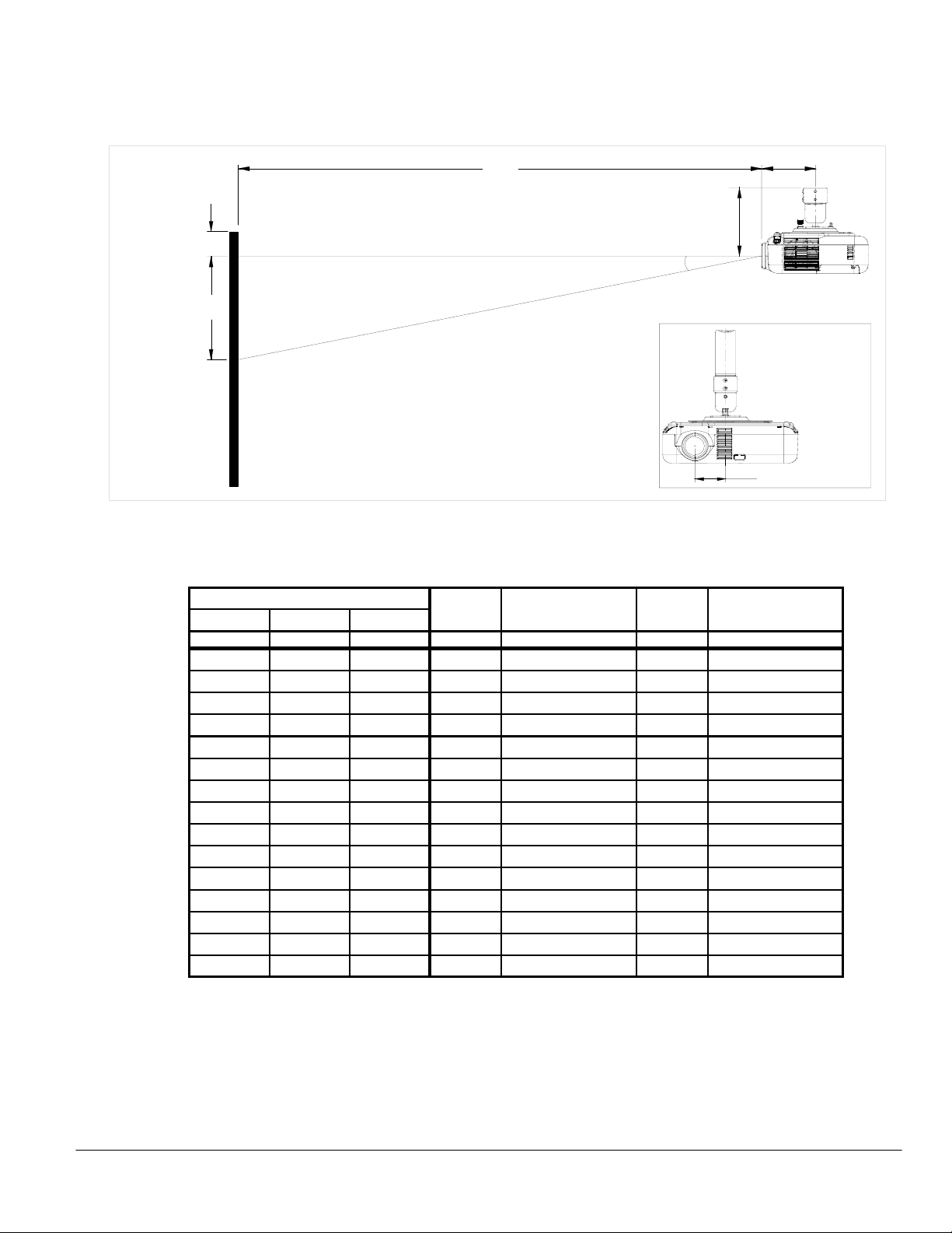
Ceiling Mounted Installation
The following diagram shows the relationship between projector position and the screen. Refer to the chart below for data.
Distances are in inches. For millimeters multiply by 25.4.
C
4.9"
Throw Distance
Screen Top
Lens Ctr
D
*6.5" w/pipe connector
*5.6" w/ceiling plate
α
B
Lens Offset from
Screen Ctr
Mount Pipe
2.8"
*See page 6 for mount details
Distance Chart (for popular screen sizes)
Note: For screen sizes not indicated on the chart, use the formulas on page 1.
Diagonal Width(H) Height(V) wide - tele wide - tele
www.necvisualsystems.com Page 2 of 7
Screen Size (4:3) C
inches inches inches inches inches
BD
inches
α
degrees
21 16.8 12.6 5.1 NA - 28.9 1.2 NA - 10.0
40 32 24 9.7 47.2 - 56.6 2.3 11.6 - 9.7
60 48 36 14.5 71.4 - 85.7 3.5 11.5 - 9.6
67 53.6 40.2 16.2 79.9 - 95.9 3.9 11.5 - 9.6
72 57.6 43.2 17.4 86.0 - 103.2 4.2 11.4 - 9.6
84 67.2 50.4 20.3 100.6 - 120.7 4.9 11.4 - 9.6
90 72 54 21.8 107.8 - 129.4 5.2 11.4 - 9.5
100 80 60 24.2 120.0 - 143.9 5.8 11.4 - 9.5
120 96 72 29.0 144.2 - 173.1 7.0 11.4 - 9.5
150 120 90 36.3 180.6 - 216.7 8.7 11.4 - 9.5
180 144 108 43.5 217.0 - 260.4 10.5 11.3 - 9.5
210 168 126 50.8 253.4 - 304.1 12.2 11.3 - 9.5
240 192 144 58.0 289.8 - 347.8 14.0 11.3 - 9.5
270 216 162 65.3 326.2 - 391.4 15.7 11.3 - 9.5
300 240 180 72.6 362.6 - 435.1 17.4 11.3 - 9.5
Page 3
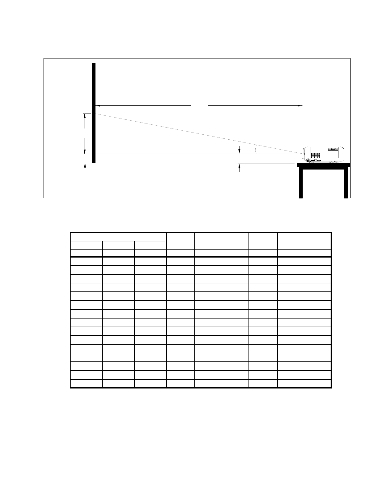
Desktop Setup
The following diagram shows the relationship between projector position and the screen. Refer to the chart below for data.
Distances are in inches. For millimeters multiply by 25.4.
C
Screen Ctr
B
Throw Distance
α
2.3"
Projector Feet
Lens Ctr
Scrn Bottom
D
Distance Chart (for popular screen sizes)
Note: For screen sizes not indicated on the chart, use the formulas on page 1.
Diagonal Width(H) Height(V) wide - tele wide - tele
Screen Size (4:3) C
inches inches inches inches inches
BD
inches
21 16.8 12.6 5.1 NA - 28.9 1.2 NA - 10.0
40 32 24 9.7 47.2 - 56.6 2.3 11.6 - 9.7
60 48 36 14.5 71.4 - 85.7 3.5 11.5 - 9.6
67 53.6 40.2 16.2 79.9 - 95.9 3.9 11.5 - 9.6
72 57.6 43.2 17.4 86.0 - 103.2 4.2 11.4 - 9.6
84 67.2 50.4 20.3 100.6 - 120.7 4.9 11.4 - 9.6
90 72 54 21.8 107.8 - 129.4 5.2 11.4 - 9.5
100 80 60 24.2 120.0 - 143.9 5.8 11.4 - 9.5
120 96 72 29.0 144.2 - 173.1 7.0 11.4 - 9.5
150 120 90 36.3 180.6 - 216.7 8.7 11.4 - 9.5
180 144 108 43.5 217.0 - 260.4 10.5 11.3 - 9.5
210 168 126 50.8 253.4 - 304.1 12.2 11.3 - 9.5
240 192 144 58.0 289.8 - 347.8 14.0 11.3 - 9.5
270 216 162 65.3 326.2 - 391.4 15.7 11.3 - 9.5
300 240 180 72.6 362.6 - 435.1 17.4 11.3 - 9.5
α
degrees
www.necvisualsystems.com Page 3 of 7
Page 4

Cabinet Dimensions
The following drawings show the cabinet dimensions.
Dimensions are in inches. For millimeters multiply by 25.4.
0
5
.
3
9
0
.
6
9
6
.
4
4
6
.
1
8
1
.
2
www.necvisualsystems.com Page 4 of 7
1.64 1.86
3
5
.
0
3
8
.
3
9
.
6
2
.
2
9
8
.
2
1
3
.
9
2
1
1
2
.
2
1
Page 5

Cabinet Dimensions (continued)
The following drawings show the cabinet dimensions.
Dimensions are in inches. For millimeters multiply by 25.4.
(VT460/465/560/660/660K)
4
5
.
1
7
7
.
1
2
1
.
5
1.6
9
4.9
2
M4*MAX8
For Mount
www.necvisualsystems.com Page 5 of 7
Rear View
Rear View
(VT46)
N
E
C
A
C
I
N
`
V
I
N
I
D
E
O
R
A
L
U
/
M
D
O
I
O
N
O
L
A
/
M
U
O
D
R
N
I
O
O
S
I
-
N
V
£
I
D
E
O
A
U
D
I
O
R
G
B
I
N
P
C
C
O
N
T
R
O
L
Page 6

Optional Ceiling Mount Dimensions (Model #: VT60CM)
The following drawings show ceiling mount dimensions.
Dimensions are in inches. For millimeters multiply by 25.4.
The VT60CM comes with a threaded pipe connector and a ceiling plate for flush mounting and minimal height.
Pipe Connector
8
2
.
4
.
7
6
5
.
5
1
8
Ceiling Plate
0
4
.
3
7
6
5
.
www.necvisualsystems.com Page 6 of 7
5
1
8
.
Page 7

Control Codes
Function Code Data
POWER ON 02H 00H 00H 00H 00H 02H
POWER OFF 02H 01H 00H 00H 00H 03H
INPUT SELECT RGB 02H 03H 00H 00H 02H 01H 01H 09H
INPUT SELECT VIDEO 02H 03H 00H 00H 02H 01H 06H 0EH
INPUT SELECT S-VIDEO 02H 03H 00H 00H 02H 01H 0BH 13H
PICTURE MUTE ON 02H 10H 00H 00H 00H 12H
PICTURE MUTE OFF 02H 11H 00H 00H 00H 13H
SOUND MUTE ON 02H 12H 00H 00H 00H 14H
SOUND MUTE OFF 02H 13H 00H 00H 00H 15H
Cable Connection
Communication Protocol:
Baud Rate: 19200 bps
Data Length: 8 bits
Parity: No Parity
Stop Bit: One bit
X on/off: None
Communications: Full duplex
PC Control Connector (DIN-8P)
To RxD of PC
678
345
12
To GND of PC
NOTE 1: Pins 2, 3, 5, 6 and 8 are used inside the projector.
NOTE 2: For long cable runs it is recommended to set communication speed within projector menus to 9600 bps.
To TxD of PC
www.necvisualsystems.com Page 7 of 7
 Loading...