

NEC VT70 Series, VT80 Series, VT60 Series, NP610 Series, NP-M350X Series Service Manual Supplement
...Page 1
MODEL VT60 Series NP600 Series
VT70 Series NP610 Series
VT80 Series NP-M350X Series
VT90 Series NP-M420X Series
NP3150 Series NP-M350XS Series
NP3250 Series NP-P420X Series
VT700 Series
VT770 Series
NP905 Series
LCD Projector
SERVICE MANUAL SUPPLEMENT
Better Service
Better Reputation
Better Profit
Optical alignment jig (optical axis alignment/polarizer alignment)
SAFETY CAUTION:
Before servicing this chassis, it is important that the service
technician read and follow the “Safety Precautions” and
“Product Safety Notice” in this Service Manual.
WARNING:
SHOCK HAZARD - Use an isolation transformer when servicing.
NEC DISPLAY SOLUTIONS, LTD.
Page 2
SAFETY PRECAUTIONS
2-1
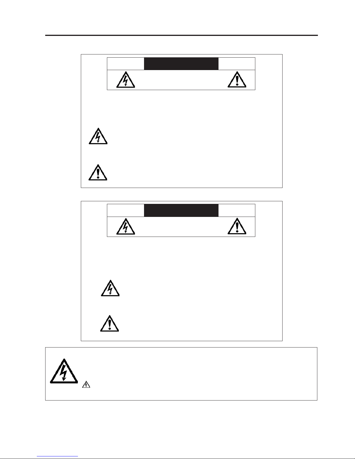
CAUTION
RISK OF ELECTRIC SHOCK
DO NOT OPEN
CAUTION: TO REDUCE THE RISK OF ELECTRIC SHOCK, DO NOT REMOVE
COVER. NO USER-SERVICEABLE PARTS INSIDE. REFER SERVICING
TO QUALIFIED SERVICE PERSONNEL.
This symbol warns the user that uninsulated voltage within th e u ni t
may have sufficient magnitude to cause electric shock. Therefore, it is
dangerous to make any kind of contact with any part inside of this unit.
This symbol aler ts th e u ser t hat i mportant literature conce rn in g t he
operation and maintenance of this unit has been included.
Therefore, it should be read carefully in order to avoid any problems.
ATTENTION
RISQUE D'ELECTROCUTION
NE PAS OUVRIR
MISE EN GARDE: A FI N DE REDUIRE LES RISQUES D' ELECTR OC UT IO N, NE
PAS DEPO SER LE C OUVE RCLE , IL N' Y A A UCU N E P I ECE
UTILISABLE A L'INTERIEUR DE CET APPAREIL. NE CONFIER
LES TRAVAUX D'ENTRETIEN QU'A UN PERSONNEL QUALIFIE.
Ce symbole a pour but de prévenir I' utilisateur de la présence d'
une tension dangereuse, non isolée se trouvant à l' intérieur de l'
appareil. Elle est d' une intensité sufsante pour constituer un risque
d' électrocution. Eviter le contact avec les pièces à l' intérieur de cet
appareil.
Ce symbole a pour but de prévenir l' utilisateur de la présence d'
importantes instructions concernant l' entretien et le fonctionnement de
cet appareil. Par conséquent, elles doivent être lues attentivement an
d' éviter des problèmes.
WARNING
HEATSINK MAY BE ENERGIZED.
TEST BEFORE TOUCHING.
Heat sink located on the power board, is electried.
mark is putted on the primary heat sink.
Pay attention to this area.
Page 3

2-2
SAFETY PRECAUTIONS
During servicing carefully observe the following.
1. OBSERVE ALL PRECAUTIONS
Items and locations that require special care during
serv-icing, such as the cabinet, chassis, and parts are
labelled with individual safety instructions. Carefully
comply with these instructions and all precautions in
the instruction manual.
2. BE CAREFUL OF ELECTRIC SHOCK
The chassis carries an AC voltage. If you touch the
chassis while it is still alive, you will get a severe
shock. If you think the chassis is alive, use an isolating
transformer o r gloves, or pul l out t he plug before
replacing any parts.
3. USE SPECIFIED PARTS
The components hav e be en chosen for min imu m
ammability and for specic levels of resistance value
and with s tand v oltag e. Re p lacem e nt pa r ts mu st
ma tch these orig ina l sp ecifica tio ns. Parts whose
specifications are particularly vital to safe use and
maintenance of the set are marked on the circuit
diagrams and parts list.
Substitution of these parts can be dangerous for you
and the customer, so use only specied parts.
4. REMOUNT ALL PARTS AND RECONNECT ALL
WIRES AS ORIGINALLY INSTALLED
For safety, insula t i n g tape and tub e s are u s e d
throughout, but some lift-off parts on the printed wiring
board require special attention.
All wires are positioned away from high-temperature
and high-voltage parts, and, if removed for servicing,
they m u s t be retu n e d precise l y to thei r o r iginal
positions.
5. LAMP
Be very careful of the lamp because it generates high
heat while it is used at high voltage. When replacing
the bulb, make sure it is cool enough.
6. LENS
Do not l ook i n to th e len s dur i ng pr oject i on. This
important to avoid damage to the eyes.
7. SERVICING
At the time of repair or inspection services, use an
earth band (wrist band), without fail.
8. RUN A COMPLETE SAFETY CHECK AT THE
COMPLETION OF SERVICING
Aft e r com p l e tion of serv i c i ng, co n firm th a t a l l
screws, parts, and wiring, removed or disconnected
for servicing, have b een returned to their o riginal
positions. Also examine if the serviced sections and
peripheral areas have suffered from any deterioration
as a result of servicing. In addition, check insulation
between external metallic parts and blades of walloutlet plugs. This examina tion is indispensable in
conrming complete establishment of safety.
(Insulation check)
Pull out a plug from a wall outlet to disconnect the
connection cable. Then turn on the POWER switch.
Use a 500V megger (Note 2) and confirm that the
insulation resistance is 1MΩ or more between each
terminal of the plug and exposed external metal (Note
1). If the measured value is below the specied level,
then it is necessary to inspect and x the set.
(Note 1)
Exposed external metal....RGB input terminals, control
terminals, etc.
(Note 2)
If a 500V megger is not available for an unavoidable
reason, then use a circuit tester or the like for inspection.
Page 4

Optical alignment jig (optical axis alignment/polarizer alignment)
This is our information for you indicating that we have provided for a jig kit (extension
connector plus extension connector PWB) to be used for optical alignments of the LCD
projector.
The jig kit to be provided (extension connector plus extension connector PWB) involves the
following 33 items.
<<Optical alignment jig (Extension connector/Connector PWB for extension)>>
No. Part No. Description Number of pins Photo Wire length
1 9N9CN001
CONNECTOR
(2P-900)
2P connector
900mm
2 9N9CN002
CONNECTOR
(3P-900)
3P connector
900mm
3 9N9CN003
CONNECTOR
(4P-900)
4P connector
900mm
4 9N9CN004
CONNECTOR
(5P-900)
5P connector
900mm
5 9N9CN005
CONNECTOR
(2P-300)
2P connector
300mm
6 9N9CN006
CONNECTOR
(3P-400)
3P connector
400mm
7 9N9CN007
CONNECTOR
(4P-300)
4P connector
300mm
8 9N9CN008
CONNECTOR
(5P-450)
5P connector
450mm
9 9N9CN009
CONNECTOR
(13P-600)
13P connector
600mm
10 9N9CN010
CONNECTOR
(15P-500)
15P connector
500mm
Page 5

No. Part No. Description Number of pins Photo Wire length
11 9N9CN011
CONNECTOR
(16P-500)
16P connector
500mm
12 9N9CN012
CONNECTOR
(18P-600)
18P connector
600mm
15 9N9FFC02
CABLE FFC
(24P-600)
24P connector
600mm
16 9N9FFC03
CABLE FFC
(30P-600)
30P connector
600mm
17 9N9FFC04
CABLE FFC
(32P-600)
32P connector
600mm
18 7N500019
CABLE FFC
(36P-600)
36P connector
600mm
19 9N9FFC06
CABLE FFC
(40P-600)
40P connector
600mm
13 9N9FFC07
CABLE FFC
(57P-600)
57P connector
600mm
20 9N9M0001
RELAY PWB
(2P)
2P PWB
21 9N9M0002
RELAY PWB
(3P)
3P PWB
22 9N9M0003
RELAY PWB
(4P)
4P PWB
23 9N9M0004
RELAY PWB
(5P)
5P PWB
24 9N9M0005
RELAY PWB
(15P)
15P PWB
Page 6

No. Part No. Description Number of pins Photo Wire length
25 9N9M0006
RELAY PWB
(13P)
13P PWB
26 9N9M0007
RELAY PWB
(24P)
24P PWB
27 9N9M0008
RELAY PWB
(30P)
30P PWB
28 9N9M0009
RELAY PWB
(32P)
32P PWB
29 9N9M0010
RELAY PWB
(36P)
36P PWB
30 9N9M0011
RELAY PWB
(40P)
40P PWB
31 9N9M0012
RELAY PWB
(18P)
18P PWB
32 9N9M0013
RELAY PWB
(57P)
57P PWB
33 9N9M0014
RELAY PWB
(16P)
16P PWB
Page 7

1. Kit and dummy load
The existing jig kit and dummy load are available only if these are kept in stock.
In the future, no jig kits and dummy loads will be put into inventory any more.
Reasons;
If any part of these items is not obtainable, no complete kit can be established any more.
Therefore, the maintenance of the inventory is impossible to continue.
The dummy load is expensive. In addition, it is extremely difficult to establish the former
model of a dummy load again.
If our supply system is maintained so that a single jig kit can be supplied, we can easily
accept an ordering for the supply of parts.
2. Method of optical axis alignments without a dummy load
In regard to the VT70, VT80, VT90, NP3150, NP3250, VT700, and NP905 Series, we have
made optical axis alignments by means of a dummy load. In the future, please make optical
axis alignments with the use of the extension connector and the extension connector PWB in
the same manner as for the polarizer alignments.
(The method of connection to make optical axis alignments with the use of the extension
connector and the extension connector PWB is the same as for the polarizer alignment. This
method is used for the NP600, NP610, and NP-M Series.)
In regard to the extension connector and the extension connector PWB needed to make
connections with the MAIN PWB, please refer to the relevant Service Manual (method of
adjustment, list of jigs) for each model.
Example (VT90 Series)
Connections to make the polarizer alignments
with the use of the extension connector and the
extension connector PWB
The connections indicated above can also be
used for optical axis alignment
Connections for optical axis alignments by
means of a dummy load
 Loading...